1
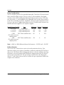
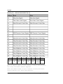
6244 LFA
User Manual
PN#4200-0211
Version 1.0
Table of Contents
6244 LFA ..................................................................................................... 5
EPIO 6244 LFA ....................................................................................... 7
Hardware................................................................................................ 7
Overview ........................................................................................... 7
Adjustable Voltages ...................................................................... 7
Digital Interface ............................................................................ 7
Configuration, Calibration, and Selftest......................................... 7
Power Considerations .................................................................. 8
Product Interface .......................................................................... 8
6244 LFA Functional Calls ....................................................................... 9
Lfa6244CalLogicLevel ...................................................................... 10
Lfa6244ChannelSetup ..................................................................... 11
Lfa6244Relay .................................................................................. 13
Lfa6244ResetLogicLevel .................................................................. 15
Lfa6244SerialRd .............................................................................. 16
Lfa6244SerialWrt ............................................................................ 17
Lfa6244SetLogicLevel ...................................................................... 18
Lfa6244SetLogicLevelGain .............................................................. 20
Lfa6244SetupConfig ........................................................................ 22
Lfa6244Status ................................................................................. 23
Board Specifications .............................................................................. 25
Address Maps .................................................................................. 26
Map 1 - Block 0 ......................................................................... 26
01 - Three-State Control Register Bit-Definitions ................... 26
02 - DAC Programming Register Bit-Definitions ..................... 26
04 - Power Supply Control Register Bit-Definition ................. 28
05 - Power Supply Monitor Bit-Definitions ............................ 28
06 - NML Detection Control Register Bit-Definitions ............. 29
07 - Power Supply Fault Detect Bit-Definitions ...................... 29
08 - DAC Load Strobe (VOH) ................................................ 30
09 - DAC Load Strobe (VOL) ................................................. 30
0A - DAC Programming Clock Enable/DAC Load Strobe (VIH) 30
0B - DAC Load Strobe (VIL)................................................... 30
40 - Relay Data Register Bit-Definitions ................................ 30
41 - Three-State Control Register Bit-Definitions ................... 30
Map2 - Block4 ........................................................................... 31
42 - Relay Disconnect Control Reg. Bit-Definitions ............... 31
46 - NML Detection Control Register Bit-Definitions ............. 31
48 - Relay Disconnect Latch (Bits 0-7) ................................... 31
49 - Relay Disconnect Latch (Bits 8-15) ................................. 31
4A - Relay Disconnect Latch (Bits 16-23)............................... 32
4B - Relay Disconnect Latch (Bits 24-31)............................... 33
4C - Relay Multiplexer Latch (Bits 0-7) .................................. 33
4D - Relay Multiplexer Latch (Bits 8-15) ................................ 33
4E - Relay Multiplexer Latch (Bits 16-23)............................... 33
4F - Relay Multiplexer Latch (Bits 24-31)............................... 34
Recommended Power-Up Sequence ..................................................... 35
.
6244 LFA
6244 LFA
EPIO 6244 Logic Family Adapter
5
6244 LFA
6
EPIO 6244 Logic Family Adapter
6244 LFA
EPIO 6244 LFA
Hardware
Overview
The EPIO 6244 Logic Family Adapter (LFA) board is designed to connect the
Extended Pattern Input/Output (EPIO) board to the device under test (DUT)
through the Digalog 2040 Series Tester’s Patchboard receiver. The LFA receives
data from the EPIO and converts it to programmable output voltage levels.
Differential drivers and receivers are used on the EPIO and the LFA to drive/
receive data through the Patchboard.
Adjustable Voltages
The adjustable logic levels between the LFA and the DUT can cover a 13 volt
differential range. The +/- rails are set by the user, but they cannot have more
than an 18 volt differential. There are four types of digital-to-analog converters
(DAC) on the LFA to program the four I/O logic levels: driver voltage output
high (VOH), driver voltage output low (VOL), receiver voltage input high (VIH)
minimum, and receiver voltage input low (VIL) maximum. Each group of eight
channels has its own set of user programmable I/O voltages. The receiver
thresholds can be programmed over a voltage range that is 2.5 volts less that
the upper rail and 2.5 volts more than the lower rails (13-volt differential).
Digital Interface
The LFA supports the bi-directional capabilities of the EPIO board. The last
four channels on each LFA (numbered 28-31) are used to control the three
states of the driver to the DUT, as well as the drivers that carry data back to
the EPIO. This option is user configurable per nibble on the LFA.
The LFA can detect no-man’s-land (NML) data from the DUT by checking the
outputs of the two receiver comparators (window). If the DUT pin voltage
level is above the lower threshold, but not above the upper threshold, the
driver that sends data back to the EPIO will be disabled. The EPIO board is
capable of detecting this condition and evaluating it accordingly.
Configuration, Calibration, and Selftest
The EPIO and LFA communicate by a serial link. It is used to enable/disable
the driver/receivers on the LFA, program the driver output voltages, program
the receiver threshold voltage, and read the ID of the LFA. It is also used to
perform functional selftest routines on the EPIO to LFA connection.
EPIO 6244 Logic Family Adapter
7
6244 LFA
Power Considerations
The LFA requires power to be provided externally. The 6244 LFA board needs
three external voltage sources. One is for the 5 volts needed for the digital
circuitry on the LFA, including the differential drivers and receivers. The other
two are for the +/- rails needed for the adjustable level circuitry that connects
to the DUT, including any DACs, amplifiers, references and comparators used.
It is up to the user to supply these power sources. Possible tester resources are
Patchboard fixed supplies or UUT power supplies.
Supply Power Per LFA
Use
Minimum Typical Maximum
Vcc (0.9A)
Digital Logic
4.75V
5V
5.25V
+9 (0.05A)
DACs and Reference
+8V
+9V
+10V
-9 (0.05A)
DACs and Reference
-8V
-9V
-10V
+Rail
DUT Driver and Receiver
8V
9
10V
(*Provide necessary
output power)
-Rail
DUT Driver and Receiver -8V
-9
0V
(*Provide necessary
output power)
Note: (+Rail) to (-Rail) differential must be between +12VDC and +18 VDC.
Product Interface
The LFA to DUT connections consist of several protection devices. First,
disconnect relays are in place to break the connection with the DUT before or
after a test. This allows other testing to be done to each pin without removing
the fixture. Second, posistors and SCR/Diode clamps protect the LFA driver’s
and receivers from the DUT. The pin voltage is held to the rail voltage plus
about 0.7 volts. Both of these devices increase the pin capacitance and/or the
output series resistance.
8
EPIO 6244 Logic Family Adapter
6244 LFA
6244 LFA Functional Calls
The functional calls associated with the EPIO’s 6244 Level Logic Family
Adapter (6244 LFA) card gives the user the ability to configure the 6244 LFA.
The configuration capabilities include setting the Driver output logic levels and
the Receiver threshold logic levels, setting the channel direction, retrieving
the LFA’s status, and controlling the disconnect relays. In addition to the
functional calls that configure the 6244 LFA are the serial read and write
calls. These calls allow the EPIO to communicate to the 6244 LFA through the
serial interface on the Patchboard. The configuration functional calls use the
serial calls to configure the 6244 LFA but the serial communication calls can
also be used to configure user added capabilities to an LFA.
EPIO 6244 Logic Family Adapter
9
6244 LFA
Lfa6244CalLogicLevel
This functional call is used when calibrating one of the eight driver output
levels or one of the eight receiver threshold levels on a 6244 LFA. This routine
is separate from Lfa6244SetLogicLevel because it will accept a bit count
instead of a voltage. By using this call, the DAC can be set to a bit count and
the output voltage measured. Therefore, the input bit counts and the
measured voltages can be used to determine the DACs gain in Bits/Volt and
the offset in Bits.
Visual Basic Declaration:
lfa6244.bas
Public Sub Lfa6244CalLogicLevel (ByVal BdNum As Integer, ByVal ByteNum As
Integer, ByVal VoltLevSel As Integer, ByVal DacBits As Integer)
CVI Declaration:
dli6244.h
u_int32 DLI6244_LFA6244CalLogicLevel (int16 bdNum, int16 byteNum, int16
voltLevSel, int16 DACBits);
Call Lfa6244CalLogicLevel(BdNum, ByteNum, VoltLevSel,
DacBits)
WHERE:
BdNum
=
0
The EPIO board associated with the RFALLFA that is going to
accessed.
to 7.
0
The byte number of the DAC whose gain and offset is going to be
stored.
to 3.
0
1
2
3
Selects which voltage reference is going to be set to the given bit
count.
Voltage Out High (VOH).
Voltage Out Low (VOL).
Voltage In High (VIH).
Voltage In Low (VIL).
0
The bit count the given reference DAC is going to be set to.
to 4095.
ByteNum
=
VoltLevSel
=
=
=
=
DacBits
=
10
EPIO 6244 Logic Family Adapter
6244 LFA
Lfa6244ChannelSetup
This functional call is used to configure 6244 LFA channels as fixed drivers,
fixed receivers, or bi-directional. Two separate eight-bit values are used to
control the 32 channels on each board. One value is used for the driver
channels and the other is used for the receiver channels. High logic values in
the bits of the DriverEnable byte fix those channels as full- time drivers. High
logic values in the bits of the ReceiverEnable byte fix those channels as fulltime receivers. Channels that are specified as both drivers and receivers will be
configured as bi-directional.
The last four-channel group on the 6244 LFA may only be configured as fixed
drivers or fixed receivers. If any channels on an LFA are bi-directional, then
this last nibble on the LFA (channels 28-31) must be configured as fixed
drivers, or errors will result. The last four channels on each LFA control the
I/O direction of eight channels that are configured as bi-directional (although,
channel 31 only controls the direction of four channels). A high logic bit on
any control channel will cause the corresponding group of bi-directional
channels to drive out to the LFA. A logic low will disable the drivers, allowing
data to be received from the LFA. This ability follows the R0 Driver format,
regardless of what format may be selected elsewhere.
Unspecified channels will be configured as receivers. It is recommended that
these channels should be masked out by clearing that bit in the Mask memory.
Visual Basic Declaration:
lfa6244.bas
Public Sub Lfa6244ChannelSetup (ByVal BdNum As Integer, ByVal DriverEnable As
Byte, ByVal ReceiverEnable As Byte)
CVI Declaration:
dli6244.h
u_int32 DLI6244_LFA6244ChannelSetup (int16 bdNum, u_char driverEnable, u_char
receiverEnable);
Call Lfa6244ChannelSetup(BdNum, DriverEnable,
ReceiverEnable)
WHERE:
BdNum
=
0
The number of the EPIO board connected to the LFA to be set.
to 7.
EPIO 6244 Logic Family Adapter
11
6244 LFA
DriverEnable
=
=
=
=
=
=
=
=
0
1
2
3
4
5
6
7
ReceiverEnable
=
=
=
=
=
=
=
=
0
1
2
3
4
5
6
7
A logic one specifies which channels are to be enabled as drivers to
the DUT.
Channels 0-3
Channels 4-7
Channels 8-11
Channels 12-15
Channels 16-19
Channels 20-23
Channels 24-27
Channels 28-31
A logic one specifies which channels are to be enabled as receivers
from the DUT.
Channels 0-3
Channels 4-7
Channels 8-11
Channels 12-15
Channels 16-19
Channels 20-23
Channels 24-27
Channels 28-31
NOTE: If a bit is high in both ‘DriverEnable’ and ‘ReceiverEnable’, the corresponding
group of four channels will be configured as Bi-Directional.
12
EPIO 6244 Logic Family Adapter
6244 LFA
Lfa6244Relay
This functional call is used to either connect one DUT pin to the LFA, the Mux
output to the fixture motherboard, or connect an LFA output to the Mux pin
for calibration. It is also used to completely disconnect the DUT pin from both
the LFA and the Mux.
In addition, if ‘ChanNum = -1’, this function can be used to disconnect all 32
of the DUT pins associated with this LFA from either the LFA, the Mux, or from
both based on the value of ‘State’.
When the LFA is first powered up, the DUT pins are disconnected from both
the LFA and the Mux. Therefore, the command to connect a DUT pin to
either one must be given every time the LFA is powered up. By doing this the
LFA does not need to be powered down every time the DUT is changed.
However, the power to the DUT must then be controlled by relays or be
separate supplies than those used by the LFA.
Multiple DUT pins can be connected to the LFA at once. This would be the
normal operation when testing a DUT with an EPIO/DPIO. The normal
operation for using the Mux input to the fixture’s motherboard would be to
only connect one DUT pin to the Mux input at a time. However, the hardware
and software allow for more than one DUT pin to be connected to the Mux at
a time. This is allowed for selftest purposes (two or more DUT pins can be
connected to each other on the bus input to the Mux). Therefore, if only one
DUT pin is to be connected to the Mux input at a time, the user has to
disconnect the previous DUT pin every time a different one is connected to
the Mux. It should be noted that connecting a DUT pin to the LFA or to the
Mux input is mutually exclusive, unless the ‘State’ parameter is configured for
the calibration mode. The software prevents a DUT pin from being connected
to both the LFA and the Mux input at the same time unless in calibration
mode.
NOTE: There is a maximum value for the turn on time of the relays. The time
needed to turn on a relay was not included in this function because
the total time to turn on more than 100 relays would be excessive.
Therefore, it was determined that the delay time should be up to the
user and it should be done after all of the channels have been
configured. One relay needs 6 milliseconds to turn on.
EPIO 6244 Logic Family Adapter
13
6244 LFA
Visual Basic Declaration:
lfa6244.bas
Public Sub Lfa6244Relay (ByVal BdNum As Integer, ByVal ChanNum As Integer, ByVal
State As Integer)
CVI Declaration:
dli6244.h
u_int32 DLI6244_LFA6244Relay (int16 bdNum, int16 chanNum, int16 state);
Call Lfa6244Relay(BdNum, ChanNum, State)
WHERE:
BdNum
=
0
ChanNum
The number of the EPIO board connected to the LFA to be set.
to 7.
If this number is 0 - 31, this parameter specifies which DUT pin is to
be configured. The number given designates the LFA channel which
is connected to the pin on the DUT. If ChanNum is minus one (-1),
all 32 of the DUT pins will be disconnected from either:
The LFA and the Mux if State = 0
The LFA if State = 1
The Mux input if State = 2
The LFA and the Mux if state = 3.
State
=
=
=
=
=
=
=
=
14
0
1
2
3
If the ChanNum parameter is 0 - 31, the State parameter specifies
whether or not a single DUT pin should be connected to the LFA,
the Mux, or disconnected from both.
Disconnect the DUT pin from the LFA and the Mux.
Connect the DUT pin to the LFA.
Connect the DUT pin to the Mux.
Configure for calibration, close both relays.
0
1
2
3
If the ChanNum parameter is -1, the State parameter specifies
whether all 32 of the DUT pins should be disconnected from
the LFA, the Mux, or both.
Disconnect all 32 DUT pins from the LFA and the Mux.
Disconnect all 32 DUT pins from the LFA.
Disconnect all 32 DUT pins from the Mux.
Disconnect all 32 DUT pins from the LFA and the Mux.
EPIO 6244 Logic Family Adapter
6244 LFA
Lfa6244ResetLogicLevel
This functional call is used to reset all 16 DACs to 0 volts on the LFA
connected to the EPIO board designated by the BdNum parameter. The 16
DACs include the four VOH DACs, four VOL DACs, four VIH DACs, and four
VIL DACs.
Visual Basic Declaration:
lfa6244.bas
Public Sub Lfa6244ResetLogicLevel(ByVal BdNum As Integer)
CVI Declaration:
dli6244.h
u_int32 DLI6244_LFA6244ResetLogicLevel (int16 bdNum);
Call Lfa6244ResetLogicLevel(BdNum)
WHERE:
BdNum
=
0
The number of the EPIO board connected to the LFA to be reset.
to 7.
EPIO 6244 Logic Family Adapter
15
6244 LFA
Lfa6244SerialRd
This functional call serially reads an eight bit value from the LFA board
associated with the EPIO board given by ‘BdNum’ from the LFA’s offset given
by ‘Offset’. The eight bit value is returned in ‘SerRetByte’.
Visual Basic Declaration:
lfa6244.bas
Public Sub Lfa6244SerialRd (ByRef SerRetByte As Byte, ByVal BdNum As Integer,
ByVal Offset As Integer)
CVI Declaration:
dli6244.h
u_int32 DLI6244_LFA6244SerialRd (char *serRetByte, int16 bdNum, int16 offset);
Call Lfa6244SerialRd(SerRetByte, BdNum, Offset)
WHERE:
SerRetByte
The byte of data read from the LFA.
BdNum
The number of the EPIO board connected to the LFA to be
accessed.
to 7.
=
Offset
16
0
The register offset on the LFA board.
EPIO 6244 Logic Family Adapter
6244 LFA
Lfa6244SerialWrt
This functional call serially writes an eight bit value to the LFA board
associated with the EPIO board given by ‘BdNum’ to the LFA’s offset given by
‘Offset’. The eight bit value written is in ‘SerByte’.
Visual Basic Declaration:
lfa6244.bas
Public Sub Lfa6244SerialWrt(ByVal BdNum As Integer, ByVal Offset As Integer, ByVal
SerByte As Byte)
CVI Declaration:
dli6244.h
u_int32 DLI6244_LFA6244SerialWrt (int16 bdNum, int16 offset, char serByte);
Call Lfa6244SerialWrt(BdNum, Offset, SerByte)
WHERE:
BdNum
=
1
The number of the EPIO board connected to the LFA to be
accessed.
to 7.
Offset
The register offset on the LFA board.
SerByte
The byte of data to be written to the LFA register.
EPIO 6244 Logic Family Adapter
17
6244 LFA
Lfa6244SetLogicLevel
Each 6244 LFA has four voltage reference levels that need to be set: Voltage
Out High (VOH), Voltage Out Low (VOL), Voltage In High (VIH), and Voltage
In Low (VIL). Each of the four bytes on a 6244 LFA need to have these levels
set separately (there are 16 DACs on each 6244 LFA, four bytes with four
levels each). If a channel is configured as a driver or as bi-directional, the VOH
and VOL levels must be programmed for that byte. If a channel is configured
as a receiver or as bi-directional, the VIH and VOL levels must be programmed
for that byte.
This functional call is used to program one of the levels on one of the bytes.
Therefore, if all of the possible 28 channels are configured as bi-directional
(channel numbers 28-31 can not be bi-directional), this call needs to be made
16 times. If all 32 channels are fixed drivers this call only needs to be made
eight times to set the VOH and VOL levels on the four bytes. If all 32 channels
are fixed receivers this call only needs to be made eight times to set the VIH
and VIL levels on the four bytes.
Visual Basic Declaration:
lfa6244.bas
Public Sub Lfa6244SetLogicLevel (ByVal BdNum As Integer, ByVal ByteNum As
Integer, ByVal VoltLevSel As Integer, ByVal Volts As Double)
CVI Declaration:
dli6244,h
u_int32 DLI6244_LFA6244SetLogicLevel (int16 bdNum, int16 byteNum, int16
voltLevSel, double volts);
Call Lfa6244SetLogicLevel(BdNum, ByteNum, VoltLevSel,
Volts)
WHERE:
BdNum
=
ByteNum
=
=
=
=
18
0
The number of the EPIO board connected to the LFA to be set.
to 7.
0
1
2
3
The byte number of the DAC to be set.
LFA Channels 0 - 7.
LFA Channels 8 - 15.
LFA Channels 16 - 23.
LFA Channels 24 - 31.
EPIO 6244 Logic Family Adapter
6244 LFA
VoltLevSel
Volts
The voltage reference level to be set.
VOH (Voltage Out High)
VOL (Voltage Out Low)
VIH (Voltage In High)
VIL (Voltage In Low)
=
=
=
=
0
1
2
3
=
The voltage level to set the given DAC to.
-7 to +7 Volts.
EPIO 6244 Logic Family Adapter
19
6244 LFA
Lfa6244SetLogicLevelGain
This routine is used to store a DAC’s gain and offset so that calibrated voltages
can be used for the voltage reference levels. It also allows for LFAs with
different DAC references to be used. When different references are used, the
user can specify the ideal gain and offset for their reference without having to
calibrate the logic levels. However, if they want to calibrate the voltages they
can use this function to download and store the calibrated gain and offset.
Then, when the DAC is being programmed it will use the stored value based
on which board, byte, and logic level is being programmed.
Each of the four voltage levels (VOH, VOL, VIH, and VIL) on each of the four
bytes has a separate gain and offset. These 16 gain and offset pairs are stored
separately for each of the possible eight 6244 LFA boards. The gains should be
stored as bits/volt and the offsets as bits.
When the LFA DLL is loaded, default values for the gain and offset are stored
into the calibration structure. The default values used are for a 12-bit DAC
with references of +/- 5 volts. A zero volt output from the DAC is its mid point
in the bit count. Therefore, the default value for the gain is ((2^ 12 bits)/(10
volts)) / 2 = 204.8 Bits/Volt and the default offset is 2048 bits (mid scale of
a 12-bit DAC). The divide by 2 has been inserted into the gain equation
because there is an amplifier after each DAC with a gain of 2 which must be
account for.
Visual Basic Declaration:
lfa6244.bas
Public Sub Lfa6244SetLogicLevelGain (ByVal BdNum As Integer, ByVal ByteNum As
Integer, ByVal VoltLevSel As Integer, ByVal Gain As Double, ByVal Offset As Double)
CVI Declaration:
dli6244.h
u_int32 DLI6244_LFA6244SetLogicLevelGain (int16 bdNum, int16 byteNum, int16
voltLevSel, double gain, double offset);
Call Lfa6244SetLogicLevelGain(BdNum, ByteNum, VoltLevSel,
Gain, Offset)
20
EPIO 6244 Logic Family Adapter
6244 LFA
WHERE:
BdNum
=
0
The EPIO board number associated with the RFALLFA whose gain
and offset is going to be stored.
to 7.
0
The byte number of the DAC whose gain and offset is going to be
stored.
to 3.
0
1
2
3
The voltage reference level to be set.
VOH (Voltage Out High)
VOL (Voltage Out Low)
VIH (Voltage In High)
VIL (Voltage In Low)
ByteNum
=
VoltLevSel
=
=
=
=
Gain
The gain to use for this voltage reference on this byte for this
LFA in Bits/Volt.
Offset
The offset to use for this voltage reference on this byte for this
LFA in Bits.
EPIO 6244 Logic Family Adapter
21
6244 LFA
Lfa6244SetupConfig
This routine is used to configure a 6244 LFA based on the information
contained in the configuration file generated by the EPIO Pattern Editor. This
call takes the place of Lfa6244ChannelSetup, Lfa6244SetLogicLevel, and
Lfa6244Relay. The configuration options handled by this routine are:
•
•
•
•
LFA channel directions (drive or receive)
Logic Levels (driver outputs & receiver thresholds)
Closes the relays between the LFA and DUT (connects the LFA to the DUT)
Disables NML Detection.
Before configuring the 6244 LFA, this functional call also enables the onboard
power. Therefore, the +5 volt and +/-9 volt power supplies must be turned
on and applied to the 6244 LFA before using this call.
Because the configuration file does not contain information for the NML
Detection, it is always disabled. The user will have to enable NML Detection
after calling this function.
Visual Basic Declaration:
lfa6244.bas
Lfa6244SetupConfig (ByVal ConfigFileName As String)
CVI Declaration:
dli6244.h
u_int32 DLI6244_LFA6244SetupConfig (char *configFilename);
Call Lfa6244SetupConfig (ByVal ConfigFileName As String)
WHERE:
ConfigFileName The full path to the configuration file created by the EPIO Editor
program.
22
EPIO 6244 Logic Family Adapter
6244 LFA
Lfa6244Status
This functional call returns the status of an LFA connected to the EPIO given
by ‘BdNum’. The status information returned is LFA IDs, which on-board
power supplies are down, and which on-board supply caused a fault. If a bit is
set in the returned status there is a problem. See the table below to find out
what the bit correlates to. If the returned status is zero, there is no problem.
The IDs are read to determine if the FPGAs are up. All the FPGAs need to be
power up is the 5 volts applied to the LFA. There is no second step needed to
bring the FPGAs up like there is to enable the on-board +/- rails and +/references. The FPGAs need to be up before the on-board rails and references
can be enabled. In addition, reading the IDs checks the serial link between the
EPIO and the LFA. Please note that if there is a problem reading one of the
IDs, the power supplies will also report problems because they could probably
not be enabled because the FPGA is not up. However, if there is a problem
with the rails or references, this could cause the FPGA to go down, although
this would be a slim chance.
The second byte of the returned status contains which on-board supply
faulted and caused the other supplies to shut down. If there was a fault, there
should only be one bit set in the second byte. It should be noted that if one of
the supplies fault out, the on-board rails and references will be shut down.
Therefore, there will be bits set in the third byte of the returned status.
The third byte of the returned status contains which on-board supplies are
shut down. Most likely, there will be more than one. This is because once the
on-board supplies are up and then a fault occurs, the fault will cause the rails
and references to shut down. The supply that caused the fault is contained in
the second byte of the returned status. The supplies that are down is returned
just for information purposes.
Visual Basic Declaration:
lfa6244.bas
Public Sub Lfa6244Status (ByVal BdNum As Integer, ByRef Status as Long)
CVI Declaration:
dli6244.h
u_int32 DLI6244_LFA6244Status (int16 bdNum, int32 *status);
EPIO 6244 Logic Family Adapter
23
6244 LFA
Call Lfa6244Status (ByVal BdNum As Integer, ByRef Status As
Long)
WHERE:
BdNum
=
Status
The returned status. Each bit is defined below:
Bit #
0
1
2
3
4
5
6
7
8
9
10
11
12
13
14
15
16
17
18
19
20
21
22
23
24
25
26
27
28
29
30
31
24
0
The EPIO board number associated with the 6244 LFA that is going
to be accessed.
to 7.
Description
LFA ID #1
LFA ID #2
Reserved
Reserved
Reserved
Reserved
Reserved
Reserved
5 Volt over current for LVDS channels 0 - 15 caused this fault.
5 Volt over current for LVDS channels 16 - 31 caused this fault.
+9 Volt reference caused this fault.
-9 Volt reference caused this fault.
+9 Volt rail caused this fault.
-9 Volt rail caused this fault.
Vcc over current caused this fault.
Reserved
5 Volt for LVDS channels 0 - 15 is down.
5 Volt for LVDS channels 16 - 31 is down.
+9 Volt reference is down.
-9 Volt reference is down.
+9 Volt rail is down.
-9 Volt rail is down.
Vcc is down.
Reserved
Reserved
Reserved
Reserved
Reserved
Reserved
Reserved
Reserved
Reserved
EPIO 6244 Logic Family Adapter
6244 LFA
Board Specifications
Digital Inputs/Outputs:
Number ................................................................................................... 32 Drivers/Receivers
Type ................................................... Differential Line Drivers/Receivers (3.3V,50 ohm driver)
Analog Inputs/Outputs:
Driver Output Voltage .................................... 13 V range maximum (2.5V away from each rail)
Driver Output Current .............................................................................. +/- 80 mA per byte
Driver Leakage Current .............................................................................. +/- 10.0 nA per bit
Driver Output Impedance ......................................................................... 33 Ohms maximum
...........................................................................(Typical:12 Ohm output + 15 Ohm posistor)
Driver Output Capacitance .............................................................................. 34pF maximum
Driver Propagation Delay ................................................................................. 26ns maximum
Driver Disable Propagation Delay ..................................................................... 45ns maximum
Driver Enable Propagation Delay ....................................................................... 37ns maximum
Driver Transition Time ...................................................................... 3.2ns (13V swing, typical)
Driver Output Precision ........................................................... 9.8mV programmable precision
Driver Output Accuracy (Uncalibrated) ................................................... +/- 120mV maximum
Driver Skew .................................................................................................... 2.5ns maximum
Receiver Input Voltage ............................. 13.0Volt Range Maximum (2.5V away from +/- Rail)
Receiver Propagation Delay .............................................................................. 24ns maximum
Receiver Propagation Delay (NML) ................................................................ 46.5ns maximum
Receiver Skew ................................................................................................ 2.5ns maximum
Receiver Threshold Precision .................................................... 9.8mV programmable precision
Receiver Threshold Accuracy (Uncalibrated) ........................................... +/- 120mV maximum
System Clocking:
Frequency ......................................................................... Asynchronous (no on-board latches)
Serial Interface:
Clock Frequency ........................................................................................................ 500 kHz
Clock Voltage ................................................................................................... 0.0 to 5.0 Volts
Serial Data Voltage ........................................................................................... 0.0 to 5.0 Volts
EPIO 6244 Logic Family Adapter
25
6244 LFA
Address Maps
Map 1 - Block 0
01 - Three-State Control Register Bit-Definitions
BDIR/FIXED [7:4] — Three-State Control of Nibbles[3:0]
BDIR/FIXED = 1 Bi-directional.
0 Fixed receiver.
FIXED [3:0] — Three-State Control of Nibbles[3:0]
FIXED
= 1 Fixed driver.
0 Not a fixed driver.
02 - DAC Programming Register Bit-Definitions
ENVOH
= 1 Enables serial programming of the Level Output
High DAC’s.
0 Disables serial programming of the Level Output
High DAC’s.
ENVOL
= 1 Enables serial programming of the Level Output Low
DAC’s.
0 Disables serial programming of the Level Output Low
DAC’s.
ENVIH
= 1 Enables serial programming of the Threshold Input High
DAC’s.
0 Disables serial programming of the Threshold Input
High DAC’s.
ENVIL
= 1 Enables serial programming of the Threshold Input Low
DAC’s.
0 Disables serial programming of the Threshold Input Low
DAC’s.
/DACCLR = 1 Enables serial programming of all DAC’s.
0 Resets all DAC outputs to zero volts.
PSCONT = 1 Disables fault detection latch**, Disables Faultshutdown* , and allows programming of the
26
EPIO 6244 Logic Family Adapter
6244 LFA
Power Supply Control Register.
0 Enables fault detection latch and Fault-shutdown.
*Fault-shutdown disconnects power supplies (clears power supply
EPIO 6244 Logic Family Adapter
27
6244 LFA
control register) if any of the Power Supply Monitor bits are low.
D7
D6
D5
D4
D3
D2
D1
D0
BDIR/
Fixed7
BDIR/
Fixed6
BDIR/
Fixed5
BDIR/
Fixed4
Fixed3
Fixed2
Fixed1
Fixed0
**If Fault-shutdown occurs, the fault detection latch circuit
identifies the supply that caused the problem.
04 - Power Supply Control Register Bit-Definition
+5BUSA
+5BUSB
= 1 Switch +5 V supply to LVDS circuitry.
0 Disconnect +5 V supply from LVDS circuitry.
= 1 Switch + to Adjustable I/O logic circuitry.
D7
D6
D5
D4
D3
D2
D1
D0
PSCONT
NU
NU
/DACCLR
ENVIL
ENVIH
ENVOL
ENVOH
+15VPWR
=
-15VPWR
=
+RAILVPWR
=
-RAILVPWR
=
0 Disconnect +5 V supply from Adjustable I/O logic
circuitry.
1 Switch +15 V supply to internal analog circuitry.
0 Disconnect +15 V supply from internal analog
circuitry.
1 Switch -15 V supply to internal analog circuitry.
0 Disconnect -15 V supply from internal analog
circuitry.
1 Switch +Rail supply to internal analog circuitry.
0 Disconnect +Rail supply from internal analog
circuitry.
1 Switch -Rail supply to internal analog circuitry.
0 Disconnect -Rail supply from internal analog
circuitry.
05 - Power Supply Monitor Bit-Definitions
+5BUSAOC
+5BUSBOC
+15VPWR
28
= 1 LVDS circuitry is drawing less than 0.9 amps.
0 LVDS circuitry is drawing greater than 0.9 amps
(over current).
= 1 Adjustable I/O logic circuitry is drawing less than
0.9 amps.
0 Adjustable I/O logic circuitry is drawing greater
than 0.9 amps (over current).
= 1 +15 Volt input is greater than 5 volts.
0 +15 Volt input is less than or equal to 5 volts.
EPIO 6244 Logic Family Adapter
6244 LFA
-15VPWR
+RAILVPWR
= 1
0
= 1
0
D7
D6
NU
NU
-RAILVPWR
VCCOC
-15 Volt input is less than 0 volts.
-15 Volt input is greater than or equal to 0 volts.
+Rail voltage input is greater than 5 volts.
+Rail voltage input is less than or equal to 5
D5
D4
D3
D2
D1
-RAILPWR+RAILPWR -15VPWR +15VPWR +5USB
D0
+5USA
volts.
= 1 -Rail voltage input is less than 0 volts.
0 -Rail voltage input is greater than or equal to 0
volts.
= 1 +5 Volt input is drawing less than 0.9 amps.
0 +5 Volt input is drawing greater than 0.9 amps
(over current).
Note: A zero on any bit indicates a possible fault condition.
06 - NML Detection Control Register Bit-Definitions
ENNML[3:0] — NML Control of Nibbles[3:0]
ENNML
= 1 NML detection Enabled.
0 NML detection Disabled.
07 - Power Supply Fault Detect Bit-Definitions
+5BUSAOC
= 1 LVDS circuitry is drawing less than 0.9 amps.
0 LVDS circuitry is drawing greater than 0.9 amps
D7
NU
D6
D5
D4
D3
D2
D1
D0
VCCOC -RAILPWR+RAILPWR -15VPWR +15VPWR+5BUSBOC+5BUSAOC
+5BUSBOC
+15VPWR
-15VPWR
+RAILVPWR
(over current).
= 1 Adjustable I/O logic circuitry is drawing less
than 0.9 amps.
0 Adjustable I/O logic circuitry is drawing greater
than 0.9 amps (over current).
= 1 +15 Volt input is greater than 5 volts.
0 +15 Volt input is less than or equal to 5 volts.
= 1 -15 Volt input is less than 0 volts.
0 -15 Volt input is greater than or equal to 0
volts.
= 1 +Rail voltage input is greater than 5 volts.
EPIO 6244 Logic Family Adapter
29
6244 LFA
-RAILVPWR
VCCOC
0 +Rail voltage input is less than or equal to 5
volts.
= 1 -Rail voltage input is less than 0 volts.
0 -Rail voltage input is greater than or equal to 0
volts.
= 1 +5 Volt supply is drawing less than 0.9 amps.
0 +5 Volt supply is drawing greater than 0.9 amps
(over current).
Note: A zero on any bit indicates a possible fault condition.
08 - DAC Load Strobe (VOH)
Read from address 0x08 to load VOH DAC.
D7
D6
D5
D4
NU
NU
NU
NU
D3
D2
D1
D0
ENNML3 ENNML2 ENNML1 ENNML0
09 - DAC Load Strobe (VOL)
Read from address 0x09 to load VOL DAC.
0A - DAC Programming Clock Enable/DAC Load Strobe (VIH)
D7
NU
D6
D5
D4
D3
D2
D1
D0
VCCOC -RAILPWR+RAILPWR -15VPWR +15VPWR+BUSBOC+BUSAOC
Read from address 0x0A to load VIH DAC.
Write to address 0x0A to enable DAC programming clock.
0B - DAC Load Strobe (VIL)
Read from address 0x0B to load VIL DAC.
40 - Relay Data Register Bit-Definitions
RDATA
= 1 Relay on.
0 Relay off.
41 - Three-State Control Register Bit-Definitions
BDIR/FIXED [7:4] — Three-State Control of Nibbles[7:4]
BDIR/FIXED = 1 Bi-directional.
30
EPIO 6244 Logic Family Adapter
6244 LFA
0 Fixed receiver.
FIXED [3:0] — Three-State Control of Nibbles[7:4]
FIXED
= 1 Fixed driver.
0 Not a fixed driver.
Map2 - Block4
42 - Relay Disconnect Control Reg. Bit-Definitions
/RMCLEAR
/RDCLEAR
= 1 Relay Multiplexer Registers Enabled
= 0 Relay Multiplexer Registers Cleared and Disabled
untill released.
= 1 Relay Disconnect Registers Enabled
= 0 Relay Disconnect Registers Cleared and Disabled
untill released.
46 - NML Detection Control Register Bit-Definitions
ENNML[3:0] — NML Control of Nibbles[7:4]
ENNML
= 1 NML detection Enabled.
0 NML detection Disabled.
48 - Relay Disconnect Latch (Bits 0-7)
Write to address 0x48 to latch contents of Relay Data Register
into Relay Disconnect Control Register.
Read from address 0x48 to latch contents of Relay Disconnect
D7
RDATA7
D6
D5
RDATA6 RDATA5
D4
D3
D2
D1
D0
RDATA4
RDATA3
RDATA2
RDATA1
RDATA0
Control Register into Relay Data Register.
RDATA [0:7] — RELAY DISCONNECT[0:7]
D7
D6
D5
D4
D3
D2
D1
D0
BDIR/
Fixed7
BDIR/
Fixed6
BDIR/
Fixed5
BDIR/
Fixed4
Fixed3
Fixed2
Fixed1
Fixed0
49 - Relay Disconnect Latch (Bits 8-15)
Write to address 0x49 to latch contents of Relay Data Register
into Relay Disconnect Control Register.
Read from address 0x49 to latch contents of Relay Disconnect
Control Register into Relay Data Register.
EPIO 6244 Logic Family Adapter
31
6244 LFA
RDATA [0:7] — RELAY DISCONNECT[8:15]
D7
D6
D5
D4
D3
D2
NU
NU
NU
NU
NU
NU
D1
D0
/RDCLEAR
/
RMCLEAR
4A - Relay Disconnect Latch (Bits 16-23)
Write to address 0x4A to latch contents of Relay Data Register
into Relay Disconnect Control Register.
Read from address 0x4A to latch contents of Relay Disconnect
Control Register into Relay Data Register.
32
EPIO 6244 Logic Family Adapter
6244 LFA
RDATA [0:7] — RELAY DISCONNECT[16:23]
D7
D6
D5
D4
NU
NU
NU
NU
D3
D2
D1
D0
ENNML3 ENNML2 ENNML1 ENNML0
4B - Relay Disconnect Latch (Bits 24-31)
Write to address 0x4B to latch contents of Relay Data Register
into Relay Disconnect Control Register.
Read from address 0x4B to latch contents of Relay Disconnect
Control Register into Relay Data Register.
RDATA [0:7] — RELAY DISCONNECT[24:31]
4C - Relay Multiplexer Latch (Bits 0-7)
Write to address 0x4C to latch contents of Relay Data Register
into Relay Multiplexer Control Register.
Read from address 0x4C to latch contents of Relay Multiplexer
Control Register into Relay Data Register.
RDATA [0:7] — RELAY MULTIPLEXER[0:7]
4D - Relay Multiplexer Latch (Bits 8-15)
Write to address 0x4D to latch contents of Relay Data Register
into Relay Multiplexer Control Register.
Read from address 0x4D to latch contents of Relay Multiplexer
Control Register into Relay Data Register.
RDATA [0:7] — RELAY MULTIPLEXER[8:15]
4E - Relay Multiplexer Latch (Bits 16-23)
Write to address 0x4E to latch contents of Relay Data Register
into Relay Multiplexer Control Register.
Read from address 0x4E to latch contents of Relay Multiplexer
Control Register into Relay Data Register.
EPIO 6244 Logic Family Adapter
33
6244 LFA
RDATA [0:7] — RELAY MULTIPLEXER[16:23]
4F - Relay Multiplexer Latch (Bits 24-31)
Write to address 0x4F to latch contents of Relay Data Register
into Relay Multiplexer Control Register.
Read from address 0x4F to latch contents of Relay Multiplexer
Control Register into Relay Data Register.
RDATA [0:7] — RELAY MULTIPLEXER[24:31]
Recommended Power-Up Sequence
(If not using LFA6244SetupConfig)
34
EPIO 6244 Logic Family Adapter
6244 LFA
1.
Apply +5 Volt Power (Powers FPGA’s).
2.
Apply +/-9V and +/-Rail power to the LFA.
3.
Set PSCONT bit7 at address 0x02 to enable power-up.
Note: Use masked data (with previous register contents) when modifying
control register contents for bit wise control.
4.
5.
6.
Enable all supplies at once by writing 0x3F to address 0x04. This will
apply the +/-15V and +/-Rail power supplies to the internal circuitry.
Wait some settling time (approximately 0.2 seconds).
Read power supply status from Power Supply Monitor Register at
address 0x05. Should be 0x7F if no fault occurred.
Note: Bit 7 is not used and should be ignored when reading the Power Supply
Monitor Register.
7.
If fault occurs determine the source of problem at fault detection
register (latched at address 0x07).
8.
Clear PSCONT bit7 at address 0x02 to enable Fault-shutdown
protection. Parts on the LFA may be damaged if an external supply is
disconnected prematurely. Fault-shutdown disconnects all supplies if
any fault condition occurs (See Power Supply Monitor Register).
9.
Power-up sequence complete if no fault occurred.
EPIO 6244 Logic Family Adapter
35
6244 LFA
36
EPIO 6244 Logic Family Adapter