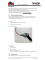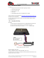
1
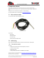
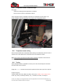
Accessory Installation Manual T23 Fleet Accessory Installation Manual v0.45 © 2007 - 2014 Tramigo™ Ltd. All rights reserved. Under the copyright laws, this manual cannot be reproduced in any form without the prior written permission of Tramigo™. Page 1 of 29 Accessory Installation Manual Contents 1. General...........................................................................................................4 1.1 Prior Installation testing and steps .................................................................4 2. Driver ID .........................................................................................................5 2.1 Parts and tools needed ....................................................................................5 2.2 Initial testing .....................................................................................................5 2.2.1 Parts and tools needed ................................................................................6 2.2.2 Assembly and testing ...................................................................................6 2.3 Configuration and commands .........................................................................7 2.3.1 Enabling Driver ID........................................................................................7 2.3.2 Showing Driver ID data on reports ...............................................................7 2.3.3 Adding a Driver ID user................................................................................8 2.3.4 Listing added drivers ....................................................................................8 2.3.5 Reading connected Driver ID data ...............................................................8 2.3.6 Deleting a driver...........................................................................................9 2.3.7 Deleting all drivers .......................................................................................9 2.4 Installation ........................................................................................................9 2.4.1 Driver ID reader location ..............................................................................9 2.4.2 Driver ID Reader installation steps ...............................................................9 2.4.3 Driver ID Reader wiring..............................................................................10 2.4.4 Testing .......................................................................................................10 2.5 Usage ..............................................................................................................11 2.6 Trouble shooting ............................................................................................11 3. Temperature Sensor ...................................................................................13 3.1 Parts and tools needed ..................................................................................13 3.2 Initial testing ...................................................................................................13 3.2.1 Parts and tools needed ..............................................................................13 3.2.2 Assembly and testing .................................................................................14 3.3 Configuration and commands .......................................................................15 3.3.1 Enabling Temperature Sensor ...................................................................15 3.3.2 Showing Temperature Sensor data on reports ...........................................15 3.3.3 Adding and naming Temperature Sensors .................................................16 3.3.4 Reading connected Temperature Sensors .................................................16 3.3.5 Reading single Temperature Sensor data ..................................................16 3.3.6 Temperature alarm.....................................................................................16 3.3.7 Deleting a sensor .......................................................................................17 3.3.8 Deleting all sensors....................................................................................17 3.4 Installation ......................................................................................................17 3.4.1 Temperature sensor installation steps........................................................18 © 2007 - 2014 Tramigo™ Ltd. All rights reserved. Under the copyright laws, this manual cannot be reproduced in any form without the prior written permission of Tramigo™. Page 2 of 29 Accessory Installation Manual 3.4.2 3.4.3 Temperature sensor wiring.........................................................................18 Testing .......................................................................................................18 3.5 Usage ..............................................................................................................19 3.6 Trouble shooting ............................................................................................19 4. Analog Input ................................................................................................ 20 4.1 Initial Testing ..................................................................................................20 4.1.1 Parts and tools needed ..............................................................................20 4.1.2 Wiring and testing ......................................................................................20 4.2 Configuration and commands .......................................................................21 4.3 Installation ......................................................................................................21 4.4 Trouble shooting ............................................................................................21 5. 3rd Party Fuel Level Sensor ........................................................................22 5.1 Initial testing ...................................................................................................22 5.2 Configuration and commands .......................................................................22 5.2.1 Configuring the T23 Fleet...........................................................................22 5.3 Installation ......................................................................................................22 5.4 Usage ..............................................................................................................22 5.5 Trouble shooting ............................................................................................23 5.6 3rd Party fuel sensor suppliers ......................................................................23 6. Tramigo Fuel Level Measurement ............................................................. 24 6.1 Parts and tools needed ..................................................................................24 6.2 Initial testing ...................................................................................................24 6.3 Configuration and commands .......................................................................24 6.3.1 Measuring the fuel gauge voltage ..............................................................24 6.3.2 Configuring the T23 Fleet...........................................................................26 6.4 Installation ......................................................................................................27 6.4.1 Steps .........................................................................................................27 6.5 Usage ..............................................................................................................28 6.6 Trouble shooting ............................................................................................29 © 2007 - 2014 Tramigo™ Ltd. All rights reserved. Under the copyright laws, this manual cannot be reproduced in any form without the prior written permission of Tramigo™. Page 3 of 29 Accessory Installation Manual 1. General Instructions how to use and install Tramigo Rev B T23 Fleet professional accessories. Note: Use Firmware version 1.0.96 or newer. 1.1 Prior Installation testing and steps It is good practice to test new accessory at the office or other suitable place before heading to the installation location. Check that you have all parts and tools needed Verify that the accessory is working correctly You know how to use and operate the accessory Go through the installation steps and process in your mind Double check above before heading to the location This saves tons of valuable time and money, and increases end user/customer satisfaction. © 2007 - 2014 Tramigo™ Ltd. All rights reserved. Under the copyright laws, this manual cannot be reproduced in any form without the prior written permission of Tramigo™. Page 4 of 29 Accessory Installation Manual 2. Driver ID With Tramigo Driver ID solution fleet owners can monitor current driver ID and collect data to server. Driver ID SMS message reporting is supported as well. Driver ID utilizes Maxim Integrated™ 1-Wire technology. With 1-Wire it is possible to connect several 1-wire accessories to one Tramigo T23 Fleet 1-Wire interface. For more information about 1-Wire please see www.maximintegrated.com 2.1 Parts and tools needed You need following Tramigo Driver ID system parts. They come with Tramigo Driver ID accessory package. One Driver ID reader is needed per vehicle and maximum number of Driver IDs configured in T23 Fleet device is 10. Parts needed: Driver ID reader, the driver ID fob button reader Driver ID buttons (fob), the ID key See image of parts below. Driver ID Magnetic Reader and Driver ID fob Tools needed: Wire cutters Pliers and wrench Automotive tape Cable connectors and spare wire Drill and 8 mm drill head, 7mm if plastic surface and able to twist the reader into hole 2.2 Initial testing How to verify that Driver ID Accessory and T23 Fleet are in working order. © 2007 - 2014 Tramigo™ Ltd. All rights reserved. Under the copyright laws, this manual cannot be reproduced in any form without the prior written permission of Tramigo™. Page 5 of 29 Accessory Installation Manual 2.2.1 Parts and tools needed You need: Tramigo T23 Fleet device with Firmware supporting 1-Wire bus 12 wires T23 Fleet IO cable Driver ID magnetic reader Driver ID fob Tramigo Manager (TM) version 3.0 installed into PC or laptop Tramigo manager can be downloaded from www.tramigo.net/tramigomanager/tmanager.asp with the link to TM 3 User Manual. If you are missing some parts, please contact to your nearest Tramigo reseller or email to [email protected] 2.2.2 Assembly and testing Easy steps: 1. Connect the Driver ID reader BLACK wire to IO cable BLACK ground wire #3 or #4 2. Connect the Driver ID reader RED wire to IO cable WHITE wire pin #12 3. Insert the fob in reader and give a command ListOneWire via TM3 or SMS Driver ID reader connected to T23 Fleet Response example, TM 3 screen: Tramigo: ListOneWire, Driver (ID: 12981719201ABC), 18:57 Jul 19 The number shown is the unique for each Driver ID fob used, later are instructions how it can be paired with the driver’s real name. © 2007 - 2014 Tramigo™ Ltd. All rights reserved. Under the copyright laws, this manual cannot be reproduced in any form without the prior written permission of Tramigo™. Page 6 of 29 Accessory Installation Manual If there is an error on reading, response is: Tramigo: ListOneWire, error, devices not found, 18:57 Jul 19 In this case, try at least 3 times and verify that fob is firmly in place and wiring is correct. If problem persist, please refer to troubleshooting section later on this document. 2.3 Configuration and commands You can add maximum of 10 Driver ID and driver name pairs into T23 Fleet device. 2.3.1 Enabling Driver ID Enabling periodic detection and reading of Driver ID. Set command parameters: Set,DriverEnable,0/1 0 - Disable periodic detection and reading 1 - Enable periodic detection and reading Example: Set,DriverEnable,1 2.3.2 Showing Driver ID data on reports Showing Driver ID data on Status report messages. Set command parameters: Set,ShowDriver,0/1/2/3 0 – Driver ID data not shown 1 – Driver name only, if name is not stored, Driver ID number is shown 2 – Driver ID number only 3 – Driver name and Driver ID number Example: Set,ShowDriver,2 Response: Tramigo: Set, parameter ShowDriver, value 2, 08:57 May 9 Notes: 1. SET affects to Status, Ignition and Speed report and to all registered users. 2. Not affecting Driver ID data when querying it from the T23 Fleet device memory. © 2007 - 2014 Tramigo™ Ltd. All rights reserved. Under the copyright laws, this manual cannot be reproduced in any form without the prior written permission of Tramigo™. Page 7 of 29 Accessory Installation Manual Get current parameter value: Example: Get,ShowDriver Response: Tramigo: Get, parameter ShowDriver, value 2, 08:57 May 9 2.3.3 Adding a Driver ID user Example command: Driver,Add,123456ABD231278,Jane Doe Response: Tramigo: Driver, Jane Doe (123456ABD231278) has been added, 08:57 May 9 Notes and tips: 1. Good practice is to create Configuration File (CF) with commands for all drivers to be added into particular vehicle’s T23 Fleet device 2.3.4 Listing added drivers Example command: Driver,List Response: Tramigo: Driver, Jane Doe (123456ABD231278), Mark Hamilton (123345356ABD231278), Hans Wik (123236SCA231278), 08:57 May 9 Notes and tips: 1. Listing comes from the T23 Fleet device memory, not from the reader 2. The fob’s Driver ID number can be get with ListOneWire command when on reader 3. If problems please refer to troubleshooting section 2.3.5 Reading connected Driver ID data When Driver ID fob is placed in reader, you can read the ID number and name pair. Example command: Driver Response: Tramigo: Driver, Jane Doe (123456ABD231278), 08:57 May 12 Notes and tips: 1. If fob is not in reader correctly, it returns ”error, driver not found” 2. Can be also used to get fob Driver ID number © 2007 - 2014 Tramigo™ Ltd. All rights reserved. Under the copyright laws, this manual cannot be reproduced in any form without the prior written permission of Tramigo™. Page 8 of 29 Accessory Installation Manual 2.3.6 Deleting a driver Example commands: Driver,Del,Jane Doe Driver,Del,123456ABD231278 Response: Tramigo: Driver, Jane Doe (123456ABD231278), 08:57 May 9 Notes: 1. Driver deleted from T23 fleet memory 2.3.7 Deleting all drivers Example: Driver,Del,All Response: Tramigo: Driver, All drivers deleted, 08:57 May 9 Notes: 1. Drivers deleted from unit memory Response: Tramigo: Set, parameter DriverEnable, value 1, 08:57 May 9 2.4 2.4.1 Installation Driver ID reader location Locate suitable place from the vehicle’s dash board. It should be a place where driver’s hands or legs are not likely to touch when operating the vehicle. 2.4.2 Driver ID Reader installation steps Easy steps: 1. Use drill a 8 mm hole on selected location 2. Loose the nut and insert the Driver ID reader to the hole 3. Screw the nut back on the reader and tighten the nut firmly After Driver ID reader is installed it should look for example like in picture below: © 2007 - 2014 Tramigo™ Ltd. All rights reserved. Under the copyright laws, this manual cannot be reproduced in any form without the prior written permission of Tramigo™. Page 9 of 29 Accessory Installation Manual Driver ID reader installed 2.4.3 Driver ID Reader wiring Refer to section earlier where Driver ID Reader wiring to T23 Fleet device and wire colors is explained. The same applies when Driver ID accessory is installed into vehicle. Note: Good common ground with T23 Fleet device is essential. Ground the Driver ID reader with T23 Fleet device grounding point. 2.4.4 Testing After Driver ID accessory is installed into vehicle you can test it functionality with the Driver ID commands described earlier in this document. Supply the Status command when fob in reader and verify that driver ID is part of the response. Example response: Tramigo: Status: GPS: 83%, GSM: 0%, Temperature: 41.59 C, battery: 99% (4.20 V), ID: Jane Doe (123456ABD231278), Power, Trip, Find (1,0.5,360,40), Status (5,-,30,-), 14.55934, 121.01943, 15:16 May 14 Note: 1. Check and verify that vehicle’s signal lights and meters are working before the accessory is installed 2. Check and verify that vehicle’s signal lights and meters are working after the accessory is installed and tested © 2007 - 2014 Tramigo™ Ltd. All rights reserved. Under the copyright laws, this manual cannot be reproduced in any form without the prior written permission of Tramigo™. Page 10 of 29 Accessory Installation Manual 2.5 Usage Important note: Driver ID fob has to be placed in reader when driver is driving the vehicle. Tramigo Driver ID is magnetic reader and fob will stick to it. Most common way of reporting Driver ID data: Important note: Driver ID fob has to be in reader during the whole time the driver is 1. Enabling Driver ID data on Status, Ignition and Speed reports driving the vehicle. Tramigo Driver ID is magnetic reader and fob will stick to it. 2. Collecting Driver ID data via GPRS M2M message (Refer to Tramigo GPRS guide.) 3. One time query with Driver command Important note: Driver ID fob has to be in reader during the whole time the driver is driving the vehicle. Tramigo Driver ID is magnetic reader and fob will stick to it. Option 1 is suitable for fleet owners using M1 Fleet Enterprise GPRS- or M1 Move with SMS reporting. Important note: Driver ID fob has to be in reader during the whole time the driver is Option 2 for fleet owners using M1 Fleet Enterprise with GPRS data reporting. driving the vehicle. Tramigo Driver ID is magnetic reader and fob will stick to it. Option 3 mainly for asking current drivers with single SMS message or testing purposes. 2.6 Trouble shooting Cannot read the driver ID number from the fob. 1. Check that wirings are correct 2. Check with another fob, is the fob possible damaged 3. Use common commands like ListOneWire or Driver 4. If not reporting even “no driver”, check the T23 Fleet FW version, it should be 1.0.96 or above. Driver ID number or data not seen on report message. 1. If reporting “No Driver” check the wiring 2. If still no success, try another fob 3. Check that you have supplied correct SET commands to enable reporting No Driver ID shown (neither Temperature Sensor data if installed) 1. Check that there is a gap on fob as shown in picture below 2. Check that there are no metallic parts stuck neither on the magnetic reader nor the fob Above might cause a short circuit and T23 Fleet is unable to read any 1-Wire bus data. © 2007 - 2014 Tramigo™ Ltd. All rights reserved. Under the copyright laws, this manual cannot be reproduced in any form without the prior written permission of Tramigo™. Page 11 of 29 Accessory Installation Manual How to detect defective fob © 2007 - 2014 Tramigo™ Ltd. All rights reserved. Under the copyright laws, this manual cannot be reproduced in any form without the prior written permission of Tramigo™. Page 12 of 29 Accessory Installation Manual 3. Temperature Sensor With Tramigo Temperature Sensor solution fleet owners can monitor vehicle and cargo temperatures and collect data to server. Temperature SMS message reporting is supported as well. Temperature sensors utilize Maxim Integrated™ 1-Wire technology. For more information about 1-Wire please see www.maximintegrated.com 3.1 Parts and tools needed You only need Tramigo 1-Wire Temperature Sensor. Temperature Sensor Tools needed: Wire cutters Pliers and wrench Automotive tape Cable connectors and spare cable 3.2 Initial testing How to verify that Temperature Sensor Accessory and T23 Fleet are in working order. 3.2.1 Parts and tools needed You need: Tramigo T23 Fleet device with Firmware supporting 1-Wire bus 12 wires T23 Fleet IO cable Temperature Sensor Tramigo Manager (TM) version 3.0 installed into PC or laptop Tramigo manager can be downloaded from www.tramigo.net/tramigomanager/tmanager.asp with the link to TM 3 User Manual. © 2007 - 2014 Tramigo™ Ltd. All rights reserved. Under the copyright laws, this manual cannot be reproduced in any form without the prior written permission of Tramigo™. Page 13 of 29 Accessory Installation Manual If questions, please contact to your nearest Tramigo reseller or email to [email protected] 3.2.2 Assembly and testing Temperature sensor comes with three wires. Usually YELLOW or WHITE wire is the 1-Wire bus cable. RED cable is the auxiliary power line. Extra power may be needed if attaching 3 sensors, cable length is over 10 meters per senor and measuring ≥100 °C temperatures. Auxiliary power range is 3.0 – 5.25 VDC. BLACK wire is connected to vehicle Ground. Note: When auxiliary power is not needed both RED and BLACK wire is connected to the vehicle Ground. Easy steps: 1. Connect the sensor’s BLACK and RED wire to IO cable BLACK ground wire #3 or #4 2. Connect the sensor’s WHITE or YELLOW wire to IO cable WHITE wire pin #12 3. Give a command Set,TempSensorEnable,1 and TempSensor via TM3 or SMS Temperature Sensor connected to T23 Fleet Response example, TM 3 screen: Tramigo: TempSensor, TempSensor1: 31.43 C (2832E497050000), 02:12 Nov 11 Later are instructions how sensors can be named and configured. If there is an error on reading, response is: Tramigo: TempSensor, error, not found, 18:57 Jul 19 In this case, try at least 3 times and verify that wiring is correct. If problem persist, please refer to troubleshooting section later on this document. © 2007 - 2014 Tramigo™ Ltd. All rights reserved. Under the copyright laws, this manual cannot be reproduced in any form without the prior written permission of Tramigo™. Page 14 of 29 Accessory Installation Manual 3.3 Configuration and commands You can add maximum of 3 Temperature Sensor and sensor name pairs into T23 Fleet device. 3.3.1 Enabling Temperature Sensor Enabling periodic detection and reading of Temperature Sensors. Set command parameters: Set, TempSensorEnable,0/1 0 - Disable periodic detection and reading 1 - Enable periodic detection and reading Example: Set, TempSensorEnable,1 Response: Tramigo: Set, parameter TempSensorEnable, value 1, 08:57 May 9 3.3.2 Showing Temperature Sensor data on reports Showing Temperature Sensor data on Status report messages. Set command parameters: Set,ShowTempSensor,0/1/2 0 Sensor(s) Not shown 1 Sensor(s) Name and Value shown 2 Sensor(s) Name, Value and ID shown Example: Set,ShowTempSensor,2 Response: Tramigo: Set, parameter ShowTempSensor, value 2, 08:57 May 9 Notes: 1. SET affects only to Status message data. Get current parameter value: Example: Get,ShowTempSensor Response: Tramigo: Get, parameter ShowTempSensor, value 2, 08:57 May 9 © 2007 - 2014 Tramigo™ Ltd. All rights reserved. Under the copyright laws, this manual cannot be reproduced in any form without the prior written permission of Tramigo™. Page 15 of 29 Accessory Installation Manual 3.3.3 Adding and naming Temperature Sensors 1. First find the Temperature Senor’s unique ID number. Example Command: ListOneWire Response Tramigo: ListOneWire, TempSensor (ID: 12652398171920), 08:57 May 9 2. Then pair the sensor’s ID number with desired name. Example command: TempSensor,Add,12652398171920,Chiller Response: Tramigo: TempSensor, Chiller has been added, 08:57 May 9 Notes and tips: 1. Good practice is to create Configuration File (CF) with commands for all temperature sensor to be added into particular vehicle’s T23 Fleet device 3.3.4 Reading connected Temperature Sensors Example: TempSensor Response: Tramigo: TempSensor, Chiller -2.06 C (12652398171920), Cargo 9.09 C (42652598171923), 08:57 May 9 3.3.5 Reading single Temperature Sensor data Example: TempSensor,Chiller Response: Tramigo: TempSensor, Chiller: -2.45 C (12652398171920), 08:57 May 9 3.3.6 Temperature alarm Setting the limits. Example: TempSensor,Chiller,Max,40 TempSensor,Chiller,Min,20 Response: Tramigo: TempSensor, Chiller: maximum limit 40 C, alarm when above, 08:57 May 9 Tramigo: TempSensor, Chiller: minimum limit 20 C, alarm when below, 08:57 May 9 Turning the alarm on or off. Example: © 2007 - 2014 Tramigo™ Ltd. All rights reserved. Under the copyright laws, this manual cannot be reproduced in any form without the prior written permission of Tramigo™. Page 16 of 29 Accessory Installation Manual TempSensor,Chiller,On TempSensor,Chiller,Off Response: Tramigo: TempSensor, Chiller alarm, reporting is turned on, 08:57 May 9 Tramigo: TempSensor, Chiller alarm, reporting is turned off, 08:57 May 9 Report: Tramigo: Alarm detected, TempSensor, Chiller: 19 C, temperature below 20 C, parked, at Valero Street-Rufino Street, Makati, NCR, PH, 14.55954, 121.01953, 11:55:39 May 14 To see the values set use command TempSensor,Chiller,Min or Max Notes: 1. If alarm is activated and there are no sensor detected or connected to the unit it will display “not found”. 2. One limit, above or below alarm, simply set both Minimum and Maximum to same value. 3.3.7 Deleting a sensor Example: TempSensor,Del,12652398171920 Response: Tramigo: TempSensor, Chiller (12652398171920) deleted, 08:57 May 9 Notes: 1. Deleted from unit’s memory, sensor may be still there, if not removed. 3.3.8 Deleting all sensors Example: TempSensor,Del,All Response: Tramigo: TempSensor, All Temperature Sensors deleted, 08:57 May 9 Notes: 1. Deleted from unit’s memory, sensor(s) may be still there, if not removed. 3.4 Installation Maximum number of Temperature Sensors configured in T23 Fleet device is 3. Temperature Sensors measurement range is from -55 °C to +125 °C. However, recommended range is from -25 °C to +100 °C. © 2007 - 2014 Tramigo™ Ltd. All rights reserved. Under the copyright laws, this manual cannot be reproduced in any form without the prior written permission of Tramigo™. Page 17 of 29 Accessory Installation Manual 3.4.1 Temperature sensor installation steps Easy steps: 1. Select the location(s) where temperature is measured. 2. Secure sensor in place for example with cable tie. After Temperature Sensor is installed it should look for example like in picture below. Use proper installation materials depending on the location of the Temperature Sensor. Temperature Sensor installed under dashboard 3.4.2 Temperature sensor wiring Refer to section earlier where Temperature Sensor wiring to T23 Fleet device and wire colors is explained. The same applies when Temperature Sensor is installed into vehicle. Note: Good common ground with T23 Fleet device is essential. Ground the sensor with T23 Fleet device grounding point. 3.4.3 Testing After Temperature Sensor is installed into vehicle you can test it functionality with commands described earlier in this document. Supply the Status command and verify that Temperature Sensor data is part of the response. Example response: Tramigo: Status: GPS: 83%, GSM: 0%, battery: 99% (4.20 V), Chiller: -6.78 C, Cargo: 5.34 C Power, Trip, Find (1,0.5,360,40), Status (5,-,30,-), 14.55934, 121.01943, 15:16 May 14 © 2007 - 2014 Tramigo™ Ltd. All rights reserved. Under the copyright laws, this manual cannot be reproduced in any form without the prior written permission of Tramigo™. Page 18 of 29 Accessory Installation Manual Note: 1. Check and verify that vehicle’s signal lights and meters are working before the accessory is installed. 2. Check and verify that vehicle’s signal lights and meters are working after the accessory is installed and tested. 3.5 Usage Most common way of reporting Temperature Sensor data: 1. Enabling sensor data on Status reports. 2. Collecting Sensor data via GPRS M2M message (Refer to Tramigo GPRS guide.). 3. One time query with TempSensor command. Option 1 is suitable for fleet owners using M1 Fleet Enterprise GPRS- or M1 Move with SMS reporting. Option 2 for fleet owners using M1 Fleet Enterprise with GPRS data reporting. Option 3 mainly for asking current temperatures with single SMS message or testing purposes. 3.6 Trouble shooting Cannot read the temperature data. 1. Check that wirings are correct. 2. Check with another sensor, is the sensor possible damaged. 3. Use common commands like ListOneWire or TempSensor. 4. If T23 is refusing the commands, check the T23 Fleet FW version, it should be 1.0.96 or above. Temperature data not seen on report message. 1. Check the wirings. 2. If still no success, try another sensor. 3. Check that you have supplied correct SET commands to enable reporting. Temperature Sensors show disconnected state 1. Check the wirings and connections. 2. Test with spare sensor is it working. 3. If Driver ID is used, check is it working: a. If not: Confirm that Driver ID is not short circuit. (Refer to Driver ID troubleshooting section.) b. If yes: Double check wirings, settings and sensors. False temperature readings 1. Check wirings and connections. 2. Test with spare sensor is it working. © 2007 - 2014 Tramigo™ Ltd. All rights reserved. Under the copyright laws, this manual cannot be reproduced in any form without the prior written permission of Tramigo™. Page 19 of 29 Accessory Installation Manual 4. Analog Input Tramigo T23 Fleet Analog Input can be used with various analog accessories and for analog measurements. In practice all accessories and devices which output data is in voltage range 0 30 VDC can be considered and utilized. Hints and Tips: Tramigo T23 Fleet has one (1) analog input; one device can be attached at one time. However, if just measuring plain voltage, you can use T23 Fleet output and relay to switch input coming from the device or accessory. For example if you are measuring two vehicle batteries voltage level, this can be done with above arrangement. 4.1 Initial Testing Familiarize with analog input and how to use it. 4.1.1 Parts and tools needed You need: Tramigo T23 Fleet device with Firmware supporting Analog input 12 wires T23 Fleet IO cable Voltage source, adjustable power source preferred but 1.5-12 V battery can be used Tramigo Manager version 3.0 (TM3) installed into PC or laptop Tramigo manager can be downloaded from www.tramigo.net/tramigomanager/tmanager.asp with the link to TM3 User Manual. If you are missing some parts, please contact to your nearest Tramigo reseller or email to [email protected] 4.1.2 Wiring and testing Easy steps: 1. Connect the voltage source ground to IO cable BLACK ground wire #3 or #4 2. Connect the voltage source positive to IO cable PINK wire pin #11 3. Give a command ReadAnalog via TM3 or SMS © 2007 - 2014 Tramigo™ Ltd. All rights reserved. Under the copyright laws, this manual cannot be reproduced in any form without the prior written permission of Tramigo™. Page 20 of 29 Accessory Installation Manual Voltage source connected to T23 Fleet Response example, TM3 screen: Tramigo: ReadAnalog, 12.723 V, 15:16 May 14 If there is an error on reading, response is: Tramigo: ReadAnalog, error, no analog voltage, 18:57 Jul 19 In this case, try at least 3 times and verify wiring is correct. If problem persist, please refer to troubleshooting section later on this document. 4.2 Configuration and commands Depending on the application, sensors and voltage source what is targeted to measure or observe, and what is the desired configuration and reports. 4.3 Installation rd When using 3 party analog sensors and devices refer to supplier’s manuals and guides. If measuring for example vehicle’s battery voltage simply connect the wire from the battery to the T23 Fleet’s analog input. Remind the applicable measurement range of 0 – 30 VDC. 4.4 Trouble shooting Cannot get analog reading 1. Check that wirings are correct and intact. 2. If T23 is refusing the commands, check the T23 Fleet FW version, it should be 1.0.96 or above © 2007 - 2014 Tramigo™ Ltd. All rights reserved. Under the copyright laws, this manual cannot be reproduced in any form without the prior written permission of Tramigo™. Page 21 of 29 Accessory Installation Manual 5. 3rd Party Fuel Level Sensor Possible to connect any analog fuel level sensor with 0 - 30 VDC output voltage. 5.1 Initial testing Note: Refer to sensor supplier’s set-up, calibration, testing and installation manuals and guides. Fuel level sensor voltage output can be tested when tank has different fuel levels. Most convenient would be fill up the empty fuel tank and check the readings. 5.2 Configuration and commands In most of the cases sensors output curve is linear (straight line), hence the minimum set of voltage-percentage pairs is 2; tank empty 0% and tank full 100%, if the shape of the tank is uniform. Perform possible testing and measurement when vehicle is in level and fuel is not moving inside the tank. Wait until output voltage is not changing after adding fuel in the tank. Refer the sensor supplier’s guide regarding the voltage ranges and calibration. 5.2.1 Configuring the T23 Fleet Refer to configuration steps explained in section 6.3.2 Configuring the T23 Fleet. As explained above, fuel sensor curve is most likely linear, hence fewer voltage – percentage pairs needed. Note: With external fuel level sensor it is most likely empty tank voltage is smaller than when tank is full, for example: Empty tank 0.00 VDC and full tank 5.00 VDC. 5.3 Installation Refer to supplier’s manuals and guides. 5.4 Usage Most common way of reporting fuel level sensor data: 1. Enabling fuel level data on Status and Ignition reports. 2. Collecting data via GPRS M2M message (Refer to Tramigo GPRS guide.). 3. One time query with ReadAnalog command. Option 1 is suitable for fleet owners using M1 Fleet Enterprise GPRS- or M1 Move with SMS reporting. Option 2 for fleet owners using M1 Fleet Enterprise with GPRS data reporting. Option 3 mainly for asking current fuel level with single SMS message or testing purposes. Fuel theft (shiphoning) alarm can be enabled for any registered user, incluging GPRS. © 2007 - 2014 Tramigo™ Ltd. All rights reserved. Under the copyright laws, this manual cannot be reproduced in any form without the prior written permission of Tramigo™. Page 22 of 29 Accessory Installation Manual 5.5 Trouble shooting Note: Refer to supplier’s documentation and guidance. Cannot read the analog fuel level data. 1. Check that wirings are correct and intact. 2. Good grounding is essential, sensor ground and T23 Fleet ground preferably from the same point. 3. Check with multimeter that sensor is outputting voltage when vehicle ignition is on. 4. Use common commands like ReadAnalog. 5. Check that you have supplied correct SET commands to enable reporting. 6. If T23 Fleet is refusing the commands, check the T23 Fleet FW version, it should be 1.0.96 or above. 5.6 3rd Party fuel sensor suppliers There are several suppliers on market. Here is one supplier’s data. Mr. Maxim Gutsalo, Sales Manager RCS-NAVIGATION LTD 2/6 E Novozabarska Str. 04074 Kiev, Ukraine Tel: 044 206 69 79 Fax: 044 206 42 34 Mobile: +38 093 887 46 26 Skype: maximus2867 Email: [email protected] © 2007 - 2014 Tramigo™ Ltd. All rights reserved. Under the copyright laws, this manual cannot be reproduced in any form without the prior written permission of Tramigo™. Page 23 of 29 Accessory Installation Manual 6. Tramigo Fuel Level Measurement 6.1 Parts and tools needed Parts needed: No parts needed. Vehicle’s fuel gauge analog voltage signal is wired to T23 Fleet analog input pin #11. Tools needed: 1. Wire cutters 2. Pliers and wrench 3. Automotive tape 4. Cable connectors, posi-taps and spare wire 6.2 Initial testing Note: Familiarize yourself with analog input functionality and commands before actual vehicle installations. Saves time and resources. 6.3 6.3.1 Configuration and commands Measuring the fuel gauge voltage Fuel gauge voltage output levels can be tested when tank has different fuel levels. Most convenient would be fill up the empty fuel tank and record the readings. Read and follow instructions listed on below carefully. Disconnect the vehicle’s battery during the wiring the T23 Fleet to vehicle’s fuel gauge to avoid short circuits. Note: Double check your wirings and connections before connecting vehicle battery or turning the ignition on. Use posi-tap or similar wire connection methods, do not cut the vehicle’s analog voltage wire. Vehicle shall be in level, not tilted. When taking the measurements, vehicle ignition should be on, it powers the fuel gauge. It is most likely that resulting line is not linear, hence multiple readings are needed. Note that most of the fuel gauges outputs minimum voltage when tank is full and maximum voltage when tank is empty. Recommended to take voltage reading minimum per every 10 liters added. Use multimeter or T23 Fleet unit and command ReadAnalog. Between the fillings and taking the reading, wait until fuel is not moving inside the tank. Depending on gauge model there may be filtering in place. After adding fuel, wait until measured voltage is not changing (up till 1 - 4 minutes). © 2007 - 2014 Tramigo™ Ltd. All rights reserved. Under the copyright laws, this manual cannot be reproduced in any form without the prior written permission of Tramigo™. Page 24 of 29 Accessory Installation Manual Below is example of Honda CRV 1998 measurements, multiple measurement points. Liters Voltage 0 3.16 1 3.04 2 2.98 3 2.86 4 2.73 5 2.58 6 2.5 7 2.43 8 2.36 9 2.29 10 2.22 17 1.85 27 1.64 37 1.2 47 0.4 52.28 0.37 Liters – Voltage pairs Measurement pairs print the curve shown below. Measurements curve Liters – Voltage As can be seen on above picture, the curve is not linear. T23 Fleet has in-build smart functionality which calculates the fuel volume between the measurement points. © 2007 - 2014 Tramigo™ Ltd. All rights reserved. Under the copyright laws, this manual cannot be reproduced in any form without the prior written permission of Tramigo™. Page 25 of 29 Accessory Installation Manual 6.3.2 Configuring the T23 Fleet Below is shown example configuration commands and procedure for vehicle which fuel tank capacity is 85 liters, outputting 0.5 VDC when tank is full and 3.8 VDC when tank is empty. Naturally, use capacity and measurements of the vehicle under installation. For complete set of commands, how to list, delete and edit, refer to “T23F_AIS_Analog_Input_Specification_ENG_v0.3_FUEL” document Example Comfiguration: // Set the minimum and maximum voltage, tank full (100%) and tank empty (0%) ANALOG,MINVOLTAGE,3.8 ANALOG,MAXVOLTAGE,0.5 // Add voltage - percentage pairs. Especially if voltage curve is not linear // Important: Percentage % values use integer (whole numbers) values only ANALOG,ADD,80,0.7 ANALOG,ADD,60,1.05 // ...more points here ANALOG,ADD,10,3.65 // Check that voltage - percentage pairs are correct ANALOG,LIST // Set the moving average window. This will smooth the analog voltage reading measured. // 5 = reading interval in seconds, 20 = number of readings from moving average is calculated // Minimum interval value is 5 sec. Maximum interval value is 600 sec. // Minimum number of readings is 1 (no averaging). Maximum is 30 readings. ANALOG,INTERVAL,5,20 // NOTE: with above setting it takes approx. 5 x 20s = 100 seconds to have correct averaged // voltage when Ignition is turned on. // READANALOG -command can be used to read current voltage without averaging. // Set the unit literal. Not needed, if only voltage value needed on reports ANALOG,UNIT,Liters // Range in order to show remaining fuel capacity, refers to SET function option 3. ANALOG,MAXRANGE,85 ANALOG,MINRANGE,0 // SET,SHOWANALOG,0/1/2/3 // Set how fuel level is shown in reports // 0 - not shown, affects only Status and Ignition report © 2007 - 2014 Tramigo™ Ltd. All rights reserved. Under the copyright laws, this manual cannot be reproduced in any form without the prior written permission of Tramigo™. Page 26 of 29 Accessory Installation Manual // 1 - Analog voltage only (Default) // 2 - Analog voltage and percent value // 3 - Value in volume unit given and percent SET,SHOWANALOG,3 // SET,ANALOGENABLE,0/1 // Enable analog data periodic reading // 0 - Disable periodic reading of analog input // 1 - Enable periodic reading of analog input SET,ANALOGENABLE,1 // Setting the fuel theft (siphoning) alarm // 10 = percentage % change in fuel level, 300 = % change happened in 300 seconds period // BELOW = volume was decreased ANALOG,FuelTheft,10,300,BELOW FuelTheft,ON // Reporting: Used as normal, for example REPORT,2,FuelTheft,ON // Disable reporting "FuelTheft,OFF // Setting the alarm rearm delay time // Set this value higher than the analog alarm time divided by analog reading value. // In this case 300s / 20 = 15 seconds. SET,ANALOGALARMREARMDELAY,20 Hint: You can integrate your settings to your Configuration (CF) file. 6.4 Installation The location, shape and size of the vehicle’s fuel gauge depends on the make and model.If possible, study and inspect the vehicle make and model before the installation so it is easier to locate the fuel gauge and the wire that bears the fuel level analog voltage. 6.4.1 Steps 1. Disconnect the vehicle’s battery during the installation and wiring to avoid short circuits. Connect battery only when performing measurements or testing the functionality. 2. Locate the fuel gauge. It is usually on the top of the tank.See picture below. © 2007 - 2014 Tramigo™ Ltd. All rights reserved. Under the copyright laws, this manual cannot be reproduced in any form without the prior written permission of Tramigo™. Page 27 of 29 Accessory Installation Manual 3. Note: Many cases you can locate the same wire running under panel next to drivers seat. Locate the same color wire and check that the voltage is the same as in a wire on fuel gauge. This way no need to run the cable from fuel tank. 4. Connect T23 Fleet IO cable PINK wire #11 to Analog Voltage wire coming from the fuel gauge. Note: If you are using previous T23 IO cable type, you should have full 11 wires model. The color of the wire #11 can be PINK w/ BLACK stripe or GREEN. Use posi-tap or similar methods, do not cut the vehicle’s fuel gauge wires. 5. Note: Double check your wirings and connections before connecting vehicle battery or turning the ignition on. 6. Measure the voltage with command ReadAnalog when vehicle ignition is OFF. It should be 0.0 V. 7. Measure the voltage with command ReadAnalog when vehicle ignition is ON. It should be within the minimum and maximum voltage limits. 8. T23 Fleet should be already configured in as instructed earlier in section 6.3.2 Configuring the T23 Fleet. Use the Status command to see is reporting correct. 9. Secure wiring and connections using automotive grade tape, adhesives, cable tie, positaps and crimps (buts). 6.5 Usage Most common way of reporting fuel level data: 1. Enabling fuel level data on Status and Ignition reports. 2. Collecting data via GPRS M2M message (Refer to Tramigo GPRS guide.). 3. One time query with ReadAnalog command. © 2007 - 2014 Tramigo™ Ltd. All rights reserved. Under the copyright laws, this manual cannot be reproduced in any form without the prior written permission of Tramigo™. Page 28 of 29 Accessory Installation Manual Option 1 is suitable for fleet owners using M1 Fleet Enterprise GPRS- or M1 Move with SMS reporting. Option 2 for fleet owners using M1 Fleet Enterprise with GPRS data reporting. Option 3 mainly for asking current fuel level with single SMS message or testing purposes. Fuel theft (shiphoning) alarm can be enabled for any registered user, incluging GPRS. 6.6 Trouble shooting Cannot read the analog fuel level data. 1. Check that wirings are correct and intact. 2. Good grounding is essential, check T23 Fleet grounding. 3. Check with multimeter that sensor is outputting voltage when vehicle ignition is on. 4. Use common commands like ReadAnalog. 5. Check that you have supplied correct SET commands to enable reporting. 6. If T23 Fleet is refusing the commands, check the T23 Fleet FW version, it should be 1.0.96 or above. © 2007 - 2014 Tramigo™ Ltd. All rights reserved. Under the copyright laws, this manual cannot be reproduced in any form without the prior written permission of Tramigo™. Page 29 of 29