1
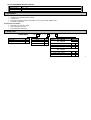
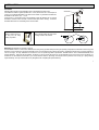
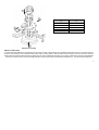
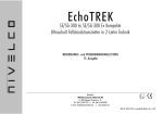
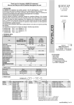
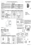
USER’S MANUAL Programming of the units is to perform according to the 3d edition of the INSTALLATION and PROGRAMMING MANUAL 2 DIST Far end blocking DEFAULT value of: P06=0 Displayable range Programmed measurement range application(H) Programmed value of P04=H Max. measuring range of the device Max. measuring distance of the device (X M ) DEFAULT value of P04=X M Close end blocking (XB) progr. value of P05=XB>Xm DEFAULT value of P05=Xm Min. meas. distance (Xm) PRINCIPLES ULTRASONIC LEVEL MEASUREMENT Angle of repose DIST=distance (measured) LEV=( level calculated H-DIST) VOL= volume (calculated from LEV) Thank you for choosing a NIVELCO instrument. We are sure that you will be satisfied throughout its use. 1. APPLICATION APPLICATION The EchoTREK SBD/STD-300 series compact ultrasonic transmitters from NIVELCO are designed to measure the level of the most free flowing solids (powders and granules). This intelligent microprocessor based smart level transmitter offers scaleable 4-20 mA output, programmable relay and HART communication. Level measurement technology based on the non-contacting ultrasonic principle is especially suited for applications where, for any reason, no physical contact can be established to the surface of the material to be measured and/or moving parts are to be avoided to eliminate mechanical wear-out. PRINCIPLE OF OPERATION X X The ultrasonic level metering technology is based on the principle of measuring the time required for the ultrasound pulses to make a round trip from the sensor to the level to be measured and back. The sensor emits an ultrasonic pulse train and receives the echoes reflected. The intelligent electronic device processes the received signal by selecting the echo reflected by the surface and calculates from the time of flight the distance between the sensor and the surface which constitutes the basis of all output signals of the EchoTREK! D r D 5m 10 m 0,7 m 1,2 m 20 m 2m 30 m 3m 40 m 3,8 m 50 m 4,7 m Diameters corresponding.to 5° beam angle A Total beam angle of 5° at –3 dB is a feature of all Nivelco’s ultrasonic sensors designed for the level measurement of free flowing solids. This uniquely narrow beam angle ensures reliable measurement in narrow silos with uneven side walls or sometimes even in the presence of dusting. Furthermore, as a result of the narrow beam angle – the emitted ultrasonic signals have an outstanding focusing – a sufficient signal penetration through dust is ensured. Minimum measuring distance (Xm): (also known as the “Dead Band”) is a feature common to all ultrasonic level meters. This is a short range in front of the sensor within which the ultrasonic device can not measure. Maximum measuring distance (XM): The longest range under ideal condition within which the device can measure. No measurement is possible beyond this distance. 3 2. TECHNICAL DATA GENERAL DATA Product name EchoTREK STD/SBD-300 series Sensor material Closed cell Polyurethane foam sensor face (PUR), Polypropylene sensor housing, Aluminium mounting accessories Housing material Powder paint coated Aluminium Process temperature -30°C ... +75°C Ambient temperature -30°C ... +60°C, with SAP-100 programming module -25°C ... +60°C Pressure (Absolute.) 0.7 ... 1.1 bar (0,07 ... 0,11 MPa) and ± 0.1 bar (0.01 MPa) difference between outside and internal silo space Mechanical protection Accuracy* Sensor: IP65 (NEMA 5), Housing: IP67 (NEMA 6) Version I: 120 … 375 V DC / 5,5 W 85 ... 255 V AC (50/60 Hz) / 6.8 VA ; Version II: 11.4 ... 40 V DC / 4.1 W 11.4 ... 28 V AC (50/60 Hz) / 4.6 VA ± (0.2% of the measured distance plus 0.1% of the maximum measuring distance of the device) Resolution 10 mm Outputs Analogue: 4 … 20 mA, max. 600 Ohm, galvanically isolated, overvoltage protection Power supply / Consumption Relay: SPDT, 250 V AC / 3 A, AC1 Display (SAP-100): 6 digits, icons and bargraph, Custom LCD Digital communication: HART, MODBUS Electrical protection Class I. Electrical connections 2 x M20x1.5 and 2 x ½” NPT for wire cross sections: 0.5 ... 2.5 mm2 * Under optimal circumstances of reflection and stabilised sensor temperature. TYPE SPECIFIC DATA Type STD-34J SBD-34J STD-33J SBD-33J STD-31J SBD-31J Maximum measuring distance* (XM) m/feet 15/49 30/98 60/196 Minimum measuring distance* (Xm) m/feet 0.6/2 0.6/2 1/3,33 Total beam angle (at -3dB) Measuring frequency Weight * Measured from the sensor face 4 5° 30 kHz 15 kHz 7 kg 10 kg SAP-100 PROGRAMMING AND DISPLAY MODULE Field indication 6 digits, icons and bargraph, Custom LCD Ambient temperature -25°C … +60°C Housing material PBT fibre-glass reinforced plastic, flame-retardant (DuPont) 2.1 ACCESSORIES • • • • • User’s Manual Installation and Programming Manual 3d edition Guarantee Card EView Light configuration software and description on CD (for types of SD- 3-3/4 only) 2 pcs M20x1.5 cable gland ACCESSORIES TO BE ORDERED • • • Split flange (order code: SFA – 35) SAP-100 programming module EView configuration software CD 2.2 ORDER CODES EchoTREK Typel Transmitter Transmitter + Local Indicator Code T B D – 3 S Range 60 m 30 m 15 m Code 1 3 4 J – Power supply / Output Version I. 120 … 255 V DC 85 … 255 V AC 4 … 20 mA + Relay 4 … 20 mA + Relay + HART RS 485 (MODBUS protocol) + Relay Version II. 11,4 … 40 V DC 11,4 … 28 V AC 4 … 20 mA + Relay 4 … 20 mA + Relay + HART RS 485 (MODBUS protocol) + Relay Code Stand. Ex 1 3 A 5 7 E 2 4 B 6 8 F 5 2.3 DIMENSIONS Ball-joint housing SD-33J- SD-33X- (view from above) SD-34J- SD-34X- ~8 2 4 ∅ 125 max.855 max.814 Ball-joint housing ø 14 m ax.20 6 ~ 840 Ball-joint housing SD-31J SD-31X- ° 8 3 ø 29 max.2 0 ° 3. INSTALLATION POSITIONING Selecting optimal location for the transmitter various considerations should be made. If the measured material is granule (material size > 5 mm) and the tank roof is dome shaped or conical, do not install the transmitter in the centre of the tank/silo. In general the transmitter can be installed on the radius r= (0,3 … 0,5) R. Avoid that the 5° conical beam angle of the transmitter contact the tank/silo wall. In case the transmitter is mounted close to the wall, it should be tilted (See section “Aiming”). Protect the transmitter electronics from overheating due to direct sunshine.. Sunshade r R GRAVITY FILLING PNEUMATIC FILLING Select a location that is as far away from the filling point(s) as possible. Select a location where the speed of the in-flowing material is the smallest. Suggested location (view from above) 40 m 3,8 m 50 m 4,7 m MOUNTING (See illustration for mounting on page 9) The EchoTREK consists of a sensor that is attached to the aiming arm (a pipe with a ball-joint housing incorporating a ball joint) that is attached to the housing of the electronics. It is recommended to mount the transmitter on the roof of the tank/silo using a flange (See drawing). The Ball-joint housing has a screw-hole diameter of 125 mm for fixing it. For easy installation we recommend to use our special flange with a split insertion, available with four sizes of DN125/150/200/300 (to be ordered separately). Removing the split insertion, the flange is to be put around the aiming arm and the ball-joint housing is to be fixed to the split flange. It is essential to use the washers and the bolts (4 pcs each) delovered with the split flange. The ball-joint will be pressed to the housing by a spring allowing adjustment/aiming. The 4 pcs of M12 bolts has only be tightened after completing the adjustment/aiming. 7 Mounting EchoTREK versions S-33J and S-34J 1. Check the split flange for matching the bore-holes with that of the counter-flange on the silo 2. Remove the split insertion from the flange and put the flange around the aiming arm between the sensor and the Alu-base. 3. Slide the split insertion back to its place and screw the ball-joint housing to the flange with the 4 pcs M 12 bolts to such an extent that will allow free movement of the aiming arm through and tilting by the ball joint for the aiming process. 4. Pass the sensor through the opening cut on the roof and fasten the flange to its place. 5. Perform the aiming (See section “Aiming” below). 6. For fixing the position of the aiming arm tighten the 4 pcs M 12 bolts of the ball-joint housing (Max. 3.5 Nm). Mounting EchoTREK SD -31 versions, with silo/tank roof opening of ∅ 300 mm The procedure is the same as above but the flange dia is of DN300. Mounting EchoTREK SD -31 version with silo/tank roof opening less than ∅ 300 mm and the silo space is accessible from inside 1. 2. 3. 4. 5. 6. 7. 8. 9. Check the split flange for matching the bore-holes with that of the bolt places or counter-flange on the silo Place the sealing below the flange (if necessary) Push the unit out of the silo (upwards) (See c on the next page) Is the Alu-base with the ball-joint over the counter-flange the special flange has to be placed around the aiming arm (See d on the next page) Put the split flange on the counter-flange and lower the ball-joint housing on it Slide the insertion to its place (Seee on the next page) Screw in the 4 pcs of M12 bolts (See fon the next page) to such an extent that will allow free aiming Fasten the EhoTREK (with the split flange) to the counter-flange or to the roof of the silo/tank. After completing aiming tighten the 4 pcs 12M bolts (Max. 3.5 Nm). If the entire tilting range of the aiming arm is required, the thickness of the roof can not exceed as specified on the above drawing. The EchoTREK can also be mounted on existing (manhole) covers, access lids or for instance on a steel structure lowered into a larger (ex.: 0.5 x 0.5 m) opening on the roof. This solution is to be used with roof stronger than 350 …380 mm. 8 Diameter of the opening D 160 mm 190 mm 230 mm 300 mm 340 mm Thickness of the roof V 110 mm 150 mm 200 mm 280 mm 300 mm Illustration for mounting AIMING OF THE ECHOTREK To reduce week signal reflection from the material surface caused by an angle of repose building due to the filling and/or emptying process, it is recommended to tilt the sensor by the aiming arm of the transmitter. Aiming is best carried out during operation, when the tank/silo is almost empty. In most cases, the sensor should be aimed towards the middle of the tank/silo bottom by aiming at the silo outlet. In applications where repose is not present or with tall and narrow silos (diameter/height 5) aiming is not critical: the sensor should face straight downwards. Aiming is also aided by the informational parameters P70 …P 75 (see Programming Manual). 9 Aiming should also be tested with full silo, since due to the great angle of repose the echo might be weak despite of the fact that level is near to the sensor. In such cases a reasonable compromise of aiming should be achieved that provide acceptable echo in every state of the filling. 4. ELECTRICAL CONNECTIONS • Earthing screw To access the electric connection point, unscrew the bolt on the side of the electronics housing. Use cable with a wire cross- section of 0.5 … 2.5 mm2. Place of M20x1.5 • Electric connections may be carried out by using a single or two cables. Wires NPT1/2" in different groups (A, B, C; shown below) must not be led in the same cable. Group A Low voltage power supply Low voltage for the relay Group B Group C 4 … 20 mA. Selv voltage power supply Selv voltage power or logic signal for the relay RS485 (shielded twisted pair) NPT1/2" 4...20 mA or RS 485 output (A) (B) + Power supply L1 N (+) ( ) - - 7 6 7 6 7 A • Devices must be grounded either at the internal or external grounding screw terminals depending on the way of cabling. • DC powered devices can be 3-wire connected. In this case the terminals ”1” and ”6” must be interconnected. In this case the galvanic isolation will not be provided! • After performing the electric connections, check for correct sealing and close the housing. 10 6 2 1 5 3 4 L+ L B 0 1 Relay output 5 4 3 2 3 4 5 6 7 8 2 1 2 1 LN 9 c d 5 4 3 Wiring diagramme Space for the wiring, for better overview without upper part 5. PROGRAMMING Modification of the parameters (programming) is required to customise the transmitter to the actual parameters of the tank/silo. Programming of the EchoTREK is described in the Installation and Programming Manual (3d edition)! Programming can be performed by the plug-in programming and indicator module SAP-100 (See chapter 5.2 and 6 of a.m. manual). EchoTREK of the series SB3 is containing this module. The programming/indicator module can be plugged or unplugged even while the unit is powered up. The programming module or its place can be accessed by screwing up of the cover with window. The EchoTREK can work without the programming module. Units with HART or RS485 communication can be fully programmed by digital communication. Necessary information for these units will be provided both in printed form and on CD. ! Electrostatic discharge caused be touching the terminals of the SAP-100 programming module may cause damage to the device. Avoid this by common means of preventing electrostatic discharge (ex. by touching a grounded point before opening the device). The STD/SBD EchoTREK series for solids can not be programmed by magnet! 6. MAINTENANCE, REPAIR The device does not require routine maintenance. In case dust adheres to the face of the sensor despite the self-cleaning of the sensor face through resonance, (ex.: static build-up) it can be cleaned by pressurised air. Equipment sent back for repair should be cleaned or sterilised by the User. The User must declare that the above has been carried out. Repairs during or beyond the guarantee period are carried out solely by the manufacturer. 7. STORAGE CONDITIONS Environmental temperature range: -30 ... +60°C Relative humidity: max. 98 % 11 8. WARRANTY All Nivelco products are warranted free of defects in materials or workmanship for a period of two years from the date of purchase. Repairs under guarantee are carried out at the Manufacturer's premises. The Purchaser is liable for costs of dismantling and re-installation as well as transport costs. Nivelco shall not be liable for misapplication, labour claims, direct or consequential damage or expense arising from the installation or use of equipment. sbd31j1a0600h_02 Febr, 2004 Technical specification may be changed without notice 12