1
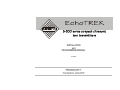
INSTALLATION and PROGRAMMING MANUAL 3rd edition Manufacturer: NIVELCO Process Control Co. H-1043 Budapest, Dugonics u. 11. Phone.: (36-1)-369-7575 Fax: (36-1)-369-8585 e-mail:[email protected] http://www.nivelco.com 1. 2. 3. 4. 5. 6. CONTENTS 3.1 3.2 3.3 4.1 4.2 4.3 4.4 5.1 5.2 INTRODUCTION............................................................................................................................................................................ 2 ORDER CODES ............................................................................................................................................................................ 3 TECHNICAL DATA ....................................................................................................................................................................... 4 Data of EchoTREK for liquids .......................................................................................................................................................................4 Data of EchoTREK for free flowing solids ....................................................................................................................................................7 Accessories ..................................................................................................................................................................................................7 INSTALLATION............................................................................................................................................................................. 8 Liquid Level Measurement............................................................................................................................................................................8 Open Channel Flow Measurement.............................................................................................................................................................10 Free Flowing Solids Level Measurement ...................................................................................................................................................10 Electrical Connection ..................................................................................................................................................................................11 PROGRAMMING ......................................................................................................................................................................... 12 5.2.1 5.2.2 5.2.3 5.2.4 5.2.5 5.2.6 Touch-Magnet Programming (only for level transmitters for liquids)..........................................................................................................13 Programming of the EchoTREK by the SAP-100 Programming Module ...................................................................................................16 The SAP-100 Programming Module..............................................................................................................................................................................17 Programming with the SAP-100 Programming Module ................................................................................................................................................18 Indications of the SAP-100 Programming Module and the LEDs .................................................................................................................................19 Current Output Scaling ..................................................................................................................................................................................................20 QUICKSET.....................................................................................................................................................................................................................21 Full Parameter Access...................................................................................................................................................................................................23 PARAMETERS – DESCRIPTIONS AND PROGRAMMING ....................................................................................................... 24 6.1 6.2 6.3 6.4 6.5 6.6 6.7 6.8 6.9 6.10 6.11 6.12 Measurement Configuration .......................................................................................................................................................................24 Current Output ............................................................................................................................................................................................31 Relay Output...............................................................................................................................................................................................32 Measurement Optimisation.........................................................................................................................................................................33 Volume Calculation.....................................................................................................................................................................................39 Volume Flow Measuring .............................................................................................................................................................................40 32-Point Linearisation Curve ......................................................................................................................................................................45 Informational Parameters ...........................................................................................................................................................................46 Additional Open Channel Flow Metering Features.....................................................................................................................................48 Test Parameters .........................................................................................................................................................................................48 Simulation Mode .........................................................................................................................................................................................49 Access Lock................................................................................................................................................................................................49 7. ERROR CODES .......................................................................................................................................................................... 50 SOUND VELOCITIES IN DIFFERENT GASES ................................................................................................................................... 51 1 EchoTREK Compact Ultrasonic Level Transmitters Thank you for choosing a NIVELCO instrument. We are sure that you will be satisfied throughout its use. 1. INTRODUCTION Application The EchoTREK compact ultrasonic level transmitters from NIVELCO are an excellent tool for the level measurement of liquids and free flowing solids. Level measurement technology based on the non-contacting ultrasonic principle is especially suited for applications where, for any reason, no physical contact can be established to the surface of the material to be measured. Such reasons may include corrosive attack by the process medium against the measuring device material (acids), possible contamination (sewage) or particles of the process medium adhering to the measuring device (adhesive materials). Principle of Operation The ultrasonic level metering technology is based on the principle of measuring the time required for the ultrasound pulses to make a round trip from the sensor to the level to be measured and back. The sensor emits an ultrasonic pulse train and receives the echoes reflected. The intelligent electronic device processes the received signal by selecting the echo reflected by the surface and calculates from the time of flight the distance between the sensor and the surface which constitutes the basis of all output signals of the EchoTREK EchoTREK Compact Ultrasonic Level Transmitters A Total beam angle of 5°-7° at –3 dB as is featured by most of Nivelco’s SenSonic transducers ensuring a reliable measurement in narrow silos with uneven side walls as well as in process tanks with various protruding objects. Furthermore, as a result of the narrow beam angle - the emitted ultrasonic signals have an outstanding focusing deep penetration through gases, vapour and foam is ensured. 5m r=22 cm 10 m r=44 cm 15 m r=66 cm 20 m r The Diameters corresponding to 5° beam angle. r=88 cm Dead Band is a feature common to all ultrasonic level meters. It is specified as “Minimum measuring distance” in the Technical Data Table. 2 2. ORDER CODES The order codes of the EchoTREK for liquids: EchoTREK S TYPE CODE Transmitter T Transmitter with B local indicator 3 TRANSDUCER / HOUSING CODE PP / Aluminium PVDF / Aluminium PTFE / Aluminium St. St. / Aluminium PP / Plastic PVDF / Plastic PTFE / Plastic St. St. / Plastic A B T S P V F M * For measuring ranges of PTFE (teflon) and St.St.(staninless steel) versions, see Technical Data table RANGE* CODE 2 25 m 15 m 4 10 m 6 8m 7 6m 8 4m 9 MOUNTING BSP thread NPT thread DN 80 DN 100 DN 125 DN 150 DN 200 200 mm bracket 500 mm bracket 700 mm bracket CODE 0 N 2 3 4 5 6 K L M CODE 85 to 265 VAC 4...20 mA+Relay 4...20 mA+HART+Relay RS485+Relay 4...20 mA+Relay (limited pr.) 10.5 to 40 VDC, 10.5 to 28 VAC 4...20 mA+Relay 4...20 mA+HART+Relay RS485+Relay 4...20 mA+Relay (limited pr.) 1 3 5 A 2 4 6 B Process connections: threaded with S_ _-39_ , 38_ and 37_ flange bracket or aiming kit with all other models Order code of the EchoTREK for free flowing solids: EchoTREK S 3 Under development 3 EchoTREK Compact Ultrasonic Level Transmitters 3. TECHNICAL DATA 3.1 Data of EchoTREK for liquids General data Product name Product description Transducer materials EchoTREK ST/SB-300 series Compact type ultrasonic level transmitter Polypropylene (PP) Kynar (PVDF) Teflon (PTFE) Stainless Steel (DIN 1.4571, AISI SS316Ti) Housing material Plastic: PBT fibre-glass reinforced, flame-retardant (DuPont) Aluminium: Powder paint coated PP, PTFE and PVDF versions: -30°C ... +90°C Stainless Steel versions : -30°… to +100°C (120° for max. 2 hours) Process temperature Ambient temperature -30°C ... +60°C with SAP-100 -25°C ... +60°C If necessary, protect the device from over-heating by direct sunshine! Pressure (Absolute.) Seals 0.3 ... 3 bar (0,03 ... 0,3MPa) Stainless steel versions 0,9 ... 1,1 bar (0,09 ... 0,11 MPa) PP transducer: EPDM All other transducer versions: FKM (Viton) Mechanical protection Sensor: IP68 (submersible) Housing: IP67 (NEMA 6) High voltage version: 85 ... 255 V AC / 6 VA Low voltage version: 10,5 ... 40 VDC / 3,6 W, 10,5 ... 28 V AC / 4 VA Power supply / Consumption Accuracy* Resolution Outputs Electrical connections Electrical protection ± (0.2% of the measured distance plus 0.05% of the range) < 2 m: 1 mm, 2...5 m: 2 mm, 5...10 m: 5 mm, > 10 m: 10 mm Analogue: 4/20 mA, 600 Ohm, galvanically isolated, secondary lightning protection Contact: SPDT (NO/NC); 250 V AC, 3 A Interface: RS485 (optional) HART (optional) Display (SAP-100): 6 digits, icons and bargraph, Custom LCD 2 x Pg16 and 2 x ½” NPT Wire cross section: 0,5 ... 2,5 mm2 Class I. * Under optimal circumstances of reflection and stabilised transducer temperature. EchoTREK Compact Ultrasonic Level Transmitters 4 Special data of EchoTREK for liquids with PP and PVDF transducers Type ST-39- ST-38- ST-37- SB-39- SB-38- SB-37- Transducer material Maximum measuring distance * [m / ft] Min. measuring distance* (Dead band) [m / ft] Total beam angle (-3 dB) Measuring frequency Process connection ST-36- SB-36- ST-34- SB-34- ST-32- SB-32- PP or PVDF PP or PVDF PP or PVDF PP or PVDF PP or PVDF PP or PVDF 4 / 13 6 / 20 8 / 26 10 / 33 15 / 49 25 / 82 0,2 / 0,65 0,25 / 0,82 0,35 / 1,2 0,35 / 1,2 0,45 / 1,5 0,6 / 2 6° 80 kHz 1 ½” thread 5° 80 kHz 2” thread 7° 50 kHz 2” thread 5° 60 kHz Flange 5° 40 kHz Flange 7° 20 kHz Flange STS-34- SBS-34- * (taken from the transducer face) Special data of EchoTREK for liquids with PTFE and Stainless Steel transducers Type STT-39- STT-38- STT-37- SBT-39- SBT-38- SBT-37- STS-36- SBS-36- Transducer material PTFE PTFE PTFE St. St. St. St. St. St. Maximum measuring distance * [m/ft] Min. measuring distance* (Dead band) [m/ft] Total beam angle (-3 dB) Measuring frequency Process connection 3 / 10 5 / 16 6 / 20 7 / 23 12 / 39 15 / 49 0,2 / 0,65 0,25 / 0,82 0,35 / 1,2 0,4 / 1,3 0,55 / 1,8 0,65 / 2,2 6° 80 kHz 1 ½” thread 5° 80 kHz 2” thread 7° 50 kHz 2” thread 60 kHz Flush flange 40 kHz Flush flange 7° 20 kHz Flush flange 5° STS-32- SBS-32- * (taken from the transducer face) SAP-100 Programming Module Field indication Ambient temperature Housing material 5 6 digits, icons and bargraph, Custom LCD -25°C … +60°C PBT fibre-glass reinforced plastic, flame-retardant (DuPont) EchoTREK Compact Ultrasonic Level Transmitters Dimensions of EchoTREK for liquids EchoTREK S-39- / PP, PVDF, PTFE ~56.5 EchoTREK S-37- / PP, PVDF, PTFE ~56.5 ~89 ~148 2 pcs Pg16 2 pcs Pg16 2 pcs Pg16 2x NPT1/2" 2x NPT1/2" 2x NPT1/2" BSP length 15 NPT length 22 ø122 DIN DN125 PN16 JIS 10K 125A ~143 ~56.5 2pcs Pg16 2xNPT1/2" ~105 19 2xNPT1/2" ANSI 5" 150 psi EchoTREK Compact Ultrasonic Level Transmitters ~89 2pcs Pg16 ~30 ø74 ~56.5 ~43 ~143 ~89 EchoTREK S-32- / PP, PVDF ~143 ~56.5 2xNPT1/2" DIN DN80 PN16 ANSI 3" 150 psi JIS 10K 80A EchoTREK S-34- / PP, PVDF 19 EchoTREK S-36- / PP, PVDF BSP length 15 NPT length 22 19 BSP length 15 NPT length 22 2pcs Pg16 BSP or or NPT 2" ~80 BSP or or NPT 2" ~60 ~60 BSP or or NPT 1 1/2" ~89 ~56.5 ~148 ~89 ~148 ~89 EchoTREK S-38- / PP, PVDF, PTFE DIN DN150 PN16 ANSI 6" 150 psi JIS 10K 150A ø148 6 ~89 DIN DN80 PN16 ANSI 3" 150 psi 3.2 2pcs Pg16 2xNPT1/2" ~89 2pcs Pg16 2xNPT1/2" DIN DN125 PN16 ANSI 5" 150 psi ~56.5 25 2xNPT1/2" ~56.5 25 20.5 2pcs Pg16 EchoTREK SS-32- / St. St. ~190 ~56.5 ~175 ~89 EchoTREK SS-34- / St. St. ~184 EchoTREK SS-36- / St. St. DIN DN150 PN16 ANSI 6" 150 psi Data of EchoTREK for free flowing solids General data Special data Dimensions (Under development) 3.3 Accessories - 7 2 x Pg16 cable gland Magnetic screwdriver (for Touch-Magnet Programming) Installation and Programming Manual EchoTREK Compact Ultrasonic Level Transmitters 4. INSTALLATION 4.1 Liquid Level Measurement POSITION The optimal position of the EchoTREK is between 1/2 radius and 2/3 diameter of the (cylindrical) tank / silo. (Take also sonic cone on page 1 into consideration.) PARALLELITY The sensor face has to be parallel to the surface of the liquid within ± 2-3°. EchoTREK Compact Ultrasonic Level Transmitters TEMPERATURE Make sure that the transmitter will be protected against overheating by direct sunshine. Sunshade 8 STAND-OFF PIPE The structure of the stand off pipe should be rigid, the inner rim where the ultrasonic beam leaves the pipe should be rounded. L L OBSTACLES Make sure that no in-flow path or objects (e.g. cooling pipes, ladders, bracing members, thermometers, etc) or no tank wall of the ragged surface protrude into the sensing cone of the ultrasonic beam. Although up to two fix objects in the tank / silo that disturb the measurement can be blocked out by the appropriate programming of the EchoTREK 150 200 250 300 350 ØD FOAM ØD L Foaming of the liquid surface may render ultrasonic level metering impossible. If possible, a location should be found, where foaming is the smallest (the device should be located as far as possible from liquid inflow) or a stilling pipe or well should be used. FUME/VAPOUR In case of closed tanks containing chemicals or other liquids creating fume/gases above the liquid surface especially for outdoor tanks exposed to the sun, a strong reduction of the nominal measuring range of the ultrasonic device is to be considered during device selection. Devices with lower measuring frequency (40, 20 kHz) are recommended depending on the range. 9 Dmin S_ _ -38_ 60 60 65 75 85 S_ _ -37_ 60 75 90 105 120 Dmin S_ _ -36_ S_ _ -34_ 90 80 * 200 80 * 350 85 * 500 90 * * For values consult your distributor Models of S-32 with plastic transducer must not be installed in stand-off pipes since its transducer face has to protrude into the tank. L WIND An intensive moving of the air (gas) in the vicinity of the ultrasonic cone is to be avoided. A strong draft of wind may "blow away" the ultrasound. Devices with lower measuring frequency (40, 20 kHz) are recommended. S_ _ -39_ 50 50 65 80 95 ØD 320 440 800 S_ S -36_ 80 - Dmin S_ S -34_ 125 - S_ S -32_ 150 EchoTREK Compact Ultrasonic Level Transmitters 4.2 Open Channel Flow Measurement • • • • For ultimate accuracy, install the sensor as close as possible above the expected maximum water level (see minimum measuring range). Install the device upstream in a place defined by the characteristics of overflow and metering channel along the longitudinal axis of the flume or weir. In case of Parshall flumes supplied by NIVELCO the location of the sensor is marked. From the point of view of measurement accuracy the length of the channel sections preceding and following the measuring flume and their method of joining to the measuring channel section are of critical importance. Despite of the most careful installation, the accuracy of flow metering will be lower than that of specified for distance measurement. It will be determined by the features of the flume or weir applied. 4.3 Free Flowing Solids Level Measurement POSITION The optimal position of the EchoTREK is between 1/2 radius and 2/3 diameter of the (cylindrical) tank / silo. (Take also sonic cone on page 1 into consideration.) MATERIAL INFLOW Install the device as far away from the filling point(s) as possible. PNEUMATIC FILLING Mount the sensor at a place where the speed of the filledin material reaches its lowest value. Recommended area of mounting (top view of silo) AIMING To avoid problems caused by surface unevenness, in most cases aiming (tilting) of the device is required, which can easily be carried out with the SAA-102 Aiming Device of NIVELCO. Aiming is best carried out, when the tank/silo is almost empty. In most cases, the sensor should be aimed towards the silo outlet. On applications where repose is not present or typically in tall and narrow silos (diameter : height = 1 : 5 or narrower, e.g. ∅3x18 m) aiming is not critical: the sensor should face straight downwards. EchoTREK Compact Ultrasonic Level Transmitters 10 4.4 Electrical Connection 11 • Screw out the hexagonal countersunk screw at the side of the model. Lift the tilt cover to access the screw terminal. • There is a basic requirement for separating the 4...20 mA signal cable and 230 V AC supply (or output relay) cable by shielding. • For grounding the unit, either use the grounding screw terminal on the outside of the housing; or use a three wire mains cable, connecting the third wire to the internal grounding screw terminal. • Three-wire installation is also possible for the 24 V DC versions by connecting the terminals 1 and 6. In this case the galvanic isolation is not provided. • The unit may be damaged by electrostatic discharge (EDS), via terminal, thus apply the precautions commonly used to avoid electrostatic discharge. EchoTREK Compact Ultrasonic Level Transmitters 5. PROGRAMMING The EchoTREK will be delivered with the following Factory Default: ⇒ Current output, display and bargraph: LEVEL ⇒ 4 mA: assigned to the minimum level 0% ⇒ 20 mA: assigned to the maximum level 100% ⇒ Error indication by the current output: hold last value ⇒ Damping: 60 sec for liquids, 300 sec for solids The device can be programmed in two ways: • Touch-Magnet Programming by the supplied magnetic screwdriver (with level transmitters for liquids only), see 5.1. Assignment of the levels to the 4 and 20 mA current output, relay switch differential (both with an accuracy of ± 20 mm) error indication by the analogue signal and damping can be set. • With the SAP-100 programming module, see 5.2. All features of the device can be set, such as measurement configuration and optimization, relay programming, 32-point linearisation, dimensions for 6 tanks with different shape and for 21 different open channels (flume or weir) etc. Devices with the type number EchoTREK SB... are already equipped with the SAP-100. The EchoTREK is fully operational without the SAP-100. The SAP-100 is only needed for programming and/or displaying measurement values. If the transmitter is left in Programming Mode by mistake, it will automatically return to Measurement Mode after 30 minutes and will operate with the parameters entered during the last completed programming. EchoTREK Compact Ultrasonic Level Transmitters 12 5.1 Touch-Magnet Programming (only for level transmitters for liquids) The following can be programmed: with the supplied magnetic screwdriver: • Assignment of the 4 mA analogue output to a required e.g. min. level / max. distance • Assignment of the 20 mA analogue output to a required e.g. max. level / min. distance • Error indication by the current output (Hold, 3.6 mA, 22 mA) see Chapter 6.2.(P12) • Relay switching different • Damping (10, 30 and 60 sec) • Reset to the factory default Note: Current output can also be assigned in inverted mode: 4 mA= 100% (Full), 20 mA= 0% (Empty) Programming is only possible if the EchoTREK receives valid echo i.e.“ECHO” LED is lit ! and transmitter is in LEV measuring mode (factory default). The accuracy of the setting with this programming method is limited to ± 20 mm. Thus the relay switching difference between “On” and “OFF” must be greater than 20 mm. magnet Place magnet to at 0% level: LED O O O Hold magnet in place while setting: LED O O O Remove magnet when ready: LED O O O Place magnet to at 100% level: LED O O O Hold magnet in place while setting: LED O O O Remove magnet when ready: LED O O O LEDs For programming: put magnetic screwdriver in accordance with the drawing to place A or B and check the LEDs for their status: = LED is on, = LED is blinking, = LED is off, = LEDs are blinking alternatively Make sure that after programming completed all other magnetic influences will be avoided. Minimum level, 0%, empty tank (assignment to 4 mA,) Place the EchoTREK at a distance to the target corresponding to the required maximum distance/minimum level. Action LED indication 1) Check valid echo = Valid echo received, transmitter programmable 2) Place magnet to the symbol “A” and = Transmitter in programming mode 3) Hold magnet in place = Distance assigned to 4 mA 4) Remove magnet when all LEDs are off = Programming completed 13 Use level in tank or a fix target e.g. the wall EchoTREK Compact Ultrasonic Level Transmitters Maximum level 100%, full tank (assignment to 20 mA) Place the EchoTREK in a distance to the target corresponding to the required minimum distance/ maximum level. Action LED indication 1) Check valid echo = Valid echo received, transmitter programmable 2) Place magnet to the symbol “B” and = Transmitter in programming mode 3) Hold magnet in place = Distance assigned to 20 mA 4) Remove magnet when all LEDs are off = Programming completed Use level in tank or a fix target e.g. the wall Programming relay switch-on point (the level where relay becomes energised) Place the EchoTREK at a distance to the target corresponding to the required switch-on point. (Do not forget to check valid Echo!) Action LED indication 1) Place magnet to symbol “A”” =Programming mode 2) Place magnet to symbol “B” and =Programming in progress 3) Hold magnet to symbol “B” =Programming in Progress 4) Place magnet to symbol “A” =Programming in Progress 5) Remove magnet when all LEDs are off =End of Programming Use level in tank or a fix target, i.e. the wall Programming relay switch-off point (the level where relay becomes de-energised) Place the EchoTREK at a distance to the target corresponding to the required switch-off point. (Do not forget to check valid Echo!) Action LED indication 1) Place magnet to symbol “A” =Programming mode 2) Place magnet to symbol “B” and =Programming in progress 3) Hold magnet to symbol “B” =Programming in progress 4) Keep holding magnet to symbol “B” =Programming in progress 5) Remove magnet when all LEDs are off =End of Programming Please note that the smallest switch-differential achievable with magnet programming is 20 mm. EchoTREK Compact Ultrasonic Level Transmitters Use level in tank or a fix target, i.e. the wall 14 “Error indication” by the current output (Check valid echo as above) Action LED indication 1) Place magnet to the symbol “A” = Transmitter in programming mode 2) Place magnet to the symbol “B” repeatedly to select the required error indication mode = Hold last value = 3.6 mA = 22 mA 3) Place magnet to the symbol “A” = Programming completed “Damping” (Check valid echo as above) Action LED indication 1) Place magnet to the symbol “B” = Transmitter in programming mode 2) Place magnet to the symbol “A” repeatedly to select the required damping = 10 sec = 30 sec = 60 sec 3) Place magnet to the symbol “B” = Programming completed Reset (to factory default) Action LED indication 1) Place magnet to the symbol “B” = Programming mode 2) Place magnet to the symbol “A and = Reset in progress 3) Hold magnet to the symbol “A” = Reset in progress 4) Remove magnet when all LEDs are off = End of programming Error indications during programming (by LEDs) Action LED status = error indicated Correction 1) Attempted programming = blinking twice = No Echo Find valid echo 2) Attempted programming = blinking three times = access denied (access code active) With use of SAP-100 see Chapter 5.2 (P99) 3) Attempted programming = blinking four times = EchoTREK not in LEV meas. mode With use of SAP-100 see Chapter 5.2 (P01) 4) Programming of the relay =blinking alternately = switch-differential too small Set switch-differential greater than 20 mm 15 EchoTREK Compact Ultrasonic Level Transmitters 5.2 Programming of the EchoTREK by the SAP-100 Programming Module The SAP-100 supports 3 separately accessible programming modes representing 3-layers of programming complexity, depending on user choice. PLUG-IN PROGRAMMER Current Output Scaling QUICKSET Full Parameter Access Current Output Scaling (5.2.4) Recommended as a simple and fast way to modify the scaling of the current output. QUICKSET (5.2.5) Recommended as a simple and fast way to set up the EchoTREK by 8 basic parameters This menu driven programming mode supports the following basic settings: • Engineering unit for the display (Metric or US) • Maximum measuring distance • Assignment of min level to 4mA • Assignment of max level to 20mA • Error indication by the current output • Damping time • Assignment of level to energising of the relay • Assignment of level to de-energising of the relay Full Parameter Access (5.2.6) All features of the EchoTREK can be accessed by parameter addresses: Example: • Measurement configuration • Outputs • Measurement optimalisation • 6 pre-programmed tank shapes for volume calculation • 32-point linearisation table • Open channel flow metering functions EchoTREK Compact Ultrasonic Level Transmitters 16 5.2.1 The SAP-100 Programming Module The plug in programming and display module is used for programming but also for display even in case of Touch-Magnetic Programming The Display and keys ENTER NEXT UP DOWN Symbols used on the LCD: • • • • • • • • • • • DIST – Distance (measuring) mode LEV – Level (measuring) mode VOL – Volume (measuring) mode FLOW – Open channel (flow metering) mode PROG - Programming mode (device under programming) RELAY – Relay T1 - TOT1 volume flow totaliser (resetable aggregate) T2 - TOT2 volume flow totaliser (aggregate) FAIL - Measurement / device error ⇑⇓- Level changing direction Bargraph assigned to the current output or echo strength Symbols used on the frame: • • 17 M – Metric system US – US calculation system EchoTREK Compact Ultrasonic Level Transmitters 5.2.2 Programming with the SAP-100 Programming Module Programming will be performed by pressing one or two keys (simultaneously). Single key pressing E Press key ENTER - to save parameter address and go to parameter value to return from parameter value to parameter address Press NEXT to move the blinking of the digit to the left Press UP to increase value of the blinking digit Press DOWN to decrease value of the blinking digit Double key pressing (Short overview, for details see in 5.2.4, 5.2.5 and 5.2.6) Press the two keys simultaneously for desired programming step. t all cel Can s ** tio n ifica d o m Return to default* * LOAD will be displayed ** CANCEL will be displayed E s ti on * ifica ddress d o all m eter a m cel Can to par a n r u re t Display default value * cancellation immediately active Notes: If the parameter value is not accessible i.e. the parameter address keeps blinking after pressing ENTER E , • the parameter is either a read-out type, or • the secret code prevents the modification (see P99). If the modification of the parameter value is not accepted i.e. the parameter value keeps blinking after pressing ENTER • the modified value is either out of the range, or • the code entered is not valid for this parameter EchoTREK Compact Ultrasonic Level Transmitters Actual Qui ckse E Basic steps while parameter value is blinking Parameter value Current output scaling Default Full Parameter Access E Basic steps while parameter address is blinking Parameter value Enter into or quit programming modes E , 18 5.2.3 Indications of the SAP-100 Programming Module and the LEDs ENTER UP NEXT DOWN COM Field indication RELAY LED indication Depending on the measuring mode (see P01 in Chapter 5.2.3) the following values can be displayed (relevant symbol is lit): • • • • • • ECHO Distance Level Volume Flow TOT1 and TOT2 Error code (if “FAIL” is blinking) RELAY - LED LED is lit when relay is energized To scroll through the displays above press NEXT To display transducer temperature, press UP ECHO - LED LED is lit as long as the device receives a valid echo signal repeatedly. COM - LED LED is lit during communication (Remote control) : (°C/°F) To display current output value, press DOWN : (mA) 19 EchoTREK Compact Ultrasonic Level Transmitters 5.2.4 Current Output Scaling This programming mode is the simple and fast way to modify the scaling of the current output. For changing all parameters other than those assigned to 4 and 20 mA use either the QUICKSET (5.2.2). or the Full Parameter Access (5.2.3). Current Output Scaling mode is useful for re-scaling i.e. for modifying of the minimum and maximum level assigned to the output signals 4 and 20 mA, if other than the factory default. Current Output Scaling is aided by 2 screens for setting. The instructions for this programming can also be found below the screw cover on the front panel of the EchoTREK. Note: For this programming the EchoTREK has to be in level measurement mode. See chapter 6.1 (P01). Keys ENTER UP E (press for 3 seconds) + UP / DOWN Increase/decrease blinking digit or scroll up/down Move left with the blinking digit NEXT UP Function Enter or exit Current Output Scaling programming mode + DOWN ENTER "GET LEVEL" - display actual level value measured by the EchoTREK Save actual value on the screen and move to the next screen E NEXT + UP Quit Current Output Scaling without saving the modifications NEXT + DOWN Display Factory Default of the relevant screen Screens 4:xxxx 4 represents the output signal x = level value to be assigned 20:xxxx 20 represents the output signal x = level value to be assigned Actions 4 mA xxxx:– level value assigned to 4 mA current output Manual: set required value (by UP / DOWN / NEXT keys) and save it (by the key ENTER E ) Automatic: use the “GET LEVEL” function (UP + DOWN ) to obtain actual measured value with level in tank or a fix target, e.g. wall. (“GET LEVEL” functions only if ECHO LED is lit) and save it as above. DEFAULT: 0 m (0%, Empty tank) 20 mA xxxx: – Level value assigned to 20 mA current output Manual: set required value (by UP / DOWN / NEXT keys) and save it (by the key ENTER E ) Automatic: use the “GET LEVEL” function (UP + DOWN ) to obtain actual measured value with level in tank or a fix target, e.g. wall. (“GET LEVEL” functions only if ECHO LED is lit) and save it as above. DEFAULT: max. level = max. measuring distance - dead band (100%, Full tank) See chapter 5.1 (P04, P05) EchoTREK Compact Ultrasonic Level Transmitters 20 5.2.5 QUICKSET Recommended as a simple and fast way to start up EchoTREK. QUICKSET programming is aided by 8 screens to set the 8 basic parameters of the device if the required application is uncomplicated level metering, recommended for liquids only. The instructions of this programming mode are also to be found, below the screw cover, on the front panel of the EchoTREK. The DEFAULT of the Current output, Display and Bargraph is LEVEL. This can be modified only in the Full Parameter Access mode see 5.1 (P01). Keys Function ENTER E + DOWN (press for 3 seconds) Enter or exit QUICKSET programming mode UP Increase/decrease blinking digit or scroll up/down / DOWN NEXT UP Move left with the blinking digit + DOWN ENTER E "GET LEVEL" - display actual level measured by EchoTREK Save value on the screen and move to the next screen NEXT + UP Quit QUICKSET programming mode without saving the modifications NEXT + DOWN Display Factory Default of the relevant screen See next page for details. 21 EchoTREK Compact Ultrasonic Level Transmitters Screens AP:xxyy Actions APplication xx= select “EU” (European) for metric or “US” for US engineering units (Use UP / DOWN yy= indicating “Li” for liquids or “So” for solids level measurement (can not be changed). keys) DEFAULT: EU H:xxxx 4:xxxx 20:xxxx Er:xxxx dt: xxxx rE:xxxx rd : xxxx H = xxxx maximum measuring distance – Distance between transducer face and tank/silo bottom Manual: set value (Use UP / DOWN / NEXT keys) and save it (by ENTER E ) + DOWN ) to obtain actual measured value with level in tank or a fix Automatic: use the “GET LEVEL” function (UP target, i.e. wall. (“GET LEVEL” functions only if ECHO LED is lit) and save it as above. DEFAULT: maximum measuring distance [m], see Technical Data Table 4 mA xxxx – level value assigned to 4 mA current output Manual: set level value (by UP / DOWN / NEXT keys) and save it (by ENTER E ) + DOWN ) to display the actual measured value with level in tank or a fix Automatic: use the “GET LEVEL” function (UP target, i.e. wall. (“GET LEVEL” functions only if ECHO LED is lit) and save it as above. DEFAULT: 0 m (0%, Empty tank) 20 mA xxxx – level value assigned to 20 mA current output / DOWN / NEXT keys) and save it (by ENTER E ) Manual: set level value (Use UP Automatic: use the “GET LEVEL” function (UP + DOWN ) to obtain actual measured value with level in tank or a fix target, i.e. wall. (“GET LEVEL” functions only if ECHO LED is lit) and save it as above. DEFAULT: max. level = max. measuring distance – dead band [m] (100%, Full tank) (See Technical Data Table) Error indication by the current output – select “Hold”, “3.6” mA or “22” mA (by UP / DOWN key) and save it as above. DEFAULT: hold last value damping time: select required damping time (by UP DEFAULT: 60 sec for liquids, 300 sec for solids / DOWN key) and save it as above. relay Energised xxxx: level of the relay energised state If the value exceeds this programmed value the relay will be energised relay de-energised xxxx: level of the relay de-energised state If the value sinks below this programmed value the relay will be deenergised Note: Current output can also be programmed for inverted operation: 4 mA= 100% (Full), 20 mA= 0% (Empty) EchoTREK Compact Ultrasonic Level Transmitters 22 5.2.6 Full Parameter Access To access all features provided by the EchoTREK. Description of all parameters can be found under the chapter “Parameter” (Chapter 6.). Keys ENTER E + NEXT (press for 3 seconds) Function Enter or exit Full Parameter Access programming mode. In this programming mode, the display will indicate: yy:xxxx yy is the Parameter Address xxxx is the Parameter Value Note: Measuring is going on during programming in accordance with the old parameter set. New parameter set will be valid after returning to measurement from programming mode. Steps and indications of the Full Parameter Access programming mode pressing Keys while Parameter Address is blinking while Parameter Value is blinking ENTER E Go to the Parameter Value Save the modification of the Parameter Value and return to the Parameter Address NEXT + UP Cancel all modifications of the actual programming phase. Pressing for 3 secs is required while CANCEL will be displayed for warning Neglect the modification of the Parameter Value. and return to the Parameter Address without saving the modifications NEXT + DOWN Reset entire device to Factory Default. Since this action will reset all parameters, “LOAD” will appear on the display: - to confirm, press ENTER - to escape, press any other key - Exception: clearing TOT 1 (See at P77) Display default of the Parameter Values 23 E ) Move blinking of the digit to the left NEXT UP (it can be saved by pressing ENTER / DOWN Modify the blinking digit (increase, decrease) or scroll up/down EchoTREK Compact Ultrasonic Level Transmitters 6. PARAMETERS – DESCRIPTIONS AND PROGRAMMING 6.1 Measurement Configuration P00: - cba Application/Engineering Units Programming of this parameter will result in loading the factory default with the corresponding engineering units. a 0 1 Operating (measurement) mode Liquid level measurement Free flowing solids level measurement b 0 1 Engineering units (according to “c”) ft Metric m inch cm inch c 0 1 Calculation system Metric US Display indication “Li” “So” Attention: mind the sequence! Coming to this parameter the right value “a” will be blinking first. FACTORY DEFAULT: 000 EchoTREK Compact Ultrasonic Level Transmitters 24 P01: - ba Measurement Mode Display, current output and the switching points of the relays will be interpreted in the engineering units of the (measured or calculated) process value corresponding to the programmed measurement mode. On the other hand the higher the “a” of the programmed parameter value the more (measured or calculated) process values can be displayed on the screen. (e.g. if P01=b0 only the Distance, if P01=b5 the Distance the Level, the Volume and the Flow can be displayed. Exception if P01=b2 or b4.) a 0 1 2 3 4 5 Measurement Mode Distance Level Level in percentage Volume Volume in percentage Flow b 0 1 Bargraph indication Echo strength Current output Display symbol DIST LEV LEV% VOL VOL% FLOW Attention: mind the sequence! Coming to this parameter the right value “a” will be blinking first. FACTORY DEFAULT: 11 P02: - cba Calculation units a 0 1 Temperature °C °F Attention: mind the sequence! Coming to this parameter the right value “a” will be blinking first. This table is interpreted according to P00(c), P01(a) and P02(c) and is irrelevant in case of percentage measurement ( P01(a)= 2 or 4 ) b Volume Weight (set also P32) Volume flow Metric US Metric US Metric US 0 m3 ft3 lb (pound) m3/time ft3/time 1 liter gallons tons tons liter/time gallons/time c 0 1 2 3 25 Time Sec Min Hour Day FACTORY DEFAULT: 000 EchoTREK Compact Ultrasonic Level Transmitters P03: - - - a Values Displayed-Rounding It is important to keep in mind that the instrument is measuring distance as basic quantity. Measured distance Xmin – 2m 2m – 5m 5m – 10m over 10m Resolution 1mm 2mm 5mm 10mm The resolution depending on the distance can be considered as a kind of rounding that will be contained in all further value (of level, volume or volume flow) calculated. Therefore if programmed for DIST or LEV measurement the setting of P03 is irrelevant. Displayed form x.xxx xx.xx xxxx. xxxxx. xxxxxx. x.xxxx : e (exponential form) (overflow) Err4 Obviously the decimal position will be shifted with increasing value displayed. (See table at the left). Values over one million will be displayed in exponential format whereas the value (e) represents the exponent. Over the value of 1x10¹⁰ Err4 (overflow) will be displayed. Displayed VOL or FLOW Displayed value 0.000 – 9.999 10.000 – 99.999 100.000 – 999.999 1000.000 – 9999.999 100000.000 – 99999.999 1 million – 9.99999*109 over 1*1010 Rounding Parameter value “a” 0 1 2 3 4 5 Steps in the displayed value 1 no rounding 2 5 10 20 50 A couple of millimetres of fluctuation of the basic DIST value (e.g. due to waves) will be enlarged by the mathematical operations. This enlarged fluctuation in displaying VOL or FLOW can (if disturbing) be avoided by rounding to be set in P03. Rounding value 2, 5, 10 etc represents the steps by which the calculated value will be changed in its (one or two) last digit(s). Examples: P03=1 steps by 2: 1,000; 1,002; 1,004 P03=5 steps by 50: 1,000; 1,050; 1,100 or 10,00; 10,05(0); 10,10(0); 10,15(0) (the 0 from the steps 50, 100, 150 etc will not be displayed) FACTORY DEFAULT: 0 EchoTREK Compact Ultrasonic Level Transmitters 26 DEFAULT value of P05 Min. meas distance (dead band) programmed value of P04 Max measuring dist of the application Max. measurement range of the device DEFAULT value of P04 Max. measuring distance of the device Close end blocking (programmed value of P05 DEFAULT value of P05)) DIST=distance (measured) Programmed measurement range of the application LEV=level (calculed; P04-DIST) VOL=volume (calculated from DIST LEV) P06 Far end blocking Basic conception and elements of the ultrasonic measurement 27 EchoTREK Compact Ultrasonic Level Transmitters P04: Maximum measuring distance The maximum measuring distance is the only one parameter that has to be programmed for each application other than distance measurement mode. The DEFAULT value of P04 (see table below) can also be displayed by double key pressing NEXT + DOWN . EchoTREK Level transmitters for liquids S-39 S-38 S-37 S-36 S-34 S-32 PP or PVDF (m/ft) 4 / 13 6 / 20 8 / 26 10 / 33 15 / 49 25 / 82 Maximum measuring distance PTFE Stainless Steel (m/ft) (m/ft) 3 / 10 5 / 16 6 / 20 7 / 23 12 / 39 15 / 49 Keep in mind that LEVEL (as the result of the measurement) = P04 (programmed) – DISTANCE (measured by the device) Since the accuracy of level (and all further calculated) value depends on the accuracy of the max measuring distance of the application which is the distance between the sensor face and the tank / silo bottom. To obtain the best accuracy for a liquid level measurement, measure this distance in the empty tank with the EchoTREK by using the “GET LEVEL” function (press UP and DOWN keys simultaneously) provided the bottom is flat. Enter the actual measured value displayed as P04. Values of the maximum measuring distance will be in accordance with the table below. Engineering unit m cm ft inch EchoTREK Compact Ultrasonic Level Transmitters Display format x.xxx or xx.xx xxx.x xx.xx or xxx.x xxx.x 28 P05: Minimum measuring distance (Close-end blocking) The EchoTREK will not accept any echo within the blocking distance set here. Automatic Close-end-blocking (Automatic Dead Band control) By using the factory default value, the unit will automatically set the smallest possible close-end-blocking distance i.e. the dead band. Manual close-end-blocking Manual close-end-blocking would be used for example to block out the echo originating from the bottom rim of a stand-off pipe or from any object protruding into the ultrasonic cone near to the transmitter. By entering a value, higher than the factory default, the minimum measuring range will be extended and fixed to the specified value. To display factory default of the minimum measuring distance press NEXT EchoTREK Level transmitters for liquids S-39 S-38 S-37 S-36 S-34 S-32 + DOWN . Factory default of the minimum measuring distance (dead band) with PP or PVDF with PTFE transducers with stainless Steel transducers (m/ft) trends (m/ft) (m/ft) 0,2 / 0,65 0,2 / 0,65 0,25 / 0,82 0,25 / 0,82 0,35 / 1,2 0,35 / 1,2 0,35 / 1,2 0,4 / 1,3 0,45 / 1,5 0,55 / 1,8 0,6 / 2 0,65 / 2,2 FACTORY DEFAULT: automatic dead band control 29 EchoTREK Compact Ultrasonic Level Transmitters 4 mA A). Level measurement Far end blocking is used to neglect incorrect level/volume readings and output actions below a preset level. In the far-end of the measuring range, for example tanks with heaters or other interfering objects (sludge, cone of silo etc.) may cause faulty readings. If the level of the medium sinks below the blocked out range: - ”Sub 0” will be indicated for the level and volume - Distance value is not interpretable - Current output will hold value corresponding to the far end blocking level 20 mA Far-end blocking mA P06: Level Volume "SUB 0" indication below this level P06 Far end blocking If the medium level is above the blocked out range: The calculation of level and volume will be based on the programmed tank dimensions, therefore the measured or calculated process values will not be influenced in any way, by the far end blocking value. B). Open channel flow metering Far end blocking will be used to neglect incorrect volume flow readings and output actions below a pre-set level, where accurate volume flow calculation is not possible any more. If the liquid level in the flume/weir falls below the blocked out range: The EchoTREK will act as follows: - Indicate ”No Flow” on the Display - Hold last valid data on the current output. If the level in the flume/weir is above the blocked out range: The calculation of volume flow will be based on the programmed flume/weir data, therefore the measurement values will not be influenced in any way, by the far end blocking value. FACTORY DEFAULT: 0 EchoTREK Compact Ultrasonic Level Transmitters 30 6.2 Current Output P10: Value (of distance, level, volume or flow) assigned to 4 mA current output P11: Value (of distance, level, volume or flow) assigned to 20 mA current output Values are interpreted according to P01(a). Please note that in case of programming for (LEV or VOL) % measurement the min and max value has to be entered in the relevant engineering units of LEV (m, ft) or VOL (m3, ft3). Assignment can be made so that the proportion between the change of the (measured or calculated) process value and the change of the current output be either direct or inverse. E.g. lev 1m assigned to 4mA and lev 10m assigned to 20mA represents direct proportion and lev 1m assigned to 20mA and lev 10 m assigned to 4mA represents the inverse proportion. FACTORY DEFAULT: P10 0 level (max distance) P11 max level (min distance) P12: - - - a Error indication by the current output In case of error the EchoTREK will provide one of the current outputs below. (For errors and their indications see Chapter 7). a 0 1 2 Error indication (according to NAMUR) Hold last value 3.6 mA 22 mA FACTORY DEFAULT: 0 31 EchoTREK Compact Ultrasonic Level Transmitters 6.3 Relay Output P13: - - - a a 0 1 2 3 Relay function Relay function DIFFERENTIAL LEVEL CONTROL (Hysteresis control) Relay is energised if the measured or calculated value exceeds the value set in P14 Relay is de-energised if the measured or calculated value descends under the value set in P15 Relay is energised in case of Echo Loss Relay is de-energised in case of Echo Loss COUNTER Used for open channel flow metering. A 140 msec pulse is generated every 1, 10, 100, 1.000 or 10.000 m3 according to P16. Level P14 P15 Time Relay Energised: De-energised: Also set: P14, P15 There is a need to set (in level min 20mm) hysteresis between P14 and P15 P16= 0: 1m3 P16= 1: 10 m3 P16= 2: 100 m3 P16= 3: 1.000 m3 P16= 4: 10.000 m3 FACTORY DEFAULT: 2 P14: … Relay parameter – Setpoint value FACTORY DEFAULT: 0 P15: … Relay parameter – Setpoint value FACTORY DEFAULT: 0 P16: … Relay parameter – Pulse rate FACTORY DEFAULT: 0 EchoTREK Compact Ultrasonic Level Transmitters 32 6.4 Measurement Optimisation P20: - - - a Damping Use this parameter to reduce unwanted fluctuation of the display and output. a 0 1 2 3 4 5 6 7 8 9 Damping time (seconds) None/moderate fume or waves no filter 3 6 10 30 60 100 300 600 1000 applicable recommended recommended recommended recommended applicable applicable not applicable not applicable LIQUIDS FREE FLOWING SOLIDS Heavy/dense fume or Granules Powders turbulent waves >2-3 mm < 2-3 mm Recommended for testing only not recommended not applicable not applicable applicable not applicable not applicable recommended not applicable not applicable recommended not applicable not applicable recommended applicable applicable applicable recommended recommended applicable recommended recommended not applicable recommended recommended not applicable applicable applicable FACTORY DEFAULT: for Liquids: 60 sec, for Solids: 300 sec P22: - - - a Dome top tank compensation To reduce disturbing effect of possible multiple echos. a 0 Compensation OFF 1 ON Applied In case the EchoTREK is mounted not in the centre of the top and the top is flat. In case the EchoTREK is mounted in the centre of a tank with dome-shaped top FACTORY DEFAULT: 0 33 EchoTREK Compact Ultrasonic Level Transmitters P23: - - - a Angle of repose (repose formation) only for free flowing solids applications This parameter provides information for the QUEST+ software for optimising the echo-search pattern. a 0 1 2 Estimated angle of repose No angle of repose (default) Below 15° (α) Over 15° (α) The optimal setting of this parameter can be done with the help of checking the echo strength in the read out parameter P72 indicating the echo amplitude in dB. The ideal setting of P23 is at which the parameter value in P72 becomes the best (nearest “0”). 1). Set P23 for a= 1, confirm it with [E] and switch to Measurement Mode then return to Programming Mode. 2). Observe the change of echo amplitude in P72 and record an average value. 3). Perform the above with the P23 = 2 setting. 4). Finally set P23 with the value of (a) at which the amplitude value in P72 is nearest to 0. FACTORY DEFAULT: 0 P24: - - - a Target tracking speed a 0 1 2 Tracking speed Standard Fast Special Remark For most applications For fast changing level Only for special applications (measuring range is reduced to 50% of the nominal value) The measuring window is inactive and the EchoTREK will respond practically instantly to any target. Recommended to fast target tracking, but usually not applicable for level metering. FACTORY DEFAULT: 0 EchoTREK Compact Ultrasonic Level Transmitters 34 P25: - - - a Selection of Echo within the measuring window A so-called measuring window is formed around the echo signal. The position of this measuring window determines the flight time for calculation of the distance of the target. (the picture below can be seen on the test oscilloscope) Received signal amplitude Echo 1. Echo 2. t "t" ultrasound flight time Some applications involve multiple (target + disturbing) echoes even within the measuring window. Basic echo selection will be done by the Quest + software automatically. This parameter only influences the echo selection within the measuring window. a 0 1 Echo in the window to be selected With the highest amplitude First one 2 Largest one Remark For most applications (both with liquids and solids) For liquids applications with multiple echoes within the Measuring Window Recommended for certain free flowing solids applications FACTORY DEFAULT: 0 P26: (m/h) Level elevation rate (filling speed) P27: (m/h) Level descent rate (emptying speed) Very heavy fuming Use these parameters to provide additional protection against echo loss in applications involving dust during the filling process (powders, dusting granules) or in case of very heavy fuming. These parameters must not be smaller than the fastest possible filling/emptying rate of the actual technology. For all other applications, use the factory default setting. FACTORY DEFAULT: 35 for Liquids (P00: Li) P27=2000 Very heavy fuming for Solids (P00: So) P27=500 EchoTREK Compact Ultrasonic Level Transmitters P28 - - - a Echo-loss handling a Echo-loss error indication Remark 0 Delayed 1 None 2 Advance to full During echo-loss in case of filling, the reading on the display and analogue output will shift towards the "full" tank/silo state with a level elevation rate (filling speed) preset in P26 3 Immediate In case of echo-loss, the display will immediately change to “no Echo” and the outputs will change according to the "Error Indication Mode" preset in P12. 4 No echo-loss indication in case of empty tank/silo During echo-loss, display and analogue output will hold last value. If the echo-loss prevails for 10 sec plus the time period set in P20 (damping time), the reading on the display will change to "no Echo" and the outputs will change according to the "Error Indication Mode" preset in P12. For the time of echo-loss, display and analogue output will hold last value. Echo-loss may occur in completely empty tanks with a spherical bottom due to deflection of the ultrasonic beam, or in case of silos with an open outlet. If the echo is lost when the tank/silo is completely empty, the indication will correspond to empty tank, in all other cases echo-loss indication will function according to the “Delayed”. FACTORY DEFAULT: 0 P29 Blocking out of object #1 P30 Blocking out of object #2 Up to two fix objects in the tank/silo that disturb the measurement can be blocked out. Enter the distance of the object from the transducer. Use the Echo Map (P70) to read out the precise distance of disturbing objects. FACTORY DEFAULT: 0 EchoTREK Compact Ultrasonic Level Transmitters 36 P31: Sound velocity at 20°C (m/sec or ft/sec depending on P00(c) ) Use this parameter if the sound velocity in the gases above the measured surface differs largely from that of in air. Recommended for applications where the gas is more or less homogeneous. If it is not, the accuracy of the measurement can be improved using the 32-point linearisation (P48, P49). For sound velocities in various gases see section “Sound Velocities”. FACTORY DEFAULT: P32: Metric (P00: “EU”): 343.8 m/s, US (P00: “US”): 1128 ft/s Specific gravity If you enter value (other than “0”) of specific gravity in this parameter, the weight will be displayed instead of VOL. FACTORY DEFAULT: 0 [kg/dm3] or [lb/ft3] depending on P00(c) P33: (m) Manual echo selection by moving the Measuring Window A so-called measuring window is formed around the echo signal (See scheme on the next page.) The distance of the target will be calculated from the flight time in accordance with the position of the measuring window. Use this parameter if the EchoTREK unambiguously selects a wrong echo; for example the echo reflected from the surface is much weaker than the interfering one(s) (see figure beside and on next page). Enter the distance of the correct echo and the software will move the measuring window and calibrate itself to the echo found there. To determine the distance of the correct echo, either use the Echo Map (to load-in a value from the Echo Map, see parameter P70), or measure the distance with an appropriate device, and enter this value in P33. 1. 2. If this parameter has been used (P33 is not 0), its value will be continuously updated with the valid echo position. This means, that in case of a power loss, the EchoTREK will restart the signal processing with the measuring window at the last updated position. To switch-off this function, set P33= 0. FACTORY DEFAULT: 0 37 EchoTREK Compact Ultrasonic Level Transmitters Received signal amplitude (flight time) Window signal (comp.) (locked on the disturbing echo) Displayed DIST value (of the disturbing echo) 5.2 Setting: P33=4.00 (results in shifting the measuring window to 4m) Window signal (comp.) Measuring Window finds the echo from the surface Window signal (comp.) Displayed DIST The value is correct. 3.85 EchoTREK Compact Ultrasonic Level Transmitters 38 6.5 Volume Calculation P40: - - ba Tank/silo shape ba b0 01 02 b3 04 Tank/silo shape Standing cylindrical tank shape: value of “b” as below bottom Standing cylindrical tank/silo with conical bottom Standing rectangular tank/silo (with chute) Lying cylindrical tank shape: value of “b” as bellow bottom Spherical tank Also to be set P40(b), P41 P41, P43, P44 P41, P42, (P43, P44, P45) P40(b), P41, P42 P41 FACTORY DEFAULT: 00 P41-45: Tank/silo dimensions Standing cylindrical tank/silo with hemispherical bottom Standing cylindrical tank/silo with conical bottom Standing rectangular tank/silo with or without chute If no chute P43, P44 and P45=0 b=0 b=1 P40 b=3 b=2 Lying cylindrical tank Spherical tank P40 b=3 b=2 b=1 b=0 39 EchoTREK Compact Ultrasonic Level Transmitters 6.6 Volume Flow Measuring P40: - - ba Appliances, formula, data 00 01 02 03 04 05 06 07 08 09 10 11 12 13 14 15 16 17 18 19 20 21 Nivelco Parshall flume ba Appliances, formula, data Type Calculation formula Qmin [l/s] Qmax [l/s] “P” [cm] GPA-1P1 Q[l/s]= 60.87*h1.552 0.26 5.38 30 GPA-1P2 Q[l/s]= 119.7*h1.553 0.52 13.3 34 GPA-1P3 Q[l/s]= 178.4*h1.555 0.78 49 39 1.558 GPA-1P4 Q[l/s]= 353.9*h 1.52 164 53 GPA-1P5 Q[l/s]= 521.4*h1.558 2.25 360 75 GPA-1P6 Q[l/s]= 674.6*h1.556 2.91 570 120 GPA-1P7 Q[l/s]= 1014.9*h1.556 4.4 890 130 GPA-1P8 Q[l/s]= 1368*h1.5638 5.8 1208 135 GPA-1P9 Q[l/s]= 2080.5*h1.5689 8.7 1850 150 General PARSHALL flume PALMER-BOWLUS (D/2) PALMER-BOWLUS (D/3) PALMER-BOWLUS (Rectangular) Khafagi Venturi Bottom-step weir Suppressed rectangular or BAZIN weir Trapezoidal weir Special trapezoidal (4:1) weir V-notch weir THOMSON (90°-notch) weir Circular weir General flow formula: Q[l/s]= 1000*P41*hP42, h [m] EchoTREK Compact Ultrasonic Level Transmitters Also to be set: P46 P46 P46 P46 P46 P46 P46 P46 P46 P46, P42 P46, P41 P46, P41 P46, P41, P42 P46, P42 P46, P42 P46, P41, P42 P46, P41, P42 P46, P42 P46, P42 P46 P46, P41 P46, P41, P42 40 P41-45: Flume/weir dimensions See next pages. FACTORY DEFAULT: 0 P46: Distance between transducer face and level of Q=0 P46 is always the distance between the transducer face and the level, where the volume flow is 0. FACTORY DEFAULT: 0 Flume / Weir Dimensions P40= 00 . . . 08 Nivelco Parshall flumes (GPA1P1 … GPA-1P9) For further details see the Manual of the Parshall flume Sensor P46 Sensor P40= 09 A General Parshall flume 0.305 < P42(width) <2.44 P 0.026 Q[m3/s]= 0.372*P42*(h/0.305)1.569*s 2.5 < P42 Q[m3/s]= K*P42*h1.6 P= 2/3*A 41 s[m] 3.05 4.57 6.10 7.62 9.14 15.24 K 2.450 2.400 2.370 2.350 2.340 2.320 P42 Sensor Sensor P46 h EchoTREK Compact Ultrasonic Level Transmitters P40= 10 Palmer-Bowlus (D/2) flume Q[m3/s]= f(h1/P41)*P412.5, where h1[m]= h+(P41/10) P04 P46 D P41 h D/10 P40= 11 Palmer-Bowlus (D/3) flume Q[m3/s]= f(h1/P41)*P412.5, where h1[m]= h+(P41/10) P04 P46 D P41 h D/10 P40= 12 Palmer-Bowlus (Rectangular) flume Q[m3/s]= C*P42*h1.5, where C= f(P41/P42) P04 P42 P46 D P41 h D/10 EchoTREK Compact Ultrasonic Level Transmitters 42 P40= 13 15cm Khafagi Venturi flume Sensor P42 Q[m3/s]= P42*1.744*h1.5 + 0.091*h2.5 Sensor P46 h P40= 14 P40= 15 P40= 16 43 Bottom step weir 0.0005 < Q[m3/s] < 1 0.3 < P42[m] < 15 0.1 < h[m] < 10 Q[m3/s]= 5.073*P42*h1.5 Accuracy: ±10% P42 P46 h Suppressed rectangular or BAZIN weir P42 0.001 < Q[m3/s] < 5 0.15 < P41[m] < 0.8 0.15 < P42[m] < 3 0.015 < h[m] < 0.8 Q[m3/s]= 1.7599*[1+(0.1534/P41)]*P42*(h+0.001)1.5 Accuracy: ±1% P46 h P04 P41 Trapezoidal weir 0.0032 < Q[m3/s] < 82 20 < P41[°] < 100 0.5 < P42[m] < 15 0.1 < h[m] < 2 Q[m3/s]= 1.772*P42*h1.5+1.320*tg(P41/2)*h2.47 Accuracy: ±5% P46 P04 h P42 P41 EchoTREK Compact Ultrasonic Level Transmitters P40= 17 P40= 18 P40= 19 P40= 20 Special Trapezoidal (4:1) weir 0.0018 < Q[m3/s] < 50 0.3 < P42[m] < 10 0.1 < h[m] < 2 Q[m3/s]= 1.866*P42*h1.5 Accuracy: ±3% 1 P46 4 h P04 P42 V-notch weir 0.0002 < Q[m3/s] < 1 20 < P42[°] < 100 0.05 < h[m] < 1 Q[m3/s]= 1.320*tg(P42/2)*h2.47 Accuracy: ±3% P46 h P04 P42 THOMSON (90°-notch) weir 0.0002 < Q[m3/s] < 1 0.05 < h[m] < 1 Q[m3/s]= 1.320*h2.47 Accuracy: ±3% P46 h P04 90 Circular weir 0.0003 < Q[m3/s] < 25 0.02 < h[m] < 2 Q[m3/s]= m*b*D2.5 m= 0.555+0.418h/P41+(P41/(0.11*h)) Accuracy: ±5% EchoTREK Compact Ultrasonic Level Transmitters P46 P04 h P41 44 6.7 32-Point Linearisation Curve P47: - - - a Linearisation a 0 1 P48: Linearisation OFF (FACTORY DEFAULT) ON Linearisation table Linearisation is the method of assigning requested (calibrated or calculated) level, volume or flow to values measured by the transmitter. It can be used for instance if the sound velocity is not known (LEVEL⇒LEVEL) or in the case of vertical cylindrical tank (LEVEL ⇒ VOLUME) etc. Data-pairs of the linearisation table are handled in a 2x32 matrix, consisting of two columns. Left column “L” LEVEL measured Right column “r” LEVEL or VOLUME or FLOW to be transmitted and displayed The left column values (indicated on the display as “L”) contain the measured LEVEL values. The right column values (indicated on the display as “r”) contain the calibrated values and are interpreted according to the selected measurement value in P01(a). Number of programmed data pairs in the table 48:_ _XX LEVEL Left Measurement column value Address (Serial number) of the data pair ENTER (Enter table) ENTER+DOWN (Exit table) yy M xxxx UP, DOWN ENTER L M xxxx LEVEL Right VOLUME column FLOW ENTER r M xxxx to be transmitter and displayed ENTER UP, DOWN, NEXT (Enter values) UP + DOWN (Copy present measurement) yy M xxxx ENTER+UP (Copy value of previous address) NEXT+DOWN (Load a "0" to close table) NEXT+UP (Cancel modification, of this data) 45 EchoTREK Compact Ultrasonic Level Transmitters Conditions of correct programming of the data pairs Left column “L” L(1)= 0 L(i) : L(j) Right column “r” r(1) r(i) : r(j) The table must always start with: L(1)= 0 and r(1)= value (assigned to 0 level) The table must be ended either with the 32. data pair i.e. j=32 Or if the linearisation table contains less than 32 data-pairs j<32, the table must be closed by a level value “0” e.g. L(j<32)= 0. The EchoTREK will ignore data after recognising level value “0” with serial number other than “1”. If the above conditions are not met, error codes will be displayed (see chapter: Error Codes). 6.8 Informational Parameters P60: (h) Overall operating hours of the unit Indication varies according to the elapsed time: Operating hours Indication form 0 to 999.9h xxx,x 1000 to 9999h xxxx Over 9999h X,xx: e meaning x,xx 10e P61: P62: P63: (h) (h) Time elapsed after last switch-on Operating hours of the relay Number of switching cycle of the relay Indication same as in P60. P64: (°C/°F) Actual temperature of the transducer P65: (°C/°F) Maximum temperature of the transducer P66: (°C/°F) Minimum temperature of the transducer In case of a breaking in the temperature measuring Pt10 element „PtErr” will be displayed (See Chapter 7). The transmitter will perform temperature correction corresponding to 20ºC. EchoTREK Compact Ultrasonic Level Transmitters 46 P70: Number of Echoes / Echo Map Viewing this parameter gives the number of echoes detected by the system. Entering this parameter will save the actual echo map, and the distance and amplitude of these echoes can be read-out one by one. To move the Measuring Window manually to one of the echoes displayed in the Echo Map: 1). Select an echo in the Echo map (display should indicate the distance of the selected echo) 2). Press the UP + DOWN keys simultaneously (display will indicate “Set 33”) 3). The selected echo is loaded into the P33 parameter (see P33) Number of echoes in the echo map 70 : _ _ XX NEXT ENTER yy : xxxx NEXT yy : xxxx (distance) (amplitude) YY serial number of the echo UP, DOWN UP, DOWN xx value of DIST or AMPL yy : xxxx NEXT (distance) yy : xxxx (amplitude) ENTER P71: Distance of the of Measuring Window (read-out parameter) P72 Amplitude of the Echo in the Measuring (read-out parameter) P73:(msec) Echo Position (time) (read out parameter) P74: Signal To Noise Ratio (read out parameter) Ratio Over 70 Between 70 and 30 Under 30 P75: 47 Measurement conditions Excellent Good Unreliable Blocking Distance The actual close-end blocking distance is displayed. Provides useful information if automatic blocking was selected in P05. EchoTREK Compact Ultrasonic Level Transmitters 6.9 Additional Open Channel Flow Metering Features P76: (LEV) Head of flow The Headwater value can be checked here. This is the “h” value in the formula for flow calculation. P77: P78: TOT1 volume flow totaliser (resetable) TOT2 volume flow totaliser (non-resetable) Resetting TOT1 totaliser: 1). Go to the parameter P77. 2). Press NEXT + DOWN simultaneously. 3). Display will indicate: “t1 Clr”. 4.) Press ENTER E for deleting. 6.10 Test Parameters P80: (mA) P81: - - - a Current output test Entering this parameter will result in displaying the actual current output. Set any value between 3,8 and 20,5 and Press by amp. meter. It has to show the same value set previously. Return to the parameter address by pressing ENTER E . E . Check current output Relay test The actual state of the relay can be seen on the display (code according to the table below and symbol on the screen). Test the relay by pressing UP and DOWN white observing change of the symbol and the code or listening to the ticking of the relay or checking on-off resistance by a suitable resistance meter. a 0 1 Relay state De-energised Energised P97: b:a.aa Software code a.aa: Number of the software version b: Code of the special version EchoTREK Compact Ultrasonic Level Transmitters 48 6.11 Simulation Mode This function enables the user to test the settings of the outputs. The EchoTREK can simulate a static or continuos change of level, according to the preset simulation parameters. Set the required simulation by programming P84, P85, P86 and P87. P84: - - - x Simulation Mode X 0 1 2 Simulation type No simulation (FACTORY DEFAULT) The level changes continuously up and down between the level values set in P86 and P87 with a cycle time set in P85 Static level simulation: the level will be the value set in P86 LEV [m] P87 P86 P85 t [sec] The simulation levels must be within the programmed measuring range: P04 and P05. P85: (sec) P86: (m) P87: (m) 6.12 Access Lock P99: dcba 49 Cycle time for simulation Simulated low level value Simulated high level value To start the simulation mode, return to the measurement mode. While the EchoTREK is in simulation mode the DIST, LEV or VOL symbol will be blinking. To quit the simulation mode, set: P84= 0. Access Lock by Secret Code The purpose of this feature is to provide protection against accidental (or intentional) re-programming of parameters. The Secret Code can be a numeric value other than 0000. Setting a Secret Code will automatically be activated when the EchoTREK is returned to the Measurement Mode. If the Secret Code is activated, the parameters can only be viewed, this is indicated by the a flashing colon “:” between the parameter address and the parameter value. In order to program the device locked by a secret code, first enter the Secret Code in P99. The Secret Code is re-activated each time the EchoTREK is returned to Measurement Mode. To delete the Secret Code, enter the Secret Code in P99. After confirming it with [E] re-enter the parameter P99 and enter 0000. [dcba (Secret Code) ] → [E] → [E] → [0000] → [E] ⇒ Secret Code deleted EchoTREK Compact Ultrasonic Level Transmitters 7. ERROR CODES Error Code 1 No Echo or 2 3 4 5 6 7 12 13 14 15 16 PtErr Error description Causes and actions to be done Memory error Echo loss Contact local agent No echo received (no reflection) Hardware error Overflow Code referring to sensor error or improper installation/mounting, level in the dead band The measurement is at the reliability threshold (only for free flowing solids level measurement) No signal received within the measuring range specified in P04 and P05. Contact local agent Check settings Verify sensor for correct operation and check for correct mounting according to Users Manual Re-aim the sensor or try to find a better location Linearisation table error: L(1) and L(2) are both zero (no valid data-pairs) Linearisation table error: there are two same L(i) data in the table Linearisation table error: the r(i) values are not monotone increasing Linearisation table error: measured Level is higher than the last Volume or Flow data-pair The checksum of the program in the EEPROM is wrong Break in the temperature sensor circuit EchoTREK Compact Ultrasonic Level Transmitters Review programming, also look for installation mistake See the Section ”Linearisation” See the Section “Linearisation” See the Section “Linearisation” See the Section “Linearisation” Contact local agent Contact local agent 50 SOUND VELOCITIES IN DIFFERENT GASES The following table contains the sound velocity of various gases measured on 20°C. Gases Acetaldehyde Acetylene Ammonia Argon Bensol Carbon dioxide Carbon monoxide Carbon tetrachloride Chlorine Dimethyl ether Ethane Ethanol Ethylene Helium Hydrogen sulphide Methane Methanol Neon Nitrogen Nitrogen monoxide Oxygen Propane N.A. Sulphur hexafluoride 51 C2H4O C2H2 NH3 Ar C6H6 CO2 CO CCl4 Cl2 CH3OCH3 C2H6 C2H3OH C2H4 He H2S CH4 CH3OH Ne N2 NO O2 C3H8 SF6 Sound Velocity (m/s) 252.8 340.8 429.9 319.1 183.4 268.3 349.2 150.2 212.7 213.4 327.4 267.3 329.4 994.5 321.1 445.5 347 449.6 349.1 346 328.6 246.5 137.8 EchoTREK Compact Ultrasonic Level Transmitters Par. Page P00 24 P01 25 P02 25 P03 26 P04 P05 P06 Description Par. Page Description Application/Engineering Units P25 35 Selection of Echo in the measuring window Measurement Mode P26 35 Level elevation rate (filling speed) Calculation units P27 35 Level descent rate (emptying speed) Values Displayed-Rounding P28 36 Echo-loss handling 28 Maximum measuring distance P29 36 Blocking out of object #1 29 Minimum measuring dist. (Close-end blocking) P30 36 Blocking out of object #2 30 Far-end blocking P31 37 Sound velocity at 20°C P07 N.A. P32 37 Specific gravity P08 N.A. P33 37 Manual echo selection P09 N.A. P34 N.A. P10 31 Value assigned to 4 mA current output P35 N.A. P11 31 Value to 20 mA current output P36 N.A. P12 31 Error indication by the current output P37 N.A. P13 32 Relay function P38 N.A. P14 32 Relay parameter – Setpoint value P39 P15 32 Relay parameter – Setpoint value P40 39/40 Tank/silo shape / Appliances, formula, data P16 32 N.A. Relay parameter – Pulse rate P41 39/40 Tank/silo dimensions / Flume/weir dimensions P17 N.A. P42 39/40 Tank/silo dimensions / Flume/weir dimensions P18 N.A. P43 39/40 Tank/silo dimensions / Flume/weir dimensions P19 N.A. P44 39/40 Tank/silo dimensions / Flume/weir dimensions P20 Damping P45 39/40 Tank/silo dimensions / Flume/weir dimensions P21 N.A. P46 41 Dist. btw. transducer face and level of Q=0 P22 33 Dome top tank compensation P47 45 Linearisation P23 34 Angle of repos (only for free flowing solids) P48 45 Linearisation table P24 34 Target tracking speed P49 EchoTREK Compact Ultrasonic Level Transmitters N.A. 52 P50 N.A. P75 47 Blocking Distance P51 N.A. P76 48 Head of flow P52 N.A. P77 48 TOT1 volume flow totaliser (resetable) P53 N.A. P78 48 TOT2 volume flow totaliser (non-resetable) P54 N.A. P79 P55 N.A. P80 48 Current output test P56 N.A. P81 48 P57 N.A. P82 P58 N.A. P83 P59 N.A. P84 49 N.A. Relay test N.A. N.A. Simulation Mode P60 46 Overall operating hours of the unit P85 49 Cycle time for simulation P61 46 Time elapsed after last switch-on P86 49 Simulated low level value P62 46 Operating hours of the relay P87 49 Simulated high level value P63 46 Number of switching cycle of the relay P88 N.A. P64 46 Actual temperature of the transducer P89 N.A. P65 46 Maximum temperature of the transducer P90 N.A. P66 46 Minimum temperature of the transducer P91 N.A. P67 N.A. P92 N.A. P68 N.A. P93 N.A. P69 N.A. P94 N.A. P70 47 Number of Echoes / Echo Map P95 N.A. P71 47 Distance of the of Measuring Window (readout parameter) P96 N.A. P72 47 Amplitude of the Echo in the Measuring (readout parameter) P97 P73 47 Echo Position (time) (read out parameter) P98 P74 47 Signal To Noise Ratio (read out parameter) P99 53 48 Software code N.A. 49 Access Lock by Secret Code EchoTREK Compact Ultrasonic Level Transmitters EchoTREK Compact Ultrasonic Level Transmitters 54 NIVELCO Process Control Co. sba3801a0600p_03 20 November, 2000 55 EchoTREK Compact Ultrasonic Level Transmitters