1
User’s Manual
CS+
Integrated Development Environment
User’s Manual: CC-RL Build Tool Operation
Target Device
RL78 Family
Target Version
V3.00.00 or higher
All information contained in these materials, including products and product specifications,
represents information on the product at the time of publication and is subject to change by
Renesas Electronics Corp. without notice. Please review the latest information published by
Renesas Electronics Corp. through various means, including the Renesas Electronics Corp.
website (http://www.renesas.com).
www.renesas.com
Rev.1.01
2015.08
Notice
1.
Descriptions of circuits, software and other related information in this document are provided only to illustrate the operation of
semiconductor products and application examples. You are fully responsible for the incorporation of these circuits, software,
and information in the design of your equipment. Renesas Electronics assumes no responsibility for any losses incurred by you
or third parties arising from the use of these circuits, software, or information.
2.
Renesas Electronics has used reasonable care in preparing the information included in this document, but Renesas Electronics
does not warrant that such information is error free. Renesas Electronics assumes no liability whatsoever for any damages
incurred by you resulting from errors in or omissions from the information included herein.
3.
Renesas Electronics does not assume any liability for infringement of patents, copyrights, or other intellectual property rights of
third parties by or arising from the use of Renesas Electronics products or technical information described in this document. No
license, express, implied or otherwise, is granted hereby under any patents, copyrights or other intellectual property rights of
Renesas Electronics or others.
4.
You should not alter, modify, copy, or otherwise misappropriate any Renesas Electronics product, whether in whole or in part.
Renesas Electronics assumes no responsibility for any losses incurred by you or third parties arising from such alteration,
modification, copy or otherwise misappropriation of Renesas Electronics product.
5.
Renesas Electronics products are classified according to the following two quality grades: “Standard” and “High Quality”. The
recommended applications for each Renesas Electronics product depends on the product’s quality grade, as indicated below.
“Standard”:
Computers; office equipment; communications equipment; test and measurement equipment; audio and visual
equipment; home electronic appliances; machine tools; personal electronic equipment; and industrial robots etc.
“High Quality”: Transportation equipment (automobiles, trains, ships, etc.); traffic control systems; anti-disaster systems; anticrime systems; and safety equipment etc.
Renesas Electronics products are neither intended nor authorized for use in products or systems that may pose a direct threat to
human life or bodily injury (artificial life support devices or systems, surgical implantations etc.), or may cause serious property
damages (nuclear reactor control systems, military equipment etc.). You must check the quality grade of each Renesas
Electronics product before using it in a particular application. You may not use any Renesas Electronics product for any
application for which it is not intended. Renesas Electronics shall not be in any way liable for any damages or losses incurred
by you or third parties arising from the use of any Renesas Electronics product for which the product is not intended by Renesas
Electronics.
6.
You should use the Renesas Electronics products described in this document within the range specified by Renesas Electronics,
especially with respect to the maximum rating, operating supply voltage range, movement power voltage range, heat radiation
characteristics, installation and other product characteristics. Renesas Electronics shall have no liability for malfunctions or
damages arising out of the use of Renesas Electronics products beyond such specified ranges.
7.
Although Renesas Electronics endeavors to improve the quality and reliability of its products, semiconductor products have
specific characteristics such as the occurrence of failure at a certain rate and malfunctions under certain use conditions. Further,
Renesas Electronics products are not subject to radiation resistance design. Please be sure to implement safety measures to
guard them against the possibility of physical injury, and injury or damage caused by fire in the event of the failure of a Renesas
Electronics product, such as safety design for hardware and software including but not limited to redundancy, fire control and
malfunction prevention, appropriate treatment for aging degradation or any other appropriate measures. Because the evaluation
of microcomputer software alone is very difficult, please evaluate the safety of the final products or systems manufactured by
you.
8.
Please contact a Renesas Electronics sales office for details as to environmental matters such as the environmental compatibility
of each Renesas Electronics product. Please use Renesas Electronics products in compliance with all applicable laws and
regulations that regulate the inclusion or use of controlled substances, including without limitation, the EU RoHS Directive.
Renesas Electronics assumes no liability for damages or losses occurring as a result of your noncompliance with applicable laws
and regulations.
9.
Renesas Electronics products and technology may not be used for or incorporated into any products or systems whose
manufacture, use, or sale is prohibited under any applicable domestic or foreign laws or regulations. You should not use
Renesas Electronics products or technology described in this document for any purpose relating to military applications or use
by the military, including but not limited to the development of weapons of mass destruction. When exporting the Renesas
Electronics products or technology described in this document, you should comply with the applicable export control laws and
regulations and follow the procedures required by such laws and regulations.
10. It is the responsibility of the buyer or distributor of Renesas Electronics products, who distributes, disposes of, or otherwise
places the product with a third party, to notify such third party in advance of the contents and conditions set forth in this
document, Renesas Electronics assumes no responsibility for any losses incurred by you or third parties as a result of
unauthorized use of Renesas Electronics products.
11. This document may not be reproduced or duplicated in any form, in whole or in part, without prior written consent of Renesas
Electronics.
12. Please contact a Renesas Electronics sales office if you have any questions regarding the information contained in this document
or Renesas Electronics products, or if you have any other inquiries.
(Note 1) “Renesas Electronics” as used in this document means Renesas Electronics Corporation and also includes its majorityowned subsidiaries.
(Note 2) “Renesas Electronics product(s)” means any product developed or manufactured by or for Renesas Electronics.
(2012.4)
How to Use This Manual
This manual describes the role of the CS+ integrated development environment for developing applications and systems for RL78 family, and provides an outline of its features.
CS+ is an integrated development environment (IDE) for RL78 family, integrating the necessary tools for the development phase of software (e.g. design, implementation, and debugging) into a single platform.
By providing an integrated environment, it is possible to perform all development using just this product, without the
need to use many different tools separately.
Readers
This manual is intended for users who wish to understand the functions of the CS+ and
design software and hardware application systems.
Purpose
This manual is intended to give users an understanding of the functions of the CS+ to use
for reference in developing the hardware or software of systems using these devices.
Organization
This manual can be broadly divided into the following units.
1.GENERAL
2.FUNCTIONS
A.WINDOW REFERENCE
How to Read This Manual
It is assumed that the readers of this manual have general knowledge of electricity, logic
circuits, and microcontrollers.
Conventions
Data significance:
Active low representation:
Note:
Caution:
Remarks:
Numeric representation:
Higher digits on the left and lower digits on the right
XXX (overscore over pin or signal name)
Footnote for item marked with Note in the text
Information requiring particular attention
Supplementary information
Decimal ... XXXX
Hexadecimal ... 0xXXXX
All trademarks or registered trademarks in this document are the property of their respective owners.
TABLE OF CONTENTS
1.
GENERAL . . . . . . . . . . . . . . . . . . . . . . . . . . . . . . . . . . . . . . . . . . . . . . . . . . . . . . . . 6
1.1
Overview . . . . . . . . . . . . . . . . . . . . . . . . . . . . . . . . . . . . . . . . . . . . . . . . . . . . . . . . . . . . . . . . . . . . . . . . . . . . . . 6
1.2
Features. . . . . . . . . . . . . . . . . . . . . . . . . . . . . . . . . . . . . . . . . . . . . . . . . . . . . . . . . . . . . . . . . . . . . . . . . . . . . . . 6
2.
FUNCTIONS. . . . . . . . . . . . . . . . . . . . . . . . . . . . . . . . . . . . . . . . . . . . . . . . . . . . . . . 7
2.1
Overview . . . . . . . . . . . . . . . . . . . . . . . . . . . . . . . . . . . . . . . . . . . . . . . . . . . . . . . . . . . . . . . . . . . . . . . . . . . . . . 7
2.1.1
Create a load module . . . . . . . . . . . . . . . . . . . . . . . . . . . . . . . . . . . . . . . . . . . . . . . . . . . . . . . . . . . . . . . . . 7
2.1.2
Create a user library . . . . . . . . . . . . . . . . . . . . . . . . . . . . . . . . . . . . . . . . . . . . . . . . . . . . . . . . . . . . . . . . . . 8
2.2
Convert a CA78K0R project into a CC-RL project . . . . . . . . . . . . . . . . . . . . . . . . . . . . . . . . . . . . . . . . . . . . . . . 9
2.3
Speeding-up of Build . . . . . . . . . . . . . . . . . . . . . . . . . . . . . . . . . . . . . . . . . . . . . . . . . . . . . . . . . . . . . . . . . . . . 12
2.3.1
Running simultaneous build . . . . . . . . . . . . . . . . . . . . . . . . . . . . . . . . . . . . . . . . . . . . . . . . . . . . . . . . . . . 12
2.3.2
Running parallel build . . . . . . . . . . . . . . . . . . . . . . . . . . . . . . . . . . . . . . . . . . . . . . . . . . . . . . . . . . . . . . . . 13
2.4
Set the Type of the Output File . . . . . . . . . . . . . . . . . . . . . . . . . . . . . . . . . . . . . . . . . . . . . . . . . . . . . . . . . . . . 14
2.4.1
Change the output file name. . . . . . . . . . . . . . . . . . . . . . . . . . . . . . . . . . . . . . . . . . . . . . . . . . . . . . . . . . . 14
2.4.2
Output an assemble list . . . . . . . . . . . . . . . . . . . . . . . . . . . . . . . . . . . . . . . . . . . . . . . . . . . . . . . . . . . . . . 16
2.4.3
Output map information . . . . . . . . . . . . . . . . . . . . . . . . . . . . . . . . . . . . . . . . . . . . . . . . . . . . . . . . . . . . . . 16
2.4.4
Output library information . . . . . . . . . . . . . . . . . . . . . . . . . . . . . . . . . . . . . . . . . . . . . . . . . . . . . . . . . . . . . 17
2.5
Set Compile Options . . . . . . . . . . . . . . . . . . . . . . . . . . . . . . . . . . . . . . . . . . . . . . . . . . . . . . . . . . . . . . . . . . . . 19
2.5.1
Perform optimization with the code size precedence . . . . . . . . . . . . . . . . . . . . . . . . . . . . . . . . . . . . . . . . 19
2.5.2
Perform optimization with the execution speed precedence . . . . . . . . . . . . . . . . . . . . . . . . . . . . . . . . . . 20
2.5.3
Add an include path . . . . . . . . . . . . . . . . . . . . . . . . . . . . . . . . . . . . . . . . . . . . . . . . . . . . . . . . . . . . . . . . . 20
2.5.4
Set a macro definition . . . . . . . . . . . . . . . . . . . . . . . . . . . . . . . . . . . . . . . . . . . . . . . . . . . . . . . . . . . . . . . . 22
2.6
Set Assemble Options . . . . . . . . . . . . . . . . . . . . . . . . . . . . . . . . . . . . . . . . . . . . . . . . . . . . . . . . . . . . . . . . . . . 23
2.6.1
Add an include path . . . . . . . . . . . . . . . . . . . . . . . . . . . . . . . . . . . . . . . . . . . . . . . . . . . . . . . . . . . . . . . . . 23
2.6.2
Set a macro definition . . . . . . . . . . . . . . . . . . . . . . . . . . . . . . . . . . . . . . . . . . . . . . . . . . . . . . . . . . . . . . . . 25
2.7
Set Link Options. . . . . . . . . . . . . . . . . . . . . . . . . . . . . . . . . . . . . . . . . . . . . . . . . . . . . . . . . . . . . . . . . . . . . . . . 26
2.7.1
Add a user library . . . . . . . . . . . . . . . . . . . . . . . . . . . . . . . . . . . . . . . . . . . . . . . . . . . . . . . . . . . . . . . . . . . 27
2.7.2
Prepare for using the overlaid section selection function . . . . . . . . . . . . . . . . . . . . . . . . . . . . . . . . . . . . . 28
2.8
Set Hex Output Options . . . . . . . . . . . . . . . . . . . . . . . . . . . . . . . . . . . . . . . . . . . . . . . . . . . . . . . . . . . . . . . . . . 37
2.8.1
Set the output of a hex file . . . . . . . . . . . . . . . . . . . . . . . . . . . . . . . . . . . . . . . . . . . . . . . . . . . . . . . . . . . . 37
2.8.2
Fill the vacant area . . . . . . . . . . . . . . . . . . . . . . . . . . . . . . . . . . . . . . . . . . . . . . . . . . . . . . . . . . . . . . . . . . 38
2.9
2.9.1
2.10
Set Create Library Options . . . . . . . . . . . . . . . . . . . . . . . . . . . . . . . . . . . . . . . . . . . . . . . . . . . . . . . . . . . . . . . 41
Set the output of a library file . . . . . . . . . . . . . . . . . . . . . . . . . . . . . . . . . . . . . . . . . . . . . . . . . . . . . . . . . . 41
Set Build Options Separately . . . . . . . . . . . . . . . . . . . . . . . . . . . . . . . . . . . . . . . . . . . . . . . . . . . . . . . . . . . . . . 43
2.10.1
Set build options at the project level . . . . . . . . . . . . . . . . . . . . . . . . . . . . . . . . . . . . . . . . . . . . . . . . . . . . . 43
2.10.2
Set build options at the file level . . . . . . . . . . . . . . . . . . . . . . . . . . . . . . . . . . . . . . . . . . . . . . . . . . . . . . . . 43
2.11
Efficiently Allocate Variables and Functions . . . . . . . . . . . . . . . . . . . . . . . . . . . . . . . . . . . . . . . . . . . . . . . . . . 46
2.12
Automatically Update the I/O Header File . . . . . . . . . . . . . . . . . . . . . . . . . . . . . . . . . . . . . . . . . . . . . . . . . . . . 48
2.13
A.
A.1
Estimate the Stack Capacity . . . . . . . . . . . . . . . . . . . . . . . . . . . . . . . . . . . . . . . . . . . . . . . . . . . . . . . . . . . . . . 50
WINDOW REFERENCE. . . . . . . . . . . . . . . . . . . . . . . . . . . . . . . . . . . . . . . . . . . . . 51
Description . . . . . . . . . . . . . . . . . . . . . . . . . . . . . . . . . . . . . . . . . . . . . . . . . . . . . . . . . . . . . . . . . . . . . . . . . . . . 51
Revision Record . . . . . . . . . . . . . . . . . . . . . . . . . . . . . . . . . . . . . . . . . . . . . . . . . . . . . . . . . 1
CS+
1. GENERAL
1. GENERAL
This chapter explains the overview of the build tool plug-in of CC-RL.
1.1 Overview
The build tool plug-in can be used to set build options for creating load modules or user libraries.
1.2 Features
The features of the build tool plug-in are shown below.
- Build option setting
Most build options can be set via the graphical user interface (GUI).
- Project conversion
A project for the CA78K0R compiler created by using CS+ or CubeSuite+ can be converted into a project for the CCRL compiler.
- Speeding-up of build
Two types of facilities are provided to speed up build: simultaneous build and parallel build.
The build time can be shortened in simultaneous build by simultaneously compiling or assembling the files with a single call of the build command and in parallel build by executing multiple build commands in parallel.
R20UT3284EJ0101 Rev.1.01
Aug 01, 2015
Page 6 of 204
CS+
2. FUNCTIONS
2. FUNCTIONS
This chapter describes the build procedure using CS+ and about the main build functions.
2.1 Overview
This section describes how to create a load module and user library.
2.1.1 Create a load module
The procedure for creating a load module is shown below.
Remark
(1)
See "CS+ Integrated Development Environment User’s Manual: Project Operation" for details about (1),
(2), (3), (8), and (9).
Create or load a project
Create a new project, or load an existing one.
Remark
When converting a CA78K0R project into a CC-RL project, see "2.2 Convert a CA78K0R project
into a CC-RL project".
(2)
Set a build target project
Set a build target project.
(3)
Set build target files
Add or remove build target files and update the dependencies.
(4)
Set speeding-up of build
Set a build speed-up facility as required (see "2.3 Speeding-up of Build").
(5)
Set the type of the output file
Select the type of the load module to be generated (see "2.4 Set the Type of the Output File").
(6)
Set build options
Set the options for the compiler, assembler, linker, and the like (see "2.5 Set Compile Options", "2.6 Set Assemble Options", "2.7 Set Link Options", and the like).
(7)
Set the update method of the I/O header file
Update the I/O header file in accordance with the update of the device file (see "2.12 Automatically Update the I/
O Header File").
(8)
Run a build
Run a build.
Remark
(9)
If there are any commands you wish to run before or after the build process, on the Property panel,
from the [Common Options] tab, in the [Others] category, set the [Commands executed before build
processing] and [Commands executed after build processing] properties.
If there are any commands you wish to run before or after the build process at the file level, you can
set them from the [Individual Compile Options] tab (for a C source file) and [Individual Assemble
Options] tab (for an assembly source file).
Save the project
Save the setting contents of the project to the project file.
R20UT3284EJ0101 Rev.1.01
Aug 01, 2015
Page 7 of 204
CS+
2. FUNCTIONS
2.1.2 Create a user library
The procedure for creating a user library is shown below.
Remark
(1)
See "CS+ Integrated Development Environment User’s Manual: Project Operation" for details about (1),
(2), (3), (6), and (7).
Create or load a project
Create a new project, or load an existing one.
When you create a new project, set a library project.
Remark
When converting a CA78K0R project into a CC-RL project, see "2.2 Convert a CA78K0R project
into a CC-RL project".
(2)
Set a build target project
Set a build target project.
(3)
Set build target files
Add or remove build target files and update the dependencies.
(4)
Set speeding-up of build
Set a build speed-up facility as required (see "2.3 Speeding-up of Build").
(5)
Set build options
Set the options for the compiler, assembler, librarian, and the like (see "2.5 Set Compile Options", "2.6 Set
Assemble Options", "2.9 Set Create Library Options").
(6)
Run a build
Run a build.
Remark
(7)
If there are any commands you wish to run before or after the build process, on the Property panel,
from the [Common Options] tab, in the [Others] category, set the [Commands executed before build
processing] and [Commands executed after build processing] properties.
If there are any commands you wish to run before or after the build process at the file level, you can
set them from the [Individual Compile Options] tab (for a C source file) and [Individual Assemble
Options] tab (for an assembly source file).
Save the project
Save the setting contents of the project to the project file.
R20UT3284EJ0101 Rev.1.01
Aug 01, 2015
Page 8 of 204
CS+
2. FUNCTIONS
2.2 Convert a CA78K0R project into a CC-RL project
A project for the CA78K0R compiler created by using CS+ or CubeSuite+ can be converted into a project for the CC-RL
compiler. Make use of the existing file configuration to create a new project for the CC-RL compiler.
The properties of the build tool are also maintained, and converted for use with the CC-RL.
Remark
When newly creating a project, see "CS+ Integrated Development Environment User's Manual: Project
Operation".
Caution 1.
Since the source files are not converted, a build error may occur in some source files immediately after
conversion.
Caution 2.
If you wish to reuse an existing PM+ project, open the project in CS+, then save it as a CS+ project (for
the method of converting a PM+ project into a CS+ project, see "CS+ Integrated Development Environment User's Manual: Project Operation").
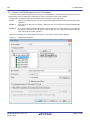
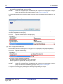
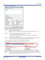
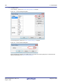
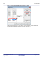
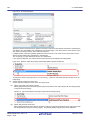
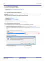
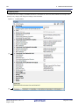
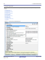
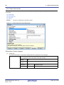
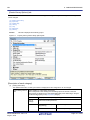
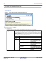
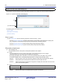
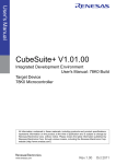
First, from the [Project] menu, select [Create New Project...], the Create Project dialog box will open.
Figure 2.1
Create Project Dialog Box
R20UT3284EJ0101 Rev.1.01
Aug 01, 2015
Page 9 of 204
CS+
2. FUNCTIONS
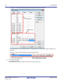
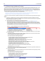
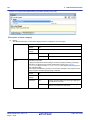
Set the items in the order below and click the [Create] button.
(1)
Select the microcontroller type
Select "RL78" on [Microcontroller].
(2)
Select the microcontroller
Select the microcontroller to use in the project on [Using microcontroller].
(3)
Select the project type
Under [Kind of project], select "Empty Application(CC-RL)" or "Library(CC-RL)", in accordance with the source
project.
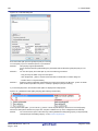
(4)
Specify the project name and location to create the project file
Specify the name of the project and the location to create the project file in [Project name] and [Place].
If you don’t create a folder with the project name under the specified location, clear the [Make the project folder]
check box.
Remark
(5)
It is recommended to specify the same folder as the diverted project for the location to create the
project file.
If a folder different from the diverted project is specified, there is a possibility that path determination fails and a build error is occurred.
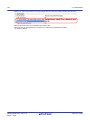
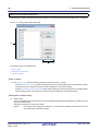
Specify the reuse of a CA78K0R project
Check [Pass the file composition of an existing project to the new project] and specify the location of the project
filename to reuse in [Project to be passed].
Remark
The result that a CC-RL project is created by reusing a CA78K0R project (the versions of the IDE and
compiler package, and conversion information of options) is output to a file as project divert information.
- The project divert information file name is "ProjectDivertInformationn.txt" (n = 2 to 100).
n is not added normally. It is added if the file to be created already exist.
- The project divert information file is output for each created project (subproject).
- The project divert information file is output to the project folder of the project (subproject).
- The project divert information file is added to the File node of the project (subproject) on the Project
Tree panel.
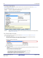
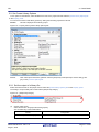
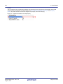
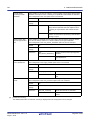
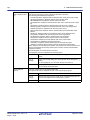
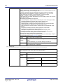
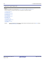
The output format of the project divert information file is shown below.
(1)Time and date on which a project was created
(2)<CS+ IDE(Integrated Development Environment Framework) version>
CS+ IDE: Version of IDE of CA78K0R project -> Version of IDE of CC-RL
project
(3)<Compiler package version>
CA78K0R: Version -> CC-RL: Version
(4)<Options not to use(Build mode)>
Command name(Tab name of build tool property)
Option
:
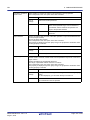
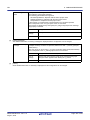
(5)<Options to change(Build mode)>
Command name(Tab name of build tool property)
Option of CA78K0R project -> Option of CC-RL project
:
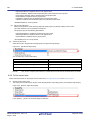
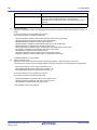
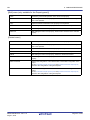
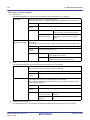
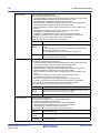
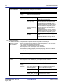
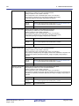
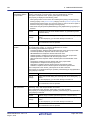
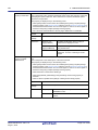
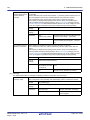
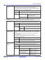
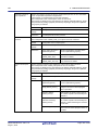
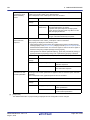
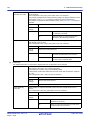
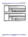
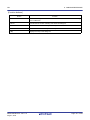
Number
Description
(1)
Time and date on which a project was created
The time and date on which a CC-RL project was created by reusing a CA78K0R project
is output using format "dddd, mmmm dd, yyyy hh:mm:ss AM/PM".
R20UT3284EJ0101 Rev.1.01
Aug 01, 2015
Page 10 of 204
CS+
2. FUNCTIONS
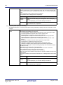
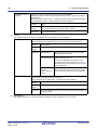
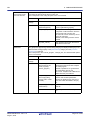
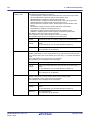
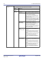
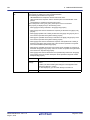
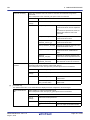
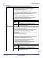
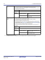
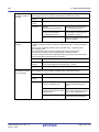
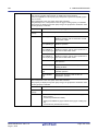
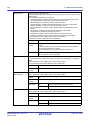
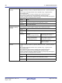
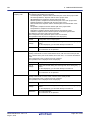
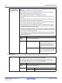
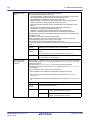
Number
Description
(2)
CS+ IDE(Integrated Development Environment Framework) version
The version of IDE of a CA78K0R project and the version of IDE of a CC-RL project are
output.
(3)
Compiler package version
The compiler package used in a CA78K0R project and the version, and the compiler
package used in a CC-RL project and the version are output.
The version of CC-RL is the latest version in the compiler packages which are installed in
the CS+ environment.
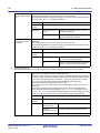
(4)
Options not to use(Build mode)
If an option that has been set in a CA78K0R project and is not used in a CC-RL project
exists, the information is output for each build mode in the format shown below.
Command name(Tab name of build tool property)
Option
:
- This item is output only when the corresponding option exists.
- CA78K0R options are converted into CC-RL options which have the same function.
The option that has the same function and different name is not output.
- Build modes are output in the following order: "DefaultBuild", user-created build mode
("DefaultBuild" is the build mode that CS+ provides by default).
See "CS+ Integrated Development Environment User’s Manual: Project Operation" for
detail about a build mode.
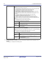
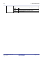
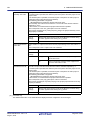
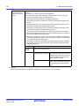
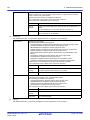
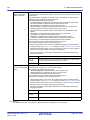
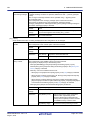
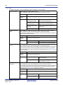
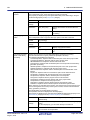
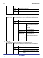
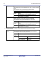
(5)
Options to change(Build mode)
If an option that has been set in a CA78K0R project and has been changed to use in a
CC-RL project exists (in the case that the function is same as CA78K0R, but the parameter does not exist in CC-RL, so it is changed to other one, and the like), the information
is output for each build mode in the format shown below.
Command name(Tab name of build tool property)
Option of CA78K0R project -> Option of CC-RL project
:
- This item is output only when the corresponding option exists.
- CA78K0R options are converted into CC-RL options which have the same function.
The option that has the same function and different name is not output.
- Build modes are output in the following order: "DefaultBuild", user-created build mode
("DefaultBuild" is the build mode that CS+ provides by default).
See "CS+ Integrated Development Environment User’s Manual: Project Operation" for
detail about a build mode.
R20UT3284EJ0101 Rev.1.01
Aug 01, 2015
Page 11 of 204
CS+
2. FUNCTIONS
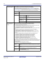
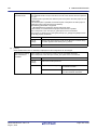
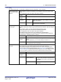
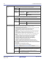
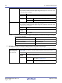
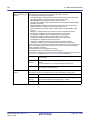
2.3 Speeding-up of Build
The build speed-up facilities of this build tool are described here.
There are the following types of build speed-up facilities.
Simultaneous build
Multiple files are simultaneously passed by a single call of the build command.
See "2.3.1 Running simultaneous build" for details about simultaneous build.
Parallel build
Multiple build commands are executed in parallel.
See "2.3.2 Running parallel build" for details about parallel build.
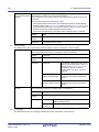
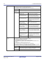
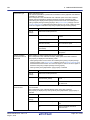
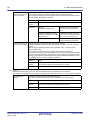
2.3.1 Running simultaneous build
Simultaneous build is a facility to simultaneously compile or assemble the files with a single call of the ccrl command
when there are multiple files to be built.
An image of calling the ccrl command is shown below.
Example
When build target files are aaa.c, bbb.c, and ccc.c
- When a build is run simultaneously
>ccrl aaa.c bbb.c ccc.c
<- "aaa.obj", "bbb.obj", and "ccc.obj" are
generated.
>rlink aaa.obj bbb.obj ccc.obj <- "aaa.abs" is generated.
- When a build is not run simultaneously
>ccrl aaa.c
>ccrl bbb.c
>ccrl ccc.c
>rlink aaa.obj bbb.obj ccc.obj
<<<<-
"aaa.obj"
"bbb.obj"
"ccc.obj"
"aaa.abs"
is
is
is
is
generated.
generated.
generated.
generated.
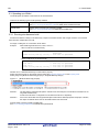
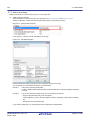
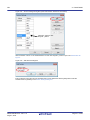
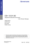
Whether to run a build simultaneously is made with the property.
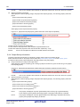
Select the build tool node on the project tree and select the [Common Options] tab on the Property panel.
Select [Yes] in the [Build simultaneously] property in the [Build Method] category.
Figure 2.2
[Build simultaneously] Property
Remark 1.
The files with the individual build options and files to be executed prior to the build are excluded from running build simultaneously.
A build of the file that is not targeted for a simultaneous build is run separately.
Remark 2.
If the source file is older than the generated object module file or related properties and project or the like,
the object module file will be used for the build instead of the source file.
Another facility to speed up build is parallel build.
See "2.3.2 Running parallel build" for details about parallel build.
R20UT3284EJ0101 Rev.1.01
Aug 01, 2015
Page 12 of 204
CS+
2. FUNCTIONS
2.3.2 Running parallel build
Parallel build is a facility to build multiple source files in parallel at build in order to reduce the build time.
In parallel build, since build is performed simultaneously for the number of logical CPUs in the host machine, the effect
is greater in a machine with a large number of CPU cores.
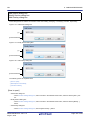
There are two types of parallel build facilities. Each processing and its setting method are given below.
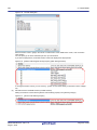
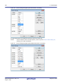
(1)
Parallel build between source files
When running parallel build between multiple source files registered in a project, make the setting in the [Build in
parallel] property in the [Common Options] tab on the Property panel.
Figure 2.3
Remark
(2)
[Build in parallel] Property
Another facility to speed up build is simultaneous build.
Simultaneous build is a facility to process the build command for multiple source files at once, and
specifying it simultaneously with parallel build has no effect due to its nature. Generally, the more
CPU cores there are in the host machine in use or the more source files there are registered in a
project, parallel build is faster than simultaneous build.
However, as there are properties that need to be used together with simultaneous build, such as
inter-module optimization, use the suitable facility for the situation.
See "2.3.1 Running simultaneous build" for details about simultaneous build.
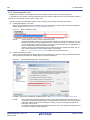
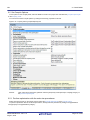
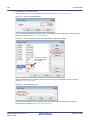
Parallel build between projects
When running parallel build between the main project and subprojects, make the setting in [Enable parallel build
among projects] of the [General - Build] category of the Option dialog box.
Figure 2.4
Option Dialog Box ([General - Build] Category)
In addition, select [Yes] in the [Build in parallel] property in the [Common Options] tab on the Property panel.
Remark
When there are dependencies between projects, set the dependencies between the projects correctly before using the parallel build facility. If a parallel build is performed for the main project and
subprojects without the dependencies being set, build is performed in parallel regardless of the
build order of the projects.
For details on setting the dependencies between projects, see "CS+ Integrated Development Environment User's Manual: Project Operation".
R20UT3284EJ0101 Rev.1.01
Aug 01, 2015
Page 13 of 204
CS+
2. FUNCTIONS
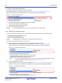
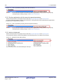
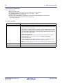
2.4 Set the Type of the Output File
Set the type of the file to be output as the product of the build.
Select the build tool node on the project tree and select the [Common Options] tab on the Property panel.
Select the file type in the [Output file type] property in the [Output File Type and Path] category.
Figure 2.5
[Output file type] Property
(1)
When [Execute Module(Load Module File)] is selected (Default)
The load module file will be the debug target.
(2)
When [Execute Module(Hex File)] is selected
The hex file will be the debug target.
Caution
For the library project, this property is always [Library] and cannot be changed.
2.4.1 Change the output file name
The names of the load module file, hex file, and library file output by the build tool are set as follows by default.
Load module file name: %ProjectName%.abs
Hex file name: %ProjectName%.mot
Library file name: lib%ProjectName%.lib
Remark
"%ProjectName%" is a placeholder. It is replaced with the project name.
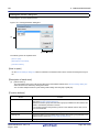
The method to change these file names is shown below.
(1)
When changing the load module file name and non-ROMized load module file name
Select the build tool node on the project tree and select the [Link Options] tab on the Property panel.
Enter the file name to be changed to in the [Output file name] property in the [Output File] category.
Figure 2.6
[Output file name] Property
This property supports the following placeholders.
%ActiveProjectName%: Replaces with the active project name.
%MainProjectName%: Replaces with the main project name.
%ProjectName%: Replaces with the project name.
Remark
(2)
You can also change the option in the same way with the [Output file name] property in the [Frequently Used Options(for Link)] category on the [Common Options] tab.
When changing the hex file name
Select the build tool node on the project tree and select the [Hex Output Options] tab on the Property panel.
Enter the hex file name to be changed to in the [Output file name] property in the [Output File] category.
Figure 2.7
[Output file name] Property
This property supports the following placeholders.
%ActiveProjectName%: Replaces with the active project name.
R20UT3284EJ0101 Rev.1.01
Aug 01, 2015
Page 14 of 204
CS+
2. FUNCTIONS
%MainProjectName%: Replaces with the main project name.
%ProjectName%: Replaces with the project name.
Remark
You can also change the option in the same way with the [Output file name] property in the [Frequently Used Options(for Hex Output)] category on the [Common Options] tab.
If the [Hex file format] property in the [Hex Format] category is changed, the following message dialog box will
open.
Figure 2.8
Message Dialog Box
When [Yes] is selected in the dialog box, the extension of the output file name is changed according to the format
selected in the [Hex file format] property.
Figure 2.9
(3)
[Output file name] and [Hex file format] Property
When changing the library file name
Select the build tool node on the project tree and select the [Create Library Options] tab on the Property panel.
Enter the library file name to be changed to on the [Output file name] property in the [Output File] category.
Figure 2.10 [Output file name] Property
This property supports the following placeholders.
%ActiveProjectName%: Replaces with the active project name.
%MainProjectName%: Replaces with the main project name.
%ProjectName%: Replaces with the project name.
Remark
You can also change the option in the same way with the [Output file name] property in the [Frequently Used Options(for Create Library)] category on the [Common Options] tab.
If the [Output file format] property is changed, the following message dialog box will open.
R20UT3284EJ0101 Rev.1.01
Aug 01, 2015
Page 15 of 204
CS+
2. FUNCTIONS
Figure 2.11
Message Dialog Box
When [Yes] is selected in the dialog box, the extension of the output file name is changed according to the format
selected in the [Output file format] property.
Figure 2.12 [Output file format] and [Output file name] Property
2.4.2 Output an assemble list
The assemble list (the code of the assemble result) is output to the assemble list file.
Select the build tool node on the project tree and select the [Compile Options] tab on the Property panel.
To output the assemble list file, select [Yes(-asm_option=-prn_path)] in the [Output assemble list file] property in the
[Assemble List] category.
Figure 2.13 [Output assemble list file] Property
When outputting the assemble list file, you can set the output folder and output file name.
(1)
Set the output folder
Setting the output folder is made with the [Output folder for assemble list file] property by directly entering in the
text box or by the [...] button.
This property supports the following placeholder.
%BuildModeName%: Replaces with the build mode name.
"%BuildModeName%" is set by default.
The file name will be the source file name with the extension replaced by ".prn".
Remark
See "CC-RL Compiler User’s Manual" for details about the assemble list file.
2.4.3 Output map information
The map information (the information of the link result) is output to the link map file.
Select the build tool node on the project tree and select the [Link Options] tab on the Property panel.
To output the link map file, set the [Output link map file] property in the [List] category.
(1)
Output information according to the output format
Select [Yes(List contents=not specify)(-LISt -SHow)] or [Yes(List contents=ALL)(-LISt -SHow=ALL)] in the [Output
link map file] property.
Figure 2.14 [Output link map file] Property (When Information According To Output Format Is Output)
R20UT3284EJ0101 Rev.1.01
Aug 01, 2015
Page 16 of 204
CS+
2. FUNCTIONS
Remark
(2)
See "CC-RL Compiler User’s Manual" for differences between the -SHow and -SHow=ALL options.
Specify information to be output
Select [Yes(List contents=specify)(-LISt)] in the [Output link map file] property. The following property will be displayed.
- [Output symbol information] property
- [Output number of symbol reference] property
- [Output cross reference information] property
- [Output total sizes of sections] property
- [Output vector information] property
Select [Yes] for each output information property.
Figure 2.15 [Output link map file] Property (When Information To Be Output Is Specified)
The link map file is output to the project folder.
It is also shown on the project tree, under the Build tool generated files node.
The file name will be the project file name with the extension replaced by ".map".
Remark
See "CC-RL Compiler User’s Manual" for details about the link map file.
2.4.4 Output library information
The library information (information from the library creation result) is output to the library list file.
Select the build tool node on the project tree and select the [Create Library Options] tab on the Property panel.
To output the library list file, set the [Output link map file] property in the [List] category.
(1)
Output information according to the output format
Select [Yes(List contents=not specify)(-LISt -SHow)] or [Yes(List contents=ALL)(-LISt -SHow=ALL)] in the [Output
link map file] property.
Figure 2.16 [Output link map file] Property (When Information According To Output Format Is Output)
Remark
(2)
See "CC-RL Compiler User’s Manual" for differences between the -SHow and -SHow=ALL options.
Specify information to be output
Select [Yes(List contents=specify)(-LISt)] in the [Output link map file] property. The following property will be displayed.
- [Output symbol information] property
- [Output section list in a module] propertyNote 1
- [Output cross reference information] propertyNote 2
- [Output total sizes of sections] propertyNote 2
Note 1.
This property is displayed only when [User libraries(-FOrm=Library=U)] or [System libraries(FOrm=Library=S)] in the [Output file format] property in the [Output File] category is selected.
Note 2.
This property is displayed only when [Relocate file(-FOrm=Relocate)] in the [Output file format]
property in the [Output File] category is selected.
R20UT3284EJ0101 Rev.1.01
Aug 01, 2015
Page 17 of 204
CS+
2. FUNCTIONS
Select [Yes] for each output information property.
Figure 2.17 [Output link map file] Property (When Information To Be Output Is Specified)
The library list file is output to the project folder.
It is also shown on the project tree, under the Build tool generated files node.
The file name will be the project file name with the extension replaced by ".lbp".
Remark
See "CC-RL Compiler User’s Manual" for details about the library list file.
R20UT3284EJ0101 Rev.1.01
Aug 01, 2015
Page 18 of 204
CS+
2. FUNCTIONS
2.5 Set Compile Options
To set options for the compile phase, select the Build tool node on the project tree and select the [Compile Options] tab
on the Property panel.
You can set the various compile options by setting the necessary properties in this tab.
Figure 2.18 Property Panel: [Compile Options] Tab
Remark
Often used options have been gathered under the [Frequently Used Options(for Compile)] category on
the [Common Options] tab.
2.5.1 Perform optimization with the code size precedence
Select the build tool node on the project tree and select the [Compile Options] tab on the Property panel.
To perform optimization with the code size precedence, select [Code size precedence(-Osize)] in the [Optimization
Level] property in the [Optimization] category.
R20UT3284EJ0101 Rev.1.01
Aug 01, 2015
Page 19 of 204
CS+
2. FUNCTIONS
Figure 2.19 [Level of optimization] Property (Code Size Precedence)
Remark
You can also set the option in the same way with the [Optimization Level] property in the [Frequently
Used Options(for Compile)] category on the [Common Options] tab.
2.5.2 Perform optimization with the execution speed precedence
Select the build tool node on the project tree and select the [Compile Options] tab on the Property panel.
To perform optimization with the execution speed precedence, select [Speed precedence(-Ospeed)] in the [Optimization
Level] property in the [Optimization] category.
Figure 2.20 [Level of optimization] Property (Execution Speed Precedence)
Remark
You can also set the option in the same way with the [Optimization Level] property in the [Frequently
Used Options(for Compile)] category on the [Common Options] tab.
2.5.3 Add an include path
Select the build tool node on the project tree and select the [Compile Options] tab on the Property panel.
The include path setting is made with the [Additional include paths] property in the [Preprocess] category.
Figure 2.21 [Additional include paths] Property
If you click the [...] button, the Path Edit dialog box will open.
R20UT3284EJ0101 Rev.1.01
Aug 01, 2015
Page 20 of 204
CS+
2. FUNCTIONS
Figure 2.22 Path Edit Dialog Box
Enter the include path per line in [Path(One path per one line)].
You can specify up to 247 characters per line, up to 256 lines.
Remark 1.
This property supports placeholders.
If a line is double clicked in [Placeholder], the placeholder will be reflected in [Path(One path per one
line)].
Remark 2.
You can also specify the include path by one of the following procedures.
- Drag and drop the folder using such as Explorer.
- Click the [Browse...] button, and then select the folder in the Browse For Folder dialog box.
- Double click a row in [Placeholder].
Remark 3.
Select the [Include subfolders automatically] check box before clicking the [Browse...] button to add all
paths under the specified one (down to 5 levels) to [Path(One path per one line)].
If you click the [OK] button, the entered include paths are displayed as subproperties.
Figure 2.23 [Additional include paths] Property (After Adding Include Paths)
To change the include paths, you can use the [...] button or enter the path directly in the text box of the subproperty.
When the include path is added to the project tree, the path is added to the top of the subproperties automatically.
Remark
You can also set the option in the same way with the [Additional include paths] property in the [Frequently
Used Options(for Compile)] category on the [Common Options] tab.
R20UT3284EJ0101 Rev.1.01
Aug 01, 2015
Page 21 of 204
CS+
2. FUNCTIONS
2.5.4 Set a macro definition
Select the build tool node on the project tree and select the [Compile Options] tab on the Property panel.
The macro definition setting is made with the [Macro definition] property in the [Preprocess] category.
Figure 2.24 [Macro definition] Property
If you click the [...] button, the Text Edit dialog box will open.
Figure 2.25 Text Edit Dialog Box
Enter the macro definition in [Text] in the format of "macro name=defined value", with one macro name per line.
You can specify up to 256 characters per line, up to 256 lines.
The "=defined value" part can be omitted, and in this case, "1" is used as the defined value.
If you click the [OK] button, the entered macro definitions are displayed as subproperties.
Figure 2.26 [Macro definition] Property (After Setting Macros)
To change the macro definitions, you can use the [...] button or enter the path directly in the text box of the subproperty.
Remark
You can also set the option in the same way with the [Macro definition] property in the [Frequently Used
Options(for Compile)] category on the [Common Options] tab.
R20UT3284EJ0101 Rev.1.01
Aug 01, 2015
Page 22 of 204
CS+
2. FUNCTIONS
2.6 Set Assemble Options
To set options for the assemble phase, select the Build tool node on the project tree and select the [Assemble Options]
tab on the Property panel.
You can set the various assemble options by setting the necessary properties in this tab.
Figure 2.27 Property Panel: [Assemble Options] Tab
Remark
Often used options have been gathered under the [Frequently Used Options(for Assemble)] category on
the [Common Options] tab.
Caution
This tab is displayed only when [No] in the [Build simultaneously] property in the [Build Method] category
from the [Common Options] tab is selected.
2.6.1 Add an include path
Select the build tool node on the project tree and select the [Assemble Options] tab on the Property panel.
The include path setting is made with the [Additional include paths] property in the [Preprocess] category.
Figure 2.28 [Additional include paths] Property
If you click the [...] button, the Path Edit dialog box will open.
R20UT3284EJ0101 Rev.1.01
Aug 01, 2015
Page 23 of 204
CS+
2. FUNCTIONS
Figure 2.29 Path Edit Dialog Box
Enter the include path per line in [Path(One path per one line)].
You can specify up to 247 characters per line, up to 256 lines.
Remark 1.
This property supports placeholders.
If a line is double clicked in [Placeholder], the placeholder will be reflected in [Path(One path per one
line)].
Remark 2.
You can also specify the include path by one of the following procedures.
- Drag and drop the folder using such as Explorer.
- Click the [Browse...] button, and then select the folder in the Browse For Folder dialog box.
- Double click a row in [Placeholder].
Remark 3.
Select the [Include subfolders automatically] check box before clicking the [Browse...] button to add all
paths under the specified one (down to 5 levels) to [Path(One path per one line)].
If you click the [OK] button, the entered include paths are displayed as subproperties.
Figure 2.30 [Additional include paths] Property (After Adding Include Paths)
To change the include paths, you can use the [...] button or enter the path directly in the text box of the subproperty.
When the include path is added to the project tree, the path is added to the top of the subproperties automatically.
Remark
You can also set the option in the same way with the [Additional include paths] property in the [Frequently
Used Options(for Assemble)] category on the [Common Options] tab.
R20UT3284EJ0101 Rev.1.01
Aug 01, 2015
Page 24 of 204
CS+
2. FUNCTIONS
2.6.2 Set a macro definition
Select the build tool node on the project tree and select the [Assemble Options] tab on the Property panel.
The macro definition setting is made with the [Macro definition] property in the [Preprocess] category.
Figure 2.31 [Macro definition] Property
If you click the [...] button, the Text Edit dialog box will open.
Figure 2.32 Text Edit Dialog Box
Enter the macro definition in [Text] in the format of "macro name=defined value", with one macro name per line.
You can specify up to 256 characters per line, up to 256 lines.
The "=defined value" part can be omitted, and in this case, "1" is used as the defined value.
If you click the [OK] button, the entered macro definitions are displayed as subproperties.
Figure 2.33 [Macro definition] Property (After Setting Macros)
To change the macro definitions, you can use the [...] button or enter the path directly in the text box of the subproperty.
Remark
You can also set the option in the same way with the [Macro definition] property in the [Frequently Used
Options(for Assemble)] category on the [Common Options] tab.
R20UT3284EJ0101 Rev.1.01
Aug 01, 2015
Page 25 of 204
CS+
2. FUNCTIONS
2.7 Set Link Options
To set options for the link phase, select the Build tool node on the project tree and select the [Link Options] tab on the
Property panel.
You can set the various link options by setting the necessary properties in this tab.
Caution
This tab is not displayed for the library project.
Figure 2.34 Property Panel: [Link Options] Tab
Remark
Often used options have been gathered under the [Frequently Used Options(for Link)] category on the
[Common Options] tab.
R20UT3284EJ0101 Rev.1.01
Aug 01, 2015
Page 26 of 204
CS+
2. FUNCTIONS
2.7.1 Add a user library
Adding a user library is made with the property or on the project tree.
(1)
Addition using the property
Select the build tool node on the project tree and select the [Link Options] tab on the Property panel.
Adding a user library is made with the [Using libraries] property in the [Library] category.
Figure 2.35 [Using libraries] Property
If you click the [...] button, the Path Edit dialog box will open.
Figure 2.36 Path Edit Dialog Box
Enter the library file (including the path) per line in [Path(One path per one line)].
You can specify up to 259 characters per line, up to 65536 lines.
Remark 1.
This property supports placeholders.
If a line is double clicked in [Placeholder], the placeholder will be reflected in [Path(One path per
one line)].
Remark 2.
You can also specify the library file by one of the following procedures.
- Drag and drop the folder using such as Explorer.
- Click the [Browse...] button, and then select the folder in the Specify Using Library File dialog
box.
- Double click a row in [Placeholder].
If you click the [OK] button, the entered library files are displayed as subproperties.
R20UT3284EJ0101 Rev.1.01
Aug 01, 2015
Page 27 of 204
CS+
2. FUNCTIONS
Figure 2.37 [Using libraries] Property (After Setting Library Files)
To change the library files, you can use the [...] button or enter the path directly in the text box of the subproperty.
Remark
(2)
You can also set the option in the same way with the [Using libraries] property in the [Frequently
Used Options(for Link)] category on the [Common Options] tab.
Addition from the project tree
Adding a library file to the project tree is performed from the Add Existing File dialog box.
Dropping a library file in the project tree is also possible.
When a library file is added from the project tree, it is subject to timestamp comparison with the load module at
build, and the link processing is executed when the added library file is updated.
2.7.2 Prepare for using the overlaid section selection function
The optimizing linker (rlink) used by CC-RL can allocate multiple sections defined in a program to the same address.
The sections allocated in this way are called "overlaid sections".
The debug tool provides a function to select the debug target section from the overlaid sections (priority sections) allocated to the same address. The function is called "overlaid section selection function".
A load module using overlaid sections can be debugged with switching of the priority section before program execution.
The method for generating a load module to use the overlaid section selection function is shown below.
(1)
Copy the ROM area contents to RAM
Copy the ROM area contents to the RAM area to expand the code and data in the RAM.
(2)
Set build options
Set the ROM-to-RAM mapped sections and overlaid sections to use the overlaid section selection function.
Select the build tool node on the project tree and select the [Link Options] tab on the Property panel.
(a)
Set ROM-to-RAM mapped sections
Setting the ROM-to-RAM mapped sections is made with the [ROM to RAM mapped section] property in the
[Section] category.
This reserves the RAM section with the same size as that of the ROM section and relocates the symbols
defined in the ROM section to addresses in the RAM section.
Figure 2.38 [ROM to RAM mapped section] Property
If you click the [...] button, the Text Edit dialog box will open.
R20UT3284EJ0101 Rev.1.01
Aug 01, 2015
Page 28 of 204
CS+
2. FUNCTIONS
Figure 2.39 Text Edit Dialog Box
Enter the section name in [Text] in the format of "ROM section name=RAM section name", with one section
name per line.
You can specify up to 32767 characters per line, up to 65535 lines.
If you click the [OK] button, the entered section names are displayed as subproperties.
Figure 2.40 [ROM to RAM mapped section] Property (After Setting Sections)
To change the section names, you can use the [...] button or enter them directly in the text box of the subproperty.
(b)
Set ROM sections and RAM sections (overlaid sections)
Setting the sections is made with the [Section start address] property in the [Section] category.
Figure 2.41 [Section start address] Property
R20UT3284EJ0101 Rev.1.01
Aug 01, 2015
Page 29 of 204
CS+
2. FUNCTIONS
<1> Set ROM sections
If you click the [...] button, the Section Settings dialog box will open.
Figure 2.42 Section Settings Dialog Box
If you click the [Add...] button, the Section Address dialog box will open.
Figure 2.43 Section Address Dialog Box
Enter in [Address] the address of the ROM section to be added and click the [OK] button to add the entered
address to [Address] in the Section Settings dialog box.
R20UT3284EJ0101 Rev.1.01
Aug 01, 2015
Page 30 of 204
CS+
2. FUNCTIONS
Figure 2.44 Section Settings Dialog Box (After ROM Section Addresses Are Added)
Click here, and then click
the [Add...] button.
Click the Section column on the added address row and click the [Add...] button to open the Add Section dialog box.
Figure 2.45 Add Section Dialog Box
Enter in [Section name] the name of the ROM section to be added and click the [OK] button to add the
entered section to [Section] in the Section Settings dialog box.
R20UT3284EJ0101 Rev.1.01
Aug 01, 2015
Page 31 of 204
CS+
2. FUNCTIONS
Figure 2.46 Section Settings Dialog Box (After ROM Sections Are Added)
For other ROM sections, set addresses and section names in the same way.
Remark
Click the Address column and click the [Add...] button to open the Section Address dialog box,
allowing you to add a new address.
Figure 2.47 Section Settings Dialog Box (After Multiple ROM Sections Are Added)
R20UT3284EJ0101 Rev.1.01
Aug 01, 2015
Page 32 of 204
CS+
2. FUNCTIONS
<2> Set RAM sections (overlaid sections)
Click an added address and click the [Add...] button to open the Section Address dialog box.
Figure 2.48 Section Address Dialog Box
Enter in [Address] the address of the RAM section to be added and click the [OK] button to add the entered
address to [Address] in the Section Settings dialog box.
Figure 2.49 Section Settings Dialog Box (After RAM Section Addresses Are Added)
Click here, and then
click the [New Overlay...] button.
Click the added address row (Address column or Section column) and click the [New Overlay...] button to
open the Add Overlay dialog box.
Figure 2.50 Add Overlay Dialog Box
Enter in [Section name] the name of the RAM section to be added and click the [OK] button to add the
entered section to [Section] in the Section Settings dialog box.
R20UT3284EJ0101 Rev.1.01
Aug 01, 2015
Page 33 of 204
CS+
2. FUNCTIONS
Figure 2.51 Section Settings Dialog Box (After RAM Sections Are Added)
Click here, and then
click the [New Overlay...] button.
Add the sections to be allocated to the same address by using the [New Overlay...] button in the same way.
The added sections are displayed under [Overlay n] (n: number starting with "1").
R20UT3284EJ0101 Rev.1.01
Aug 01, 2015
Page 34 of 204
CS+
2. FUNCTIONS
Figure 2.52 Section Settings Dialog Box (After Overlaid Sections Are Added)
For other RAM sections, set addresses and section names in the same way.
Remark
Click the Address column and click the [Add...] button to open the Section Address dialog box,
allowing you to add a new address.
R20UT3284EJ0101 Rev.1.01
Aug 01, 2015
Page 35 of 204
CS+
2. FUNCTIONS
Figure 2.53 Section Settings Dialog Box (After Multiple RAM Sections Are Added)
ROM sections
RAM sections
Click the [OK] button. The specified ROM sections and RAM sections (overlaid sections) will be displayed in the
text boxes.
Figure 2.54 [Section start address] Property (After Setting Sections)
(3)
Run a build of the project
Run a build of the project.
A load module file to use the overlaid section selection function is generated.
R20UT3284EJ0101 Rev.1.01
Aug 01, 2015
Page 36 of 204
CS+
2. FUNCTIONS
2.8 Set Hex Output Options
To set options for the hex output phase, select the Build tool node on the project tree and select the [Hex Output
Options] tab on the Property panel.
You can set the various hex output options by setting the necessary properties in this tab.
Caution
This tab is not displayed for the library project.
Figure 2.55 Property Panel: [Hex Output Options] Tab
Remark
Often used options have been gathered under the [Frequently Used Options(for Hex Output)] category
on the [Common Options] tab.
2.8.1 Set the output of a hex file
Select the build tool node on the project tree and select the [Hex Output Options] tab on the Property panel.
(1)
Set the output of a hex file
The setting to output a hex file is made with the [Output hex file] property in the [Output File] category.
To output a hex file, select [Yes], to not output a hex file, select [No].
Figure 2.56 [Output hex file] Property
When outputting a hex file, you can set the output folder and output file name.
(a)
Set the output folder
Setting the output folder is made with the [Output folder] property by directly entering to the text box or by the
[...] button.
Up to 247 characters can be specified in the text box.
This property supports the following placeholder.
%ActiveProjectDir%: Replaces with the absolute path of the active project folder.
%ActiveProjectName%: Replaces with the active project name.
%BuildModeName%: Replaces with the build mode name.
%MainProjectDir%: Replaces with the absolute path of the main project folder.
R20UT3284EJ0101 Rev.1.01
Aug 01, 2015
Page 37 of 204
CS+
2. FUNCTIONS
%MainProjectName%: Replaces with the main project name.
%MicomToolPath%: Replaces with the absolute path of the install folder of this product.
%ProjectDir%: Replaces with the absolute path of the project folder.
%ProjectName%: Replaces with the project name.
%TempDir%: Replaces with the absolute path of the temporary folder.
%WinDir%: Replaces with the absolute path of the Windows system folder.
"%BuildModeName%" is set by default.
(b)
Set the output file name
Setting the output file is made with the [Output file name] property by directly entering to the text box.
Up to 259 characters can be specified in the text box.
This property supports the following placeholders.
%ActiveProjectName%: Replaces with the active project name.
%MainProjectName%: Replaces with the main project name.
%ProjectName%: Replaces with the project name.
"%ProjectName%.mot" is set by default.
(2)
Set the hex file format
Select the format in the [Hex file format] property in the [Hex Format] category.
Figure 2.57 [Hex file format] Property
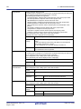
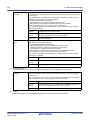
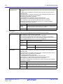
You can select any of the formats below.
Format
Configuration
Intel HEX file(-FOrm=Hexadecimal)
Outputs an Intel HEX file.
Motorola S-record file(-FOrm=Stype)
Outputs a Motorola S-record file.
Binary file(-FOrm=Binary)
Outputs a binary file.
Remark
See "CC-RL Compiler User’s Manual" for details about the Intel Hex file and Motorola S-record file.
2.8.2 Fill the vacant area
Select the build tool node on the project tree and select the [Hex Output Options] tab on the Property panel.
(1)
Set the hex file output range
The setting of the hex file output range is made with the [Division output file] property in the [Output File] category.
Figure 2.58 [Division output file] Property
If you click the [...] button, the Text Edit dialog box will open.
R20UT3284EJ0101 Rev.1.01
Aug 01, 2015
Page 38 of 204
CS+
2. FUNCTIONS
Figure 2.59 Text Edit Dialog Box
Specify the division output file name in [Text] in the format of "file name=start address-end address" (start address,
end address: The start address and end address of the output range) or "file name=section name" (section name:
The name of the output section), with one file name per line.
If multiple section names are specified, delimit them with a colon as in "file name=section name:section name".
Specify the start address and end address in hexadecimal.
You can specify up to 259 characters per line, up to 65535 lines.
If you click the [OK] button, the entered division output file names are displayed as subproperties.
Figure 2.60 [Division output file] Property (After Setting Division Output File Names)
To change the division output file names, you can use the [...] button or enter them directly in the text box of the
subproperty.
(2)
(a)
Set the method for filling the vacant area
Set the method for filling the vacant area in the output range.
Fill the vacant area with random numbers
Select [Yes(Random)(-SPace=Random)] in the [Fill unused areas in the output ranges with the value] property
in the [Hex Format] category.
Figure 2.61 [Fill unused areas in the output ranges with the value] Property
(b)
Specify data to fill the vacant area
Select [Yes(Specification value)(-SPace=<Numerical value>)] in the [Fill unused areas in the output ranges with
the value] property in the [Hex Format] category. The [Output padding data] property will be displayed.
R20UT3284EJ0101 Rev.1.01
Aug 01, 2015
Page 39 of 204
CS+
2. FUNCTIONS
Figure 2.62 [Fill unused areas in the output ranges with the value] and [Output padding data] Property
Enter the fill value for the vacant area directly in the text box.
The range that can be specified for the value is 00 to FFFFFFFF (hexadecimal number).
"FF" is set by default.
R20UT3284EJ0101 Rev.1.01
Aug 01, 2015
Page 40 of 204
CS+
2. FUNCTIONS
2.9 Set Create Library Options
To set options for the librarian, select the Build tool node on the project tree and select the [Create Library Options] tab
on the Property panel.
You can set the various create library options by setting the necessary properties in this tab.
Caution
This tab is displayed for the library project.
Figure 2.63 Property Panel: [Create Library Options] Tab
Remark
Often used options have been gathered under the [Frequently Used Options(for Create Library)] category on the [Common Options] tab.
2.9.1 Set the output of a library file
Select the build tool node on the project tree and select the [Create Library Options] tab on the Property panel.
The setting to output a library file is made with the [Output File] category.
Figure 2.64 [Output File] Category
(1)
Set the output format
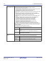
Select the format in the [Output file format] property.
You can select any of the formats below.
Format
User libraries(-FOrm=Library=U)
R20UT3284EJ0101 Rev.1.01
Aug 01, 2015
Configuration
Outputs a user library file.
Page 41 of 204
CS+
2. FUNCTIONS
Format
(2)
Configuration
System libraries(-FOrm=Library=S)
Outputs a system library file.
The system library file is linked after the user library file.
Select this item to create a library that is to be linked after the user
library file.
Relocatable file(-FOrm=Relocate)
Outputs a relocatable file.
Set the output folder
Setting the output folder is made with the [Output folder] property by directly entering to the text box or by the [...]
button.
Up to 247 characters can be specified in the text box.
This property supports the following placeholder.
%ActiveProjectDir%: Replaces with the absolute path of the active project folder.
%ActiveProjectName%: Replaces with the active project name.
%BuildModeName%: Replaces with the build mode name.
%MainProjectDir%: Replaces with the absolute path of the main project folder.
%MainProjectName%: Replaces with the main project name.
%MicomToolPath%: Replaces with the absolute path of the install folder of this product.
%ProjectDir%: Replaces with the absolute path of the project folder.
%ProjectName%: Replaces with the project name.
%TempDir%: Replaces with the absolute path of the temporary folder.
%WinDir%: Replaces with the absolute path of the Windows system folder.
"%BuildModeName%" is set by default.
(3)
Set the output file name
Setting the output file is made with the [Output file name] property by directly entering to the text box.
If the extension is omitted, it is automatically added according to the selection in the [Output file format] property.
When [User libraries(-FOrm=Library=U)] is selected: .lib
When [System libraries(-FOrm=Library=S)] is selected: .lib
When [Relocatable file(-FOrm=Relocate)] is selected: .rel
Up to 259 characters can be specified in the text box.
This property supports the following placeholders.
%ActiveProjectName%: Replaces with the active project name.
%MainProjectName%: Replaces with the main project name.
%ProjectName%: Replaces with the project name.
"%ProjectName%.lib" is set by default.
R20UT3284EJ0101 Rev.1.01
Aug 01, 2015
Page 42 of 204
CS+
2. FUNCTIONS
2.10 Set Build Options Separately
Build options are set at the project or file level.
Project level: See "2.10.1 Set build options at the project level"
File level: See "2.10.2 Set build options at the file level"
2.10.1 Set build options at the project level
To set options for build options for the project (main project or subproject), select the Build tool node on the project tree
to display the Property panel.
Select the phase tab and set build options by setting the necessary properties.
Compile phase: [Compile Options] tab
Assemble phase: [Assemble Options] tab
Link phase: [Link Options] tab
Hex output phase: [Hex Output Options] tab
Create library phase: [Create Library Options] tab
I/O header file generation tool: [I/O Header File Generation Options] tab
2.10.2 Set build options at the file level
You can individually set compile and assemble options for each source file added to the project.
(1)
When setting compile options for a C source file
Select the C source file on the project tree and select the [Build Settings] tab on the Property panel.
Select [Yes] in the [Set individual compile option] property in the [Build] category. The Message Dialog Box will
open.
Figure 2.65 [Set individual compile option] Property
Figure 2.66 Message Dialog Box
Click [Yes] in the dialog box. The [Individual Compile Options] tab will be displayed.
R20UT3284EJ0101 Rev.1.01
Aug 01, 2015
Page 43 of 204
CS+
2. FUNCTIONS
Figure 2.67 Property Panel: [Individual Compile Options] Tab
You can set compile options for the C source file by setting the necessary properties in this tab.
Note that this tab takes over the settings of the [Common Options] tab and [Compile Options] tab by default except
the properties shown below.
- [Additional include paths] and [Use whole include paths specified for build tool] in the [Preprocess] category
- [Object module file name] in the [Output File] category
(2)
When setting assemble options for an assembly source file
Select the assembly source file on the project tree and select the [Build Settings] tab on the Property panel.
Select [Yes] in the [Set individual assemble option] property in the [Build] category. The Message Dialog Box will
open.
R20UT3284EJ0101 Rev.1.01
Aug 01, 2015
Page 44 of 204
CS+
2. FUNCTIONS
Figure 2.68 [Set individual assemble option] Property
Figure 2.69 Message Dialog Box
Click [Yes] in the dialog box. The [Individual Assemble Options] tab will be displayed.
Figure 2.70 Property Panel: [Individual Assemble Options] Tab
You can set assemble options for the assembly source file by setting the necessary properties in this tab.
Note that this tab takes over the settings of the [Common Options] tab and [Compile Options] tab/[Assemble
Options] tab by default except the properties shown below.
- [Additional include paths] and [Use whole include paths specified for build tool] in the [Preprocess] category
- [Object module file name] in the [Output File] category
R20UT3284EJ0101 Rev.1.01
Aug 01, 2015
Page 45 of 204
CS+
2. FUNCTIONS
2.11 Efficiently Allocate Variables and Functions
Generate and use the variables/functions information header file to efficiently allocate variables and functions. A variables/functions information header file (header file used to efficiently assign the saddr area and callt area based on the
number of times and order in which the variables and functions are referenced) is generated by setting the [Output variables/functions information header file] property from the [Link Options] tab on the Property panel. Variables will be allocated to the saddr area, and functions to the callt area by performing compilation using that file.
The procedures for performing this operation are described below.
- Generating a variables/functions information header file automatically and allocating variables and functions
- Editing and using an auto-generated variables/functions information header file
Make sure to confirm that build has completed successfully and a load module file has been generated before using this
function.
(1)
Generating a variables/functions information header file automatically and allocating variables and functions
Below is the procedure for generating a variables/functions information header file automatically and using that file
to allocate variables and functions, via one build.
(a)
Set the generation of the variables/functions information header file
Select the build tool node on the project tree and select the [Link Options] tab on the Property panel.
Set the [Output variables/functions information header file] property to [Yes] to generate an empty variables/
functions information header file, and add it to the project (it will also appear in the File node of the project tree).
The output destination is the file set in the [Output folder for variables/functions information header file] property
and the [Variables/functions information header file name] property.
Figure 2.71 [Output variables/functions information header file] Property
The settings of the output folder and file of the variables/functions information header file are can be changed.
<1> Set the output folder
Setting the output folder is made with the [Output folder for variables/functions information header file] property by directly entering to the text box or by the [...] button.
Up to 247 characters can be specified in the text box.
This property supports the following placeholders.
%ActiveProjectDir%: Replaces with the absolute path of the active project folder.
%ActiveProjectName%: Replaces with the active project name.
%BuildModeName%: Replaces with the build mode name.
%MainProjectDir%: Replaces with the absolute path of the main project folder.
%MainProjectName%: Replaces with the main project name.
%MicomToolPath%: Replaces with the absolute path of the install folder of this product.
%ProjectDir%: Replaces with the absolute path of the project folder.
%ProjectName%: Replaces with the project name.
%TempDir%: Replaces with the absolute path of the temporary folder.
%WinDir%: Replaces with the absolute path of the Windows system folder.
"%BuildModeName%" is set by default.
If this property is changed, an empty variables/functions information header file is generated and added to the
project (it will also appear in the File node of the project tree).
<2> Set the output file name
Setting the output file is made with the [Variables/functions information header file name] property by directly
entering to the text box.
Up to 259 characters can be specified in the text box.
This property supports the following placeholders.
%ActiveProjectName%: Replaces with the active project name.
%MainProjectName%: Replaces with the main project name.
%ProjectName%: Replaces with the project name.
"%ProjectName%_vfi.h" is set by default.
R20UT3284EJ0101 Rev.1.01
Aug 01, 2015
Page 46 of 204
CS+
2. FUNCTIONS
If this property is changed, an empty variables/functions information header file is generated and added to the
project (it will also appear in the File node of the project tree).
(b)
Run a build of the project
Run a build of the project.
A variables/functions information header file is generated. It will be included in the C source automatically and a
rebuild will be executed again.
Remark
The variables/functions information header file in "(a) Set the generation of the variables/functions information header file" is overwritten by running a build.
If the build completes successfully, a load module file is generated with the variables and functions allocated.
(2)
(a)
Editing and using an auto-generated variables/functions information header file
Users can edit a variables/functions information header file.
Below is the procedure for editing the generated variables/functions information header file in "(1) Generating a
variables/functions information header file automatically and allocating variables and functions" by the user and
using that file to allocate variables and functions.
Edit the variables/functions information header file
Edit the variables/functions information header file generated automatically in "(1) Generating a variables/functions information header file automatically and allocating variables and functions".
Remark
(b)
See "CC-RL Compiler User’s Manual" for details about the format of the auto-generated variables/functions information header file.
Set the generation of the variables/functions information header file
Select the build tool node on the project tree and select the [Link Options] tab on the Property panel.
Select [No] on the [Output variables/functions information header file] property.
Figure 2.72 [Output variables/functions information header file] Property
Next, select the [Compile Options] tab.
Specify the edited variables/functions information header file on the [Include files at head of compiling units]
property.
Figure 2.73 [Include files at head of compiling units] Property
(c)
Run a build of the project
Run a build of the project.
A load module file is generated with the variables and functions allocated as specified in the variables/functions
information header file.
R20UT3284EJ0101 Rev.1.01
Aug 01, 2015
Page 47 of 204
CS+
2. FUNCTIONS
2.12 Automatically Update the I/O Header File
When an application project is newly created, an I/O header file corresponding to the selected device is automatically
generated.
If the I/O header file needs to be automatically updated in response to the update of the device file, use the following
update method.
The I/O header file is automatically generated as "iodefine.h" when an application project is newly created and it is registered in the project tree.
Figure 2.74 I/O Header File (iodefine.h)
Remark
The I/O header file is generated in the same folder containing the project file. If a file with the same name
already exists, the existing file is renamed as "iodefine.bak" as a backup.
The timing to update the I/O header file and the update method are shown below.
- At opening of the project
CS+ checks the version of the device file when a project is opened.
If the device file has been updated and there is a possibility that the I/O header file needs to be updated, a message
is displayed on the Output panel. Update the I/O header file with the method below as required.
- On the Project Tree panel, select the Build tool node, and then select [Generate I/O Header File] from the context menu
Figure 2.75 [Generate I/O Header File] Item
R20UT3284EJ0101 Rev.1.01
Aug 01, 2015
Page 48 of 204
CS+
2. FUNCTIONS
- At build
The I/O header file can be updated automatically when the build process is performed and immediately before build.
Set the [Update I/O header file on build] property of the [I/O Header File Generation Options] tab in the Property
panel. The update conditions can also be changed in the property of the same category.
Figure 2.76 [Update I/O header file on build] Property
R20UT3284EJ0101 Rev.1.01
Aug 01, 2015
Page 49 of 204
CS+
2. FUNCTIONS
2.13 Estimate the Stack Capacity
To estimate the stack capacity, use Call Walker.
Call Walker performs a static analysis, and displays the symbols and their callers in a tree format, as well as stack information for each symbol (symbol name, attribute, address, size, stack size, and file name) in list format.
To start Call Walker, select [Tool] menu >> [Startup Stack Usage Tracer].
To exit from Call Walker, select Call Walker [File] menu >> [Exit].
See Call Walker [Help] menu >> [Help Topics] for Call Walker operations.
R20UT3284EJ0101 Rev.1.01
Aug 01, 2015
Page 50 of 204
CS+
A. WINDOW REFERENCE
A. WINDOW REFERENCE
This appendix explains panels/dialog boxes used in the build tool.
A.1 Description
The following lists the panels/dialog boxes used in the build tool.
Table A.1
List of Panels/Dialog Boxes
Panel/Dialog Box Name
Function Description
Property panel
This panel is used to display the detailed information on the Build tool
node or file that is selected on the Project Tree panel and change the
settings of the information.
System Include Path Order dialog box
This dialog box is used to refer the system include paths specified for
the compiler and set their specified sequence.
Specify Rule Number dialog box
This dialog box is used to select the number of the MISRA-C rule and
set it to the area that this dialog box is called from.
Section Settings dialog box
This dialog box is used to add, modify, or delete sections.
Add Section dialog box
Modify Section dialog box
Add Overlay dialog box
These dialog boxes are used to set a section name when adding,
modifying, or overlaying a section, respectively.
Section Address dialog box
This dialog box is used to set an address when adding or modifying a
section.
Unassigned Section dialog box
This dialog box is used to delete sections.
R20UT3284EJ0101 Rev.1.01
Aug 01, 2015
Page 51 of 204
CS+
A. WINDOW REFERENCE
Property panel
This panel is used to display the detailed information on the Build tool node or file that is selected on the Project Tree
panel by every category and change the settings of the information.
Figure A.1
Property Panel
(1)
(2)
R20UT3284EJ0101 Rev.1.01
Aug 01, 2015
Page 52 of 204
CS+
A. WINDOW REFERENCE
The following items are explained here.
- [How to open]
- [Description of each area]
- [[Edit] menu (only available for the Property panel)]
- [Context menu]
[How to open]
- On the Project Tree panel, select the Build tool node or file and then select [Property] from the [View] menu or [Property] from the context menu.
Remark
When either one of the Build tool node or file on the Project Tree panel is selected while the Property
panel has been opened, the detailed information of the selected item is displayed.
[Description of each area]
(1)
Detailed information display/change area
In this area, the detailed information on the Build tool node or file that is selected on the Project Tree panel is displayed by every category in the list. And the settings of the information can be changed directly.
Mark
indicates that all the items in the category are expanded. Mark
indicates that all the items are collapsed. You can expand/collapse the items by clicking these marks or double clicking the category name.
Mark
indicates that only a hexadecimal number is allowed to input in the text box.
See the section on each tab for the details of the display/setting in the category and its contents.
(2)
Tab selection area
Categories for the display of the detailed information are changed by selecting a tab.
In this panel, the following tabs are contained (see the section on each tab for the details of the display/setting on
the tab).
Remark
(a)
When multiple components are selected on the Project Tree panel, only the tab that is common to
all the components is displayed.
If the value of the property is modified, that is taken effect to the selected components all of which
are common to all.
When the Build tool node is selected on the Project Tree panel
- [Common Options] tab
- [Compile Options] tab
- [Assemble Options] tab
- [Link Options] tab
- [Hex Output Options] tab
- [Create Library Options] tab
- [I/O Header File Generation Options] tab
(b)
When a file is selected on the Project Tree panel
- [Build Settings] tab (for C source file, assembly source file, object file, and library file)
- [Individual Compile Options] tab (for C source file)
- [Individual Assemble Options] tab (for assembly source file)
- [File Information] tabNote
Note
See "CS+ Integrated Development Environment User’s Manual: Project Operation" for details
about the [File Information] tab.
R20UT3284EJ0101 Rev.1.01
Aug 01, 2015
Page 53 of 204
CS+
A. WINDOW REFERENCE
[[Edit] menu (only available for the Property panel)]
Undo
Cancels the previous edit operation of the value of the property.
Cut
While editing the value of the property, cuts the selected characters and copies
them to the clipboard.
Copy
Copies the selected characters of the property to the clipboard.
Paste
While editing the value of the property, inserts the contents of the clipboard.
Delete
While editing the value of the property, deletes the selected characters.
Select All
While editing the value of the property, selects all the characters of the selected
property.
[Context menu]
Undo
Cancels the previous edit operation of the value of the property.
Cut
While editing the value of the property, cuts the selected characters and copies
them to the clipboard.
Copy
Copies the selected characters of the property to the clipboard.
Paste
While editing the value of the property, inserts the contents of the clipboard.
Delete
While editing the value of the property, deletes the selected characters.
Select All
While editing the value of the property, selects all the characters of the selected
property.
Reset to Default
Restores the configuration of the selected item to the default configuration of the
project.
For the [Individual Compile Options] tab and [Individual Assemble Options] tab,
restores to the configuration of the general option.
Reset All to Default
Restores all the configuration of the current tab to the default configuration of the
project.
For the [Individual Compile Options] tab and [Individual Assemble Options] tab,
restores to the configuration of the general option.
R20UT3284EJ0101 Rev.1.01
Aug 01, 2015
Page 54 of 204
CS+
A. WINDOW REFERENCE
[Common Options] tab
This tab shows the detailed information on the build tool categorized by the following and the configuration can be
changed.
(1) [Build Mode]
(2) [CPU]
(3) [Output File Type and Path]
(4) [Frequently Used Options(for Compile)]
(5) [Frequently Used Options(for Assemble)]
(6) [Frequently Used Options(for Link)]
(7) [Frequently Used Options(for Hex Output)]
(8) [Frequently Used Options(for Create Library)]
(9) [Error Output]
(10) [Warning Message]
(11) [Device]
(12) [Build Method]
(13) [Version Select]
(14) [Notes]
(15) [Others]
Remark
If the property in the [Frequently Used Options] category is changed, the value of the property having the
same name contained in the corresponding tab will be changed accordingly.
Category from [Common Options] Tab
Corresponding Tab
[Frequently Used Options(for Compile)] category
[Compile Options] tab
[Frequently Used Options(for Assemble)] category
[Assemble Options] tab
[Frequently Used Options(for Link)] category
[Link Options] tab
[Frequently Used Options(for Hex Output)] category
[Hex Output Options] tab
[Frequently Used Options(for Create Library)] category
[Create Library Options] tab
R20UT3284EJ0101 Rev.1.01
Aug 01, 2015
Page 55 of 204
CS+
Figure A.2
A. WINDOW REFERENCE
Property Panel: [Common Options] Tab
R20UT3284EJ0101 Rev.1.01
Aug 01, 2015
Page 56 of 204
CS+
A. WINDOW REFERENCE
[Description of each category]
(1)
[Build Mode]
The detailed information on the build mode is displayed and the configuration can be changed.
Build mode
Change property value
for all build modes at
once
(2)
Default
DefaultBuild
How to
change
Select from the drop-down list.
Restriction
DefaultBuild
Runs a build with the default build mode
that is set when a new project is created.
Build mode that is
added to the project
Runs a build with the build mode that is
added to the project (other than DefaultBuild).
Select whether to reflect the value newly set to all build modes when a value is set in
this property.
Be careful since the value set may not be an appropriate value for other build modes.
Default
No
How to
change
Select from the drop-down list.
Restriction
Yes
Reflects the value newly set to all build modes when
a value is set in this property.
No
Does not reflect the value newly set to all build
modes when a value is set in this property.
[CPU]
The detailed information on CPU is displayed and the configuration can be changed.
Specify CPU core
Use arithmetic unit
(3)
Select the build mode to be used during a build.
Note that this property is not applied to [Reset All to Default] from the context menu.
The core of the device selected in the project is displayed.
This corresponds to the -cpu option of the ccrl command.
Default
Core of the device selected in the project
How to
change
Changes not allowed
Specify whether to use the arithmetic unit.
This corresponds to the -use_mda option of the ccrl command.
This property is displayed only when [RL78-S2 core(-cpu=S2)] in the [Specify CPU
core] property is selected.
Default
Mul/div/accumulator(None)
How to
change
Select from the drop-down list.
Restriction
Not use(use_mda=not_use)
Generates a code that does not use the arithmetic unit.
Mul/div/accumulator(None)
Generates a code that uses the arithmetic
unit.
[Output File Type and Path]
The detailed information on output file types and paths is displayed and the configuration can be changed.
R20UT3284EJ0101 Rev.1.01
Aug 01, 2015
Page 57 of 204
CS+
A. WINDOW REFERENCE
Output file type
The file type set here will be the debug target for other than the library project.
For other than library projects, only [Execute Module(Load Module File)] and [Execute
Module(Hex File)] are displayed.
For the library project, only [Library] is displayed.
Default
- For other than the library project
Execute Module(Load Module File)
- For the library project
Library
Output cross reference
information
R20UT3284EJ0101 Rev.1.01
Aug 01, 2015
How to
change
Select from the drop-down list.
Restriction
Execute Module(Load Module File)
Generates a load module file during a build.
The load module file will be the debug target.
Execute Module(Hex
File)
Generates a hex file during a build.
The hex file will be the debug target.
This item is displayed only when [Yes] in the
[Output hex file] property in the [Output File]
category from the [Hex Output Options] tab
is selected.
Library
Generates a library file during a build.
Select whether to output the cross reference information to a file.
The file is output to the folder specified in the [Output folder] property in the [Output
File] category from the [Link Options] tab.
The file is output under the file name specified in the [Output file name] property with
the extension replaced by ".cref".
However, if the [Object file name] property in the [Output File] category from the [Individual Compile Options] tab is specified, the file is output under the file name specified
in the property with the extension replaced by ".cref".
This property is changed to [Yes(-cref)] when [Yes] in the [Compulsorily output cross
reference file] property of the analyze tool is selected. If this property is changed to
[No] when [Yes] in the [Compulsorily output cross reference file] property is selected,
this property will be changed to [Yes(-cref)] during a build.
This corresponds to the -cref option of the ccrl command.
Default
No
How to
change
Select from the drop-down list.
Restriction
Yes(-cref)
Outputs the cross reference information.
The build processing speed slows down, but "jump to
function" can be used.
No
Does not output the cross reference information.
Page 58 of 204
CS+
A. WINDOW REFERENCE
Intermediate file output
folder
(4)
Specify the folder which the intermediate file is output.
If a relative path is specified, the reference point of the path is the main project or subproject folder.
If an absolute path is specified, the reference point of the path is the main project or
subproject folder (unless the drives are different).
The following placeholder is supported.
%BuildModeName%: Replaces with the build mode name.
If this is blank, it is assumed that the project folder has been specified.
This corresponds to the -obj_path option or -o option of the ccrl command.
Default
%BuildModeName%
How to
change
Directly enter in the text box or edit by the Browse For Folder dialog
box which appears when clicking the [...] button.
Restriction
Up to 247 characters
[Frequently Used Options(for Compile)]
The detailed information on frequently used options during compilation is displayed and the configuration can be
changed.
Level of optimization
R20UT3284EJ0101 Rev.1.01
Aug 01, 2015
Select the level of the optimization for compiling.
This corresponds to the -O option of the ccrl command.
Default
Perform the default optimization(None)
How to
change
Select from the drop-down list.
Restriction
Perform the default
optimization(None)
Performs optimization that debugging is not
affected (optimization of expressions and register allocation, and the like).
Code size precedence(-Osize)
Performs optimization with the object size precedence.
Regards reducing the ROM/RAM usage as
important and performs the maximum optimization that is effective for general programs.
Speed precedence(Ospeed)
Performs optimization with the execution
speed precedence.
Regards shortening the execution speed as
important and performs the maximum optimization that is effective for general programs.
Debug precedence(Onothing)
Performs optimization with the debug precedence.
Regards debugging as important and suppresses all optimization including default optimization.
Page 59 of 204
CS+
A. WINDOW REFERENCE
Additional include
paths
System include paths
R20UT3284EJ0101 Rev.1.01
Aug 01, 2015
Specify the additional include paths during compiling.
The following placeholders are supported.
%ActiveProjectDir%: Replaces with the absolute path of the active project folder.
%ActiveProjectName%: Replaces with the active project name.
%BuildModeName%: Replaces with the build mode name.
%MainProjectDir%: Replaces with the absolute path of the main project folder.
%MainProjectName%: Replaces with the main project name.
%MicomToolPath%: Replaces with the absolute path of the install folder of this
product.
%ProjectDir%: Replaces with the absolute path of the project folder.
%ProjectName%: Replaces with the project name.
%TempDir%: Replaces with the absolute path of the temporary folder.
%WinDir%: Replaces with the absolute path of the Windows system folder.
The specified include path is searched with higher priority than the standard include
file folder of CC-RL.
The reference point of the path is the project folder.
When this property is omitted, only the standard folder of CC-RL is searched.
This corresponds to the -I option of the ccrl command.
The specified include path is displayed as the subproperty.
When the include path is added to the project tree, the path is added to the top of the
subproperties.
Uppercase characters and lowercase characters are not distinguished for the include
paths.
Default
Additional include paths[number of defined items]
How to
change
Edit by the Path Edit dialog box which appears when clicking the [...]
button.
For the subproperty, you can enter directly in the text box.
Restriction
Up to 259 characters
Up to 256 items can be specified.
Change the specified order of the include paths which the system set during compiling.
The following placeholders are supported.
%ActiveProjectDir%: Replaces with the absolute path of the active project folder.
%ActiveProjectName%: Replaces with the active project name.
%BuildModeName%: Replaces with the build mode name.
%MainProjectDir%: Replaces with the absolute path of the main project folder.
%MainProjectName%: Replaces with the main project name.
%MicomToolPath%: Replaces with the absolute path of the install folder of this
product.
%ProjectDir%: Replaces with the absolute path of the project folder.
%ProjectName%: Replaces with the project name.
%TempDir%: Replaces with the absolute path of the temporary folder.
%WinDir%: Replaces with the absolute path of the Windows system folder.
The system include path is searched with lower priority than the additional include
path.
The reference point of the path is the project folder.
This corresponds to the -I option of the ccrl command.
The include path is displayed as the subproperty.
Default
System include paths[number of defined items]
How to
change
Edit by the System Include Path Order dialog box which appears
when clicking the [...] button.
Restriction
Changes not allowed (Only the specified order of the include paths
can be changed.)
Page 60 of 204
CS+
A. WINDOW REFERENCE
Macro definition
(5)
Specify the name of the macro to be defined.
Specify in the format of "macro name=defined value", with one macro name per line.
The "=defined value" part can be omitted, and in this case, "1" is used as the defined
value.
This corresponds to the -D option of the ccrl command.
The specified macro is displayed as the subproperty.
Default
Macro definition[number of defined items]
How to
change
Edit by the Text Edit dialog box which appears when clicking the [...]
button.
For the subproperty, you can enter directly in the text box.
Restriction
Up to 256 characters
Up to 256 items can be specified.
[Frequently Used Options(for Assemble)]
The detailed information on frequently used options during assembling is displayed and the configuration can be
changed.
Additional include
paths
R20UT3284EJ0101 Rev.1.01
Aug 01, 2015
Specify the additional include paths during assembling.
The following placeholders are supported.
%ActiveProjectDir%: Replaces with the absolute path of the active project folder.
%ActiveProjectName%: Replaces with the active project name.
%BuildModeName%: Replaces with the build mode name.
%MainProjectDir%: Replaces with the absolute path of the main project folder.
%MainProjectName%: Replaces with the main project name.
%MicomToolPath%: Replaces with the absolute path of the install folder of this
product.
%ProjectDir%: Replaces with the absolute path of the project folder.
%ProjectName%: Replaces with the project name.
%TempDir%: Replaces with the absolute path of the temporary folder.
%WinDir%: Replaces with the absolute path of the Windows system folder.
The specified include path is searched with higher priority than the standard include
file folder of CC-RL.
The reference point of the path is the project folder.
When this property is omitted, only the standard folder of CC-RL is searched.
This corresponds to the -I option of the ccrl command.
The specified include path is displayed as the subproperty.
When the include path is added to the project tree, the path is added to the top of the
subproperties.
Uppercase characters and lowercase characters are not distinguished for the include
paths.
Default
Additional include paths[number of defined items]
How to
change
Edit by the Path Edit dialog box which appears when clicking the [...]
button.
For the subproperty, you can enter directly in the text box.
Restriction
Up to 259 characters
Up to 256 items can be specified.
Page 61 of 204
CS+
A. WINDOW REFERENCE
System include paths
Macro definition
(6)
Change the specified order of the include paths which the system set during assembling.
The following placeholders are supported.
%ActiveProjectDir%: Replaces with the absolute path of the active project folder.
%ActiveProjectName%: Replaces with the active project name.
%BuildModeName%: Replaces with the build mode name.
%MainProjectDir%: Replaces with the absolute path of the main project folder.
%MainProjectName%: Replaces with the main project name.
%MicomToolPath%: Replaces with the absolute path of the install folder of this
product.
%ProjectDir%: Replaces with the absolute path of the project folder.
%ProjectName%: Replaces with the project name.
%TempDir%: Replaces with the absolute path of the temporary folder.
%WinDir%: Replaces with the absolute path of the Windows system folder.
The system include path is searched with lower priority than the additional include
path.
The reference point of the path is the project folder.
This corresponds to the -I option of the ccrl command.
The include path is displayed as the subproperty.
Default
System include paths[number of defined items]
How to
change
Edit by the System Include Path Order dialog box which appears
when clicking the [...] button.
Restriction
Changes not allowed (Only the specified order of the include paths
can be changed.)
Specify the name of the macro to be defined.
Specify in the format of "macro name=defined value", with one macro name per line.
The "=defined value" part can be omitted, and in this case, "1" is used as the defined
value.
This corresponds to the -asmopt=-define option of the ccrl command.
The specified macro is displayed as the subproperty.
Default
Macro definition[number of defined items]
How to
change
Edit by the Text Edit dialog box which appears when clicking the [...]
button.
For the subproperty, you can enter directly in the text box.
Restriction
Up to 256 characters
Up to 256 items can be specified.
[Frequently Used Options(for Link)]
The detailed information on frequently used options during linking is displayed and the configuration can be
changed.
This category is not displayed for the library project.
R20UT3284EJ0101 Rev.1.01
Aug 01, 2015
Page 62 of 204
CS+
A. WINDOW REFERENCE
Using libraries
Output folder
Output file name
R20UT3284EJ0101 Rev.1.01
Aug 01, 2015
Specify the library files to be used.
The following placeholders are supported.
%ActiveProjectDir%: Replaces with the absolute path of the active project folder.
%ActiveProjectName%: Replaces with the active project name.
%BuildModeName%: Replaces with the build mode name.
%MainProjectDir%: Replaces with the absolute path of the main project folder.
%MainProjectName%: Replaces with the main project name.
%MicomToolPath%: Replaces with the absolute path of the install folder of this
product.
%ProjectDir%: Replaces with the absolute path of the project folder.
%ProjectName%: Replaces with the project name.
%TempDir%: Replaces with the absolute path of the temporary folder.
%WinDir%: Replaces with the absolute path of the Windows system folder.
This corresponds to the -LIBrary option of the rlink command.
The library file name is displayed as the subproperty.
Default
Using libraries[number of defined items]
How to
change
Edit by the Path Edit dialog box which appears when clicking the [...]
button.
-> Edit by the Specify Using Library File dialog box which appears
when clicking the [Browse...] button.
For the subproperty, you can enter directly in the text box.
Restriction
Up to 259 characters
Up to 65536 items can be specified.
Specify the output folder.
The following placeholders are supported.
%ActiveProjectDir%: Replaces with the absolute path of the active project folder.
%ActiveProjectName%: Replaces with the active project name.
%BuildModeName%: Replaces with the build mode name.
%MainProjectDir%: Replaces with the absolute path of the main project folder.
%MainProjectName%: Replaces with the main project name.
%MicomToolPath%: Replaces with the absolute path of the install folder of this
product.
%ProjectDir%: Replaces with the absolute path of the project folder.
%ProjectName%: Replaces with the project name.
%TempDir%: Replaces with the absolute path of the temporary folder.
%WinDir%: Replaces with the absolute path of the Windows system folder.
If this is blank, it is assumed that the project folder has been specified.
This corresponds to the -OUtput option of the rlink command.
Default
%BuildModeName%
How to
change
Directly enter in the text box or edit by the Browse For Folder dialog
box which appears when clicking the [...] button.
Restriction
Up to 247 characters
Specify the output file name.
If the extension is omitted, ".abs" is automatically added.
The following placeholders are supported.
%ActiveProjectName%: Replaces with the active project name.
%MainProjectName%: Replaces with the main project name.
%ProjectName%: Replaces with the project name.
This corresponds to the -OUtput option of the rlink command.
Default
%ProjectName%.abs
How to
change
Directly enter in the text box.
Restriction
Up to 259 characters
Page 63 of 204
CS+
A. WINDOW REFERENCE
Use standard/mathematical libraries
Use runtime libraries
(7)
Select whether to use the standard/mathematical libraries provided by the compiler.
This corresponds to the -LIBrary option of the rlink command.
Default
Yes
How to
change
Select from the drop-down list.
Restriction
Yes
Uses the standard/mathematical libraries.
No
Does not use the standard/mathematical libraries.
Select whether to use the runtime libraries provided by the compiler.
This corresponds to the -LIBrary option of the rlink command.
Default
Yes
How to
change
Select from the drop-down list.
Restriction
Yes
Uses the runtime libraries.
No
Does not use the runtime libraries.
[Frequently Used Options(for Hex Output)]
The detailed information on frequently used options during hex outputting is displayed and the configuration can
be changed.
This category is not displayed for the library project.
Output hex file
Hex file format
R20UT3284EJ0101 Rev.1.01
Aug 01, 2015
Select whether to output the hex file.
This corresponds to the -FOrm option of the rlink command.
Default
Yes
How to
change
Select from the drop-down list.
Restriction
Yes
Outputs the hex file.
Default
No
Does not output the hex file.
Select the format of the hex file to be output.
This corresponds to the -FOrm option of the rlink command.
This property is displayed only when [Yes] in the [Output hex file] property is selected.
Default
Motorola S-record file(-FOrm=Stype)
How to
change
Select from the drop-down list.
Restriction
Intel HEX file(-FOrm=Hexadecimal)
Outputs an Intel HEX file.
Motorola S-record file(FOrm=Stype)
Outputs a Motorola S-record file.
Binary file(-FOrm=Binary)
Outputs a binary file.
Page 64 of 204
CS+
A. WINDOW REFERENCE
Output folder
Output file name
R20UT3284EJ0101 Rev.1.01
Aug 01, 2015
Specify the folder which the hex file is output.
If a relative path is specified, the reference point of the path is the main project or subproject folder.
If an absolute path is specified, the reference point of the path is the main project or
subproject folder (unless the drives are different).
The following placeholders are supported.
%ActiveProjectDir%: Replaces with the absolute path of the active project folder.
%ActiveProjectName%: Replaces with the active project name.
%BuildModeName%: Replaces with the build mode name.
%MainProjectDir%: Replaces with the absolute path of the main project folder.
%MainProjectName%: Replaces with the main project name.
%MicomToolPath%: Replaces with the absolute path of the install folder of this
product.
%ProjectDir%: Replaces with the absolute path of the project folder.
%ProjectName%: Replaces with the project name.
%TempDir%: Replaces with the absolute path of the temporary folder.
%WinDir%: Replaces with the absolute path of the Windows system folder.
If this is blank, it is assumed that the project folder has been specified.
This corresponds to the -OUtput option of the rlink command.
This property is displayed only when [Yes] in the [Output hex file] property is selected.
Default
%BuildModeName%
How to
change
Directly enter in the text box or edit by the Browse For Folder dialog
box which appears when clicking the [...] button.
Restriction
Up to 247 characters
Specify the hex file name.
If the extension is omitted, it is automatically added according to the selection in the
[Hex file format] property.
When [Intel HEX file(-FOrm=Hexadecimal)] is selected: .hex
When [Motorola S-record file(-FOrm=Stype)] is selected: .mot
When [Binary file(-FOrm=Binary)] is selected: .bin
The following placeholders are supported.
%ActiveProjectName%: Replaces with the active project name.
%MainProjectName%: Replaces with the main project name.
%ProjectName%: Replaces with the project name.
This corresponds to the -OUtput option of the rlink command.
This property is displayed only when [Yes] in the [Output hex file] property is selected.
Default
%ProjectName%.mot
How to
change
Directly enter in the text box.
Restriction
Up to 259 characters
Page 65 of 204
CS+
A. WINDOW REFERENCE
Division output file
(8)
Specify the division output files.
Specify in the format of "file name=start address-end address" or "file name=section
name", with one entry per line.
If multiple section names are specified, delimit them with a colon as in "file name=section name:section name" (example: file1.mot=sec1:sec2).
Specify the address in hexadecimal (example: file2.mot=400-4ff).
If the extension is omitted, it is automatically added according to the selection in the
[Hex file format] property.
When [Intel HEX file(-FOrm=Hexadecimal)] is selected: .hex
When [Motorola S-record file(-FOrm=Stype)] is selected: .mot
When [Binary file(-FOrm=Binary)] is selected: .bin
The following placeholders are supported.
%ActiveProjectDir%: Replaces with the absolute path of the active project folder.
%ActiveProjectName%: Replaces with the active project name.
%BuildModeName%: Replaces with the build mode name.
%MainProjectDir%: Replaces with the absolute path of the main project folder.
%MainProjectName%: Replaces with the main project name.
%MicomToolPath%: Replaces with the absolute path of the install folder of this
product.
%ProjectDir%: Replaces with the absolute path of the project folder.
%ProjectName%: Replaces with the project name.
%TempDir%: Replaces with the absolute path of the temporary folder.
%WinDir%: Replaces with the absolute path of the Windows system folder.
This corresponds to the -OUtput option of the rlink command.
The division output file name is displayed as the subproperty.
This property is displayed only when [Yes] in the [Output hex file] property is selected.
Default
Division output file[number of defined items]
How to
change
Edit by the Text Edit dialog box which appears when clicking the [...]
button.
For the subproperty, you can enter directly in the text box.
Restriction
Up to 259 characters
Up to 65535 items can be specified.
[Frequently Used Options(for Create Library)]
The detailed information on frequently used options during library generation is displayed and the configuration
can be changed.
This category is displayed only for the library project.
Output file format
R20UT3284EJ0101 Rev.1.01
Aug 01, 2015
Select the format of the output file.
This corresponds to the -FOrm option of the rlink command.
Default
User libraries(-FOrm=Library=U)
How to
change
Select from the drop-down list.
Restriction
User libraries(-FOrm=Library=U)
Outputs a user library file.
System libraries(-FOrm=Library=S)
Outputs a system library file.
Relocatable file(-FOrm=Relocate)
Outputs a relocatable file.
Page 66 of 204
CS+
A. WINDOW REFERENCE
Output folder
Output file name
Use standard/mathematical libraries
Use runtime libraries
R20UT3284EJ0101 Rev.1.01
Aug 01, 2015
Specify the output folder.
The following placeholders are supported.
%ActiveProjectDir%: Replaces with the absolute path of the active project folder.
%ActiveProjectName%: Replaces with the active project name.
%BuildModeName%: Replaces with the build mode name.
%MainProjectDir%: Replaces with the absolute path of the main project folder.
%MainProjectName%: Replaces with the main project name.
%MicomToolPath%: Replaces with the absolute path of the install folder of this
product.
%ProjectDir%: Replaces with the absolute path of the project folder.
%ProjectName%: Replaces with the project name.
%TempDir%: Replaces with the absolute path of the temporary folder.
%WinDir%: Replaces with the absolute path of the Windows system folder.
If this is blank, it is assumed that the project folder has been specified.
This corresponds to the -OUtput option of the rlink command.
Default
%BuildModeName%
How to
change
Directly enter in the text box or edit by the Browse For Folder dialog
box which appears when clicking the [...] button.
Restriction
Up to 247 characters
Specify the output file name.
If the extension is omitted, it is automatically added according to the selection in the
[Hex file format] property.
When [User libraries(-FOrm=Library=U)] is selected: .lib
When [System libraries(-FOrm=Library=S)] is selected: .lib
When [Relocatable file(-FOrm=Relocate)] is selected: .rel
The following placeholders are supported.
%ActiveProjectName%: Replaces with the active project name.
%MainProjectName%: Replaces with the main project name.
%ProjectName%: Replaces with the project name.
This corresponds to the -OUtput option of the rlink command.
Default
%ProjectName%.lib
How to
change
Directly enter in the text box.
Restriction
Up to 259 characters
Select whether to use the standard/mathematical libraries provided by the compiler.
This corresponds to the -LIBrary option of the rlink command.
Default
No
How to
change
Select from the drop-down list.
Restriction
Yes
Uses the standard/mathematical libraries.
No
Does not use the standard/mathematical libraries.
Select whether to use the runtime libraries provided by the compiler.
This corresponds to the -LIBrary option of the rlink command.
Default
No
How to
change
Select from the drop-down list.
Restriction
Yes
Uses the runtime libraries.
No
Does not use the runtime libraries.
Page 67 of 204
CS+
(9)
A. WINDOW REFERENCE
[Error Output]
The detailed information on the error output is displayed and the configuration can be changed.
Output error message
file
Error message file output folder
Error message file
name
Select whether to output the error message file.
This corresponds to the -error_file option of the ccrl command.
Error messages are displayed on the Output panel regardless of this property's .
This property is displayed only when [No] in the [Build in parallel] property is selected.
Default
No
How to
change
Select from the drop-down list.
Restriction
Yes(-error_file)
Outputs the error message file.
No
Does not output the error message file.
Specify the folder which the error message file is output.
If a relative path is specified, the reference point of the path is the main project or subproject folder.
If an absolute path is specified, the reference point of the path is the main project or
subproject folder (unless the drives are different).
The following placeholder is supported.
%BuildModeName%: Replaces with the build mode name.
If this is blank, it is assumed that the project folder has been specified.
This corresponds to the -error_file option of the ccrl command.
This property is displayed only when [Yes(-error_file)] in the [Output error message
file] property is selected.
Default
%BuildModeName%
How to
change
Directly enter in the text box or edit by the Browse For Folder dialog
box which appears when clicking the [...] button.
Restriction
Up to 247 characters
Specify the error message file name.
The extension can be freely specified.
The following placeholders are supported.
%ActiveProjectName%: Replaces with the active project name.
%MainProjectName%: Replaces with the main project name.
%ProjectName%: Replaces with the project name.
If this is blank, it is assumed that "%ProjectName%.err" has been specified.
This corresponds to the -error_file option of the ccrl command.
This property is displayed only when [Yes(-error_file)] in the [Output error message
file] property is selected.
Default
%ProjectName%.err
How to
change
Directly enter in the text box.
Restriction
Up to 259 characters
(10) [Warning Message]
The detailed information on warning messages is displayed and the configuration can be changed.
R20UT3284EJ0101 Rev.1.01
Aug 01, 2015
Page 68 of 204
CS+
A. WINDOW REFERENCE
Undisplayed warning
message
Specify the number of the warning message not to be displayed.
If multiple message numbers are specified, delimit them with "," (comma) (example:
20009,20011).
Also, the range can be set using "-" (hyphen) (example: 20000-20100,20300-20500).
This corresponds to the -no_warning option of the ccrl command.
Default
Blank
How to
change
Directly enter in the text box or edit by the Character String Input dialog box which appears when clicking the [...] button.
Restriction
Up to 2048 characters
(11) [Device]
The detailed information on device is displayed and the configuration can be changed.
Specify mirror area
Security ID
Select the area to allocate the segment that is mirrored in the RAM space.
This corresponds to the -asmopt=-mirror_source option of the ccrl command.
Default
MAA=0(None)
How to
change
Select from the drop-down list.
Restriction
MAA=0(None)
Specifies the mirror source section to be allocated at address 0x0xxxx.
MAA=1(-asmopt=mirror_source=1)
Specifies the mirror source section to be allocated at address 0x1xxxx.
This item is displayed only when [RL78-S2
core(-cpu=S2)] or [RL78-S3 core(-cpu=S3)] in
the [Specify CPU core] property in the [CPU] category is selected.
Common(asmopt=mirror_source=co
mmon)
Does not support reference to symbols allocated
to the mirror source area and does not perform
mirror conversion of the mirror source address.
Specify the security ID of an on-chip flash memory device.
Enter a 20-digit (10-byte) value in hexadecimal.
This corresponds to the -SECURITY_ID option of the rlink command.
Default
0
How to
change
Directly enter in the text box.
Restriction
00000000000000000000 to FFFFFFFFFFFFFFFFFFFE (hexadecimal
number) or blank
(12) [Build Method]
The detailed information on the build method is displayed and the configuration can be changed.
R20UT3284EJ0101 Rev.1.01
Aug 01, 2015
Page 69 of 204
CS+
A. WINDOW REFERENCE
Build simultaneously
Build in parallel
Handling the source
file includes unfound
file
Select whether to generate the load module file by compiling/assembling/linking multiple files simultaneously.
The files with the individual build options and files to be executed prior to the build are
excluded from running a build simultaneously.
See "2.3.1 Running simultaneous build" for details about running a build simultaneously.
Default
Yes
How to
change
Select from the drop-down list.
Restriction
Yes
Compiles, assembles, and links multiple files simultaneously.
The assembly source file (except the file with the
individual options) is assembled using the settings of
the [Compile Options] tab.
No
Compiles, assembles, and links for each file.
Select whether to enable the parallel build facility.
The parallel build facility enables CS+ to compile/assemble multiple source files in
parallel using all processors mounted on the computer. This speeds up compilation/
assemble.
In addition, parallel build between projects can be set by selecting [Tool] menu >>
[Option] and then making a setting in the [General - Build] category of the Option dialog box.
See "2.3.2 Running parallel build" for details about parallel build.
Default
No
How to
change
Select from the drop-down list.
Restriction
Yes
Enables the parallel build facility.
No
Disables the parallel build facility.
Select whether to recompile/assemble the source file if it includes a file that is not
found in the standard and additional include paths.
Default
Re-compile/assemble the source file
How to
change
Select from the drop-down list.
Restriction
Re-compile/assemble the
source file
Recompiles/assembles the source
file if it includes a file that is not
found.
Ignore re-compiling/assembling
the source file
Does not recompile/assemble the
source file even if it includes a file
that is not found.
(13) [Version Select]
The detailed information on the build tool version is displayed and the configuration can be changed.
Using compiler package install folder
R20UT3284EJ0101 Rev.1.01
Aug 01, 2015
The folder in which the compiler package to be used is installed is displayed.
Default
Install folder name
How to
change
Changes not allowed
Page 70 of 204
CS+
A. WINDOW REFERENCE
Using compiler package version
Latest compiler package version which was
installed
Select the version of the compiler package to be used.
This setting is common to all the build modes.
Default
Always latest version which was installed
How to
change
Select from the drop-down list.
Restriction
Always latest version
which was installed
Uses the latest version in the installed
compiler packages.
Versions of the installed
compiler packages
Uses the selected version in the compiler
package.
The version of the compiler package to be used when [Always latest version which
was installed] is selected in the [Using compiler package version] property is displayed.
This setting is common to all the build modes.
This property is displayed only when [Always latest version which was installed] in the
[Using compiler package version] property is selected.
Default
Latest version of the installed compiler packages
How to
change
Changes not allowed
(14) [Notes]
The detailed information on notes is displayed and the configuration can be changed.
Memo
Add memos to the build tool.
Add one item in one line.
This setting is common to all the build modes.
The specified memo is displayed as the subproperty.
Default
Memo[number-of-items]
How to
change
Edit by the Text Edit dialog box which appears when clicking the [...]
button.
For the subproperty, you can enter directly in the text box.
Restriction
Up to 256 characters
Up to 256 items can be specified.
(15) [Others]
Other detailed information on the build tool is displayed and the configuration can be changed.
R20UT3284EJ0101 Rev.1.01
Aug 01, 2015
Page 71 of 204
CS+
A. WINDOW REFERENCE
Output message format
Format of build option
list
R20UT3284EJ0101 Rev.1.01
Aug 01, 2015
Specify the format of the message under build execution.
This applies to the messages output by the build tool to be used, and commands
added by plugins.
It does not apply to the output messages of commands specified in the [Commands
executed before build processing] or [Commands executed after build processing]
property.
The following placeholders are supported.
%Options%: Replaces with the command line option under build execution.
%Program%: Replaces with the program name under execution.
%TargetFiles%: Replaces with the file name being compile/assemble or making
link.
If this is blank, "%Program% %Options%" will be set automatically.
Default
%TargetFiles%
How to
change
Directly enter in the text box (up to 256 characters) or select from the
drop-down list.
Restriction
%TargetFiles%
Displays the file name in the output message.
%TargetFiles%:
%Options%
Displays the file name and command line
options in the output message.
%Program% %Options%
Displays the program name and command line options in the output message.
Specify the display format of the build option list.
This applies to the options of the build tool to be used, and commands added by
plugins.
It does not apply to the options of commands specified in the [Commands executed
before build processing] or [Commands executed after build processing] property.
The following placeholders are supported.
%Options%: Replaces with the command line option under build execution.
%Program%: Replaces with the program name under execution.
%TargetFiles%: Replaces with the file name being compile/assemble or making
link.
If this is blank, "%TargetFiles% : %Program% %Options%" will be set automatically.
Default
%TargetFiles% : %Program% %Options%
How to
change
Directly enter in the text box or edit by the Character String Input dialog box which appears when clicking the [...] button.
Restriction
Up to 256 characters
Page 72 of 204
CS+
A. WINDOW REFERENCE
Commands executed
before build processing
Commands executed
after build processing
R20UT3284EJ0101 Rev.1.01
Aug 01, 2015
Specify the command to be executed before build processing.
Use the call instruction to specify a batch file (example: call a.bat).
The following placeholders are supported.
%ActiveProjectDir%: Replaces with the absolute path of the active project folder.
%ActiveProjectName%: Replaces with the active project name.
%BuildModeName%: Replaces with the build mode name.
%MainProjectDir%: Replaces with the absolute path of the main project folder.
%MainProjectName%: Replaces with the main project name.
%MicomToolPath%: Replaces with the absolute path of the install folder of this
product.
%OutputDir%: Replaces with the absolute path of the output folder.
%OutputFile%: Replaces with the absolute path of the output file.
%ProjectDir%: Replaces with the absolute path of the project folder.
%ProjectName%: Replaces with the project name.
%TempDir%: Replaces with the absolute path of the temporary folder.
%WinDir%: Replaces with the absolute path of the Windows system folder.
When "#!python" is described in the first line, the contents from the second line to the
last line are regarded as the script of the Python console, and then executed before
build processing.
The placeholders can be described in the script.
The specified command is displayed as the subproperty.
Default
Commands executed before build processing[number of defined
items]
How to
change
Edit by the Text Edit dialog box which appears when clicking the [...]
button.
For the subproperty, you can enter directly in the text box.
Restriction
Up to 1023 characters
Up to 64 items can be specified.
Specify the command to be executed after build processing.
Use the call instruction to specify a batch file (example: call a.bat).
The following placeholders are supported.
%ActiveProjectDir%: Replaces with the absolute path of the active project folder.
%ActiveProjectName%: Replaces with the active project name.
%BuildModeName%: Replaces with the build mode name.
%MainProjectDir%: Replaces with the absolute path of the main project folder.
%MainProjectName%: Replaces with the main project name.
%MicomToolPath%: Replaces with the absolute path of the install folder of this
product.
%OutputDir%: Replaces with the absolute path of the output folder.
%OutputFile%: Replaces with the absolute path of the output file.
%ProjectDir%: Replaces with the absolute path of the project folder.
%ProjectName%: Replaces with the project name.
%TempDir%: Replaces with the absolute path of the temporary folder.
%WinDir%: Replaces with the absolute path of the Windows system folder.
When "#!python" is described in the first line, the contents from the second line to the
last line are regarded as the script of the Python console, and then executed after
build processing.
The placeholders can be described in the script.
The specified command is displayed as the subproperty.
Default
Commands executed after build processing[number of defined items]
How to
change
Edit by the Text Edit dialog box which appears when clicking the [...]
button.
For the subproperty, you can enter directly in the text box.
Restriction
Up to 1023 characters
Up to 64 items can be specified.
Page 73 of 204
CS+
A. WINDOW REFERENCE
Other additional
options
R20UT3284EJ0101 Rev.1.01
Aug 01, 2015
Input the option to be added additionally.
The options set here are added at the end of the ccrl options group.
Default
Blank
How to
change
Directly enter in the text box or edit by the Character String Input dialog box which appears when clicking the [...] button.
Restriction
Up to 259 characters
Page 74 of 204
CS+
A. WINDOW REFERENCE
[Compile Options] tab
This tab shows the detailed information on the compile phase categorized by the following and the configuration can be
changed.
(1) [Debug Information]
(2) [Optimization]
(3) [Optimization(Details)]
(4) [Preprocess]
(5) [Quality Improvement]
(6) [Memory Model]
(7) [C Language]
(8) [Character Encoding]
(9) [Output Code]
(10) [Output File]
(11) [Assemble List]
(12) [MISRA-C Rule Check]
(13) [Others]
Figure A.3
Property Panel: [Compile Options] Tab
R20UT3284EJ0101 Rev.1.01
Aug 01, 2015
Page 75 of 204
CS+
A. WINDOW REFERENCE
[Description of each category]
(1)
[Debug Information]
The detailed information on debug information is displayed and the configuration can be changed.
Add debug information
Enhance debug information with optimization
Select whether to generate the debug information.
It is possible to perform source debugging with the debugger by outputting information
for source debugging to the output file.
This corresponds to the -g option of the ccrl command.
Default
Yes(-g)
How to
change
Select from the drop-down list.
Restriction
Yes(-g)
Generates the debug information.
No
Does not generate the debug information.
Select whether to enhance debug information at optimization.
This corresponds to the -g_line option of the ccrl command.
This property is displayed in the following cases.
- When [Always latest version which was installed] in the [Using compiler package
version] property in the [Version Select] category from the [Common Options] tab is
selected and the latest version is V1.02.00 or higher or when V1.02.00 or higher is
selected in the [Using compiler package version] property
- When [Yes(-g)] in the [Add debug information] property is selected
(2)
Default
No
How to
change
Select from the drop-down list.
Restriction
Yes(-g_line)
Enhances debug information at optimization.
No
Does not enhance debug information at optimization.
[Optimization]
The detailed information on the optimization is displayed and the configuration can be changed.
R20UT3284EJ0101 Rev.1.01
Aug 01, 2015
Page 76 of 204
CS+
A. WINDOW REFERENCE
Level of optimization
(3)
Select the level of the optimization for compiling.
This corresponds to the -O option of the ccrl command.
Default
Perform the default optimization(None)
How to
change
Select from the drop-down list.
Restriction
Perform the default
optimization(None)
Performs optimization that debugging is not
affected (optimization of expressions and
register allocation, and the like).
Code size precedence(-Osize)
Performs optimization with the object size
precedence.
Regards reducing the ROM/RAM usage as
important and performs the maximum optimization that is effective for general programs.
Speed precedence(Ospeed)
Performs optimization with the execution
speed precedence.
Regards shortening the execution speed as
important and performs the maximum optimization that is effective for general programs.
Debug precedence(Onothing)
Performs optimization with the debug precedence.
Regards debugging as important and suppresses all optimization including default
optimization.
[Optimization(Details)]
The detailed information on the optimization is displayed and the configuration can be changed.
Maximum number of
loop expansions
Remove unused static
functions
R20UT3284EJ0101 Rev.1.01
Aug 01, 2015
Specify the maximum number of times to expand the loops such as "for" and "while".
If 0 or 1 is specified, expansion is suppressed.
If this is blank, it is assumed that "2" has been specified.
This corresponds to the -Ounroll option of the ccrl command.
This property is displayed only when [Perform the default optimization(None)], [Code
size precedence(-Osize)] or [Speed precedence(-Ospeed)] in the [Level of optimization] property is selected.
Default
Blank
How to
change
Directly enter in the text box.
Restriction
0 to 999 (decimal number) or blank
Select whether to remove the static functions which are not called.
This corresponds to the -Odelete_static_func option of the ccrl command.
Default
Yes(To adjust the level of optimization)(None)
How to
change
Select from the drop-down list.
Restriction
Yes(To adjust the level of
optimization)(None)
Performs optimization according to the
[Level of optimization] property.
Yes(Odelete_static_func)
Removes the unused static functions
which are not called.
No(Odelete_static_func=off)
Does not remove the unused static functions which are not called.
Page 77 of 204
CS+
A. WINDOW REFERENCE
Perform inline expansion
Maximum increasing
rate of inline expansion size
R20UT3284EJ0101 Rev.1.01
Aug 01, 2015
Specify whether to perform inline expansion at the location calling functions.
This corresponds to the -Oinline_level option of the ccrl command.
This property is displayed only when [Perform the default optimization(None)], [Code
size precedence(-Osize)] or [Speed precedence(-Ospeed)] in the [Level of optimization] property is selected.
Default
Yes(To adjust the level of optimization)(None)
How to
change
Select from the drop-down list.
Restriction
Yes(To adjust the level of
optimization)(None)
Performs optimization according to the
[Level of optimization] property.
Yes(Only specified functions)(-Oinline_level=1)
Performs inline expansion at the location
calling the function for which #pragma
inline is specified.
Yes(Auto-detect)(Oinline_level=2)
Distinguishes the function that is the target of inline expansion automatically and
expands it.
Yes(Auto-detect without
code size increase)(Oinline_level=3)
Distinguishes the function that is the target of inline expansion automatically and
expands it, while minimizing the increase
in code size.
No(-Oinline_level=0)
Suppresses all inline expansion including
the function for which "#pragma inline" is
specified.
Specify the maximum increasing rate (%) of the code size up to which inline expansion is performed. (Example: When "100" is specified, inline expansion will be applied
until the code size increases by 100% (becomes twice the initial size).)
This corresponds to the -Oinline_size option of the ccrl command.
This property is displayed only when [Yes(Auto-detect)(-Oinline=2)] in the [Perform
inline expansion] property is selected, or when [Yes(To adjust the level of optimization)] in the [Perform inline expansion] property and [Speed precedence(-Ospeed)] in
the [Optimization Level] property are selected.
Default
100
How to
change
Directly enter in the text box.
Restriction
0 to 65535 (decimal number)
Page 78 of 204
CS+
A. WINDOW REFERENCE
Use br instruction to
call a function at the
end of the function
Perform inter-module
optimization
R20UT3284EJ0101 Rev.1.01
Aug 01, 2015
Select whether to give precedence to using br instructions in the place of call instructions when the function ends with a function call.
This corresponds to the -Otail_call option of the ccrl command.
Default
Yes(To adjust the level of optimization)(None)
How to
change
Select from the drop-down list.
Restriction
Yes(To adjust the level of
optimization)(None)
Performs optimization according to the
[Level of optimization] property.
Yes(-Otail_call)
Gives precedence to using br instructions
in the place of call instructions when the
function ends with a function call.
The code size can be reduced by removing the ret instruction.
However, some debug functions cannot
be used.
No(-Otail_call=off)
Uses call instructions when the function
ends with a function call.
Specify the level of inter-module optimization (such as function merging).
Only [Yes(Level 1)(Perform)(-Xintermodule)] and [No] are displayed when [No] in the
[Build simultaneously] property in the [Build Method] category from the [Common
Options] tab is selected.
This corresponds to the -Owhole_program, -Omerge_files, and -Ointermodule options
of the ccrl command.
Default
No
How to
change
Select from the drop-down list.
Restriction
Yes(Level 3)(Perform
with assuming it the
whole program)(Owhole_program)
Performs inter-module optimization
assuming that the source files comprise
the entire program.
However, operation is not guaranteed if
the preconditions are not met.
See "CC-RL Compiler User’s Manual" for
details about the preconditions.
Yes(Level 2)(Perform
with merging files)(Omerge_files, -Ointermodule)
Merges two or more C source files and
performs inter-module optimization.
This item is displayed only when two or
more source files are added to the project.
Yes(Level 1)(Perform)(Ointermodule)
Performs inter-module optimization for
each file.
No
Does not perform inter-module optimization.
Page 79 of 204
CS+
A. WINDOW REFERENCE
Perform optimization
considering type of
data indicated by
pointer
Create subroutine for
same instruction
sequence
Select whether to perform optimization with consideration for the type of the data indicated by the pointer, based on the ANSI standard.
This corresponds to the -Oalias option of the ccrl command.
Default
No
How to
change
Select from the drop-down list.
Restriction
Yes(Oalias=ansi)
Performs optimization with consideration for the type
of the data indicated by the pointer.
In general, this option improves the object performance, but the execution result may differ from the
case when [No] is selected.
No
Does not perform optimization with consideration for
the type of the data indicated by the pointer.
Select whether to create a subroutine for the same instruction sequence.
This corresponds to the -Osame_code option of the ccrl command.
This property is displayed in the following cases.
- When [Always latest version which was installed] in the [Using compiler package
version] property in the [Version Select] category from the [Common Options] tab is
selected and the latest version is V1.02.00 or higher or when V1.02.00 or higher is
selected in the [Using compiler package version] property
- When [Perform the default optimization(None)], [Code size precedence(-Osize)] or
[Speed precedence(-Ospeed)] in the [Level of optimization] property is selected
Outputs additional
information for intermodule optimization
(4)
Default
No
How to
change
Select from the drop-down list.
Restriction
Yes(-Osame_code)
Creates a subroutine for the same
instruction sequence.
No
Does not create a subroutine for the
same instruction sequence.
Select whether to output additional information for inter-module optimization.
At linkage, inter-module optimization is applied to files for which this option has been
specified.
This corresponds to the -goptimize option of the ccrl command.
Default
No
How to
change
Select from the drop-down list.
Restriction
Yes(-goptimize)
Outputs additional information for inter-module optimization.
No
Does not outputs additional information for inter-module optimization.
[Preprocess]
The detailed information on preprocessing is displayed and the configuration can be changed.
R20UT3284EJ0101 Rev.1.01
Aug 01, 2015
Page 80 of 204
CS+
A. WINDOW REFERENCE
Additional include
paths
System include paths
R20UT3284EJ0101 Rev.1.01
Aug 01, 2015
Specify the additional include paths during compiling.
The following placeholders are supported.
%ActiveProjectDir%: Replaces with the absolute path of the active project folder.
%ActiveProjectName%: Replaces with the active project name.
%BuildModeName%: Replaces with the build mode name.
%MainProjectDir%: Replaces with the absolute path of the main project folder.
%MainProjectName%: Replaces with the main project name.
%MicomToolPath%: Replaces with the absolute path of the install folder of this
product.
%ProjectDir%: Replaces with the absolute path of the project folder.
%ProjectName%: Replaces with the project name.
%TempDir%: Replaces with the absolute path of the temporary folder.
%WinDir%: Replaces with the absolute path of the Windows system folder.
The specified include path is searched with higher priority than the standard include
file folder of CC-RL.
The reference point of the path is the project folder.
When this property is omitted, only the standard folder of CC-RL is searched.
This corresponds to the -I option of the ccrl command.
The specified include path is displayed as the subproperty.
When the include path is added to the project tree, the path is added to the top of the
subproperties.
Uppercase characters and lowercase characters are not distinguished for the include
paths.
Default
Additional include paths[number of defined items]
How to
change
Edit by the Path Edit dialog box which appears when clicking the [...]
button.
For the subproperty, you can enter directly in the text box.
Restriction
Up to 247 characters
Up to 256 items can be specified.
Change the specified order of the include paths which the system set during compiling.
The following placeholders are supported.
%ActiveProjectDir%: Replaces with the absolute path of the active project folder.
%ActiveProjectName%: Replaces with the active project name.
%BuildModeName%: Replaces with the build mode name.
%MainProjectDir%: Replaces with the absolute path of the main project folder.
%MainProjectName%: Replaces with the main project name.
%MicomToolPath%: Replaces with the absolute path of the install folder of this
product.
%ProjectDir%: Replaces with the absolute path of the project folder.
%ProjectName%: Replaces with the project name.
%TempDir%: Replaces with the absolute path of the temporary folder.
%WinDir%: Replaces with the absolute path of the Windows system folder.
The system include path is searched with lower priority than the additional include
path.
The reference point of the path is the project folder.
This corresponds to the -I option of the ccrl command.
The include path is displayed as the subproperty.
Default
System include paths[number of defined items]
How to
change
Edit by the System Include Path Order dialog box which appears
when clicking the [...] button.
Restriction
Changes not allowed (Only the specified order of the include paths
can be changed.)
Page 81 of 204
CS+
A. WINDOW REFERENCE
Include files at head of
compiling units
Macro definition
Macro undefinition
R20UT3284EJ0101 Rev.1.01
Aug 01, 2015
Specify the file that is included at the top of the compilation unit.
The following placeholders are supported.
%ActiveProjectDir%: Replaces with the absolute path of the active project folder.
%ActiveProjectName%: Replaces with the active project name.
%BuildModeName%: Replaces with the build mode name.
%MainProjectDir%: Replaces with the absolute path of the main project folder.
%MainProjectName%: Replaces with the main project name.
%MicomToolPath%: Replaces with the absolute path of the install folder of this
product.
%ProjectDir%: Replaces with the absolute path of the project folder.
%ProjectName%: Replaces with the project name.
%TempDir%: Replaces with the absolute path of the temporary folder.
%WinDir%: Replaces with the absolute path of the Windows system folder.
The reference point of the path is the project folder.
This corresponds to the -preinclude option of the ccrl command.
The specified include file name is displayed as the subproperty.
Default
Include files at head of compiling units[number of defined items]
How to
change
Edit by the Text Edit dialog box which appears when clicking the [...]
button.
For the subproperty, you can enter directly in the text box.
Restriction
Up to 247 characters
Up to 256 items can be specified.
Specify the name of the macro to be defined.
Specify in the format of "macro name=defined value", with one macro name per line.
The "=defined value" part can be omitted, and in this case, "1" is used as the defined
value.
This corresponds to the -D option of the ccrl command.
The specified macro is displayed as the subproperty.
Default
Macro definition[number of defined items]
How to
change
Edit by the Text Edit dialog box which appears when clicking the [...]
button.
For the subproperty, you can enter directly in the text box.
Restriction
Up to 256 characters
Up to 256 items can be specified.
Specify the macro name to be undefined.
Specify in the format of "macro name", with one macro name per line.
This corresponds to the -U option of the ccrl command.
The specified macro is displayed as the subproperty.
Default
Macro undefinition[number of defined items]
How to
change
Edit by the Text Edit dialog box which appears when clicking the [...]
button.
For the subproperty, you can enter directly in the text box.
Restriction
Up to 256 characters
Up to 256 items can be specified.
Page 82 of 204
CS+
A. WINDOW REFERENCE
Output C source comments to preprocessed
file
Output line number
information to preprocessed file
(5)
Select whether to output the comments of the C source to the preprocessed file.
This corresponds to the -preprocess option of the ccrl command.
This property is displayed only when [Yes(-P)] in the [Output preprocessed source file]
property in the [Output File] category is selected.
Default
No
How to
change
Select from the drop-down list.
Restriction
Yes(-preprocess=comment)
Outputs the comments of the C source to
the preprocessed file.
No
Does not output the comments of the C
source to the preprocessed file.
Select whether to output the line number information of the C source to the preprocessed file.
This corresponds to the -preprocess option of the ccrl command.
This property is displayed only when [Yes(-P)] in the [Output preprocessed source file]
property in the [Output File] category is selected.
Default
No
How to
change
Select from the drop-down list.
Restriction
Yes(-preprocess=line)
Outputs the line number information of the
C source to the preprocessed file.
No
Does not output the line number information
of the C source to the preprocessed file.
[Quality Improvement]
The detailed information on the quality improvement is displayed and the configuration can be changed.
Detect stack overflow
R20UT3284EJ0101 Rev.1.01
Aug 01, 2015
Select whether to detect the stack overflow.
This property is usable only in the Professional Edition.
Detection of stack overflow is a feature for writing a value outside the valid stack area
before entering a function and checking whether that value is rewritten before exiting
the function. Upon detection, the user-defined __stack_chk_fail() function is called.
See "CC-RL Compiler User's Manual" about the difference between [Yes(stack_protector)] and [Yes(All)(-stack_protector_all)].
This corresponds to the -stack_protector and -stack_protector_all options of the ccrl
command.
This property is displayed when [Always latest version which was installed] in the
[Using compiler package version] property in the [Version Select] category from the
[Common Options] tab is selected and the latest version is V1.02.00 or higher or when
V1.02.00 or higher is selected in the [Using compiler package version] property.
Default
No(None)
How to
change
Select from the drop-down list.
Restriction
Yes(stack_protector)
Detects the stack overflow.
Yes(All)(stack_protector_all)
Detects the stack overflow for all functions.
No(None)
Does not detect the stack overflow.
Page 83 of 204
CS+
A. WINDOW REFERENCE
Value to be embedded for detecting stack
overflow
Specify the value to be embedded for detecting the stack overflow.
This property is usable only in the Professional Edition.
This corresponds to the -stack_protector and -stack_protector_all options of the ccrl
command.
This property is displayed in the following cases.
- When [Always latest version which was installed] in the [Using compiler package
version] property in the [Version Select] category from the [Common Options] tab is
selected and the latest version is V1.02.00 or higher or when V1.02.00 or higher is
selected in the [Using compiler package version] property
- When other than [No(None)] in the [Detect stack overflow] property is selected
(6)
Blank
How to
change
Directly enter in the text box.
Restriction
0 to 65535 (decimal number)
[Memory Model]
The detailed information on the memory model is displayed and the configuration can be changed.
Memory model
Locate ROM data to
far area
(7)
Default
Specify the type of memory model.
This corresponds to the -memory_model option of the ccrl command.
Default
Auto(None)
How to
change
Select from the drop-down list.
Restriction
Auto(None)
Automatically interprets the value of the
[Specify CPU core] property in the [CPU]
category in the [Common Options] tab
(small when -cpu=S1 is selected,
medium when -cpu=S2 or -cpu=S3 is
selected).
Small model(memory_model=small)
Specifies the small model(Code 64 K
bytes/Data 64 K bytes) as the memory
model.
Medium model(memory_model=medium)
Specifies the medium model(Code 1 M
bytes/Data 64 K bytes) as the memory
model.
Specify the allocation destination of ROM data.
This corresponds to the -far_rom option of the ccrl command.
Default
No
How to
change
Select from the drop-down list.
Restriction
No
Allocates ROM data depending on the value of the
[Memory Model] property.
Yes(far_rom)
Allocates ROM data to the far area.
[C Language]
The detailed information on C language is displayed and the configuration can be changed.
R20UT3284EJ0101 Rev.1.01
Aug 01, 2015
Page 84 of 204
CS+
A. WINDOW REFERENCE
Compile strictly
according to ANSI
standards
Check function without prototype declaration
Set 0xffff bytes to maximum variable size
Allow nested comments
(8)
Select whether to process as making C source program comply strictly with the ANSI
standard and output an error or warning for a specification that violates the standard.
This corresponds to the -ansi option of the ccrl command.
Default
No
How to
change
Select from the drop-down list.
Restriction
Yes(-ansi)
Processes as making C source program comply
strictly with the ANSI standard and outputs an error
or warning for a specification that violates the standard.
No
Compatibility with the conventional C language specifications is conferred and processing continues after
warning is output.
Select whether to generate an error when using a function whose prototype declaration was not made in advance or a function without a prototype declaration.
This corresponds to the -refs_without_declaration option of the ccrl command.
Default
No
How to
change
Select from the drop-down list.
Restriction
Yes(refs_without_declaration)
Checks functions without prototype declarations.
No
Does not check functions without prototype declarations.
Select whether to increase the maximum variable size from 0x7fff to 0xffff.
This corresponds to the -large_variable option of the ccrl command.
Default
No
How to
change
Select from the drop-down list.
Restriction
Yes(-large_variable)
Increases the maximum variable size.
No
Does not increase the maximum variable
size.
Select whether to allow the nest use of comments ("/* ... */").
This corresponds to the -nest_comment option of the ccrl command.
Default
No
How to
change
Select from the drop-down list.
Restriction
Yes(-nest_comment)
Allows the nest use of comments.
No
Does not allow the nest use of comments.
[Character Encoding]
The detailed information on character encoding is displayed and the configuration can be changed.
R20UT3284EJ0101 Rev.1.01
Aug 01, 2015
Page 85 of 204
CS+
A. WINDOW REFERENCE
Character encoding
(9)
Select the character code to be used for Japanese/Chinese comments and character
strings in the source file.
This corresponds to the -character_set option of the ccrl command.
Default
Auto(None)
How to
change
Select from the drop-down list.
Restriction
Auto(None)
Interprets the Japanese character code
in the source file as SJIS on Japanese
OS.
On other than Japanese OS, does not
interpret the character code in the
source file.
SJIS(-character_set=sjis)
Interprets the Japanese character code
in the source file as SJIS.
EUC(character_set=euc_jp)
Interprets the Japanese character code
in the source file as EUC.
UTF-8(-character_set=utf8)
Interprets the Japanese character code
in the source file as UTF-8.
Big5(-character_set=big5)
Interprets the Chinese character code
in the source file as Traditional Chinese.
GBK(-character_set=gbk)
Interprets the Chinese character code
in the source file as Simplified Chinese.
No-process(character_set=none)
Does not interpret the Japanese/Chinese character code in the source file.
[Output Code]
The detailed information on output codes is displayed and the configuration can be changed.
Process double type /
long double type as
float type
Sign of the char type
R20UT3284EJ0101 Rev.1.01
Aug 01, 2015
Select whether to handle the double or long double type as the float type.
This corresponds to the -dbl_size option of the ccrl command.
Default
Yes
How to
change
Select from the drop-down list.
Restriction
Yes
Processes the double or long double type as
the float type.
No(-dbl_size=8)
Does not process the double or long double
type as the float type.
Select sign of the char type with no sign specification.
This corresponds to the -signed_char option of the ccrl command.
Default
Handles as unsigned char(None)
How to
change
Select from the drop-down list.
Restriction
Handles as signed
char(-signed_char)
Handles the char type as signed char.
Handles as unsigned
char(None)
Handles the char type as unsigned char.
Page 86 of 204
CS+
A. WINDOW REFERENCE
Sign of the bit-field
type
Structure packing
Handle external variables as if they are
volatile qualified
R20UT3284EJ0101 Rev.1.01
Aug 01, 2015
Select sign of the bit-field type with no sign specification.
This corresponds to the -signed_bitfield option of the ccrl command.
Default
Handles as unsigned(None)
How to
change
Select from the drop-down list.
Restriction
Handles as signed(signed_bitfield)
Handles the bit-field type as signed.
Handles as
unsigned(None)
Handles the bit-field type as unsigned.
Select whether to perform structure packing.
This corresponds to the -pack option of the ccrl command.
This property is displayed when [Always latest version which was installed] in the
[Using compiler package version] property in the [Version Select] category from the
[Common Options] tab is selected and the latest version is V1.01.00 or higher or when
V1.01.00 or higher is selected in the [Using compiler package version] property.
Default
No
How to
change
Select from the drop-down list.
Restriction
Yes(-pack)
Performs alignment of members in a structure in 1byte units instead of performing alignment according
to the member type.
No
Performs alignment of members in a structure
according to the member type.
Select whether to handle all external variables and variables specified with #pragma
address as if they are volatile qualified.
This corresponds to the -volatile option of the ccrl command.
Default
No
How to
change
Select from the drop-down list.
Restriction
Yes(-volatile)
Handles all external variables and variables specified
with #pragma address as if they are volatile qualified.
No
Optimizes external variables that are not volatile
qualified.
Page 87 of 204
CS+
A. WINDOW REFERENCE
Output code of switch
statement
R20UT3284EJ0101 Rev.1.01
Aug 01, 2015
Select the code output mode for switch statements in programs.
This corresponds to the -switch option of the ccrl command.
Default
Auto(None)
How to
change
Select from the drop-down list.
Restriction
Auto(None)
The ccrl selects the optimum output format.
if-else(-switch=ifelse)
Outputs the switch statements in the same
format as the if-else statement along a string
of case statements in programs.
Select this item if the case statements are
written in the order of frequency or if only a
few labels are used.
Because the case statements are compared
starting from the top, unnecessary comparison can be reduced and the execution speed
can be increased if the case statement that
most often matches is written first.
Binary search(switch=binary)
Outputs the code in the binary search format
for switch statements in programs.
Searches for a matching case statement by
using a binary search algorithm.
If this item is selected when many labels are
used, any case statement can be found at
almost the same speed.
Table jump(absolute)(switch=abs_table)
Outputs the code in the table jump format
(absolute branch) for switch statements in
programs.
References a table indexed on the values in
the case statements, and selects and processes case labels from the switch statement
values.
The code will branch to all the case statements with about the same speed.
However, if case values are not used in succession, an unnecessary area will be created.
Table jump(relative)(switch=rel_table)
Outputs the code in the table jump format
(relative branch) for switch statements in programs.
References a table indexed on the values in
the case statements, and selects and processes case labels from the switch statement
values.
The code will branch to all the case statements with about the same speed.
However, if case values are not used in succession, an unnecessary area will be created.
Page 88 of 204
CS+
A. WINDOW REFERENCE
Output comment to
assembly source file
Merge string literals
Select whether to output a C source program as a comment to the assembly source
file to be output.
This corresponds to the -pass_source option of the ccrl command.
This property is displayed only when [Yes(-asm_path)] in the [Output assembly source
file] property in the [Output File] category is selected or when [Yes(-asmopt=prn_path)] in the [Output assemble list file] property in the [Assemble List] category is
selected.
Default
No
How to
change
Select from the drop-down list.
Restriction
Yes(-pass_source)
Outputs a C source program as a comment to
the assembly source file.
No
Does not output a C source program as a
comment to the assembly source file.
When the same string literals exist in the source file, specify whether to merge them
and allocate to the one area.
This corresponds to the -merge_string option of the ccrl command.
Default
No
How to
change
Select from the drop-down list.
Restriction
Yes(-merge_string)
Merges the same string literals exist in the
source file and allocates to the one area.
No
Each allocates the same string literals exist in
the source file to separate areas.
(10) [Output File]
The detailed information on output files is displayed and the configuration can be changed.
Output assembly
source file
R20UT3284EJ0101 Rev.1.01
Aug 01, 2015
Select whether to output the assembly source file of the compile result for the C
source.
This corresponds to the -asm_path option of the ccrl command.
Default
No
How to
change
Select from the drop-down list.
Restriction
Yes(-asm_path)
Outputs the assembly source file of the compile
result for the C source.
No
Does not output the assembly source file of the
compile result for the C source.
Page 89 of 204
CS+
A. WINDOW REFERENCE
Output folder for
assembly source file
Output preprocessed
source file
Output folder for preprocessed source file
Specify the folder which the assembly source file is output.
If a relative path is specified, the reference point of the path is the main project or subproject folder.
If an absolute path is specified, the reference point of the path is the main project or
subproject folder (unless the drives are different).
The following placeholder is supported.
%BuildModeName%: Replaces with the build mode name.
The assembly source file is saved under the C source file name with the extension
replaced by ".asm".
If this is blank, it is assumed that the project folder has been specified.
This corresponds to the -asm_path option of the ccrl command.
This property is displayed only when [Yes(-asm_path)] in the [Output assembly source
file] property is selected.
Default
%BuildModeName%
How to
change
Directly enter in the text box or edit by the Browse For Folder dialog
box which appears when clicking the [...] button.
Restriction
Up to 247 characters
Select whether to output the execution result of preprocessing for the source file to a
file.
This corresponds to the -P option of the ccrl command.
Default
No
How to
change
Select from the drop-down list.
Restriction
Yes(-P)
Outputs the execution result of preprocessing for the
source file to a file.
No
Does not output the execution result of preprocessing for the source file to a file.
Specify the folder which the preprocessed source file is output.
The file is output under the source file name with the extension replaced by ".i".
If a relative path is specified, the reference point of the path is the main project or subproject folder.
If an absolute path is specified, the reference point of the path is the main project or
subproject folder (unless the drives are different).
The following placeholder is supported.
%BuildModeName%: Replaces with the build mode name.
If this is blank, it is assumed that the project folder has been specified.
This corresponds to the -prep_path option of the ccrl command.
This property is displayed only when [Yes(-P)] in the [Output preprocessed source file]
property is selected.
Default
%BuildModeName%
How to
change
Directly enter in the text box or edit by the Browse For Folder dialog
box which appears when clicking the [...] button.
Restriction
Up to 247 characters
(11) [Assemble List]
The detailed information on the assemble list is displayed and the configuration can be changed.
R20UT3284EJ0101 Rev.1.01
Aug 01, 2015
Page 90 of 204
CS+
A. WINDOW REFERENCE
Output assemble list
file
Output folder for
assemble list file
Select whether to output the assemble list file.
This corresponds to the -asmopt=-prn_path option of the ccrl command.
Default
No
How to
change
Select from the drop-down list.
Restriction
Yes(-asmopt=-prn_path)
Outputs the assemble list file.
No
Does not output the assemble list file.
Specify the folder which the assemble list file is output.
The assemble list file is output under the source file name with the extension replaced
by ".prn".
If a relative path is specified, the reference point of the path is the main project or subproject folder.
If an absolute path is specified, the reference point of the path is the main project or
subproject folder (unless the drives are different).
The following placeholder is supported.
%BuildModeName%: Replaces with the build mode name.
If this is blank, it is assumed that the project folder has been specified.
This corresponds to the -asmopt=-prn_path option of the ccrl command.
This property is displayed only when [Yes(-asmopt=-prn_path)] in the [Output assemble list file] property is selected.
Default
%BuildModeName%
How to
change
Directly enter in the text box or edit by the Browse For Folder dialog
box which appears when clicking the [...] button.
Restriction
Up to 247 characters
(12) [MISRA-C Rule Check]
The detailed information on the MISRA-C rule check are displayed and the configuration can be changed.
20XX in the following table corresponds to 2012 or 2004 in particular.
MISRA-C specification
R20UT3284EJ0101 Rev.1.01
Aug 01, 2015
Select the MISRA-C specification.
This property is usable only in the Professional Edition.
This property is displayed when [Always latest version which was installed] in the
[Using compiler package version] property in the [Version Select] category from the
[Common Options] tab is selected and the latest version is V1.02.00 or higher or when
V1.02.00 or higher is selected in the [Using compiler package version] property.
Default
MISRA-C 2012
How to
change
Select from the drop-down list.
Restriction
MISRA-C 2012
Settings for MISRA-C 2012 are made
in the subsequent properties.
MISRA-C 2004
Settings for MISRA-C 2004 are made
in the subsequent properties.
Page 91 of 204
CS+
A. WINDOW REFERENCE
Apply rule
Rule number description file
R20UT3284EJ0101 Rev.1.01
Aug 01, 2015
Select the MISRA-C rules to be applied.
This property is usable only in the Professional Edition.
This corresponds to the -misra20XX option of the ccrl command.
Default
Not apply rule(None)
How to
change
Select from the drop-down list.
Restriction
Apply all rules(misra20XX=all)
Checks the source code against all of
the rules which are supported.
Apply specified rule number(-misra20XX=apply)
Checks the source code against the
rules with the specified numbers
among the rules which are supported.
Ignore specified rule number(-misra20XX=ignore)
Checks the source code against the
rules that do not match the specified
numbers among the rules which are
supported.
Apply rules that are classified as "required"(misra20XX=required)
Checks the source code against the
rules of the "required" type.
Apply rules that are classified as "required" and specified rule number(misra20XX=required_add)
Checks the source code against the
rules of the "required" type and the
rules with the specified numbers
among the rules which are supported.
Ignore specified rule number from rules that are classified as "required"(misra20XX=required_remov
e)
Checks the source code against the
rules of the "required" type except for
the rules with the specified numbers
among the rules which are supported.
Apply rules that are
described in the specified
file(-misra20XX=<file
name>)
Checks the source code against the
rules with the numbers described in
specified file among the rules which
are supported.
Not apply rule(None)
Does not apply the MISRA-C rules.
Specify the rule number description file (MISRA-C rule file).
This property is usable only in the Professional Edition.
The following placeholders are supported.
%BuildModeName%: Replaces with the build mode name.
%MicomToolPath%: Replaces with the absolute path of the install folder of this
product.
%ProjectName%: Replaces with the project name.
This corresponds to the -misra20XX option of the ccrl command.
This property is displayed only when [Apply rules that are described in the specified
file(-misra20XX=<file name>)] in the [Apply rule] property is selected.
Default
Blank
How to
change
Directly enter in the text box or edit by the Specify MISRA-C Rule File
dialog box which appears when clicking the [...] button.
Restriction
Up to 259 characters
Page 92 of 204
CS+
A. WINDOW REFERENCE
Rule number
Exclusion rule number
Check rule number
besides required rule
Exclusion rule number
from required rule
R20UT3284EJ0101 Rev.1.01
Aug 01, 2015
Specify the rule number to be checked.
This property is usable only in the Professional Edition.
Specify at least one rule number in decimal.
This corresponds to the -misra20XX option of the ccrl command.
This property is displayed only when [Apply specified rule number(misra20XX=apply)] in the [Apply rule] property is selected.
Default
Blank
How to
change
Directly enter in the text box or edit by the Specify Rule Number dialog box which appears when clicking the [...] button.
Restriction
Up to 259 characters
Specify the rule number to be excluded from the check.
This property is usable only in the Professional Edition.
Specify at least one rule number in decimal.
This corresponds to the -misra20XX option of the ccrl command.
This property is displayed only when [Ignore specified rule number(misra20XX=ignore)] in the [Apply rule] property is selected.
Default
Blank
How to
change
Directly enter in the text box or edit by the Specify Rule Number dialog box which appears when clicking the [...] button.
Restriction
Up to 259 characters
Specify the rule number to be checked besides the required rules.
This property is usable only in the Professional Edition.
Specify at least one rule number in decimal.
This corresponds to the -misra20XX option of the ccrl command.
This property is displayed only when [Apply rules that are classified as "required" and
specified rule number(-misra20XX=required_add)] in the [Apply rule] property is
selected.
Default
Blank
How to
change
Directly enter in the text box or edit by the Specify Rule Number dialog box which appears when clicking the [...] button.
Restriction
Up to 259 characters
Specify the required rule number to be excluded from the check.
This property is usable only in the Professional Edition.
Specify at least one rule number in decimal.
This corresponds to the -misra20XX option of the ccrl command.
This property is displayed only when [Ignore specified rule number from rules that are
classified as "required"(-misra20XX=required_remove)] in the [Apply rule] property is
selected.
Default
Blank
How to
change
Directly enter in the text box or edit by the Specify Rule Number dialog box which appears when clicking the [...] button.
Restriction
Up to 259 characters
Page 93 of 204
CS+
A. WINDOW REFERENCE
Rule check exclusion
file
Specify files that will not be checked against the MISRA-C rules.
This property is usable only in the Professional Edition.
The following placeholders are supported.
%BuildModeName%: Replaces with the build mode name.
%MicomToolPath%: Replaces with the absolute path of the install folder of this
product.
%ProjectName%: Replaces with the project name.
This corresponds to the -ignore_files_misra option of the ccrl command.
This property is displayed only in the following cases.
- When [Apply all rules] is selected in the [Apply rule] property
- When [Apply rules that are classified as "required"] is selected in the [Apply rule]
property
- When [Apply specified rule number] is selected in the [Apply rule] property and a
rule number is specified in the [Rule number] property
- When [Ignore specified rule number] is selected in the [Apply rule] property and a
rule number is specified in the [Rule number] property
- When [Apply rules that are classified as "required" and specified rule number] is
selected in the [Apply rule] property and a rule number is specified in the [Check
rule number besides required rule] property
- When [Ignore specified rule number from rules that are classified as "required"] is
selected in the [Apply rule] property and a rule number is specified in the [Exclusion
rule number from required rule] property
- When [Apply rules that are described in the specified file] is selected in the [Apply
rule] property and a rule number description file is specified in the [Rule number
description file] property
R20UT3284EJ0101 Rev.1.01
Aug 01, 2015
Default
Rule check exclusion file[number of defined items]
How to
change
Edit by the Path Edit dialog box which appears when clicking the [...]
button.
-> Edit by the Add Excluding File dialog box which appears when
clicking the [Browse...] button.
For the subproperty, you can enter directly in the text box.
Restriction
Up to 259 characters
Page 94 of 204
CS+
A. WINDOW REFERENCE
Output message of the
enhanced key word
and extended specifications
Select whether to output the message of the enhanced key word and extended specifications.
This property is usable only in the Professional Edition.
This corresponds to the -check_language_extention option of the ccrl command.
This property is displayed only in the following cases.
- When [Apply all rules] is selected in the [Apply rule] property
- When [Apply rules that are classified as "required"] is selected in the [Apply rule]
property
- When [Apply specified rule number] is selected in the [Apply rule] property and a
rule number is specified in the [Rule number] property
- When [Ignore specified rule number] is selected in the [Apply rule] property and a
rule number is specified in the [Rule number] property
- When [Apply rules that are classified as "required" and specified rule number] is
selected in the [Apply rule] property and a rule number is specified in the [Check
rule number besides required rule] property
- When [Ignore specified rule number from rules that are classified as "required"] is
selected in the [Apply rule] property and a rule number is specified in the [Exclusion
rule number from required rule] property
- When [Apply rules that are described in the specified file] is selected in the [Apply
rule] property and a rule number description file is specified in the [Rule number
description file] property
Default
No
How to
change
Select from the drop-down list.
Restriction
Yes(check_language_extension)
Enables MISRA-C rule check and outputs messages when the rule check is
partially suppressed by the unique language specifications extended from
the C language standard.
No
Disables MISRA-C rule check is disabled, which are partially suppressed
by the extended language specifications.
(13) [Others]
Other detailed information on compilation is displayed and the configuration can be changed.
R20UT3284EJ0101 Rev.1.01
Aug 01, 2015
Page 95 of 204
CS+
A. WINDOW REFERENCE
Use support for porting
from other compiler
Commands executed
before compile processing
R20UT3284EJ0101 Rev.1.01
Aug 01, 2015
Select whether to use support for porting from other compilers.
This corresponds to the -convert_cc option of the ccrl command.
This property is displayed when [Always latest version which was installed] in the
[Using compiler package version] property in the [Version Select] category from the
[Common Options] tab is selected and the latest version is V1.01.00 or higher or when
V1.01.00 or higher is selected in the [Using compiler package version] property.
Default
No(None)
How to
change
Select from the drop-down list.
Restriction
Yes(CA78K0R)(convert_cc=ca78k0r)
Uses support for porting from the CA78K0R
compiler.
Yes(NC30)(convert_cc=nc30)
Uses support for porting from the NC30 compiler.
Yes(IAR)(convert_cc=iar)
Uses support for porting from the IAR compiler.
No(None)
Uses support for porting from other compiler.
Specify the command to be executed before compile processing.
Use the call instruction to specify a batch file (example: call a.bat).
The following placeholders are supported.
%ActiveProjectDir%: Replaces with the absolute path of the active project folder.
%ActiveProjectName%: Replaces with the active project name.
%BuildModeName%: Replaces with the build mode name.
%CompiledFile%: Replaces with the absolute path of the output file under compiling.
%InputFile%: Replaces with the absolute path of the file to be compiled.
%MainProjectDir%: Replaces with the absolute path of the main project folder.
%MainProjectName%: Replaces with the main project name.
%MicomToolPath%: Replaces with the absolute path of the install folder of this
product.
%Options%: Replaces with the command line option under build execution.
%OutputDir%: Replaces with the absolute path of the output folder.
%OutputFile%: Replaces with the absolute path of the output file.
%Program%: Replaces with the program name under execution.
%ProjectDir%: Replaces with the absolute path of the project folder.
%ProjectName%: Replaces with the project name.
%TempDir%: Replaces with the absolute path of the temporary folder.
%WinDir%: Replaces with the absolute path of the Windows system folder.
When "#!python" is described in the first line, the contents from the second line to the
last line are regarded as the script of the Python console, and then executed before
compile processing.
The placeholders can be described in the script.
The specified command is displayed as the subproperty.
Default
Commands executed before compile processing[number of defined
items]
How to
change
Edit by the Text Edit dialog box which appears when clicking the [...]
button.
For the subproperty, you can enter directly in the text box.
Restriction
Up to 1023 characters
Up to 64 items can be specified.
Page 96 of 204
CS+
A. WINDOW REFERENCE
Commands executed
after compile processing
Other additional
options
R20UT3284EJ0101 Rev.1.01
Aug 01, 2015
Specify the command to be executed after compile processing.
Use the call instruction to specify a batch file (example: call a.bat).
The following placeholders are supported.
%ActiveProjectDir%: Replaces with the absolute path of the active project folder.
%ActiveProjectName%: Replaces with the active project name.
%BuildModeName%: Replaces with the build mode name.
%CompiledFile%: Replaces with the absolute path of the output file under compiling.
%InputFile%: Replaces with the absolute path of the file to be compiled.
%MainProjectDir%: Replaces with the absolute path of the main project folder.
%MainProjectName%: Replaces with the main project name.
%MicomToolPath%: Replaces with the absolute path of the install folder of this
product.
%Options%: Replaces with the command line option under build execution.
%OutputDir%: Replaces with the absolute path of the output folder.
%OutputFile%: Replaces with the absolute path of the output file.
%Program%: Replaces with the program name under execution.
%ProjectDir%: Replaces with the absolute path of the project folder.
%ProjectName%: Replaces with the project name.
%TempDir%: Replaces with the absolute path of the temporary folder.
%WinDir%: Replaces with the absolute path of the Windows system folder.
When "#!python" is described in the first line, the contents from the second line to the
last line are regarded as the script of the Python console, and then executed after
compile processing.
The placeholders can be described in the script.
The specified command is displayed as the subproperty.
Default
Commands executed after compile processing[number of defined
items]
How to
change
Edit by the Text Edit dialog box which appears when clicking the [...]
button.
For the subproperty, you can enter directly in the text box.
Restriction
Up to 1023 characters
Up to 64 items can be specified.
Input the compile option to be added additionally.
The options set here are added at the end of the compile options group.
Default
Blank
How to
change
Directly enter in the text box or edit by the Character String Input dialog box which appears when clicking the [...] button.
Restriction
Up to 259 characters
Page 97 of 204
CS+
A. WINDOW REFERENCE
[Assemble Options] tab
This tab shows the detailed information on the assemble phase categorized by the following and the configuration can
be changed.
(1)
(2)
(3)
(4)
(5)
(6)
[Debug Information]
[Optimization]
[Preprocess]
[Character Encoding]
[Assemble List]
[Others]
Figure A.4
Property Panel: [Assemble Options] Tab
[Description of each category]
(1)
[Debug Information]
The detailed information on debug information is displayed and the configuration can be changed.
Add debug information
(2)
Select whether to generate the debug information.
It is possible to perform source debugging with the debugger by outputting information
for source debugging to the output file.
This corresponds to the -g option of the ccrl command.
Default
Yes(-g)
How to
change
Select from the drop-down list.
Restriction
Yes(-g)
Generates the debug information.
No
Does not generate the debug information.
[Optimization]
The detailed information on the optimization is displayed and the configuration can be changed.
R20UT3284EJ0101 Rev.1.01
Aug 01, 2015
Page 98 of 204
CS+
A. WINDOW REFERENCE
Outputs additional
information for intermodule optimization
(3)
Select whether to output additional information for inter-module optimization.
At linkage, inter-module optimization is applied to files for which this option has been
specified.
This corresponds to the -goptimize option of the ccrl command.
Default
No
How to
change
Select from the drop-down list.
Restriction
Yes(-goptimize)
Outputs additional information for inter-module
optimization.
No
Does not outputs additional information for intermodule optimization.
[Preprocess]
The detailed information on preprocessing is displayed and the configuration can be changed.
Additional include
paths
R20UT3284EJ0101 Rev.1.01
Aug 01, 2015
Specify the additional include paths during assembling.
The following placeholders are supported.
%ActiveProjectDir%: Replaces with the absolute path of the active project folder.
%ActiveProjectName%: Replaces with the active project name.
%BuildModeName%: Replaces with the build mode name.
%MainProjectDir%: Replaces with the absolute path of the main project folder.
%MainProjectName%: Replaces with the main project name.
%MicomToolPath%: Replaces with the absolute path of the install folder of this
product.
%ProjectDir%: Replaces with the absolute path of the project folder.
%ProjectName%: Replaces with the project name.
%TempDir%: Replaces with the absolute path of the temporary folder.
%WinDir%: Replaces with the absolute path of the Windows system folder.
The specified include path is searched with higher priority than the standard include
file folder of CC-RL.
The reference point of the path is the project folder.
When this property is omitted, only the standard folder of CC-RL is searched.
This corresponds to the -I option of the ccrl command.
The specified include path is displayed as the subproperty.
When the include path is added to the project tree, the path is added to the top of the
subproperties.
Uppercase characters and lowercase characters are not distinguished for the include
paths.
Default
Additional include paths[number of defined items]
How to
change
Edit by the Path Edit dialog box which appears when clicking the [...]
button.
For the subproperty, you can enter directly in the text box.
Restriction
Up to 247 characters
Up to 256 items can be specified.
Page 99 of 204
CS+
A. WINDOW REFERENCE
System include paths
Macro definition
Macro undefinition
(4)
Change the specified order of the include paths which the system set during assembling.
The following placeholders are supported.
%ActiveProjectDir%: Replaces with the absolute path of the active project folder.
%ActiveProjectName%: Replaces with the active project name.
%BuildModeName%: Replaces with the build mode name.
%MainProjectDir%: Replaces with the absolute path of the main project folder.
%MainProjectName%: Replaces with the main project name.
%MicomToolPath%: Replaces with the absolute path of the install folder of this
product.
%ProjectDir%: Replaces with the absolute path of the project folder.
%ProjectName%: Replaces with the project name.
%TempDir%: Replaces with the absolute path of the temporary folder.
%WinDir%: Replaces with the absolute path of the Windows system folder.
The system include path is searched with lower priority than the additional include
path.
The reference point of the path is the project folder.
This corresponds to the -I option of the ccrl command.
The include path is displayed as the subproperty.
Default
System include paths[number of defined items]
How to
change
Edit by the System Include Path Order dialog box which appears
when clicking the [...] button.
Restriction
Changes not allowed (Only the specified order of the include paths
can be changed.)
Specify the name of the macro to be defined.
Specify in the format of "macro name=defined value", with one macro name per line.
The "=defined value" part can be omitted, and in this case, "1" is used as the defined
value.
This corresponds to the -asmopt=-define option of the ccrl command.
The specified macro is displayed as the subproperty.
Default
Macro definition[number of defined items]
How to
change
Edit by the Text Edit dialog box which appears when clicking the [...]
button.
For the subproperty, you can enter directly in the text box.
Restriction
Up to 256 characters
Up to 256 items can be specified.
Specify the macro name to be undefined.
Specify in the format of "macro name", with one macro name per line.
This corresponds to the -asmopt=-undefine option of the ccrl command.
The specified macro is displayed as the subproperty.
Default
Macro undefinition[number of defined items]
How to
change
Edit by the Text Edit dialog box which appears when clicking the [...]
button.
For the subproperty, you can enter directly in the text box.
Restriction
Up to 256 characters
Up to 256 items can be specified.
[Character Encoding]
The detailed information on character encoding is displayed and the configuration can be changed.
R20UT3284EJ0101 Rev.1.01
Aug 01, 2015
Page 100 of 204
CS+
A. WINDOW REFERENCE
Character encoding
Format of numerical
constant
(5)
Select the character code to be used for comments and character strings in the
source file.
This corresponds to the -character_set option of the ccrl command.
Default
Auto(None)
How to
change
Select from the drop-down list.
Restriction
Auto(None)
Interprets the Japanese character code
in the source file as SJIS on Japanese
OS.
On other than Japanese OS, does not
interpret the character code in the
source file.
SJIS(-character_set=sjis)
Interprets the Japanese character code
in the source file as SJIS.
EUC(character_set=euc_jp)
Interprets the Japanese character code
in the source file as EUC.
UTF-8(-character_set=utf8)
Interprets the Japanese character code
in the source file as UTF-8.
Big5(-character_set=big5)
Interprets the Chinese character code
in the source file as Traditional Chinese.
GB2312(character_set=gbk)
Interprets the Chinese character code
in the source file as Simplified Chinese.
No-process(character_set=none)
Does not interpret the Japanese/Chinese character code in the source file.
Specify the representation format of the base number of numerical constants.
example) Prefix format: 0xFFFF, Suffix format: FFFFH
This corresponds to the -asmopt=-base_number option of the ccrl command.
Default
Prefix format(None)
How to
change
Select from the drop-down list.
Restriction
Prefix format(None)
Handles numerical constants in the
Prefix format.
Suffix format(-asmopt=base_number=suffix)
Handles numerical constants in the
Suffix format.
[Assemble List]
The detailed information on the assemble list is displayed and the configuration can be changed.
Output assemble list
file
R20UT3284EJ0101 Rev.1.01
Aug 01, 2015
Select whether to output the assemble list file.
This corresponds to the -asmopt=-prn_path option of the ccrl command.
Default
No
How to
change
Select from the drop-down list.
Restriction
Yes(-asmopt=-prn_path)
Outputs the assemble list file.
No
Does not output the assemble list file.
Page 101 of 204
CS+
A. WINDOW REFERENCE
Output folder for
assemble list file
(6)
Specify the folder which the assemble list file is output.
The assemble list file is output under the source file name with the extension replaced
by ".prn".
If a relative path is specified, the reference point of the path is the main project or subproject folder.
If an absolute path is specified, the reference point of the path is the main project or
subproject folder (unless the drives are different).
The following placeholder is supported.
%BuildModeName%: Replaces with the build mode name.
If this is blank, it is assumed that the project folder has been specified.
This corresponds to the -asmopt=-prn_path option of the ccrl command.
This property is displayed only when [Yes(-asmopt=-prn_path)] in the [Output assemble list file] property is selected.
Default
%BuildModeName%
How to
change
Directly enter in the text box or edit by the Browse For Folder dialog
box which appears when clicking the [...] button.
Restriction
Up to 247 characters
[Others]
Other detailed information on assembly is displayed and the configuration can be changed.
Use support for porting
from assembler of
CA78K0R
R20UT3284EJ0101 Rev.1.01
Aug 01, 2015
Select whether to use support for porting from the CA78K0R assembler.
This corresponds to the -asmopt=-convert_asm option of the ccrl command.
Default
No
How to
change
Select from the drop-down list.
Restriction
Yes(-asmopt=-convert_asm)
Uses support for porting from the
CA78K0R assembler.
No
Does not use support for porting
from the CA78K0R assembler.
Page 102 of 204
CS+
A. WINDOW REFERENCE
Commands executed
before assemble processing
R20UT3284EJ0101 Rev.1.01
Aug 01, 2015
Specify the command to be executed before assemble processing.
Use the call instruction to specify a batch file (example: call a.bat).
The following placeholders are supported.
%ActiveProjectDir%: Replaces with the absolute path of the active project folder.
%ActiveProjectName%: Replaces with the active project name.
%AssembledFile%: Replaces with the absolute path of the output file under assembling.
%BuildModeName%: Replaces with the build mode name.
%InputFile%: Replaces with the absolute path of the file to be assembled.
%MainProjectDir%: Replaces with the absolute path of the main project folder.
%MainProjectName%: Replaces with the main project name.
%MicomToolPath%: Replaces with the absolute path of the install folder of this
product.
%Options%: Replaces with the command line option under build execution.
%OutputDir%: Replaces with the absolute path of the output folder.
%OutputFile%: Replaces with the absolute path of the output file.
%Program%: Replaces with the program name under execution.
%ProjectDir%: Replaces with the absolute path of the project folder.
%ProjectName%: Replaces with the project name.
%TempDir%: Replaces with the absolute path of the temporary folder.
%WinDir%: Replaces with the absolute path of the Windows system folder.
When "#!python" is described in the first line, the contents from the second line to the
last line are regarded as the script of the Python console, and then executed before
assemble processing.
The placeholders can be described in the script.
The specified command is displayed as the subproperty.
Default
Commands executed before assemble processing[number of defined
items]
How to
change
Edit by the Text Edit dialog box which appears when clicking the [...]
button.
For the subproperty, you can enter directly in the text box.
Restriction
Up to 1023 characters
Up to 64 items can be specified.
Page 103 of 204
CS+
A. WINDOW REFERENCE
Commands executed
after assemble processing
Other additional
options
R20UT3284EJ0101 Rev.1.01
Aug 01, 2015
Specify the command to be executed after assemble processing.
Use the call instruction to specify a batch file (example: call a.bat).
The following placeholders are supported.
%ActiveProjectDir%: Replaces with the absolute path of the active project folder.
%ActiveProjectName%: Replaces with the active project name.
%AssembledFile%: Replaces with the absolute path of the output file under assembling.
%BuildModeName%: Replaces with the build mode name.
%InputFile%: Replaces with the absolute path of the file to be assembled.
%MainProjectDir%: Replaces with the absolute path of the main project folder.
%MainProjectName%: Replaces with the main project name.
%MicomToolPath%: Replaces with the absolute path of the install folder of this
product.
%Options%: Replaces with the command line option under build execution.
%OutputDir%: Replaces with the absolute path of the output folder.
%OutputFile%: Replaces with the absolute path of the output file.
%Program%: Replaces with the program name under execution.
%ProjectDir%: Replaces with the absolute path of the project folder.
%ProjectName%: Replaces with the project name.
%TempDir%: Replaces with the absolute path of the temporary folder.
%WinDir%: Replaces with the absolute path of the Windows system folder.
When "#!python" is described in the first line, the contents from the second line to the
last line are regarded as the script of the Python console, and then executed after
assemble processing.
The placeholders can be described in the script.
The specified command is displayed as the subproperty.
Default
Commands executed after assemble processing[number of defined
items]
How to
change
Edit by the Text Edit dialog box which appears when clicking the [...]
button.
For the subproperty, you can enter directly in the text box.
Restriction
Up to 1023 characters
Up to 64 items can be specified.
Input the assemble option to be added additionally.
The assembler is executed via ccrl.exe. Add -asmopt= as required.
The options set here are added at the end of the assemble options group.
Default
Blank
How to
change
Directly enter in the text box or edit by the Character String Input dialog box which appears when clicking the [...] button.
Restriction
Up to 259 characters
Page 104 of 204
CS+
A. WINDOW REFERENCE
[Link Options] tab
This tab shows the detailed information on the link phase categorized by the following and the configuration can be
changed.
(1) [Debug Information]
(2) [Optimization]
(3) [Input File]
(4) [Output File]
(5) [Library]
(6) [Device]
(7) [Output Code]
(8) [List]
(9) [Variables/functions information]
(10) [Section]
(11) [Verify]
(12) [Message]
(13) [Others]
Caution
Figure A.5
This tab is not displayed for the library project.
Property Panel: [Link Options] Tab
R20UT3284EJ0101 Rev.1.01
Aug 01, 2015
Page 105 of 204
CS+
A. WINDOW REFERENCE
[Description of each category]
(1)
[Debug Information]
The detailed information on debug information is displayed and the configuration can be changed.
Output debug information
Compress debug information
Delete local symbol
name information
(2)
Select whether to output debug information.
This corresponds to the -DEBug and -NODEBug options of the rlink command.
Default
Yes(Output to the output file)(-DEBug)
How to
change
Select from the drop-down list.
Restriction
Yes(Output to the
output file)(-DEBug)
Outputs debug information.
No(-NODEBug)
Does not output debug information.
Select whether to compress debug information.
This corresponds to the -COmpress and -NOCOmpress options of the rlink command.
This property is displayed only when [Yes(Output to the output file)(-DEBug)] in the
[Output debug information] property is selected.
Default
No(-NOCOmpress)
How to
change
Select from the drop-down list.
Restriction
Yes(-COmpress)
Compresses debug information.
The loading speed of the debugger will be
improved.
No(-NOCOmpress)
Does not compress the debug information.
The link time will be shortened.
Select whether to delete local symbol name information.
This corresponds to the -Hide option of the rlink command.
Default
No
How to
change
Select from the drop-down list.
Restriction
Yes(-Hide)
Deletes information of the local symbol name.
No
Does not delete information of the local symbol
name.
[Optimization]
The detailed information on the optimization is displayed and the configuration can be changed.
R20UT3284EJ0101 Rev.1.01
Aug 01, 2015
Page 106 of 204
CS+
A. WINDOW REFERENCE
Optimization type
Deletes variables/
functions that are not
referenced
Select optimization type.
Inter-module optimization is performed for modules to which -goptimize was added at
compilation or assemble.
This corresponds to the -NOOPtimize and -OPtimize option of the rlink command.
[Speed-oriented optimization(-OPtimize=SPeed)] and [Safe optimization(-OPtimize=SAFe)] are displayed when [Always latest version which was installed] in the
[Using compiler package version] property in the [Version Select] category from the
[Common Options] tab is selected and the latest version is V1.02.00 or higher or when
V1.02.00 or higher is selected in the [Using compiler package version] property.
Default
No optimize(-NOOPtimize)
How to
change
Select from the drop-down list.
Restriction
No optimize(-NOOPtimize)
Does not execute optimization for a
module.
All(-OPtimize)
Provides all optimizations.
Speed-oriented optimization(OPtimize=SPeed)
Performs optimization with emphasis on execution speed.
Safe optimization(-OPtimize=SAFe)
Performs safe optimization.
Custom
Performs optimization for the specified options.
Select whether to delete symbols that are not referenced.
This corresponds to the -OPtimize=SYmbol_delete option of the rlink command.
This property is displayed in the following cases.
- When [Always latest version which was installed] in the [Using compiler package
version] property in the [Version Select] category from the [Common Options] tab is
selected and the latest version is V1.02.00 or higher or when V1.02.00 or higher is
selected in the [Using compiler package version] property
- When [Custom] in the [Optimization type] property is selected
Optimizes branch
instruction size
R20UT3284EJ0101 Rev.1.01
Aug 01, 2015
Default
No
How to
change
Select from the drop-down list.
Restriction
Yes(-OPtimize=SYmbol_delete)
Deletes symbols that are not referenced.
No
Does not delete symbols that are
not referenced.
Select whether to optimize the branch instruction size based on the program allocation information.
This corresponds to the -OPtimize=Branch option of the rlink command.
This property is displayed only when [Custom] in the [Optimization type] property is
selected.
Default
No
How to
change
Select from the drop-down list.
Restriction
Yes(-OPtimize=Branch)
Optimizes the branch instruction
size.
No
Does not optimize the branch
instruction size.
Page 107 of 204
CS+
A. WINDOW REFERENCE
Unreferenced symbol
that disables deletion
by optimization
Specify unreferenced symbols that you do not wish to be deleted by optimization.
Specify in the format of "symbol name", with one specification on one line.
This option corresponds to the -Symbol_forbid option of the linker.
This property is displayed in the following cases.
- When [Always latest version which was installed] in the [Using compiler package
version] property in the [Version Select] category from the [Common Options] tab is
selected and the latest version is V1.02.00 or higher or when V1.02.00 or higher is
selected in the [Using compiler package version] property
- When other than [No optimize(-NOOPtimize)] in the [Optimization type] property is
selected
Section to disable optimization
Address range to disable optimization
R20UT3284EJ0101 Rev.1.01
Aug 01, 2015
Default
Unreferenced symbol that disables deletion by optimization[number
of defined items]
How to
change
Edit by the Text Edit dialog box which appears when clicking the [...]
button.
For the subproperty, you can enter directly in the text box.
Restriction
Up to 32767 characters
Up to 65536 items can be specified.
Specify sections that you do not wish to be optimized in the format of "file name|module name](section name[,...])", with one specification on one line.
The following placeholders are supported.
%ActiveProjectDir%: Replaces with the absolute path of the active project folder.
%ActiveProjectName%: Replaces with the active project name.
%BuildModeName%: Replaces with the build mode name.
%MainProjectDir%: Replaces with the absolute path of the main project folder.
%MainProjectName%: Replaces with the main project name.
%MicomToolPath%: Replaces with the absolute path of the install folder of this
product.
%ProjectDir%: Replaces with the absolute path of the project folder.
%ProjectName%: Replaces with the project name.
%TempDir%: Replaces with the absolute path of the temporary folder.
%WinDir%: Replaces with the absolute path of the Windows system folder.
This corresponds to the -SEction_forbid option of the rlink command.
This property is not displayed when [No optimize (-NOOPtimize)] in the [Optimization
type] property is selected.
Default
Section to disable optimization[number of defined items]
How to
change
Edit by the Text Edit dialog box which appears when clicking the [...]
button.
For the subproperty, you can enter directly in the text box.
Restriction
Up to 32767 characters
Up to 65535 items can be specified.
Specify the address range in which to suppress optimization in the format of
"address[+ size]", with one specification on one line.
This corresponds to the -Absolute_forbid option of the rlink command.
This property is not displayed when [No optimize (-NOOPtimize)] in the [Optimization
type] property is selected.
Default
Address range to disable optimization[number of defined items]
How to
change
Edit by the Text Edit dialog box which appears when clicking the [...]
button.
For the subproperty, you can enter directly in the text box.
Restriction
Up to 32767 characters
Up to 65535 items can be specified.
Page 108 of 204
CS+
(3)
A. WINDOW REFERENCE
[Input File]
The detailed information on input files is displayed and the configuration can be changed.
Object file
Binary file
R20UT3284EJ0101 Rev.1.01
Aug 01, 2015
Specify the object files.
Specify in the format of "library(module)", with one entry name per line.
The following placeholders are supported.
%ActiveProjectDir%: Replaces with the absolute path of the active project folder.
%ActiveProjectName%: Replaces with the active project name.
%BuildModeName%: Replaces with the build mode name.
%MainProjectDir%: Replaces with the absolute path of the main project folder.
%MainProjectName%: Replaces with the main project name.
%MicomToolPath%: Replaces with the absolute path of the install folder of this
product.
%ProjectDir%: Replaces with the absolute path of the project folder.
%ProjectName%: Replaces with the project name.
%TempDir%: Replaces with the absolute path of the temporary folder.
%WinDir%: Replaces with the absolute path of the Windows system folder.
This corresponds to the -Input option of the rlink command.
The object file name is displayed as the subproperty.
Default
Object file[number of defined items]
How to
change
Edit by the Text Edit dialog box which appears when clicking the [...]
button.
For the subproperty, you can enter directly in the text box.
Restriction
Up to 1024 characters
Up to 256 items can be specified.
Specify the binary files.
Specify in the format of "file name(section name[:number of alignment][/section attribute][,symbol name])", with one entry per line.
[:number of alignment], [/section attribute], and [,symbol name] can be omitted.
The value that can be specified for number of alignment is 1, 2, 4, 8, 16, or 32.
If the specification is omitted, it is assumed that 1 has been specified.
"CODE" or "DATA" can be specified as section attribute.
If the specification is omitted, all attributes such as the ability to write, read, and execute, will be all valid.
The following placeholders are supported.
%ActiveProjectDir%: Replaces with the absolute path of the active project folder.
%ActiveProjectName%: Replaces with the active project name.
%BuildModeName%: Replaces with the build mode name.
%MainProjectDir%: Replaces with the absolute path of the main project folder.
%MainProjectName%: Replaces with the main project name.
%MicomToolPath%: Replaces with the absolute path of the install folder of this
product.
%ProjectDir%: Replaces with the absolute path of the project folder.
%ProjectName%: Replaces with the project name.
%TempDir%: Replaces with the absolute path of the temporary folder.
%WinDir%: Replaces with the absolute path of the Windows system folder.
This corresponds to the -Binary option of the rlink command.
The binary file name is displayed as the subproperty.
Default
Binary file[number of defined items]
How to
change
Edit by the Text Edit dialog box which appears when clicking the [...]
button.
For the subproperty, you can enter directly in the text box.
Restriction
Up to 1024 characters
Up to 256 items can be specified.
Page 109 of 204
CS+
A. WINDOW REFERENCE
Symbol definition
(4)
Default
Symbol definition[number of defined items]
How to
change
Edit by the Text Edit dialog box which appears when clicking the [...]
button.
For the subproperty, you can enter directly in the text box.
Restriction
Up to 256 characters
Up to 256 items can be specified.
[Output File]
The detailed information on output files is displayed and the configuration can be changed.
Output folder
Output file name
(5)
Define the symbols.
Specify in the format of "symbol name=symbol name" or "symbol name=numerical
value", with one entry name per line.
Specify the numerical value in hexadecimal without 0x.
This corresponds to the -DEFine option of the rlink command.
The symbol name is displayed as the subproperty.
Specify the output folder.
The following placeholders are supported.
%ActiveProjectDir%: Replaces with the absolute path of the active project folder.
%ActiveProjectName%: Replaces with the active project name.
%BuildModeName%: Replaces with the build mode name.
%MainProjectDir%: Replaces with the absolute path of the main project folder.
%MainProjectName%: Replaces with the main project name.
%MicomToolPath%: Replaces with the absolute path of the install folder of this
product.
%ProjectDir%: Replaces with the absolute path of the project folder.
%ProjectName%: Replaces with the project name.
%TempDir%: Replaces with the absolute path of the temporary folder.
%WinDir%: Replaces with the absolute path of the Windows system folder.
If this is blank, it is assumed that the project folder has been specified.
This corresponds to the -OUtput option of the rlink command.
Default
%BuildModeName%
How to
change
Directly enter in the text box or edit by the Browse For Folder dialog
box which appears when clicking the [...] button.
Restriction
Up to 247 characters
Specify the output file name.
If the extension is omitted, ".abs" is automatically added.
The following placeholders are supported.
%ActiveProjectName%: Replaces with the active project name.
%BuildModeName%: Replaces with the build mode name.
%MainProjectName%: Replaces with the main project name.
%ProjectName%: Replaces with the project name.
This corresponds to the -OUtput option of the rlink command.
Default
%ProjectName%.abs
How to
change
Directly enter in the text box.
Restriction
Up to 259 characters
[Library]
The detailed information on the library is displayed and the configuration can be changed.
R20UT3284EJ0101 Rev.1.01
Aug 01, 2015
Page 110 of 204
CS+
A. WINDOW REFERENCE
Using libraries
System libraries
Use standard/mathematical libraries
Use runtime libraries
R20UT3284EJ0101 Rev.1.01
Aug 01, 2015
Specify the library files to be used.
If a relative path is specified, it is converted into an absolute path using the main project or subproject folder as the reference point of the path.
The following placeholders are supported.
%ActiveProjectDir%: Replaces with the absolute path of the active project folder.
%ActiveProjectName%: Replaces with the active project name.
%BuildModeName%: Replaces with the build mode name.
%MainProjectDir%: Replaces with the absolute path of the main project folder.
%MainProjectName%: Replaces with the main project name.
%MicomToolPath%: Replaces with the absolute path of the install folder of this
product.
%ProjectDir%: Replaces with the absolute path of the project folder.
%ProjectName%: Replaces with the project name.
%TempDir%: Replaces with the absolute path of the temporary folder.
%WinDir%: Replaces with the absolute path of the Windows system folder.
This corresponds to the -LIBrary option of the rlink command.
The library file name is displayed as the subproperty.
Default
Using libraries[number of defined items]
How to
change
Edit by the Path Edit dialog box which appears when clicking the [...]
button.
-> Edit by the Specify Using Library File dialog box which appears
when clicking the [Browse...] button.
For the subproperty, you can enter directly in the text box.
Restriction
Up to 259 characters
Up to 65536 items can be specified.
The system library files are displayed.
If a relative path is specified, it is converted into an absolute path using the main project or subproject folder as the reference point of the path.
This corresponds to the -LIBrary option of the rlink command.
The system library file name is displayed as the subproperty.
Default
System libraries[number of defined items]
How to
change
Changes not allowed
Select whether to use the standard/mathematical libraries provided by the compiler.
This corresponds to the -LIBrary option of the rlink command.
Default
No
How to
change
Select from the drop-down list.
Restriction
Yes
Uses the standard/mathematical libraries.
No
Does not use the standard/mathematical libraries.
Select whether to use the runtime libraries provided by the compiler.
This corresponds to the -LIBrary option of the rlink command.
Default
Yes
How to
change
Select from the drop-down list.
Restriction
Yes
Uses the runtime libraries.
No
Does not use the runtime libraries.
Page 111 of 204
CS+
(6)
A. WINDOW REFERENCE
[Device]
The detailed information on the device is displayed and the configuration can be changed.
Set enable/disable onchip debug by link
option
Option byte values for
OCD
Set debug monitor
area
R20UT3284EJ0101 Rev.1.01
Aug 01, 2015
Select whether to set enabling/disabling the on-chip debug by the link option.
This corresponds to the -OCDBG option of the rlink command.
Be sure to set the control value of the on-chip debug option byte.
To set it, select [Yes] and specify the control value of the on-chip debug option byte on
the [Option byte values for OCD] property.
Or, set the control value of the on-chip debug option byte by using an assembler
source file.
The control value for the on-chip debug option byte depends on the device in use.
See the user's manual of the device for the value to be specified.
This property is not displayed when the device does not have an on-chip debug function.
Default
Yes(-OCDBG)
How to
change
Select from the drop-down list.
Restriction
Yes(OCDBG)
Sets the control value of the on-chip debug.
No
Does not set the control value of the on-chip debug.
Specify the control value of the on-chip debug option byte in hexadecimal without 0x.
This corresponds to the -OCDBG option of the rlink command.
Be sure to set the control value for the on-chip debug option byte by using this property or an assembler source file.
The control value for the on-chip debug option byte depends on the device in use.
See the user's manual of the device for the value to be specified.
This property is not displayed when the device does not have an on-chip debug function and when [No] in the [Set enable/disable on-chip debug by link option] property is
selected.
Default
Blank
How to
change
Directly enter in the text box.
Restriction
0 to FF (hexadecimal number without 0x)
Select whether to set the debug monitor area.
This corresponds to the -DEBUG_MONITOR option of the rlink command.
This property is displayed when [Always latest version which was installed] in the
[Using compiler package version] property in the [Version Select] category from the
[Common Options] tab is selected and the latest version is V1.01.00 or higher or when
V1.01.00 or higher is selected in the [Using compiler package version] property.
Default
No
How to
change
Select from the drop-down list.
Restriction
Yes(DEBUG_MONITOR)
Specifies the debug monitor area within the
default range.
Yes(Specify address
range)(DEBUG_MONITOR=
<Address range>)
Specifies the address range of the debug
monitor area.
No
Does not set the debug monitor area.
Page 112 of 204
CS+
A. WINDOW REFERENCE
Range of debug monitor area
Specify the range of the debug monitor area in the format of "start address-end
address".
This corresponds to the -DEBUG_MONITOR option of the rlink command. See "CCRL Compiler User’s Manual" for details about the option.
This property is displayed only in the following cases.
- When [Always latest version which was installed] in the [Using compiler package
version] property in the [Version Select] category from the [Common Options] tab is
selected and the latest version is V1.01.00 or higher or when V1.01.00 or higher is
selected in the [Using compiler package version] property
- When [Yes(Specify address range)(-DEBUG_MONITOR=<Address range>)] in the
[Set debug monitor area] property is selected
Set user option byte
User option byte value
R20UT3284EJ0101 Rev.1.01
Aug 01, 2015
Default
The peculiar value for the target device
How to
change
Directly enter in the text box.
Restriction
0 to FFFFF (hexadecimal number without 0x)
Select whether to set the user option byte.
This corresponds to the -USER_OPT_BYTE option of the rlink command.
Be sure to set the user option byte value.
To set it, select [Yes] and specify the user option byte value on the [User option byte
value] property.
Or, set the user option byte value by using an assembler source file.
The user option byte value depends on the device in use.
See the user's manual of the device for the value to be specified.
Default
Yes(-USER_OPT_BYTE)
How to
change
Select from the drop-down list.
Restriction
Yes(USER_OPT_BYTE)
Sets a value to the user option byte.
However, if the [User option byte value] property is blank, the user option byte is not set.
No
Does not set a value to the user option byte.
Specify the user option byte value in hexadecimal without 0x.
This corresponds to the -USER_OPT_BYTE option of the rlink command.
Be sure to set the user option byte value by using this property or an assembler
source file.
The user option byte value depends on the device in use.
See the user's manual of the device for the value to be specified.
This property is not displayed when [No] in the [Set user option byte] property is
selected.
Default
Blank
How to
change
Directly enter in the text box.
Restriction
Hexadecimal number without 0x (The range that can be specified
depends on the selected device)
Page 113 of 204
CS+
A. WINDOW REFERENCE
Control allocation to
self RAM area
Select whether to control the allocation to the self RAM area.
This corresponds to the -SELF/-SELFW option of the rlink command.
This property is displayed only in the following cases.
- When [Always latest version which was installed] in the [Using compiler package
version] property in the [Version Select] category from the [Common Options] tab is
selected and the latest version is V1.01.00 or higher or when V1.01.00 or higher is
selected in the [Using compiler package version] property
- For a device in which allocation to the self RAM area is controllable
Control allocation to
trace RAM area
Default
No
How to
change
Select from the drop-down list.
Restriction
Yes(Error message)(-SELF)
Prohibits the allocation to the self RAM area
and displays an error.
Yes(Warning message)(-SELFW)
Outputs a warning when allocating to the self
RAM area.
No
Uses the self RAM area as the internal RAM
area. An error or warning is not displayed.
Select whether to control the allocation to the trace RAM area.
This corresponds to the -OCDTR/-OCDTRW option of the rlink command. Note that
specifying this option makes the -SELF/-SELFW option assumed to be specified.
This property is displayed only in the following cases.
- When [Always latest version which was installed] in the [Using compiler package
version] property in the [Version Select] category from the [Common Options] tab is
selected and the latest version is V1.01.00 or higher or when V1.01.00 or higher is
selected in the [Using compiler package version] property
- For a device in which allocation to the trace RAM area is controllable
R20UT3284EJ0101 Rev.1.01
Aug 01, 2015
Default
No
How to
change
Select from the drop-down list.
Restriction
Yes(Error message)(-OCDTR)
Prohibits the allocation to the trace RAM area
and displays an error.
Yes(Warning message)(-OCDTRW)
Outputs a warning when allocating to the
trace RAM area.
No
Uses the trace RAM area as the internal
RAM area. An error or warning is not displayed.
Page 114 of 204
CS+
A. WINDOW REFERENCE
Control allocation to
hot plug-in RAM area
Select whether to control the allocation to the hot plug-in RAM area.
This corresponds to the -OCDHPI/-OCDHPIW option of the rlink command. Note that
specifying this option makes the -SELF/-SELFW and -OCDTR/-OCDTRW options
assumed to be specified.
This property is displayed only in the following cases.
- When [Always latest version which was installed] in the [Using compiler package
version] property in the [Version Select] category from the [Common Options] tab is
selected and the latest version is V1.01.00 or higher or when V1.01.00 or higher is
selected in the [Using compiler package version] property
- For a device in which allocation to the hot plug-in RAM area is controllable
Reserve working
memory for RRM/
DMM function
Default
No
How to
change
Select from the drop-down list.
Restriction
Yes(Error message)(-OCDHPI)
Prohibits the allocation to the hot plug-in
RAM area and displays an error.
Yes(Warning message)(-OCDHPIW)
Outputs a warning when allocating to the hot
plug-in RAM area.
No
Uses the hot plug-in RAM area as the internal
RAM area. An error or warning is not displayed.
Select whether to reserve a 4-byte memory as the work area for the RRM/DMM function.
This corresponds to the -RRM option of the rlink command.
This property is displayed only in the following cases.
- When [Always latest version which was installed] in the [Using compiler package
version] property in the [Version Select] category from the [Common Options] tab is
selected and the latest version is V1.01.00 or higher or when V1.01.00 or higher is
selected in the [Using compiler package version] property
- When the device is the 8-bit bus width type
- When [Yes(-DEBUG_MONITOR)] in the [Set debug monitor area] property is
selected
- When a value is specified in the [Range of debug monitor area] property
R20UT3284EJ0101 Rev.1.01
Aug 01, 2015
Default
No
How to
change
Select from the drop-down list.
Restriction
Yes(-RRM)
Reserves a 4-byte memory as the work area for the
RRM/DMM function.
No
Does not reserve the work area for the RRM/DMM
function.
Page 115 of 204
CS+
A. WINDOW REFERENCE
Start address of working memory for RRM/
DMM function
Specify the start address of the work area for the RRM/DMM function in hexadecimal
without 0x.
Four bytes starting from the specified address in the internal RAM area are reserved
as the work area for the RRM/DMM function.
This corresponds to the -RRM option of the rlink command.
This property is displayed only in the following cases.
- When [Always latest version which was installed] in the [Using compiler package
version] property in the [Version Select] category from the [Common Options] tab is
selected and the latest version is V1.01.00 or higher or when V1.01.00 or higher is
selected in the [Using compiler package version] property
- When [Yes(-RRM)] in the [Reserve working memory for RRM/DMM function] property is selected
(7)
Default
Blank
How to
change
Directly enter in the text box.
Restriction
Even address from the lowest address up to the highest address
minus 3 in the internal RAM area (in hexadecimal)
[Output Code]
The detailed information on output codes is displayed and the configuration can be changed.
Specify execution start
address
Execution start
address
R20UT3284EJ0101 Rev.1.01
Aug 01, 2015
Select whether to specify the execution start address with the external defined symbol
or address.
This corresponds to the -ENTry option of the rlink command.
Default
No
How to
change
Select from the drop-down list.
Restriction
Yes(-ENTry)
Specifies the execution start address with the external defined symbol or address.
No
Does not specify the execution start address with the
external defined symbol or address.
Specify the execution start address.
Specify in the format of "symbol name" or "address".
Specify the address in hexadecimal without 0x.
This corresponds to the -ENTry option of the rlink command.
The execution start address is displayed as the subproperty.
This property is displayed only when [Yes(-ENTry)] in the [Specify execution start
address] property is selected.
Default
Blank
How to
change
Directly enter in the text box or edit by the Character String Input dialog box which appears when clicking the [...] button.
Restriction
Up to 32767 characters
Page 116 of 204
CS+
A. WINDOW REFERENCE
Fill with padding data
at the end of a section
Address setting for
specified area of vector table
Address setting for
unused vector area
(8)
Select whether to fill with padding data at the end of a section.
This corresponds to the -PADDING option of the rlink command.
Default
No
How to
change
Select from the drop-down list.
Restriction
Yes(-PADDING)
Fills in data at the end of a section so that the
section size is a multiple of the alignment of the
section.
No
Does not fill with padding data at the end of a
section.
Specify an address value to be set for a specific address in the vector table in the format of "vector table address={symbol|address}", with one specification on one line.
Specify the vector table address as a hexadecimal value within the range between 0
and 7E.
Specify symbol using an external name of the target function.
Specify the address in hexadecimal without 0x.
This corresponds to the -VECTN option of the rlink command.
Default
Address setting for specified area of vector table[number of defined
items]
How to
change
Edit by the Text Edit dialog box which appears when clicking the [...]
button.
For the subproperty, you can enter directly in the text box.
Restriction
Up to 32767 characters
Up to 65535 items can be specified.
Specify the address of the empty area in the vector table in the format of "{symbol|address}".
Specify the address in hexadecimal without 0x.
This corresponds to the -VECT option of the rlink command.
Default
Blank
How to
change
Directly enter in the text box or edit by the Character String Input dialog box which appears when clicking the [...] button.
Restriction
Up to 32767 characters
[List]
The detailed information on the list is displayed and the configuration can be changed.
Output link map file
R20UT3284EJ0101 Rev.1.01
Aug 01, 2015
Select whether to output the link map file.
This corresponds to the -LISt and -SHow options of the rlink command.
Default
Yes(List contents=specify)(-LISt)
How to
change
Select from the drop-down list.
Restriction
Yes(List contents=not
specify)(-LISt -SHow)
Outputs information according to the output format to the link map file.
Yes(List contents=ALL)(LISt -SHow=ALL)
Outputs all information according to the
output format to the link map file.
Yes(List contents=specify)(-LISt)
Outputs the specified information to the
link map file.
No
Does not output the link map file.
Page 117 of 204
CS+
A. WINDOW REFERENCE
Output symbol information
Output number of
symbol reference
Output cross reference
information
Output total sizes of
sections
R20UT3284EJ0101 Rev.1.01
Aug 01, 2015
Select whether to output the symbol information (symbol address, size, type, and optimization contents).
This corresponds to the -SHow=SYmbol option of the rlink command.
This property is displayed only when [Yes(List contents=specify)(-LISt)] in the [Output
link map file] property is selected.
Default
No
How to
change
Select from the drop-down list.
Restriction
Yes(-SHow=SYmbol)
Outputs the symbol information.
No
Does not output the symbol information.
Select whether to output the number of symbol references.
This corresponds to the -SHow=Reference option of the rlink command.
This property is displayed only when [Yes(List contents=specify)(-LISt)] in the [Output
link map file] property is selected.
Default
No
How to
change
Select from the drop-down list.
Restriction
Yes(-SHow=Reference)
Outputs the number of symbol references.
No
Does not output the number of symbol
references.
Select whether to output the cross reference information.
This corresponds to the -SHow=XReference option of the rlink command.
This property is displayed only when [Yes(List contents=specify)(-LISt)] in the [Output
link map file] property is selected.
Default
No
How to
change
Select from the drop-down list.
Restriction
Yes(-SHow=Xreference)
Outputs the cross reference information.
No
Does not output the cross reference information.
Select whether to output the total size of sections.
This corresponds to the -SHow=Total_size option of the rlink command.
This property is displayed only when [Yes(List contents=specify)(-LISt)] in the [Output
link map file] property is selected.
Default
No
How to
change
Select from the drop-down list.
Restriction
Yes(-SHow=Total_size)
Outputs the total sizes of sections separately for ROM-allocated sections and
RAM-allocated sections.
No
Does not output the total size of sections.
Page 118 of 204
CS+
A. WINDOW REFERENCE
Output vector information
Output information of
members of struct or
union
Select whether to output the vector information.
This corresponds to the -SHow=VECTOR option of the rlink command.
This property is displayed only when [Yes(List contents=specify)(-LISt)] in the [Output
link map file] property is selected.
Default
No
How to
change
Select from the drop-down list.
Restriction
Yes(-SHow=VECTOR)
Outputs vector information to the linkage
list file.
No
Does not output vector information to the
linkage list file.
Select whether to output the member information of the structure or union.
To output it, specify the -g option when compiling.
This corresponds to the -SHow=STRUCT option of the rlink command.
This property is displayed in the following cases.
- When [Always latest version which was installed] in the [Using compiler package
version] property in the [Version Select] category from the [Common Options] tab is
selected and the latest version is V1.02.00 or higher or when V1.02.00 or higher is
selected in the [Using compiler package version] property
- When [Yes(List contents=specify)(-LISt)] in the [Output link map file] property is
selected
(9)
Default
No
How to
change
Select from the drop-down list.
Restriction
Yes(-SHow=STRUCT)
Outputs the member information of the
structure or union.
No
Does not output the member information
of the structure or union.
[Variables/functions information]
The detailed information on variables/functions is displayed and the configuration can be changed.
R20UT3284EJ0101 Rev.1.01
Aug 01, 2015
Page 119 of 204
CS+
A. WINDOW REFERENCE
Output variables/functions information
header file
R20UT3284EJ0101 Rev.1.01
Aug 01, 2015
Select whether to output the variables/functions information header file.
If [Yes(-VFINFO)] is selected, commands are called in the following order. Compiler
and assembler commands will be called twice in a single build processing.
1. Compiler (CC-RL)
2. Assembler (CC-RL)
3. Optimizing linker (rlink) -VFINFO
4. Compiler (CC-RL) -preinclude=variables/functions information header file
5. Assembler (CC-RL)
6. Optimizing linker (rlink)
To edit the variables/functions information header file which has been output when
using it, change this property to [No] and specify the edited file in the [Include files at
head of compiling units] property of the [Compile Options] tab.
The variables/functions information header file is registered in the File node of the
project tree under the file name specified in the [Variables/functions information
header file name] property. However, if a file with the same name has already been
registered, this file is not registered.
The variables/functions information header file of the project tree is not affected by the
-preinclude option of the [Include files at head of compiling units] property at build, and
the file specified by the [Variables/functions information header file name] property will
be specified.
This corresponds to the -VFINFO option of the rlink command.
This property is displayed when [Always latest version which was installed] in the
[Using compiler package version] property in the [Version Select] category from the
[Common Options] tab is selected and the latest version is V1.01.00 or higher or when
V1.01.00 or higher is selected in the [Using compiler package version] property.
Default
No
How to
change
Select from the drop-down list.
Restriction
Yes(-VFINFO)
Outputs the variables/functions information header
file.
No
Does not output the variables/functions information header file.
Page 120 of 204
CS+
A. WINDOW REFERENCE
Output folder for variables/functions information header file
Specify the folder for saving the variables/functions information header file.
If a relative path is specified, the reference point of the path is the main project or subproject folder.
If an absolute path is specified, the reference point of the path is the main project or
subproject folder (unless the drives are different).
The following placeholders are supported.
%ActiveProjectDir%: Replaces with the absolute path of the active project folder.
%ActiveProjectName%: Replaces with the active project name.
%BuildModeName%: Replaces with the build mode name.
%MainProjectDir%: Replaces with the absolute path of the main project folder.
%MainProjectName%: Replaces with the main project name.
%MicomToolPath%: Replaces with the absolute path of the install folder of this
product.
%ProjectDir%: Replaces with the absolute path of the project folder.
%ProjectName%: Replaces with the project name.
%TempDir%: Replaces with the absolute path of the temporary folder.
%WinDir%: Replaces with the absolute path of the Windows system folder.
If this is blank, it is assumed that the project folder has been specified.
This corresponds to the -VFINFO option of the rlink command.
This property is displayed only in the following cases.
- When [Always latest version which was installed] in the [Using compiler package
version] property in the [Version Select] category from the [Common Options] tab is
selected and the latest version is V1.01.00 or higher or when V1.01.00 or higher is
selected in the [Using compiler package version] property
- When [Yes(-VFINFO)] in the [Output variables/functions information header file]
property is selected
Variables/functions
information header file
name
Default
%BuildModeName%
How to
change
Directly enter in the text box or edit by the Browse For Folder dialog
box which appears when clicking the [...] button.
Restriction
Up to 247 characters
Specify the variables/functions information header file name.
If the extension is omitted, ".h" is automatically added.
The following placeholders are supported.
%ActiveProjectName%: Replaces with the active project name.
%MainProjectName%: Replaces with the main project name.
%ProjectName%: Replaces with the project name.
This corresponds to the -VFINFO option of the rlink command.
This property is displayed only in the following cases.
- When [Always latest version which was installed] in the [Using compiler package
version] property in the [Version Select] category from the [Common Options] tab is
selected and the latest version is V1.01.00 or higher or when V1.01.00 or higher is
selected in the [Using compiler package version] property
- When [Yes(-VFINFO)] in the [Output variables/functions information header file]
property is selected
Default
%ProjectName%_vfi.h
How to
change
Directly enter in the text box.
Restriction
Up to 259 characters
(10) [Section]
The detailed information on the section is displayed and the configuration can be changed.
R20UT3284EJ0101 Rev.1.01
Aug 01, 2015
Page 121 of 204
CS+
A. WINDOW REFERENCE
Layout sections automatically
Section start address
Select whether to allocate sections automatically.
This corresponds to the -AUTO_SECTION_LAYOUT option of the rlink command.
This property is displayed when [Always latest version which was installed] in the
[Using compiler package version] property in the [Version Select] category from the
[Common Options] tab is selected and the latest version is V1.01.00 or higher or when
V1.01.00 or higher is selected in the [Using compiler package version] property.
Default
No
How to
change
Select from the drop-down list.
Restriction
Yes(AUTO_SECTION_LAYOUT)
Allocates sections automatically.
Default
No
Does not allocate sections automatically.
Specify the start address of the section.
This corresponds to the -STARt option of the rlink command.
Default
- When [Yes(-AUTO_SECTION_LAYOUT)] in the [Layout sections
automatically] property is selected
Blank
- Other than above
The peculiar value for the target device
Section that outputs
external defined symbols to the file
ROM to RAM mapped
section
R20UT3284EJ0101 Rev.1.01
Aug 01, 2015
How to
change
Directly enter in the text box or edit by the Section Settings dialog box
which appears when clicking the [...] button.
Restriction
Up to 32767 characters
Specify the section whose external defined symbols are output to a file.
Specify one section name per line.
This corresponds to the -FSymbol option of the rlink command.
The section name is displayed as the subproperty.
Default
Section that outputs external defined symbols to the file[number of
defined items]
How to
change
Edit by the Text Edit dialog box which appears when clicking the [...]
button.
For the subproperty, you can enter directly in the text box.
Restriction
Up to 32767 characters
Up to 65535 items can be specified.
Specify the section that maps symbols from ROM to RAM.
Specify in the format of "ROM section name=RAM section name", with one section
name per line.
This corresponds to the -ROm option of the rlink command.
The section name is displayed as the subproperty.
Default
ROM to RAM mapped section[number of defined items]
".data=.data.R" and ".sdata=.sdata.R" are specified in the subproperty.
How to
change
Edit by the Text Edit dialog box which appears when clicking the [...]
button.
For the subproperty, you can enter directly in the text box.
Restriction
Up to 32767 characters
Up to 65535 items can be specified.
Page 122 of 204
CS+
A. WINDOW REFERENCE
(11) [Verify]
The detailed information on verification is displayed and the configuration can be changed.
Check section larger
than specified range of
address
Address range of
memory type
Check specifications
of device
R20UT3284EJ0101 Rev.1.01
Aug 01, 2015
Select whether to check the consistency of the address to which the section is allocated.
This corresponds to the -CPu option of the rlink command.
Default
No
How to
change
Select from the drop-down list.
Restriction
Yes(-CPu)
Checks the consistency of the address to which the
section is allocated.
Default
No
Does not check the consistency of the address to
which the section is allocated.
Specify the address range of the memory type.
Specify in the format of "memory type=start address-end address", with one entry per
line.
Any of "ROm", "RAm", or "FIX" can be specified as memory type.
Specify start address and end address in hexadecimal without 0x.
This corresponds to the -CPu option of the rlink command.
The address range of the memory type is displayed as the subproperty.
This property is displayed only when [Yes(-CPu)] in the [Check section larger than
specified range of address] property is selected.
Default
Address range of memory type[number of defined items]
How to
change
Edit by the Text Edit dialog box which appears when clicking the [...]
button.
For the subproperty, you can enter directly in the text box.
Restriction
Up to 32767 characters
Up to 65535 items can be specified.
Select whether to check the specification of the device file.
This corresponds to the -CHECK_DEVICE option of the rlink command.
This property is displayed when [Always latest version which was installed] in the
[Using compiler package version] property in the [Version Select] category from the
[Common Options] tab is selected and the latest version is V1.01.00 or higher or when
V1.01.00 or higher is selected in the [Using compiler package version] property.
Default
No
How to
change
Select from the drop-down list.
Restriction
Yes(CHECK_DEVICE)
Checks whether the device file is the same
using the device file when an input file was
generated and the option for specifying the
device file.
No
Does not check the specification of the
device file.
Page 123 of 204
CS+
A. WINDOW REFERENCE
Suppress checking
section allocation that
crosses (64KB-1)
boundary
Do not check memory
allocation of sections
Select whether to suppress checking section allocation that crosses the (64 Kbytes 1) boundary.
Section allocation that crosses the (64 Kbytes - 1) boundary means that the lower 16
bits of the address of the section exceeds 0xFFFE and continues to 0xFFFF.
This corresponds to the -CHECK_64K_ONLY option of the rlink command.
This property is displayed when [Always latest version which was installed] in the
[Using compiler package version] property in the [Version Select] category from the
[Common Options] tab is selected and the latest version is V1.01.00 or higher or when
V1.01.00 or higher is selected in the [Using compiler package version] property.
Default
No
How to
change
Select from the drop-down list.
Restriction
Yes(CHECK_64K_ONLY)
Suppresses checking section allocation that
crosses the (64 Kbytes - 1) boundary.
No
Does not suppress checking section allocation that crosses the (64 Kbytes - 1) boundary.
Select whether to link without checking memory allocation of sections.
This corresponds to the -NO_CHECK_SECTION_LAYOUT option of the rlink command.
This property is displayed when [Always latest version which was installed] in the
[Using compiler package version] property in the [Version Select] category from the
[Common Options] tab is selected and the latest version is V1.01.00 or higher or when
V1.01.00 or higher is selected in the [Using compiler package version] property.
Default
No
How to
change
Select from the drop-down list.
Restriction
Yes(NO_CHECK_SECTIO
N_LAYOUT)
Does not check memory allocation of sections.
No
Checks memory allocation of sections.
(12) [Message]
The detailed information on messages is displayed and the configuration can be changed.
Enable information
message output
R20UT3284EJ0101 Rev.1.01
Aug 01, 2015
Select whether to enable the output of information messages.
This corresponds to the -Message and -NOMessage options of the rlink command.
Default
No(-NOMessage)
How to
change
Select from the drop-down list.
Restriction
Yes(-Message)
Outputs information messages.
No(-NOMessage)
Suppresses the output of information messages.
Page 124 of 204
CS+
A. WINDOW REFERENCE
Suppress number of
information message
Notify unused symbol
Change warning message to information
message
Number of warning
message
R20UT3284EJ0101 Rev.1.01
Aug 01, 2015
Specify the number of the information message of which output is to be suppressed.
If multiple message numbers are specified, delimit them with "," (comma) (example:
4,200).
Also, a range of message numbers can be specified using "-" (hyphen) (example:4,200-203,1300).
This corresponds to the -NOMessage option of the rlink command.
This property is displayed when [No(-NOMessage)] in the [Enable information message output] property is selected.
Default
Blank
How to
change
Directly enter in the text box or edit by the Character String Input dialog box which appears when clicking the [...] button.
Restriction
Up to 2048 characters
Select whether to notify the defined symbol that is not referenced.
This corresponds to the -MSg_unused option of the rlink command.
This property is displayed only when [Yes(-Message)] in the [Enable information message output] property is selected or the [Suppress number of information message]
property is specified.
Default
No
How to
change
Select from the drop-down list.
Restriction
Yes(-MSg_unused)
Notifies the defined symbol that is
not referenced.
No
Does not notify the defined symbol that is not referenced.
Select whether to change the type of warning messages to information.
This corresponds to the -CHange_message option of the rlink command.
Default
No
How to
change
Select from the drop-down list.
Restriction
Yes(All)(CHange_message=Information)
Changes the type of all warning
messages to information.
Yes(Specify message number)(CHange_message=Information=<Message number>)
Specifies the number of warning
message of which type is to be
changed to information.
No
Does not change the type of
warning messages.
Specify the number of the warning message.
If multiple message numbers are specified, delimit them with "," (comma) (example:
4,200).
Also, a range of message numbers can be specified using "-" (hyphen) (example:4,200-203,1300).
This corresponds to the -CHange_message option of the rlink command.
This property is displayed only when [Yes(Specify message number)(CHange_message=Information=<Message number>)] in the [Change warning message to information message] property is selected.
Default
Blank
How to
change
Directly enter in the text box or edit by the Character String Input dialog box which appears when clicking the [...] button.
Restriction
Up to 2048 characters
Page 125 of 204
CS+
A. WINDOW REFERENCE
Change information
message to warning
message
Number of information
message
Change information
and warning message
to error message
R20UT3284EJ0101 Rev.1.01
Aug 01, 2015
Select whether to change the type of information messages to warning.
This corresponds to the -CHange_message option of the rlink command.
Default
No
How to
change
Select from the drop-down list.
Restriction
Yes(All)(CHange_message=Warning)
Changes the type of all information messages to warning.
Yes(Specify message number)(CHange_message=Warning=<Message number>)
Specifies the number of information message of which type is to
be changed to warning.
No
Does not change the type of information messages.
Specify the number of the information message.
If multiple message numbers are specified, delimit them with "," (comma) (example:
4,200).
Also, a range of message numbers can be specified using "-" (hyphen) (example:4,200-203,1300).
This corresponds to the -CHange_message option of the rlink command.
This property is displayed only when [Yes(Specify message number)(CHange_message=Information=<Message number>)] in the [Change warning message to information message] property is selected.
Default
Blank
How to
change
Directly enter in the text box or edit by the Character String Input dialog box which appears when clicking the [...] button.
Restriction
Up to 2048 characters
Select whether to change the type of information and warning messages to error.
This corresponds to the -CHange_message option of the rlink command.
Default
No
How to
change
Select from the drop-down list.
Restriction
Yes(All)(CHange_message=Error)
Changes the type of all information and warning messages to
error.
Yes(Specify message number)(CHange_message=Error=<Message number>)
Specifies the number of information or warning message of which
type is to be changed to error.
No
Does not change the type of information and warning messages.
Page 126 of 204
CS+
A. WINDOW REFERENCE
Number of information
and warning message
Specify the number of the information and warning message.
If multiple message numbers are specified, delimit them with "," (comma) (example:
4,200).
Also, a range of message numbers can be specified using "-" (hyphen) (example:4,200-203,1300).
This corresponds to the -CHange_message option of the rlink command.
This property is displayed only when [Yes(Specify message number)(CHange_message=Error=<Message number>)] in the [Change warning message to
information message] property is selected.
Default
Blank
How to
change
Directly enter in the text box or edit by the Character String Input dialog box which appears when clicking the [...] button.
Restriction
Up to 2048 characters
(13) [Others]
Other detailed information on linking is displayed and the configuration can be changed.
Output stack information file
Reduce memory occupancy of linker
Select whether to output the stack information file.
This corresponds to the -STACk option of the rlink command.
Default
No
How to
change
Select from the drop-down list.
Restriction
Yes(-STACk)
Outputs the stack information file.
No
Does not output the stack information file.
Select whether to reduce the memory usage of the linker.
This corresponds to the -MEMory option of the rlink command.
This property is displayed only in the following cases.
- When [No(-NODEBug)] in the [Output debug information] property or [No(NOCOmpress)] in the [Compress debug information] property in the [Debug Information] category is selected
- When any one of the conditions below is met.
- When [No] in the [Output link map file] property in the [List] category is selected
- When [Yes(List contents=not specify)(-LISt -SHow)] in the [Output link map file]
property in the [List] category is selected
- When [Yes(List contents=specify)(-LISt)] in the [Output link map file] property,
[No] in the [Output number of symbol reference] property, and [No] in the [Output
cross reference information] property in the [List] category are selected
- When [No] in the [Output stack information file] property is selected
R20UT3284EJ0101 Rev.1.01
Aug 01, 2015
Default
No(-MEMory=High)
How to
change
Select from the drop-down list.
Restriction
Yes(-MEMory=Low)
Reduces the memory usage of the linker.
Select this item if processing is slow
because a large project is linked and the
memory size occupied by the linker exceeds
the available memory in the PC used.
No(-MEMory=High)
Executes the same processing as usual.
Page 127 of 204
CS+
A. WINDOW REFERENCE
Display total size of
sections
Display copyright information
Commands executed
before link processing
R20UT3284EJ0101 Rev.1.01
Aug 01, 2015
Select whether to display the total size of sections after the linking.
This corresponds to the -Total_size option of the rlink command.
Default
No
How to
change
Select from the drop-down list.
Restriction
Yes(-Total_size)
Displays the total size of sections after the
linking.
No
Does not display the total size of sections
after the linking.
Select whether to display copyright information.
This corresponds to the -LOgo and -NOLOgo options of the rlink command.
Default
No(-NOLOgo)
How to
change
Select from the drop-down list.
Restriction
Yes
Displays copyright information.
No(-NOLOgo)
Suppresses the output of copyright information.
Specify the command to be executed before link processing.
Use the call instruction to specify a batch file (example: call a.bat).
The following placeholders are supported.
%ActiveProjectDir%: Replaces with the absolute path of the active project folder.
%ActiveProjectName%: Replaces with the active project name.
%BuildModeName%: Replaces with the build mode name.
%LinkedFile%: Replaces with the absolute path of the output file under link processing.
%MainProjectDir%: Replaces with the absolute path of the main project folder.
%MainProjectName%: Replaces with the main project name.
%MicomToolPath%: Replaces with the absolute path of the install folder of this
product.
%Options%: Replaces with the command line option under build execution.
%OutputDir%: Replaces with the absolute path of the output folder.
%OutputFile%: Replaces with the absolute path of the output file.
%Program%: Replaces with the program name under execution.
%ProjectDir%: Replaces with the absolute path of the project folder.
%ProjectName%: Replaces with the project name.
%TempDir%: Replaces with the absolute path of the temporary folder.
%WinDir%: Replaces with the absolute path of the Windows system folder.
When "#!python" is described in the first line, the contents from the second line to the
last line are regarded as the script of the Python console, and then executed before
link processing.
The placeholders can be described in the script.
The specified command is displayed as the subproperty.
This property is displayed only when [No] in the [Build simultaneously] property in the
[Build Method] category from the [Common Options] tab is selected.
Default
Commands executed before link processing[number of defined items]
How to
change
Edit by the Text Edit dialog box which appears when clicking the [...]
button.
For the subproperty, you can enter directly in the text box.
Restriction
Up to 1023 characters
Up to 64 items can be specified.
Page 128 of 204
CS+
A. WINDOW REFERENCE
Commands executed
after link processing
Other additional
options
R20UT3284EJ0101 Rev.1.01
Aug 01, 2015
Specify the command to be executed after link processing.
Use the call instruction to specify a batch file (example: call a.bat).
The following placeholders are supported.
%ActiveProjectDir%: Replaces with the absolute path of the active project folder.
%ActiveProjectName%: Replaces with the active project name.
%BuildModeName%: Replaces with the build mode name.
%LinkedFile%: Replaces with the absolute path of the output file under link processing.
%MainProjectDir%: Replaces with the absolute path of the main project folder.
%MainProjectName%: Replaces with the main project name.
%MicomToolPath%: Replaces with the absolute path of the install folder of this
product.
%Options%: Replaces with the command line option under build execution.
%OutputDir%: Replaces with the absolute path of the output folder.
%OutputFile%: Replaces with the absolute path of the output file.
%Program%: Replaces with the program name under execution.
%ProjectDir%: Replaces with the absolute path of the project folder.
%ProjectName%: Replaces with the project name.
%TempDir%: Replaces with the absolute path of the temporary folder.
%WinDir%: Replaces with the absolute path of the Windows system folder.
When "#!python" is described in the first line, the contents from the second line to the
last line are regarded as the script of the Python console, and then executed after link
processing.
The placeholders can be described in the script.
The specified command is displayed as the subproperty.
This property is displayed only when [No] in the [Build simultaneously] property in the
[Build Method] category from the [Common Options] tab is selected.
Default
Commands executed after link processing[number of defined items]
How to
change
Edit by the Text Edit dialog box which appears when clicking the [...]
button.
For the subproperty, you can enter directly in the text box.
Restriction
Up to 1023 characters
Up to 64 items can be specified.
Input the link option to be added additionally.
The options set here are added at the end of the link options group.
Default
Blank
How to
change
Directly enter in the text box or edit by the Character String Input dialog box which appears when clicking the [...] button.
Restriction
Up to 259 characters
Page 129 of 204
CS+
A. WINDOW REFERENCE
[Hex Output Options] tab
This tab shows the detailed information on the Hex output phase categorized by the following and the configuration can
be changed.
(1)
(2)
(3)
(4)
(5)
[Output File]
[Hex Format]
[CRC Operation]
[Message]
[Others]
Caution
Figure A.6
This tab is not displayed for the library project.
Property Panel: [Hex Output Options] Tab
[Description of each category]
(1)
[Output File]
The detailed information on output files is displayed and the configuration can be changed.
Output hex file
R20UT3284EJ0101 Rev.1.01
Aug 01, 2015
Select whether to output the hex file.
This corresponds to the -FOrm option of the rlink command.
Default
Yes
How to
change
Select from the drop-down list.
Restriction
Yes
Outputs the hex file.
Default
No
Does not output the hex file.
Page 130 of 204
CS+
A. WINDOW REFERENCE
Output folder
Output file name
R20UT3284EJ0101 Rev.1.01
Aug 01, 2015
Specify the folder which the hex file is output.
If a relative path is specified, the reference point of the path is the main project or subproject folder.
If an absolute path is specified, the reference point of the path is the main project or
subproject folder (unless the drives are different).
The following placeholders are supported.
%ActiveProjectDir%: Replaces with the absolute path of the active project folder.
%ActiveProjectName%: Replaces with the active project name.
%BuildModeName%: Replaces with the build mode name.
%MainProjectDir%: Replaces with the absolute path of the main project folder.
%MainProjectName%: Replaces with the main project name.
%MicomToolPath%: Replaces with the absolute path of the install folder of this
product.
%ProjectDir%: Replaces with the absolute path of the project folder.
%ProjectName%: Replaces with the project name.
%TempDir%: Replaces with the absolute path of the temporary folder.
%WinDir%: Replaces with the absolute path of the Windows system folder.
If this is blank, it is assumed that the project folder has been specified.
This corresponds to the -OUtput option of the rlink command.
This property is displayed only when [Yes] in the [Output hex file] property is selected.
Default
%BuildModeName%
How to
change
Directly enter in the text box or edit by the Browse For Folder dialog
box which appears when clicking the [...] button.
Restriction
Up to 247 characters
Specify the hex file name.
Be sure to specify this property.
If the extension is omitted, it is automatically added according to the selection in the
[Hex file format] property in the [Hex Format] category.
When [Intel HEX file(-FOrm=Hexadecimal)] is selected: .hex
When [Motorola S-record file(-FOrm=Stype)] is selected: .mot
When [Binary file(-FOrm=Binary)] is selected: .bin
The following placeholders are supported.
%ActiveProjectName%: Replaces with the active project name.
%BuildModeName%: Replaces with the build mode name.
%MainProjectName%: Replaces with the main project name.
%ProjectName%: Replaces with the project name.
This corresponds to the -OUtput option of the rlink command.
This property is displayed only when [Yes] in the [Output hex file] property is selected.
Default
%ProjectName%.mot
How to
change
Directly enter in the text box.
Restriction
Up to 259 characters
Page 131 of 204
CS+
A. WINDOW REFERENCE
Division output file
(2)
Specify the division output files.
Specify in the format of "file name=start address-end address" (start address, end
address: The start address and end address of the output range) or "file name=section name" (section name: The name of the output section), with one entry per line.
If multiple section names are specified, delimit them with a colon as in "file name=section name:section name" (example: file1.mot=sec1:sec2).
Specify the address in hexadecimal without 0x (example: file2.mot=400-4ff).
If the extension is omitted, it is automatically added according to the selection in the
[Hex file format] property in the [Hex Format] category.
When [Intel HEX file(-FOrm=Hexadecimal)] is selected: .hex
When [Motorola S-record file(-FOrm=Stype)] is selected: .mot
When [Binary file(-FOrm=Binary)] is selected: .bin
The following placeholders are supported.
%ActiveProjectDir%: Replaces with the absolute path of the active project folder.
%ActiveProjectName%: Replaces with the active project name.
%BuildModeName%: Replaces with the build mode name.
%MainProjectDir%: Replaces with the absolute path of the main project folder.
%MainProjectName%: Replaces with the main project name.
%MicomToolPath%: Replaces with the absolute path of the install folder of this
product.
%ProjectDir%: Replaces with the absolute path of the project folder.
%ProjectName%: Replaces with the project name.
%TempDir%: Replaces with the absolute path of the temporary folder.
%WinDir%: Replaces with the absolute path of the Windows system folder.
This corresponds to the -OUtput option of the rlink command.
The division output file name is displayed as the subproperty.
This property is displayed only when [Yes] in the [Output hex file] property is selected.
Default
Division output file[number of defined items]
How to
change
Edit by the Text Edit dialog box which appears when clicking the [...]
button.
For the subproperty, you can enter directly in the text box.
Restriction
Up to 259 characters
Up to 65535 items can be specified.
[Hex Format]
The detailed information on the hex format is displayed and the configuration can be changed.
This category is displayed only when [Yes] in the [Output hex file] property in the [Output File] category is selected.
Hex file format
R20UT3284EJ0101 Rev.1.01
Aug 01, 2015
Select the format of the hex file to be output.
This corresponds to the -FOrm option of the rlink command.
Default
Motorola S-record file(-FOrm=Stype)
How to
change
Select from the drop-down list.
Restriction
Intel HEX file(-FOrm=Hexadecimal)
Outputs an Intel HEX file.
Motorola S-record file(FOrm=Stype)
Outputs a Motorola S-record file.
Binary file(-FOrm=Binary)
Outputs a binary file.
Page 132 of 204
CS+
A. WINDOW REFERENCE
Unify record size
[Intel HEX file]
Unify record size
[Motorola S-record file]
Fill unused areas in
the output ranges with
the value
R20UT3284EJ0101 Rev.1.01
Aug 01, 2015
Select whether to output a specified data record regardless of the address range.
This corresponds to the -RECord option of the rlink command.
This property is displayed only when [Intel HEX file(-FOrm=Hexadecimal)] in the [Hex
file format] property is selected.
Default
No
How to
change
Select from the drop-down list.
Restriction
Yes(Intel hex record)(REcord=H16)
Outputs the Intel hex record.
Yes(Intel expanded hex
record)(-REcord=H20)
Outputs the Intel expanded hex
record.
Yes(Intel 32-bit hex record)(REcord=H32)
Outputs the Intel 32-bit hex record.
No
Outputs various data records
according to each address.
Select whether to output a specified data record regardless of the address range.
This corresponds to the -RECord option of the rlink command.
This property is displayed only when [Motorola S-record file(-FOrm=Stype)] in the
[Hex file format] property is selected.
Default
No
How to
change
Select from the drop-down list.
Restriction
Yes(S1 record)(-REcord=S1)
Outputs the S1 record.
Yes(S2 record)(-REcord=S2)
Outputs the S2 record.
Yes(S3 record)(-REcord=S3)
Outputs the S3 record.
No
Outputs various data records
according to each address.
Select whether to fill the vacant area of the output range with data.
This corresponds to the -SPace option of the rlink command.
This property is displayed only when a file is specified in the [Division output file] property in the [Output File] category.
Default
No
How to
change
Select from the drop-down list.
Restriction
Yes(Random)(-SPace=Random)
Fills the vacant area with random
numbers.
Yes(Specification value)(SPace=<Numerical value>)
Fills the vacant area with the specified hexadecimal value.
No
Does not fill the vacant area.
Page 133 of 204
CS+
A. WINDOW REFERENCE
Output padding data
Specify byte count for
data record
Maximum byte count
for data record
Output S9 record at
the end
(3)
Specify the hexadecimal value to fill the vacant area.
This corresponds to the -SPace option of the rlink command.
This property is displayed only when [Yes(Specification value)(-SPace=<Numerical
value>)] in the [Fill unused areas in the output ranges with the value] property is
selected.
Default
FF
How to
change
Directly enter in the text box.
Restriction
0 to FFFFFFFF (hexadecimal number)
Select whether to specify the maximum byte count for a data record.
This corresponds to the -BYte_count option of the rlink command.
This property is displayed only when [Intel HEX file(-FOrm=Hexadecimal)] in the [Hex
file format] property is selected.
Default
No
How to
change
Select from the drop-down list.
Restriction
Yes(BYte_count)
Specifies the maximum byte count for a data record.
No
Specifies 0xFF as the maximum byte count for a data
record.
Specify the maximum byte count for a data record.
This corresponds to the -BYte_count option of the rlink command.
This property is displayed only when [Yes(-BYte_count)] in the [Specify byte count for
data record] property is selected.
Default
FF
How to
change
Directly enter to the text box.
Restriction
1 to FF (hexadecimal number)
Select whether to output the S9 record at the end.
This corresponds to the -S9 option of the rlink command.
This property is displayed only when [Motorola S-record file(-FOrm=Stype)] in the
[Hex file format] property is selected.
Default
No
How to
change
Select from the drop-down list.
Restriction
Yes(-S9)
Outputs the S9 record at the end.
No
Does not output the S9 record at the end.
[CRC Operation]
The detailed information on CRC operation is displayed and the configuration can be changed.
R20UT3284EJ0101 Rev.1.01
Aug 01, 2015
Page 134 of 204
CS+
A. WINDOW REFERENCE
Outputs the calculation
result of CRC
Output address
Target range
R20UT3284EJ0101 Rev.1.01
Aug 01, 2015
Select whether to perform the CRC (Cyclic Redundancy Check) operation.
This corresponds to the -CRc option of the rlink command.
Default
No
How to
change
Select from the drop-down list.
Restriction
Yes(-CRc)
The CRC operation is performed on the hex-format
objects in the specified range, from low address to
high address, and the results of the operation are
output to the specified address.
No
The CRC operation and outputting the result are not
performed.
Specify the address that the result of the CRC operation is output in hexadecimal without 0x (example: FFF00).
Be sure to specify this property.
This corresponds to the -CRc option of the rlink command.
This property is displayed only when [Yes(-CRc)] in the [Outputs the calculation result
of CRC] property is selected.
Default
0
How to
change
Directly enter in the text box.
Restriction
0 to FFFFF (hexadecimal number)
Specify the CRC calculation range in the format of "start address - end address" or
"section name". However, "section name" can be specified in only CC-RL V1.02.00 or
higher version.
Specify the address in hexadecimal without 0x.
The range of specifiable address values is 0 to FFFFF.
This corresponds to the -CRc option of the rlink command.
This property is displayed only when [Yes(-CRc)] in the [Outputs the calculation result
of CRC] property is selected.
Default
Blank
How to
change
Edit by the Text Edit dialog box which appears when clicking the [...]
button.
For the subproperty, you can enter directly in the text box.
Restriction
Up to 32767 characters
Up to 65535 items can be specified.
Page 135 of 204
CS+
A. WINDOW REFERENCE
Type of CRC
Initial value
Select the method of CRC operation.
See "CC-RL Compiler User's Manual" for details about each operation.
[CRC-CCITT(MSB,LITTLE,4 bytes) type] corresponds to [CRC-CCITT(MSB) type] in
CS+ V3.01.00.
This corresponds to the -CRc option of the rlink command.
See [Remark] for the correspondence with the [Type of CRC] property of CA78K0R.
This property is displayed only when [Yes(-CRc)] in the [Outputs the calculation result
of CRC] property is selected.
Default
CRC-CCITT(MSB,LITTLE,4 bytes) type
How to
change
Select from the drop-down list.
Restriction
CCITT type
Outputs the calculation result of CRC-16-CCITTMSB first operation with an initial value of 0xffff
and inverse of XOR.
CRCCCITT(MSB) type
Outputs the calculation result of CRC-16-CCITTMSB first operation.
CRCCCITT(MSB,LITTLE,4 bytes) type
Outputs the calculation result of CRC-16-CCITTMSB first operation with the input specified as 4byte units in little-endian mode.
CRCCCITT(MSB,LITTLE,2 bytes) type
Outputs the calculation result of CRC-16-CCITTMSB first operation with the input specified as 2byte units in little-endian mode.
16
Outputs the calculation result of CRC-16-LSB
first operation.
SENT(MSB) type
Outputs the calculation result of operation conforming to SENT.
CRC-CCITT(LSB)
type
Outputs the calculation result of CRC-16-CCITTLSB first operation.
32-ETHERNET
type
Outputs the calculation result of CRC-32ETHERNET operation.
Specify the initial value for the CRC code in the format of "initial value".
This corresponds to the -CRc option of the rlink command.
This property is displayed only when [Yes(-CRc)] in the [Outputs the calculation result
of CRC] property is selected.
Default
Blank
How to
change
Directly enter to the text box.
Restriction
- When other than [32-ETHERNET type] is selected in the [Type of
CRC] property
0 to FFFF (hexadecimal number)
- When [32-ETHERNET type] is selected in the [Type of CRC] property
0 to FFFFFFFF (hexadecimal number)
R20UT3284EJ0101 Rev.1.01
Aug 01, 2015
Page 136 of 204
CS+
A. WINDOW REFERENCE
Endian
Select the endian for CRC output.
This corresponds to the -CRc option of the rlink command.
This property is displayed only when [Yes(-CRc)] in the [Outputs the calculation result
of CRC] property is selected.
Output size
Remark
Default
Little endian
How to
change
Select from the drop-down list.
Restriction
Little endian
Outputs the value in little-endian mode.
Big endian
Outputs the value in big-endian mode.
Specify the output size for the CRC code.
This corresponds to the -CRc option of the rlink command.
This property is displayed only when [Yes(-CRc)] in the [Outputs the calculation result
of CRC] property is selected.
Default
Blank
How to
change
Directly enter to the text box.
Restriction
2, 4, or blank
The correspondence between the [Type of CRC] property of CA78K0R and the [Type of CRC] property of CC-RL is as follows.
CA78K0R
(4)
CC-RL
High-speed CRC(CRC-16-CCITT)
CRC-CCITT(MSB) type
High-speed CRC(SENT)
SENT(LSB) type
General-purpose CRC
CRC-CCITT(LSB) type
[Message]
The detailed information on messages is displayed and the configuration can be changed.
This category is displayed only when [Yes] in the [Output hex file] property in the [Output File] category is selected.
Use same messagerelated settings as
Link Options tab
R20UT3284EJ0101 Rev.1.01
Aug 01, 2015
Select whether to make the message-related settings the same as those of the [Link
Options] tab.
Default
Yes
How to
change
Select from the drop-down list.
Restriction
Yes
Makes the message-related settings the same as
those of the [Link Options] tab.
No
Makes the message-related settings in the property
of the [Hex Output Options].
Page 137 of 204
CS+
A. WINDOW REFERENCE
Enable information
message output
Suppress number of
information message
Change warning message to information
message
R20UT3284EJ0101 Rev.1.01
Aug 01, 2015
Select whether to enable the output of information messages.
This corresponds to the -Message and -NOMessage options of the rlink command.
This property is displayed only when [No] in the [Use same message-related settings
as Link Options tab] property is selected.
Default
No(-NOMessage)
How to
change
Select from the drop-down list.
Restriction
Yes(-Message)
Outputs information messages.
No(-NOMessage)
Suppresses the output of information messages.
Specify the number of the information message of which output is to be suppressed.
If multiple message numbers are specified, delimit them with "," (comma) (example:
4,200).
Also, a range of message numbers can be specified using "-" (hyphen) (example:4,200-203,1300).
This corresponds to the -NOMessage option of the rlink command.
This property is displayed only when [No] in the [Use same message-related settings
as Link Options tab] property is selected and when [No(-NOMessage)] in the [Enable
information message output] property is selected.
Default
Blank
How to
change
Directly enter in the text box or edit by the Character String Input dialog box which appears when clicking the [...] button.
Restriction
Up to 2048 characters
Select whether to change the type of warning messages to information.
This corresponds to the -CHange_message option of the rlink command.
This property is displayed only when [No] in the [Use same message-related settings
as Link Options tab] property is selected.
Default
No
How to
change
Select from the drop-down list.
Restriction
Yes(All)(CHange_message=Information)
Changes the type of all warning
messages to information.
Yes(Specify message number)(CHange_message=Information=<Message number>)
Specifies the number of warning
message of which type is to be
changed to information.
No
Does not change the type of
warning messages.
Page 138 of 204
CS+
A. WINDOW REFERENCE
Number of warning
message
Change information
message to warning
message
Number of information
message
R20UT3284EJ0101 Rev.1.01
Aug 01, 2015
Specify the number of the warning message.
If multiple message numbers are specified, delimit them with "," (comma) (example:
4,200).
Also, a range of message numbers can be specified using "-" (hyphen) (example:4,200-203,1300).
This corresponds to the -CHange_message option of the rlink command.
This property is displayed only when [No] in the [Use same message-related settings
as Link Options tab] property is selected and when [Yes(Specify message number)(CHange_message=Information=<Message number>)] in the [Change warning message to information message] property is selected.
Default
Blank
How to
change
Directly enter in the text box or edit by the Character String Input dialog box which appears when clicking the [...] button.
Restriction
Up to 2048 characters
Select whether to change the type of information messages to warning.
This corresponds to the -CHange_message option of the rlink command.
This property is displayed only when [No] in the [Use same message-related settings
as Link Options tab] property is selected.
Default
No
How to
change
Select from the drop-down list.
Restriction
Yes(All)(CHange_message=Warning)
Changes the type of all information messages to warning.
Yes(Specify message number)(CHange_message=Warning=<Message number>)
Specifies the number of information message of which type is to
be changed to warning.
No
Does not change the type of information messages.
Specify the number of the information message.
If multiple message numbers are specified, delimit them with "," (comma) (example:
4,200).
Also, a range of message numbers can be specified using "-" (hyphen) (example:4,200-203,1300).
This corresponds to the -CHange_message option of the rlink command.
This property is displayed only when [No] in the [Use same message-related settings
as Link Options tab] property is selected and when [Yes(Specify message number)(CHange_message=Warning=<Message number>)] in the [Change information message to warning message] property is selected.
Default
Blank
How to
change
Directly enter in the text box or edit by the Character String Input dialog box which appears when clicking the [...] button.
Restriction
Up to 2048 characters
Page 139 of 204
CS+
A. WINDOW REFERENCE
Change information
and warning message
to error message
Number of information
and warning message
(5)
Select whether to change the type of information and warning messages to error.
This corresponds to the -CHange_message option of the rlink command.
This property is displayed only when [No] in the [Use same message-related settings
as Link Options tab] property is selected.
Default
No
How to
change
Select from the drop-down list.
Restriction
Yes(All)(CHange_message=Error)
Changes the type of all information and warning messages to
error.
Yes(Specify message number)(CHange_message=Error=<Message number>)
Specifies the number of information or warning message of which
type is to be changed to error.
No
Does not change the type of information and warning messages.
Specify the number of the information and warning message.
If multiple message numbers are specified, delimit them with "," (comma) (example:
4,200).
Also, a range of message numbers can be specified using "-" (hyphen) (example:4,200-203,1300).
This corresponds to the -CHange_message option of the rlink command.
This property is displayed only when [No] in the [Use same message-related settings
as Link Options tab] property is selected and when [Yes(Specify message number)(CHange_message=Error=<Message number>)] in the [Change information and warning message to error message] property is selected.
Default
Blank
How to
change
Directly enter in the text box or edit by the Character String Input dialog box which appears when clicking the [...] button.
Restriction
Up to 2048 characters
[Others]
Other detailed information on the hex output is displayed and the configuration can be changed.
This category is displayed only when [Yes] in the [Output hex file] property in the [Output File] category is selected.
Other additional
options
R20UT3284EJ0101 Rev.1.01
Aug 01, 2015
Input the hex output options to be added additionally.
The options set here are added at the end of the hex output options group.
Default
Blank
How to
change
Directly enter in the text box or edit by the Character String Input dialog box which appears when clicking the [...] button.
Restriction
Up to 259 characters
Page 140 of 204
CS+
A. WINDOW REFERENCE
[Create Library Options] tab
This tab shows the detailed information on the create library phase categorized by the following and the configuration
can be changed.
(1)
(2)
(3)
(4)
(5)
(6)
(7)
[Debug Information]
[Input File]
[Output File]
[Library]
[List]
[Message]
[Others]
Caution
Figure A.7
This tab is displayed for the library project.
Property Panel: [Create Library Options] Tab
[Description of each category]
(1)
[Debug Information]
The detailed information on debug information is displayed and the configuration can be changed.
Output debug information
R20UT3284EJ0101 Rev.1.01
Aug 01, 2015
Select whether to output debug information.
This corresponds to the -DEBug and -NODEBug options of the rlink command.
This property is displayed only when [Relocatable file(-FOrm=Relocate)] in the [Output file format] property in the [Output File] category.
Default
Yes(Output to the output file)(-DEBug)
How to
change
Select from the drop-down list.
Restriction
Yes(Output to the output
file)(-DEBug)
Outputs debug information.
No
Does not output debug information.
Page 141 of 204
CS+
A. WINDOW REFERENCE
Delete local symbol
name information
(2)
Select whether to delete local symbol name information.
This corresponds to the -Hide option of the rlink command.
Default
No
How to
change
Select from the drop-down list.
Restriction
Yes(-Hide)
Deletes information of the local symbol name.
No
Does not delete information of the local symbol
name.
[Input File]
The detailed information on input files is displayed and the configuration can be changed.
Object file
R20UT3284EJ0101 Rev.1.01
Aug 01, 2015
Specify the object files.
Specify in the format of "library(module)", with one entry name per line.
The following placeholders are supported.
%ActiveProjectDir%: Replaces with the absolute path of the active project folder.
%ActiveProjectName%: Replaces with the active project name.
%BuildModeName%: Replaces with the build mode name.
%MainProjectDir%: Replaces with the absolute path of the main project folder.
%MainProjectName%: Replaces with the main project name.
%MicomToolPath%: Replaces with the absolute path of the install folder of this
product.
%ProjectDir%: Replaces with the absolute path of the project folder.
%ProjectName%: Replaces with the project name.
%TempDir%: Replaces with the absolute path of the temporary folder.
%WinDir%: Replaces with the absolute path of the Windows system folder.
This corresponds to the -Input option of the rlink command.
The object file name is displayed as the subproperty.
Default
Object file[number of defined items]
How to
change
Edit by the Text Edit dialog box which appears when clicking the [...]
button.
For the subproperty, you can enter directly in the text box.
Restriction
Up to 1024 characters
Up to 256 items can be specified.
Page 142 of 204
CS+
A. WINDOW REFERENCE
Binary file
(3)
Specify the binary files.
Specify in the format of "file name(section name[:number of alignment][/section attribute][,symbol name])", with one entry per line.
[:number of alignment], [/section attribute], and [,symbol name] can be omitted.
The value that can be specified for number of alignment is 1, 2, 4, 8, 16, or 32.
If the specification is omitted, it is assumed that 1 has been specified.
"CODE" or "DATA" can be specified as section attribute.
If the specification is omitted, all attributes such as the ability to write, read, and execute, will be all valid.
The following placeholders are supported.
%ActiveProjectDir%: Replaces with the absolute path of the active project folder.
%ActiveProjectName%: Replaces with the active project name.
%BuildModeName%: Replaces with the build mode name.
%MainProjectDir%: Replaces with the absolute path of the main project folder.
%MainProjectName%: Replaces with the main project name.
%MicomToolPath%: Replaces with the absolute path of the install folder of this
product.
%ProjectDir%: Replaces with the absolute path of the project folder.
%ProjectName%: Replaces with the project name.
%TempDir%: Replaces with the absolute path of the temporary folder.
%WinDir%: Replaces with the absolute path of the Windows system folder.
This corresponds to the -Binary option of the rlink command.
The binary file name is displayed as the subproperty.
This property is displayed only when [Relocatable file(-FOrm=Relocate)] in the [Output file format] property in the [Output File] category.
Default
Binary file[number of defined items]
How to
change
Edit by the Text Edit dialog box which appears when clicking the [...]
button.
For the subproperty, you can enter directly in the text box.
Restriction
Up to 1024 characters
Up to 256 items can be specified.
[Output File]
The detailed information on output files is displayed and the configuration can be changed.
Output file format
R20UT3284EJ0101 Rev.1.01
Aug 01, 2015
Select the format of the output file.
This corresponds to the -FOrm option of the rlink command.
Default
User libraries(-FOrm=Library=U)
How to
change
Select from the drop-down list.
Restriction
User libraries(FOrm=Library=U)
Outputs a user library file.
System libraries(FOrm=Library=S)
Outputs a system library file.
Relocatable file(-FOrm=Relocate)
Outputs a relocatable file.
Page 143 of 204
CS+
A. WINDOW REFERENCE
Output folder
Output file name
(4)
Specify the output folder.
The following placeholders are supported.
%ActiveProjectDir%: Replaces with the absolute path of the active project folder.
%ActiveProjectName%: Replaces with the active project name.
%BuildModeName%: Replaces with the build mode name.
%MainProjectDir%: Replaces with the absolute path of the main project folder.
%MainProjectName%: Replaces with the main project name.
%MicomToolPath%: Replaces with the absolute path of the install folder of this
product.
%ProjectDir%: Replaces with the absolute path of the project folder.
%ProjectName%: Replaces with the project name.
%TempDir%: Replaces with the absolute path of the temporary folder.
%WinDir%: Replaces with the absolute path of the Windows system folder.
If this is blank, it is assumed that the project folder has been specified.
This corresponds to the -OUtput option of the rlink command.
Default
%BuildModeName%
How to
change
Directly enter in the text box or edit by the Browse For Folder dialog
box which appears when clicking the [...] button.
Restriction
Up to 247 characters
Specify the output file name.
If the extension is omitted, it is automatically added according to the selection in the
[Output file format] property.
When [User libraries(-FOrm=Library=U)] is selected: .lib
When [System libraries(-FOrm=Library=S)] is selected: .lib
When [Relocatable file(-FOrm=Relocate)] is selected: .rel
The following placeholders are supported.
%ActiveProjectName%: Replaces with the active project name.
%BuildModeName%: Replaces with the build mode name.
%MainProjectName%: Replaces with the main project name.
%ProjectName%: Replaces with the project name.
This corresponds to the -OUtput option of the rlink command.
Default
%ProjectName%.lib
How to
change
Directly enter in the text box.
Restriction
Up to 259 characters
[Library]
The detailed information on the library is displayed and the configuration can be changed.
R20UT3284EJ0101 Rev.1.01
Aug 01, 2015
Page 144 of 204
CS+
A. WINDOW REFERENCE
Using libraries
System libraries
Use standard/mathematical libraries
Use runtime libraries
R20UT3284EJ0101 Rev.1.01
Aug 01, 2015
Specify the library files to be used.
If a relative path is specified, the reference point of the path is the main project or subproject folder.
The following placeholders are supported.
%ActiveProjectDir%: Replaces with the absolute path of the active project folder.
%ActiveProjectName%: Replaces with the active project name.
%BuildModeName%: Replaces with the build mode name.
%MainProjectDir%: Replaces with the absolute path of the main project folder.
%MainProjectName%: Replaces with the main project name.
%MicomToolPath%: Replaces with the absolute path of the install folder of this
product.
%ProjectDir%: Replaces with the absolute path of the project folder.
%ProjectName%: Replaces with the project name.
%TempDir%: Replaces with the absolute path of the temporary folder.
%WinDir%: Replaces with the absolute path of the Windows system folder.
This corresponds to the -LIBrary option of the rlink command.
The library file name is displayed as the subproperty.
Default
Using libraries[number of defined items]
How to
change
Edit by the Path Edit dialog box which appears when clicking the [...]
button.
-> Edit by the Specify Using Library File dialog box which appears
when clicking the [Browse...] button.
For the subproperty, you can enter directly in the text box.
Restriction
Up to 259 characters
Up to 65536 items can be specified.
The system library files are displayed.
For the relative path, the reference point of the path is the main project or subproject
folder.
This corresponds to the -LIBrary option of the rlink command.
The system library file name is displayed as the subproperty.
Default
System libraries[number of defined items]
How to
change
Changes not allowed
Select whether to use the standard/mathematical libraries provided by the compiler.
This corresponds to the -LIBrary option of the rlink command.
Default
No
How to
change
Select from the drop-down list.
Restriction
Yes
Uses the standard/mathematical libraries.
No
Does not use the standard/mathematical libraries.
Select whether to use the runtime libraries provided by the compiler.
This corresponds to the -LIBrary option of the rlink command.
Default
No
How to
change
Select from the drop-down list.
Restriction
Yes
Uses the runtime libraries.
No
Does not use the runtime libraries.
Page 145 of 204
CS+
(5)
A. WINDOW REFERENCE
[List]
The detailed information on the list is displayed and the configuration can be changed.
Output link map file
Output symbol information
Output section list in a
module
Output cross reference
information
R20UT3284EJ0101 Rev.1.01
Aug 01, 2015
Select whether to output the library list file.
This corresponds to the -LISt and -SHow options of the rlink command.
Default
No
How to
change
Select from the drop-down list.
Restriction
Yes(List contents=not
specify)(-LISt -SHow)
Outputs information according to the output format to the library list file.
Yes(List contents=ALL)(LISt -SHow=ALL)
Outputs all information according to the
output format to the library list file.
Yes(List contents=specify)(-LISt)
Outputs the specified information to the
library list file.
No
Does not output the library list file.
Select whether to output the symbol information (symbol names within a module).
This corresponds to the -SHow=SYmbol option of the rlink command.
This property is displayed only when [Yes(List contents=specify)(-LISt)] in the [Output
link map file] property is selected.
Default
No
How to
change
Select from the drop-down list.
Restriction
Yes(-SHow=SYmbol)
Outputs the symbol information.
No
Does not output the symbol information.
Select whether to output the list of the section names within the module.
This corresponds to the -SHow=SEction option of the rlink command.
This property is displayed only when [Yes(List contents=specify)(-LISt)] in the [Output
link map file] property is selected and [User libraries(-FOrm=Library=U)] or [System
libraries(-FOrm=Library=S)] in the [Output file format] property in the [Output File] category is selected.
Default
No
How to
change
Select from the drop-down list.
Restriction
Yes(-SHow=SEction)
Outputs the list of the section names
within the module.
No
Does not output the list of the section
names within the module.
Select whether to output the cross reference information.
This corresponds to the -SHow=XReference option of the rlink command.
This property is displayed only when [Yes(List contents=specify)(-LISt)] in the [Output
link map file] property and [Relocatable file(-FOrm=Relocate)] in the [Output file format] property in the [Output File] category are selected.
Default
No
How to
change
Select from the drop-down list.
Restriction
Yes(-SHow=Xreference)
Outputs the cross reference information.
No
Does not output the cross reference information.
Page 146 of 204
CS+
A. WINDOW REFERENCE
Output total sizes of
sections
(6)
Select whether to output the total size of sections.
This corresponds to the -SHow=Total_size option of the rlink command.
This property is displayed only when [Yes(List contents=specify)(-LISt)] in the [Output
link map file] property and [Relocatable file(-FOrm=Relocate)] in the [Output file format] property in the [Output File] category are selected.
Default
No
How to
change
Select from the drop-down list.
Restriction
Yes(-SHow=Total_size)
Outputs the total sizes of sections separately for ROM-allocated sections and
RAM-allocated sections.
No
Does not output the total size of sections.
[Message]
The detailed information on messages is displayed and the configuration can be changed.
Enable information
message output
Suppress number of
information message
Change warning message to information
message
R20UT3284EJ0101 Rev.1.01
Aug 01, 2015
Select whether to enable the output of information messages.
This corresponds to the -Message and -NOMessage options of the rlink command.
Default
No(-NOMessage)
How to
change
Select from the drop-down list.
Restriction
Yes(-Message)
Outputs information messages.
No(-NOMessage)
Suppresses the output of information messages.
Specify the number of the information message of which output is to be suppressed.
If multiple message numbers are specified, delimit them with "," (comma) (example:
4,200).
Also, a range of message numbers can be specified using "-" (hyphen) (example:4,200-203,1300).
This corresponds to the -NOMessage option of the rlink command.
This property is displayed when [No(-NOMessage)] in the [Enable information message output] property is selected.
Default
Blank
How to
change
Directly enter in the text box or edit by the Character String Input dialog box which appears when clicking the [...] button.
Restriction
Up to 2048 characters
Select whether to change the type of warning messages to information.
This corresponds to the -CHange_message option of the rlink command.
Default
No
How to
change
Select from the drop-down list.
Restriction
Yes(All)(CHange_message=Information)
Changes the type of all warning
messages to information.
Yes(Specify message number)(CHange_message=Information=<Message number>)
Specifies the number of warning
message of which type is to be
changed to information.
No
Does not change the type of
warning messages.
Page 147 of 204
CS+
A. WINDOW REFERENCE
Number of warning
message
Change information
message to warning
message
Number of information
message
R20UT3284EJ0101 Rev.1.01
Aug 01, 2015
Specify the number of the warning message.
If multiple message numbers are specified, delimit them with "," (comma) (example:
4,200).
Also, a range of message numbers can be specified using "-" (hyphen) (example:4,200-203,1300).
This corresponds to the -CHange_message option of the rlink command.
This property is displayed only when [Yes(Specify message number)(CHange_message=Information=<Message number>)] in the [Change warning message to information message] property is selected.
Default
Blank
How to
change
Directly enter in the text box or edit by the Character String Input dialog box which appears when clicking the [...] button.
Restriction
Up to 2048 characters
Select whether to change the type of information messages to warning.
This corresponds to the -CHange_message option of the rlink command.
Default
No
How to
change
Select from the drop-down list.
Restriction
Yes(All)(CHange_message=Warning)
Changes the type of all information messages to warning.
Yes(Specify message number)(CHange_message=Warning=<Message number>)
Specifies the number of information message of which type is to
be changed to warning.
No
Does not change the type of information messages.
Specify the number of the information message.
If multiple message numbers are specified, delimit them with "," (comma) (example:
4,200).
Also, a range of message numbers can be specified using "-" (hyphen) (example:4,200-203,1300).
This corresponds to the -CHange_message option of the rlink command.
This property is displayed only when [Yes(Specify message number)(CHange_message=Information=<Message number>)] in the [Change warning message to information message] property is selected.
Default
Blank
How to
change
Directly enter in the text box or edit by the Character String Input dialog box which appears when clicking the [...] button.
Restriction
Up to 2048 characters
Page 148 of 204
CS+
A. WINDOW REFERENCE
Change information
and warning message
to error message
Number of information
and warning message
(7)
Select whether to change the type of information and warning messages to error.
This corresponds to the -CHange_message option of the rlink command.
Default
No
How to
change
Select from the drop-down list.
Restriction
Yes(All)(CHange_message=Error)
Changes the type of all information and warning messages to
error.
Yes(Specify message number)(CHange_message=Error=<Message number>)
Specifies the number of information or warning message of which
type is to be changed to error.
No
Does not change the type of information and warning messages.
Specify the number of the information and warning message.
If multiple message numbers are specified, delimit them with "," (comma) (example:
4,200).
Also, a range of message numbers can be specified using "-" (hyphen) (example:4,200-203,1300).
This corresponds to the -CHange_message option of the rlink command.
This property is displayed only when [Yes(Specify message number)(CHange_message=Error=<Message number>)] in the [Change warning message to
information message] property is selected.
Default
Blank
How to
change
Directly enter in the text box or edit by the Character String Input dialog box which appears when clicking the [...] button.
Restriction
Up to 2048 characters
[Others]
Other detailed information on creating a library is displayed and the configuration can be changed.
Reduce memory occupancy
Select whether to reduce the memory usage.
This corresponds to the -MEMory option of the rlink command.
This property is displayed only in the following cases.
- When [No] in the [Delete local symbol name information] property in the [Debug
Information] category is selected
- When [User libraries(-FOrm=Library=U)] or [System libraries(-FOrm=Library=S)] in
the [Output file format] property in the [Output File] category is selected
R20UT3284EJ0101 Rev.1.01
Aug 01, 2015
Default
No(-MEMory=High)
How to
change
Select from the drop-down list.
Restriction
Yes(-MEMory=Low)
Reduces the memory usage.
Select this item if processing is slow because
a large project is linked and the memory size
occupied by the linker exceeds the available
memory in the machine used.
No(-MEMory=High)
Executes the same processing as usual.
Page 149 of 204
CS+
A. WINDOW REFERENCE
Display total size of
sections
Display copyright information
Commands executed
before create library
processing
R20UT3284EJ0101 Rev.1.01
Aug 01, 2015
Select whether to display the total size of sections after the linking.
This corresponds to the -Total_size option of the rlink command.
This property is displayed only when [Relocatable file(-FOrm=Relocate)] in the [Output file format] property in the [Output File] category.
Default
No
How to
change
Select from the drop-down list.
Restriction
Yes(-Total_size)
Displays the total size of sections after the
linking.
No
Does not display the total size of sections after
the linki4ng.
Select whether to display copyright information.
This corresponds to the -LOgo and -NOLOgo options of the rlink command.
Default
No(-NOLOgo)
How to
change
Select from the drop-down list.
Restriction
Yes
Displays copyright information.
No(-NOLOgo)
Suppresses the output of copyright information.
Specify the command to be executed before library generation processing.
Use the call instruction to specify a batch file (example: call a.bat).
The following placeholders are supported.
%ActiveProjectDir%: Replaces with the absolute path of the active project folder.
%ActiveProjectName%: Replaces with the active project name.
%BuildModeName%: Replaces with the build mode name.
%LibraryFile%: Replaces with the absolute path of the output file under the library
generation processing.
%MainProjectDir%: Replaces with the absolute path of the main project folder.
%MainProjectName%: Replaces with the main project name.
%MicomToolPath%: Replaces with the absolute path of the install folder of this
product.
%Options%: Replaces with the command line option under build execution.
%OutputDir%: Replaces with the absolute path of the output folder.
%OutputFile%: Replaces with the absolute path of the output file.
%Program%: Replaces with the program name under execution.
%ProjectDir%: Replaces with the absolute path of the project folder.
%ProjectName%: Replaces with the project name.
%TempDir%: Replaces with the absolute path of the temporary folder.
%WinDir%: Replaces with the absolute path of the Windows system folder.
When "#!python" is described in the first line, the contents from the second line to the
last line are regarded as the script of the Python console, and then executed before
library generation processing.
The placeholders can be described in the script.
The specified command is displayed as the subproperty.
This property is displayed only when [No] in the [Build simultaneously] property in the
[Build Method] category from the [Common Options] tab is selected.
Default
Commands executed before library generate processing[number of
defined items]
How to
change
Edit by the Text Edit dialog box which appears when clicking the [...]
button.
For the subproperty, you can enter directly in the text box.
Restriction
Up to 1023 characters
Up to 64 items can be specified.
Page 150 of 204
CS+
A. WINDOW REFERENCE
Commands executed
after create library processing
Other additional
options
R20UT3284EJ0101 Rev.1.01
Aug 01, 2015
Specify the command to be executed after library generation processing.
Use the call instruction to specify a batch file (example: call a.bat).
The following placeholders are supported.
%ActiveProjectDir%: Replaces with the absolute path of the active project folder.
%ActiveProjectName%: Replaces with the active project name.
%BuildModeName%: Replaces with the build mode name.
%LibraryFile%: Replaces with the absolute path of the output file under the library
generation processing.
%MainProjectDir%: Replaces with the absolute path of the main project folder.
%MainProjectName%: Replaces with the main project name.
%MicomToolPath%: Replaces with the absolute path of the install folder of this
product.
%Options%: Replaces with the command line option under build execution.
%OutputDir%: Replaces with the absolute path of the output folder.
%OutputFile%: Replaces with the absolute path of the output file.
%Program%: Replaces with the program name under execution.
%ProjectDir%: Replaces with the absolute path of the project folder.
%ProjectName%: Replaces with the project name.
%TempDir%: Replaces with the absolute path of the temporary folder.
%WinDir%: Replaces with the absolute path of the Windows system folder.
When "#!python" is described in the first line, the contents from the second line to the
last line are regarded as the script of the Python console, and then executed after
library generation processing.
The placeholders can be described in the script.
The specified command is displayed as the subproperty.
This property is displayed only when [No] in the [Build simultaneously] property in the
[Build Method] category from the [Common Options] tab is selected.
Default
Commands executed after library generate processing[number of
defined items]
How to
change
Edit by the Text Edit dialog box which appears when clicking the [...]
button.
For the subproperty, you can enter directly in the text box.
Restriction
Up to 1023 characters
Up to 64 items can be specified.
Input the create library options to be added additionally.
The options set here are added at the end of the create library options group.
Default
Blank
How to
change
Directly enter in the text box or edit by the Character String Input dialog box which appears when clicking the [...] button.
Restriction
Up to 259 characters
Page 151 of 204
CS+
A. WINDOW REFERENCE
[I/O Header File Generation Options] tab
This tab shows the detailed information on the I/O header file generation tool categorized by the following and the configuration can be changed.
(1) [I/O Header File]
(2) [Others]
Figure A.8
Property Panel: [I/O Header File Generation Options] Tab
[Description of each category]
(1)
[I/O Header File]
The detailed information on the I/O header file is displayed and the configuration can be changed.
Update I/O header file
on build
R20UT3284EJ0101 Rev.1.01
Aug 01, 2015
Select whether to update the I/O header file at build.
The I/O header file is updated when the device file is newer than that at generation of
the I/O header file or properties related to generation of the I/O header file have been
updated. Update is performed by automatic overwriting and a backup file with the bak
extension is created.
This contents are common to all the build modes.
Default
No
How to
change
Select from the drop-down list.
Restriction
Yes(Checking the device file)
Updates the I/O header file
when the device file has been
updated at build.
Yes(Checking the property)
Updates the I/O header file
when the properties have been
updated at build.
Yes(Checking the device file and
the property)
Updates the I/O header file
when the device file or properties have been updated at build.
No
Does not update the I/O header
file at build.
Page 152 of 204
CS+
A. WINDOW REFERENCE
Device file on generating I/O header file
Current device file
Output 1bit access
Enable MISRA-C
option
(2)
The file name and version of the device file when the I/O header file was generated
are displayed.
Note that this property is displayed only when a choice other than [No] was made in
the [Update I/O header file on build] property.
Default
The file name and version of the device file when the I/O header file
was generated
How to
change
Changes not allowed
The file name and version of the device file which is installed in the running CS+ environment are displayed.
Note that this property is displayed only when a choice other than [No] was made in
the [Update I/O header file on build] property.
Default
Current device file
How to
change
Changes not allowed
Select whether to output the 1-bit macro definition for IOR access in the I/O header
file.
This contents are common to all the build modes.
Default
Yes
How to
change
Select from the drop-down list.
Restriction
Yes
Outputs 1-bit access.
No
Does not output 1-bit access.
Select whether to output an I/O header file compatible with the MISRA-C rules.
This contents are common to all the build modes.
Default
No
How to
change
Select from the drop-down list.
Restriction
Yes(-misra_c=on)
Outputs an I/O header file compatible with the
MISRA-C rules.
No
The MISRA-C rules are not considered.
[Others]
Other detailed information on the I/O header file is displayed and the configuration can be changed.
Other additional
options
R20UT3284EJ0101 Rev.1.01
Aug 01, 2015
Input the I/O header file options to be added additionally.
The options set here are added at the end of the I/O header file generation options
group.
Default
Blank
How to
change
Directly enter in the text box or edit by the Character String Input dialog box which appears when clicking the [...] button.
Restriction
Up to 259 characters
Page 153 of 204
CS+
A. WINDOW REFERENCE
[Build Settings] tab
This tab shows the detailed information on each C source file, assembly source file, object file, and library file categorized by the following and the configuration can be changed.
(1) [Build]
Figure A.9
Property Panel: [Build Settings] Tab (When Selecting C Source File)
Figure A.10 Property Panel: [Build Settings] Tab (When Selecting Assembly Source File)
Figure A.11 Property Panel: [Build Settings] Tab (When Selecting Object File)
R20UT3284EJ0101 Rev.1.01
Aug 01, 2015
Page 154 of 204
CS+
A. WINDOW REFERENCE
Figure A.12 Property Panel: [Build Settings] Tab (When Selecting Library File)
[Description of each category]
(1)
[Build]
The detailed information on the build is displayed and the configuration can be changed.
Set as build-target
Set individual compile
option
R20UT3284EJ0101 Rev.1.01
Aug 01, 2015
Select whether to run a build of the selected file.
Default
Yes
How to
change
Select from the drop-down list.
Restriction
Yes
Runs a build of the selected file.
No
Does not run a build of the selected file.
Select whether to set the compile option that differs from the project settings to the
selected C source file.
If [Yes(Level 3)(Perform with assuming it the whole program)(-Owhole_program)] is
selected in the [Perform inter-module optimization] property in the [Optimization(Details)] category from the [Compile Options] tab, this property will be grayed out
and changed to [No].
This property is displayed only when a C source file is selected on the project tree and
[Yes] in the [Set as build-target] property is selected.
Default
No
How to
change
Select from the drop-down list.
Restriction
Yes
Sets the option that differs from the project settings to
the selected C source file.
No
Does not set the option that differs from the project
settings to the selected C source file.
Page 155 of 204
CS+
A. WINDOW REFERENCE
Set individual assemble option
File type
R20UT3284EJ0101 Rev.1.01
Aug 01, 2015
Select whether to set the assemble option that differs from the project settings to the
selected assembly source file.
If [Yes(Level 3)(Perform with assuming it the whole program)(-Owhole_program)] is
selected in the [Perform inter-module optimization] property in the [Optimization(Details)] category from the [Compile Options] tab, this property will be grayed out
and changed to [No].
This property is displayed only when the assembly source file is selected on the project tree and [Yes] in the [Set as build-target] property tab is selected.
Default
No
How to
change
Select from the drop-down list.
Restriction
Yes
Sets the option that differs from the project settings to
the selected assembly source file.
No
Does not set the option that differs from the project
settings to the selected assembly source file.
The type of the selected file is displayed.
Default
C source file (when the C source file is selected)
Assembly source file (when the assembly source file is selected)
Object file (when the object file is selected)
Library file (when the library file is selected)
How to
change
Changes not allowed
Page 156 of 204
CS+
A. WINDOW REFERENCE
[Individual Compile Options] tab
This tab shows the detailed information on a C source file categorized by the following and the configuration can be
changed.
Note that this tab takes over the settings of the [Common Options] tab and [Compile Options] tab.
When the settings are changed from these tabs, the properties are displayed in boldface.
(1) [Debug Information]
(2) [Optimization]
(3) [Optimization(Details)]
(4) [Preprocess]
(5) [Quality Improvement]
(6) [C Language]
(7) [Character Encoding]
(8) [Output Code]
(9) [Output File]
(10) [Assemble List]
(11) [MISRA-C Rule Check]
(12) [Error Output]
(13) [Warning Message]
(14) [Others]
Remark
This tab is displayed only when [Yes] in the [Set individual compile option] property in the [Build] category
from the [Build Settings] tab is selected.
R20UT3284EJ0101 Rev.1.01
Aug 01, 2015
Page 157 of 204
CS+
A. WINDOW REFERENCE
Figure A.13 Property Panel: [Individual Compile Options] Tab
[Description of each category]
(1)
[Debug Information]
The detailed information on debug information is displayed and the configuration can be changed.
Add debug information
R20UT3284EJ0101 Rev.1.01
Aug 01, 2015
Select whether to generate the debug information.
It is possible to perform source debugging with the debugger by outputting information
for source debugging to the output file.
This corresponds to the -g option of the ccrl command.
Default
Configuration of the compile option
How to
change
Select from the drop-down list.
Restriction
Yes(-g)
Generates the debug information.
No
Does not generate the debug information.
Page 158 of 204
CS+
A. WINDOW REFERENCE
Enhance debug information with optimization
Select whether to enhance debug information at optimization.
This corresponds to the -g_line option of the ccrl command.
This property is displayed in the following cases.
- When [Always latest version which was installed] in the [Using compiler package
version] property in the [Version Select] category from the [Common Options] tab is
selected and the latest version is V1.02.00 or higher or when V1.02.00 or higher is
selected in the [Using compiler package version] property
- When [Yes(-g)] in the [Add debug information] property is selected
(2)
Configuration of the compile option
How to
change
Select from the drop-down list.
Restriction
Yes(-g_line)
Enhances debug information at optimization.
No
Does not enhance debug information at optimization.
[Optimization]
The detailed information on the optimization is displayed and the configuration can be changed.
Level of optimization
(3)
Default
Select the level of the optimization for compiling.
This corresponds to the -O option of the ccrl command.
Default
Configuration of the compile option
How to
change
Select from the drop-down list.
Restriction
Perform the default
optimization(None)
Performs optimization that debugging is not
affected (optimization of expressions and register allocation, and the like).
Code size precedence(-Osize)
Performs optimization with the object size precedence.
Regards reducing the ROM/RAM usage as
important and performs the maximum optimization that is effective for general programs.
Speed precedence(Ospeed)
Performs optimization with the execution
speed precedence.
Regards shortening the execution speed as
important and performs the maximum optimization that is effective for general programs.
Debug precedence(Onothing)
Performs optimization with the debug precedence.
Regards debugging as important and suppresses all optimization including default optimization.
[Optimization(Details)]
The detailed information on the optimization is displayed and the configuration can be changed.
R20UT3284EJ0101 Rev.1.01
Aug 01, 2015
Page 159 of 204
CS+
A. WINDOW REFERENCE
Maximum number of
loop expansions
Remove unused static
functions
Perform inline expansion
R20UT3284EJ0101 Rev.1.01
Aug 01, 2015
Specify the maximum number of times to expand the loops such as "for" and "while".
If 0 or 1 is specified, expansion is suppressed.
If this is blank, it is assumed that "2" has been specified.
This corresponds to the -Ounroll option of the ccrl command.
This property is displayed only when [Perform the default optimization(None)], [Code
size precedence(-Osize)] or [Speed precedence(-Ospeed)] in the [Level of optimization] property is selected.
Default
Configuration of the compile option
How to
change
Directly enter in the text box.
Restriction
0 to 999 (decimal number) or blank
Select whether to remove the static functions which are not called.
This corresponds to the -Odelete_static_func option of the ccrl command.
Default
Configuration of the compile option
How to
change
Select from the drop-down list.
Restriction
Yes(To adjust the level of
optimization)(None)
Performs optimization according to the
[Level of optimization] property.
Yes(Odelete_static_func)
Removes the unused static functions
which are not called.
No(Odelete_static_func=off)
Does not remove the unused static functions which are not called.
Specify whether to perform inline expansion at the location calling functions.
This corresponds to the -Oinline_level option of the ccrl command.
This property is displayed only when [Perform the default optimization(None)], [Code
size precedence(-Osize)] or [Speed precedence(-Ospeed)] in the [Level of optimization] property is selected.
Default
Configuration of the compile option
How to
change
Select from the drop-down list.
Restriction
Yes(To adjust the level of
optimization)(None)
Performs optimization according to the
[Level of optimization] property.
Yes(Only specified functions)(-Oinline_level=1)
Performs inline expansion at the location
calling the function for which #pragma
inline is specified.
Yes(Auto-detect)(Oinline_level=2)
Distinguishes the function that is the target of inline expansion automatically and
expands it.
Yes(Auto-detect without
code size increase)(Oinline_level=3)
Distinguishes the function that is the target of inline expansion automatically and
expands it, while minimizing the increase
in code size.
No(-Oinline_level=0)
Suppresses all inline expansion including
the function for which "#pragma inline" is
specified.
Page 160 of 204
CS+
A. WINDOW REFERENCE
Maximum increasing
rate of inline expansion size
Use br instruction to
call a function at the
end of the function
Perform inter-module
optimization
R20UT3284EJ0101 Rev.1.01
Aug 01, 2015
Specify the maximum increasing rate (%) of the code size up to which inline expansion is performed. (Example: When "100" is specified, inline expansion will be applied
until the code size increases by 100% (becomes twice the initial size).)
This corresponds to the -Oinline_size option of the ccrl command.
This property is displayed only when [Yes(Auto-detect)(-Oinline=2)] in the [Perform
inline expansion] property is selected, or when [Yes(To adjust the level of optimization)] in the [Perform inline expansion] property and [Speed precedence(-Ospeed)] in
the [Optimization Level] property are selected.
Default
Configuration of the compile option
How to
change
Directly enter in the text box.
Restriction
0 to 65535 (decimal number)
Select whether to give precedence to using br instructions in the place of call instructions when the function ends with a function call.
This corresponds to the -Otail_call option of the ccrl command.
Default
Configuration of the compile option
How to
change
Select from the drop-down list.
Restriction
Yes(To adjust the level of
optimization)(None)
Performs optimization according to the
[Level of optimization] property.
Yes(-Otail_call=on)
Gives precedence to using br instructions
in the place of call instructions when the
function ends with a function call.
The code size can be reduced by removing the ret instruction.
However, some debug functions cannot
be used.
No(-Otail_call=off)
Uses call instructions when the function
ends with a function call.
Specify the level of inter-module optimization (such as function merging).
This corresponds to the -Ointermodule option of the ccrl command.
Default
Configuration of the compile option
How to
change
Select from the drop-down list.
Restriction
Yes(Level 1)(Perform)(Ointermodule)
Performs inter-module optimization for
each file.
No
Does not perform inter-module optimization.
Page 161 of 204
CS+
A. WINDOW REFERENCE
Perform optimization
considering type of
data indicated by
pointer
Create subroutine for
same instruction
sequence
Select whether to perform optimization with consideration for the type of the data indicated by the pointer, based on the ANSI standard.
This corresponds to the -Oalias option of the ccrl command.
Default
Configuration of the compile option
How to
change
Select from the drop-down list.
Restriction
Yes(Oalias=ansi)
Performs optimization with consideration for the type
of the data indicated by the pointer.
In general, this option improves the object performance, but the execution result may differ from the
case when [No] is selected.
No
Does not perform optimization with consideration for
the type of the data indicated by the pointer.
Select whether to create a subroutine for the same instruction sequence.
This corresponds to the -Osame_code option of the ccrl command.
This property is displayed in the following cases.
- When [Always latest version which was installed] in the [Using compiler package
version] property in the [Version Select] category from the [Common Options] tab is
selected and the latest version is V1.02.00 or higher or when V1.02.00 or higher is
selected in the [Using compiler package version] property
- When [Perform the default optimization(None)], [Code size precedence(-Osize)] or
[Speed precedence(-Ospeed)] in the [Level of optimization] property is selected
Outputs additional
information for intermodule optimization
(4)
Default
Configuration of the compile option
How to
change
Select from the drop-down list.
Restriction
Yes(-Osame_code)
Creates a subroutine for the same
instruction sequence.
No
Does not create a subroutine for the
same instruction sequence.
Select whether to output additional information for inter-module optimization.
At linkage, inter-module optimization is applied to files for which this option has been
specified.
This corresponds to the -goptimize option of the ccrl command.
Default
Configuration of the compile option
How to
change
Select from the drop-down list.
Restriction
Yes(-goptimize)
Outputs additional information for intermodule optimization.
No
Does not outputs additional information
for inter-module optimization.
[Preprocess]
The detailed information on preprocessing is displayed and the configuration can be changed.
R20UT3284EJ0101 Rev.1.01
Aug 01, 2015
Page 162 of 204
CS+
A. WINDOW REFERENCE
Additional include
paths
Use whole include
paths specified for
build tool
Specify the additional include paths during compiling.
The following placeholders are supported.
%ActiveProjectDir%: Replaces with the absolute path of the active project folder.
%ActiveProjectName%: Replaces with the active project name.
%BuildModeName%: Replaces with the build mode name.
%MainProjectDir%: Replaces with the absolute path of the main project folder.
%MainProjectName%: Replaces with the main project name.
%MicomToolPath%: Replaces with the absolute path of the install folder of this
product.
%ProjectDir%: Replaces with the absolute path of the project folder.
%ProjectName%: Replaces with the project name.
%TempDir%: Replaces with the absolute path of the temporary folder.
%WinDir%: Replaces with the absolute path of the Windows system folder.
The specified include path is searched with higher priority than the standard include
file folder of CC-RL.
The reference point of the path is the project folder.
When this property is omitted, only the standard folder of CC-RL is searched.
This corresponds to the -I option of the ccrl command.
The specified include path is displayed as the subproperty.
Uppercase characters and lowercase characters are not distinguished for the include
paths.
Default
Additional include paths[number of defined items]
How to
change
Edit by the Path Edit dialog box which appears when clicking the [...]
button.
For the subproperty, you can enter directly in the text box.
Restriction
Up to 247 characters
Up to 256 items can be specified.
Select whether to compile using the include path specified in the [Additional include
paths] property in the [Preprocess] category from the [Compile Options] tab of the
build tool to be used.
The include paths are added by the following procedure.
- Paths specified in the [Additional include paths] property from this tab
- Paths specified in the [Additional include paths] property from the [Compile Options]
tab
- Paths displayed in the [System include paths] property from the [Compile Options]
tab
This corresponds to the -I option of the ccrl command.
R20UT3284EJ0101 Rev.1.01
Aug 01, 2015
Default
Yes
How to
change
Select from the drop-down list.
Restriction
Yes
Compiles using the include path specified in the
property of the build tool to be used.
No
Does not use the include path specified in the property of the build tool to be used.
Page 163 of 204
CS+
A. WINDOW REFERENCE
Include files at head of
compiling units
Macro definition
Macro undefinition
R20UT3284EJ0101 Rev.1.01
Aug 01, 2015
Specify the file that is included at the top of the compilation unit.
The following placeholders are supported.
%ActiveProjectDir%: Replaces with the absolute path of the active project folder.
%ActiveProjectName%: Replaces with the active project name.
%BuildModeName%: Replaces with the build mode name.
%MainProjectDir%: Replaces with the absolute path of the main project folder.
%MainProjectName%: Replaces with the main project name.
%MicomToolPath%: Replaces with the absolute path of the install folder of this
product.
%ProjectDir%: Replaces with the absolute path of the project folder.
%ProjectName%: Replaces with the project name.
%TempDir%: Replaces with the absolute path of the temporary folder.
%WinDir%: Replaces with the absolute path of the Windows system folder.
The reference point of the path is the project folder.
This corresponds to the -preinclude option of the ccrl command.
The specified include file name is displayed as the subproperty.
Default
Configuration of the compile option
How to
change
Edit by the Text Edit dialog box which appears when clicking the [...]
button.
For the subproperty, you can enter directly in the text box.
Restriction
Up to 259 characters
Up to 256 items can be specified.
Specify the name of the macro to be defined.
Specify in the format of "macro name=defined value", with one macro name per line.
The "=defined value" part can be omitted, and in this case, "1" is used as the defined
value.
This corresponds to the -D option of the ccrl command.
The specified macro is displayed as the subproperty.
Default
Configuration of the compile option
How to
change
Edit by the Text Edit dialog box which appears when clicking the [...]
button.
For the subproperty, you can enter directly in the text box.
Restriction
Up to 256 characters
Up to 256 items can be specified.
Specify the macro name to be undefined.
Specify in the format of "macro name", with one macro name per line.
This corresponds to the -U option of the ccrl command.
The specified macro is displayed as the subproperty.
Default
Configuration of the compile option
How to
change
Edit by the Text Edit dialog box which appears when clicking the [...]
button.
For the subproperty, you can enter directly in the text box.
Restriction
Up to 256 characters
Up to 256 items can be specified.
Page 164 of 204
CS+
A. WINDOW REFERENCE
Output C source comments to preprocessed
file
Output line number
information to preprocessed file
(5)
Select whether to output the comments of the C source to the preprocessed file.
This corresponds to the -preprocess option of the ccrl command.
This property is displayed only when [Yes(-P)] in the [Output preprocessed source file]
property in the [Output File] category is selected.
Default
Configuration of the compile option
How to
change
Select from the drop-down list.
Restriction
Yes(-preprocess=comment)
Outputs the comments of the C source to
the preprocessed file.
No
Does not output the comments of the C
source to the preprocessed file.
Select whether to output the line number information of the C source to the preprocessed file.
This corresponds to the -preprocess option of the ccrl command.
This property is displayed only when [Yes(-P)] in the [Output preprocessed source file]
property in the [Output File] category is selected.
Default
Configuration of the compile option
How to
change
Select from the drop-down list.
Restriction
Yes(-preprocess=line)
Outputs the line number information of the
C source to the preprocessed file.
No
Does not output the line number information
of the C source to the preprocessed file.
[Quality Improvement]
The detailed information on the quality improvement is displayed and the configuration can be changed.
Detect stack overflow
R20UT3284EJ0101 Rev.1.01
Aug 01, 2015
Select whether to detect the stack overflow.
This property is usable only in the Professional Edition.
Detection of stack overflow is a feature for writing a value outside the valid stack area
before entering a function and checking whether that value is rewritten before exiting
the function. Upon detection, the user-defined __stack_chk_fail() function is called.
See "CC-RL Compiler User's Manual" about the difference between [Yes(stack_protector)] and [Yes(All)(-stack_protector_all)].
This corresponds to the -stack_protector and -stack_protector_all options of the ccrl
command.
This property is displayed when [Always latest version which was installed] in the
[Using compiler package version] property in the [Version Select] category from the
[Common Options] tab is selected and the latest version is V1.02.00 or higher or when
V1.02.00 or higher is selected in the [Using compiler package version] property.
Default
Configuration of the compile option
How to
change
Select from the drop-down list.
Restriction
Yes(stack_protector)
Detects the stack overflow.
Yes(All)(stack_protector_all)
Detects the stack overflow for all functions.
No(None)
Does not detect the stack overflow.
Page 165 of 204
CS+
A. WINDOW REFERENCE
Value to be embedded for detecting stack
overflow
Specify the value to be embedded for detecting the stack overflow.
This property is usable only in the Professional Edition.
This corresponds to the -stack_protector and -stack_protector_all options of the ccrl
command.
This property is displayed in the following cases.
- When [Always latest version which was installed] in the [Using compiler package
version] property in the [Version Select] category from the [Common Options] tab is
selected and the latest version is V1.02.00 or higher or when V1.02.00 or higher is
selected in the [Using compiler package version] property
- When other than [No(None)] in the [Detect stack overflow] property is selected
(6)
Default
Configuration of the compile option
How to
change
Directly enter in the text box.
Restriction
0 to 65535 (decimal number)
[C Language]
The detailed information on C language is displayed and the configuration can be changed.
Compile strictly
according to ANSI
standards
Check function without prototype declaration
Set 0xffff bytes to maximum variable size
R20UT3284EJ0101 Rev.1.01
Aug 01, 2015
Select whether to process as making C source program comply strictly with the ANSI
standard and output an error or warning for a specification that violates the standard.
This corresponds to the -ansi option of the ccrl command.
Default
Configuration of the compile option
How to
change
Select from the drop-down list.
Restriction
Yes(-ansi)
Processes as making C source program comply
strictly with the ANSI standard and outputs an error
or warning for a specification that violates the standard.
No
Compatibility with the conventional C language specifications is conferred and processing continues after
warning is output.
Select whether to generate an error when using a function whose prototype declaration was not made in advance or a function without a prototype declaration.
This corresponds to the -refs_without_declaration option of the ccrl command.
Default
Configuration of the compile option
How to
change
Select from the drop-down list.
Restriction
Yes(refs_without_declaration)
Checks functions without prototype
declarations.
No
Does not check functions without prototype declarations.
Select whether to increase the maximum variable size from 0x7fff to 0xffff.
This corresponds to the -large_variable option of the ccrl command.
Default
Configuration of the compile option
How to
change
Select from the drop-down list.
Restriction
Yes(-large_variable)
Increases the maximum variable size.
No
Does not increase the maximum variable size.
Page 166 of 204
CS+
A. WINDOW REFERENCE
Allow nested comments
(7)
Default
Configuration of the compile option
How to
change
Select from the drop-down list.
Restriction
Yes(-nest_comment)
Allows the nest use of comments.
No
Does not allow the nest use of comments.
[Character Encoding]
The detailed information on character encoding is displayed and the configuration can be changed.
Character encoding
(8)
Select whether to allow the nest use of comments ("/**/").
This corresponds to the -nest_comment option of the ccrl command.
Select the character code to be used for Japanese/Chinese comments and character
strings in the source file.
This corresponds to the -character_set option of the ccrl command.
Default
Configuration of the compile option
How to
change
Select from the drop-down list.
Restriction
Auto(None)
Interprets the Japanese character code
in the source file as SJIS on Japanese
OS.
On other than Japanese OS, does not
interpret the character code in the
source file.
SJIS(-character_set=sjis)
Interprets the Japanese character code
in the source file as SJIS.
EUC(character_set=euc_jp)
Interprets the Japanese character code
in the source file as EUC.
UTF-8(character_set=utf8)
Interprets the Japanese character code
in the source file as UTF-8.
Big5(-character_set=big5)
Interprets the Chinese character code in
the source file as Traditional Chinese.
GBK(-character_set=gbk)
Interprets the Chinese character code in
the source file as Simplified Chinese.
No-process(character_set=none)
Does not interpret the Japanese/Chinese character code in the source file.
[Output Code]
The detailed information on output codes is displayed and the configuration can be changed.
Handle external variables as if they are
volatile qualified
R20UT3284EJ0101 Rev.1.01
Aug 01, 2015
Select whether to handle all external variables and variables specified with #pragma
address as if they are volatile qualified.
This corresponds to the -volatile option of the ccrl command.
Default
Configuration of the compile option
How to
change
Select from the drop-down list.
Restriction
Yes(-volatile)
Handles all external variables and variables specified
with #pragma address as if they are volatile qualified.
No
Optimizes external variables that are not volatile
qualified.
Page 167 of 204
CS+
A. WINDOW REFERENCE
Output code of switch
statement
R20UT3284EJ0101 Rev.1.01
Aug 01, 2015
Select the code output mode for switch statements in programs.
This corresponds to the -switch option of the ccrl command.
Default
Configuration of the compile option
How to
change
Select from the drop-down list.
Restriction
Auto(None)
The ccrl selects the optimum output format.
if-else(-switch=ifelse)
Outputs the switch statements in the same format as the if-else statement along a string of
case statements in programs.
Select this item if the case statements are
written in the order of frequency or if only a
few labels are used.
Because the case statements are compared
starting from the top, unnecessary comparison can be reduced and the execution speed
can be increased if the case statement that
most often matches is written first.
Binary search(switch=binary)
Outputs the code in the binary search format
for switch statements in programs.
Searches for a matching case statement by
using a binary search algorithm.
If this item is selected when many labels are
used, any case statement can be found at
almost the same speed.
Table jump(absolute)(switch=abs_table)
Outputs the code in the table jump format
(absolute branch) for switch statements in programs.
References a table indexed on the values in
the case statements, and selects and processes case labels from the switch statement
values.
The code will branch to all the case statements with about the same speed.
However, if case values are not used in succession, an unnecessary area will be created.
Table jump(relative)(switch=rel_table)
Outputs the code in the table jump format (relative branch) for switch statements in programs.
References a table indexed on the values in
the case statements, and selects and processes case labels from the switch statement
values.
The code will branch to all the case statements with about the same speed.
However, if case values are not used in succession, an unnecessary area will be created.
Page 168 of 204
CS+
A. WINDOW REFERENCE
Output comment to
assembly source file
Merge string literals
(9)
Select whether to output a C source program as a comment to the assembly source
file to be output.
This corresponds to the -pass_source option of the ccrl command.
This property is displayed only when [Yes(-asm_path)] in the [Output assembly source
file] property in the [Output File] category is selected or when [Yes(-asmopt=prn_path)] in the [Output assemble list file] property in the [Assemble List] category is
selected.
Default
Configuration of the compile option
How to
change
Select from the drop-down list.
Restriction
Yes(-pass_source)
Outputs a C source program as a comment to
the assembly source file.
No
Does not output a C source program as a
comment to the assembly source file.
When the same string literals exist in the source file, specify whether to merge them
and allocate to the one area.
This corresponds to the -merge_string option of the ccrl command.
Default
Configuration of the compile option
How to
change
Select from the drop-down list.
Restriction
Yes(-merge_string)
Merges the same string literals exist in the
source file and allocates to the one area.
No
Each allocates the same string literals exist in
the source file to separate areas.
[Output File]
The detailed information on output files is displayed and the configuration can be changed.
Object file name
Output assembly
source file
R20UT3284EJ0101 Rev.1.01
Aug 01, 2015
Specify the name of the object file generated after compilation.
The extension other than ".obj" cannot be specified.
If the extension is omitted, ".obj" is automatically added.
If this is blank, the file name will be the source file name with the extension replaced
by ".obj".
This corresponds to the -o option of the ccrl command.
Default
Blank
How to
change
Directly enter in the text box.
Restriction
Up to 259 characters
Select whether to output the assembly source file of the compile result for the C
source.
This corresponds to the -asm_path option of the ccrl command.
Default
Configuration of the compile option
How to
change
Select from the drop-down list.
Restriction
Yes(-asm_path)
Outputs the assembly source file of the compile
result for the C source.
No
Does not output the assembly source file of the
compile result for the C source.
Page 169 of 204
CS+
A. WINDOW REFERENCE
Output folder for
assembly source file
Output preprocessed
source file
Output folder for preprocessed source file
Specify the folder which the assembly source file is output.
If a relative path is specified, the reference point of the path is the main project or subproject folder.
If an absolute path is specified, the reference point of the path is the main project or
subproject folder (unless the drives are different).
The following placeholder is supported.
%BuildModeName%: Replaces with the build mode name.
The assembly source file is saved under the C source file name with the extension
replaced by ".asm".
If this is blank, it is assumed that the project folder has been specified.
This corresponds to the -asm_path option of the ccrl command.
This property is displayed only when [Yes(-asm_path)] in the [Output assembly source
file] property is selected.
Default
Configuration of the compile option
How to
change
Directly enter in the text box or edit by the Browse For Folder dialog
box which appears when clicking the [...] button.
Restriction
Up to 247 characters
Select whether to output the execution result of preprocessing for the source file to a
file.
This corresponds to the -P option of the ccrl command.
Default
Configuration of the compile option
How to
change
Select from the drop-down list.
Restriction
Yes(-P)
Outputs the execution result of preprocessing for the
source file to a file.
No
Does not output the execution result of preprocessing for the source file to a file.
Specify the folder which the preprocessed source file is output.
The file is output under the source file name with the extension replaced by ".i".
If a relative path is specified, the reference point of the path is the main project or subproject folder.
If an absolute path is specified, the reference point of the path is the main project or
subproject folder (unless the drives are different).
The following placeholder is supported.
%BuildModeName%: Replaces with the build mode name.
If this is blank, it is assumed that the project folder has been specified.
This corresponds to the -prep_path option of the ccrl command.
This property is displayed only when [Yes(-P)] in the [Output preprocessed source file]
property is selected.
Default
Configuration of the compile option
How to
change
Directly enter in the text box or edit by the Browse For Folder dialog
box which appears when clicking the [...] button.
Restriction
Up to 247 characters
(10) [Assemble List]
The detailed information on the assemble list is displayed and the configuration can be changed.
R20UT3284EJ0101 Rev.1.01
Aug 01, 2015
Page 170 of 204
CS+
A. WINDOW REFERENCE
Output assemble list
file
Output folder for
assemble list file
Select whether to output the assemble list file.
This corresponds to the -asmopt=-prn_path option of the ccrl command.
Default
Configuration of the compile option
How to
change
Select from the drop-down list.
Restriction
Yes(-asmopt=-prn_path)
Outputs the assemble list file.
No
Does not output the assemble list file.
Specify the folder which the assemble list file is output.
The assemble list file is output under the source file name with the extension replaced
by ".prn".
If a relative path is specified, the reference point of the path is the main project or subproject folder.
If an absolute path is specified, the reference point of the path is the main project or
subproject folder (unless the drives are different).
The following placeholder is supported.
%BuildModeName%: Replaces with the build mode name.
If this is blank, it is assumed that the project folder has been specified.
This corresponds to the -asmopt=-prn_path option of the ccrl command.
This property is displayed only when [Yes(-asmopt=-prn_path)] in the [Output assemble list file] property is selected.
Default
Configuration of the compile option
How to
change
Directly enter in the text box or edit by the Browse For Folder dialog
Box which appears when clicking the [...] button.
Restriction
Up to 247 characters
(11) [MISRA-C Rule Check]
The detailed information on the MISRA-C rule check are displayed and the configuration can be changed.
20XX in the following table corresponds to 2012 or 2004 in particular.
MISRA-C specification
R20UT3284EJ0101 Rev.1.01
Aug 01, 2015
Select the MISRA-C specification.
This property is usable only in the Professional Edition.
This property is displayed when [Always latest version which was installed] in the
[Using compiler package version] property in the [Version Select] category from the
[Common Options] tab is selected and the latest version is V1.02.00 or higher or when
V1.02.00 or higher is selected in the [Using compiler package version] property.
Default
Configuration of the compile option
How to
change
Select from the drop-down list.
Restriction
MISRA-C 2012
Settings for MISRA-C 2012 are made
in the subsequent properties.
MISRA-C 2004
Settings for MISRA-C 2004 are made
in the subsequent properties.
Page 171 of 204
CS+
A. WINDOW REFERENCE
Apply rule
Rule number description file
R20UT3284EJ0101 Rev.1.01
Aug 01, 2015
Select the MISRA-C rules to be applied.
This property is usable only in the Professional Edition.
This corresponds to the -misra20XX option of the ccrl command.
Default
Configuration of the compile option
How to
change
Select from the drop-down list.
Restriction
Apply all rules(misra20XX=all)
Checks the source code against all of
the rules which are supported.
Apply specified rule number(-misra20XX=apply)
Checks the source code against the
rules with the specified numbers
among the rules which are supported.
Ignore specified rule number(-misra20XX=ignore)
Checks the source code against the
rules that do not match the specified
numbers among the rules which are
supported.
Apply rules that are classified as "required"(misra20XX=required)
Checks the source code against the
rules of the "required" type.
Apply rules that are classified as "required" and specified rule number(misra20XX=required_add)
Checks the source code against the
rules of the "required" type and the
rules with the specified numbers
among the rules which are supported.
Ignore specified rule number
from rules that are classified
as "required"(misra20XX=required_remov
e)
Checks the source code against the
rules of the "required" type except for
the rules with the specified numbers
among the rules which are supported.
Apply rules that are
described in the specified
file(-misra20XX=<file
name>)
Checks the source code against the
rules with the numbers described in
specified file among the rules which
are supported.
Not apply rule(None)
Does not apply the MISRA-C rules.
Specify the rule number description file (MISRA-C rule file).
This property is usable only in the Professional Edition.
The following placeholders are supported.
%BuildModeName%: Replaces with the build mode name.
%MicomToolPath%: Replaces with the absolute path of the install folder of this
product.
%ProjectName%: Replaces with the project name.
This corresponds to the -misra20XX option of the ccrl command.
This property is displayed only when [Apply rules that are described in the specified
file(-misra20XX=<file name>)] in the [Apply rule] property is selected.
Default
Configuration of the compile option
How to
change
Directly enter in the text box or edit by the Specify MISRA-C Rule File
dialog box which appears when clicking the [...] button.
Restriction
Up to 259 characters
Page 172 of 204
CS+
A. WINDOW REFERENCE
Rule number
Exclusion rule number
Check rule number
besides required rule
Exclusion rule number
from required rule
R20UT3284EJ0101 Rev.1.01
Aug 01, 2015
Specify the rule number to be checked.
This property is usable only in the Professional Edition.
Specify at least one rule number in decimal.
This corresponds to the -misra20XX option of the ccrl command.
This property is displayed only when [Apply specified rule number(misra20XX=apply)] in the [Apply rule] property is selected.
Default
Configuration of the compile option
How to
change
Directly enter in the text box or edit by the Specify Rule Number dialog box which appears when clicking the [...] button.
Restriction
Up to 259 characters
Specify the rule number to be excluded from the check.
This property is usable only in the Professional Edition.
Specify at least one rule number in decimal.
This corresponds to the -misra20XX option of the ccrl command.
This property is displayed only when [Ignore specified rule number(misra20XX=ignore)] in the [Apply rule] property is selected.
Default
Configuration of the compile option
How to
change
Directly enter in the text box or edit by the Specify Rule Number dialog box which appears when clicking the [...] button.
Restriction
Up to 259 characters
Specify the rule number to be checked besides the required rules.
This property is usable only in the Professional Edition.
Specify at least one rule number in decimal.
This corresponds to the -misra20XX option of the ccrl command.
This property is displayed only when [Apply rules that are classified as "required" and
specified rule number(-misra20XX=required_add)] in the [Apply rule] property is
selected.
Default
Configuration of the compile option
How to
change
Directly enter in the text box or edit by the Specify Rule Number dialog box which appears when clicking the [...] button.
Restriction
Up to 259 characters
Specify the required rule number to be excluded from the check.
This property is usable only in the Professional Edition.
Specify at least one rule number in decimal.
This corresponds to the -misra20XX option of the ccrl command.
This property is displayed only when [Ignore specified rule number from rules that are
classified as "required"(-misra20XX=required_remove)] in the [Apply rule] property is
selected.
Default
Configuration of the compile option
How to
change
Directly enter in the text box or edit by the Specify Rule Number dialog box which appears when clicking the [...] button.
Restriction
Up to 259 characters
Page 173 of 204
CS+
A. WINDOW REFERENCE
Rule check exclusion
file
Specify files that will not be checked against the MISRA-C rules.
This property is usable only in the Professional Edition.
The following placeholders are supported.
%BuildModeName%: Replaces with the build mode name.
%MicomToolPath%: Replaces with the absolute path of the install folder of this
product.
%ProjectName%: Replaces with the project name.
This corresponds to the -ignore_files_misra option of the ccrl command.
This property is displayed only in the following cases.
- When [Apply all rules] is selected in the [Apply rule] property
- When [Apply rules that are classified as "required"] is selected in the [Apply rule]
property
- When [Apply specified rule number] is selected in the [Apply rule] property and a
rule number is specified in the [Rule number] property
- When [Ignore specified rule number] is selected in the [Apply rule] property and a
rule number is specified in the [Rule number] property
- When [Apply rules that are classified as "required" and specified rule number] is
selected in the [Apply rule] property and a rule number is specified in the [Check
rule number besides required rule] property
- When [Ignore specified rule number from rules that are classified as "required"] is
selected in the [Apply rule] property and a rule number is specified in the [Exclusion
rule number from required rule] property
- When [Apply rules that are described in the specified file] is selected in the [Apply
rule] property and a rule number description file is specified in the [Rule number
description file] property
R20UT3284EJ0101 Rev.1.01
Aug 01, 2015
Default
Configuration of the compile option
How to
change
Edit by the Path Edit dialog box which appears when clicking the [...]
button.
-> Edit by the Add Excluding File dialog box which appears when
clicking the [Browse...] button.
For the subproperty, you can enter directly in the text box.
Restriction
Up to 259 characters
Page 174 of 204
CS+
A. WINDOW REFERENCE
Output message of the
enhanced key word
and extended specifications
Select whether to output the message of the enhanced key word and extended specifications.
This property is usable only in the Professional Edition.
This corresponds to the -check_language_extention option of the ccrl command.
This property is displayed only in the following cases.
- When [Apply all rules] is selected in the [Apply rule] property
- When [Apply rules that are classified as "required"] is selected in the [Apply rule]
property
- When [Apply specified rule number] is selected in the [Apply rule] property and a
rule number is specified in the [Rule number] property
- When [Ignore specified rule number] is selected in the [Apply rule] property and a
rule number is specified in the [Rule number] property
- When [Apply rules that are classified as "required" and specified rule number] is
selected in the [Apply rule] property and a rule number is specified in the [Check
rule number besides required rule] property
- When [Ignore specified rule number from rules that are classified as "required"] is
selected in the [Apply rule] property and a rule number is specified in the [Exclusion
rule number from required rule] property
- When [Apply rules that are described in the specified file] is selected in the [Apply
rule] property and a rule number description file is specified in the [Rule number
description file] property
Default
Configuration of the compile option
How to
change
Select from the drop-down list.
Restriction
Yes(check_language_extension)
Enables MISRA-C rule check and
outputs messages when the rule
check is partially suppressed by the
unique language specifications
extended from the C language standard.
No
Disables MISRA-C rule check is disabled, which are partially suppressed
by the extended language specifications.
(12) [Error Output]
The detailed information on the error output is displayed and the configuration can be changed.
Output error message
file
R20UT3284EJ0101 Rev.1.01
Aug 01, 2015
Select whether to output the error message file.
This corresponds to the -error_file option of the ccrl command.
Error messages are displayed on the Output panel regardless of this property's .
This property is displayed only when [No] in the [Build in parallel] property in the [Build
Method] category from the [Common Options] tab is selected
Default
Configuration of the common option
How to
change
Select from the drop-down list.
Restriction
Yes(-error_file)
Outputs the error message file.
No
Does not output the error message file.
Page 175 of 204
CS+
A. WINDOW REFERENCE
Error message file output folder
Error message file
name
Specify the folder which the error message file is output.
If a relative path is specified, the reference point of the path is the main project or subproject folder.
If an absolute path is specified, the reference point of the path is the main project or
subproject folder (unless the drives are different).
The following placeholder is supported.
%BuildModeName%: Replaces with the build mode name.
If this is blank, it is assumed that the project folder has been specified.
This corresponds to the -error_file option of the ccrl command.
This property is displayed only when [Yes(-error_file)] in the [Output error message
file] property is selected.
Default
Configuration of the common option
How to
change
Directly enter in the text box or edit by the Browse For Folder dialog
box which appears when clicking the [...] button.
Restriction
Up to 247 characters
Specify the error message file name.
The extension can be freely specified.
The following placeholders are supported.
%ActiveProjectName%: Replaces with the active project name.
%MainProjectName%: Replaces with the main project name.
%ProjectName%: Replaces with the project name.
If this is blank, it is assumed that "%ProjectName%.err" has been specified.
This corresponds to the -error_file option of the ccrl command.
This property is displayed only when [Yes(-error_file)] in the [Output error message
file] property is selected.
Default
Configuration of the common option
How to
change
Directly enter in the text box.
Restriction
Up to 259 characters
(13) [Warning Message]
The detailed information on warning messages is displayed and the configuration can be changed.
Undisplayed warning
message
Specify the number of the warning message not to be displayed.
If multiple message numbers are specified, delimit them with "," (comma) (example:
20009,20011).
Also, the range can be set using "-" (hyphen) (example: 20000-20100,20300-20500).
This corresponds to the -no_warning option of the ccrl command.
Default
Configuration of the common option
How to
change
Directly enter in the text box or edit by the Character String Input dialog box which appears when clicking the [...] button.
Restriction
Up to 2048 characters
(14) [Others]
Other detailed information on compilation is displayed and the configuration can be changed.
R20UT3284EJ0101 Rev.1.01
Aug 01, 2015
Page 176 of 204
CS+
A. WINDOW REFERENCE
Commands executed
before compile processing
R20UT3284EJ0101 Rev.1.01
Aug 01, 2015
Specify the command to be executed before compile processing.
Use the call instruction to specify a batch file (example: call a.bat).
The following placeholders are supported.
%ActiveProjectDir%: Replaces with the absolute path of the active project folder.
%ActiveProjectName%: Replaces with the active project name.
%BuildModeName%: Replaces with the build mode name.
%CompiledFile%: Replaces with the absolute path of the output file under compiling.
%InputFile%: Replaces with the absolute path of the file to be compiled.
%MainProjectDir%: Replaces with the absolute path of the main project folder.
%MainProjectName%: Replaces with the main project name.
%MicomToolPath%: Replaces with the absolute path of the install folder of this
product.
%Options%: Replaces with the command line option under build execution.
%OutputDir%: Replaces with the absolute path of the output folder.
%OutputFile%: Replaces with the absolute path of the output file.
%Program%: Replaces with the program name under execution.
%ProjectDir%: Replaces with the absolute path of the project folder.
%ProjectName%: Replaces with the project name.
%TempDir%: Replaces with the absolute path of the temporary folder.
%WinDir%: Replaces with the absolute path of the Windows system folder.
When "#!python" is described in the first line, the contents from the second line to the
last line are regarded as the script of the Python console, and then executed before
compile processing.
The placeholders can be described in the script.
The specified command is displayed as the subproperty.
Default
Configuration of the compile option
How to
change
Edit by the Text Edit dialog box which appears when clicking the [...]
button.
For the subproperty, you can enter directly in the text box.
Restriction
Up to 1023 characters
Up to 64 items can be specified.
Page 177 of 204
CS+
A. WINDOW REFERENCE
Commands executed
after compile processing
Other additional
options
R20UT3284EJ0101 Rev.1.01
Aug 01, 2015
Specify the command to be executed after compile processing.
Use the call instruction to specify a batch file (example: call a.bat).
The following placeholders are supported.
%ActiveProjectDir%: Replaces with the absolute path of the active project folder.
%ActiveProjectName%: Replaces with the active project name.
%BuildModeName%: Replaces with the build mode name.
%CompiledFile%: Replaces with the absolute path of the output file under compiling.
%InputFile%: Replaces with the absolute path of the file to be compiled.
%MainProjectDir%: Replaces with the absolute path of the main project folder.
%MainProjectName%: Replaces with the main project name.
%MicomToolPath%: Replaces with the absolute path of the install folder of this
product.
%Options%: Replaces with the command line option under build execution.
%OutputDir%: Replaces with the absolute path of the output folder.
%OutputFile%: Replaces with the absolute path of the output file.
%Program%: Replaces with the program name under execution.
%ProjectDir%: Replaces with the absolute path of the project folder.
%ProjectName%: Replaces with the project name.
%TempDir%: Replaces with the absolute path of the temporary folder.
%WinDir%: Replaces with the absolute path of the Windows system folder.
When "#!python" is described in the first line, the contents from the second line to the
last line are regarded as the script of the Python console, and then executed after
compile processing.
The placeholders can be described in the script.
The specified command is displayed as the subproperty.
Default
Configuration of the compile option
How to
change
Edit by the Text Edit dialog box which appears when clicking the [...]
button.
For the subproperty, you can enter directly in the text box.
Restriction
Up to 1023 characters
Up to 64 items can be specified.
Input the compile option to be added additionally.
The options set here are added at the end of the compile options group.
Default
Configuration of the compile option
How to
change
Directly enter in the text box or edit by the Character String Input dialog box which appears when clicking the [...] button.
Restriction
Up to 259 characters
Page 178 of 204
CS+
A. WINDOW REFERENCE
[Individual Assemble Options] tab
This tab shows the detailed information on an assemble source file categorized by the following and the configuration
can be changed.
Note that this tab takes over the settings of the [Common Options] tab, [Compile Options] tab, and [Assemble Options]
tab.
When the settings are changed from these tabs, the properties are displayed in boldface.
(1)
(2)
(3)
(4)
(5)
(6)
(7)
(8)
(9)
[Debug Information]
[Optimization]
[Preprocess]
[Character Encoding]
[Output File]
[Assemble List]
[Error Output]
[Warning Message]
[Others]
備考
図 A.14
This tab is displayed only when [Yes] in the [Set individual assemble option] property in the [Build]
category from the [Build Settings] tab is selected.
Property Panel: [Individual Assemble Options] Tab
R20UT3284EJ0101 Rev.1.01
Aug 01, 2015
Page 179 of 204
CS+
A. WINDOW REFERENCE
[Description of each category]
(1)
[Debug Information]
The detailed information on debug information is displayed and the configuration can be changed.
Add debug information
(2)
Default
Configuration of the assemble option
How to
change
Select from the drop-down list.
Restriction
Yes(-g)
Generates the debug information.
No
Does not generate the debug information.
[Optimization]
The detailed information on the optimization is displayed and the configuration can be changed.
Outputs additional
information for intermodule optimization
(3)
Select whether to generate the debug information.
It is possible to perform source debugging with the debugger by outputting information
for source debugging to the output file.
This corresponds to the -g option of the ccrl command.
Select whether to output additional information for inter-module optimization.
At linkage, inter-module optimization is applied to files for which this option has been
specified.
This corresponds to the -goptimize option of the ccrl command.
Default
Configuration of the assemble option
How to
change
Select from the drop-down list.
Restriction
Yes(-goptimize)
Outputs additional information for inter-module
optimization.
No
Does not outputs additional information for intermodule optimization.
[Preprocess]
The detailed information on preprocessing is displayed and the configuration can be changed.
R20UT3284EJ0101 Rev.1.01
Aug 01, 2015
Page 180 of 204
CS+
A. WINDOW REFERENCE
Additional include
paths
Use whole include
paths specified for
build tool
Specify the additional include paths during assembling.
The following placeholders are supported.
%ActiveProjectDir%: Replaces with the absolute path of the active project folder.
%ActiveProjectName%: Replaces with the active project name.
%BuildModeName%: Replaces with the build mode name.
%MainProjectDir%: Replaces with the absolute path of the main project folder.
%MainProjectName%: Replaces with the main project name.
%MicomToolPath%: Replaces with the absolute path of the install folder of this
product.
%ProjectDir%: Replaces with the absolute path of the project folder.
%ProjectName%: Replaces with the project name.
%TempDir%: Replaces with the absolute path of the temporary folder.
%WinDir%: Replaces with the absolute path of the Windows system folder.
The specified include path is searched with higher priority than the standard include
file folder of CC-RL.
The reference point of the path is the project folder.
When this property is omitted, only the standard folder of CC-RL is searched.
This corresponds to the -I option of the ccrl command.
The specified include path is displayed as the subproperty.
Uppercase characters and lowercase characters are not distinguished for the include
paths.
Default
Additional include paths[number of defined items]
How to
change
Edit by the Path Edit dialog box which appears when clicking the [...]
button.
For the subproperty, you can enter directly in the text box.
Restriction
Up to 247 characters
Up to 256 items can be specified.
Select whether to assemble using the include path specified in the [Additional include
paths] property in the [Preprocess] category from the [Assemble Options] tab of the
build tool to be used.
The setting of the [Compile Options] tab is used when [Yes] in the [Build
simultaneously] property in the [Build Method] category from the [Common Options]
tab is selected.
This corresponds to the -I option of the ccrl command.
- Paths specified in the [Additional include paths] property from this tab
- Paths specified in the [Additional include paths] property from the [Assemble
Options] tab
- Paths displayed in the [System include paths] property from the [Assemble Options]
tab
R20UT3284EJ0101 Rev.1.01
Aug 01, 2015
Default
Yes
How to
change
Select from the drop-down list.
Restriction
Yes
Assembles using the include path specified in the
property of the build tool to be used.
No
Does not use the include path specified in the
property of the build tool to be used.
Page 181 of 204
CS+
A. WINDOW REFERENCE
Macro definition
Macro undefinition
(4)
Specify the name of the macro to be defined.
Specify in the format of "macro name=defined value", with one macro name per line.
The "=defined value" part can be omitted, and in this case, "1" is used as the defined
value.
This corresponds to the -asmopt=-define option of the ccrl command.
The specified macro is displayed as the subproperty.
Default
Configuration of the assemble option
How to
change
Edit by the Text Edit dialog box which appears when clicking the [...]
button.
For the subproperty, you can enter directly in the text box.
Restriction
Up to 256 characters
Up to 256 items can be specified.
Specify the macro name to be undefined.
Specify in the format of "macro name", with one macro name per line.
This corresponds to the -asmopt=-undefine option of the ccrl command.
The specified macro is displayed as the subproperty.
Default
Configuration of the assemble option
How to
change
Edit by the Text Edit dialog box which appears when clicking the [...]
button.
For the subproperty, you can enter directly in the text box.
Restriction
Up to 256 characters
Up to 256 items can be specified.
[Character Encoding]
The detailed information on character encoding is displayed and the configuration can be changed.
Format of numerical
constant
R20UT3284EJ0101 Rev.1.01
Aug 01, 2015
Specify the representation format of the base number of numerical constants.
Example) Prefix format: 0xFFFF, Suffix format: FFFFH
This corresponds to the -asmopt=-base_number option of the ccrl command.
Default
Configuration of the assemble option
How to
change
Select from the drop-down list.
Restriction
Prefix format(None)
Handles numerical constants in the
Prefix format.
Suffix format(-asmopt=base_number=suffix)
Handles numerical constants in the
Suffix format.
Page 182 of 204
CS+
A. WINDOW REFERENCE
Character encoding
(5)
Default
Configuration of the assemble option
How to
change
Select from the drop-down list.
Restriction
Auto(None)
Interprets the Japanese character code
in the source file as SJIS on Japanese
OS.
On other than Japanese OS, does not
interpret the character code in the
source file.
SJIS(-character_set=sjis)
Interprets the Japanese character code
in the source file as SJIS.
EUC(character_set=euc_jp)
Interprets the Japanese character code
in the source file as EUC.
UTF-8(-character_set=utf8)
Interprets the Japanese character code
in the source file as UTF-8.
Big5(-character_set=big5)
Interprets the Chinese character code
in the source file as Traditional
Chinese.
GB2312(character_set=gb2312)
Interprets the Chinese character code
in the source file as Simplified Chinese.
No-process(character_set=none)
Does not interpret the Japanese/
Chinese character code in the source
file.
[Output File]
The detailed information on output files is displayed and the configuration can be changed.
Object file name
(6)
Select the character code to be used for Japanese comments and character strings in
the source file.
This corresponds to the -character_set option of the ccrl command.
Specify the name of the object file generated after assembling.
The extension other than ".obj" cannot be specified.
If the extension is omitted, ".obj" is automatically added.
If this is blank, the file name will be the source file name with the extension replaced
by ".obj".
This corresponds to the -o option of the ccrl command.
Default
Blank
How to
change
Directly enter in the text box.
Restriction
Up to 259 characters
[Assemble List]
The detailed information on the assemble list is displayed and the configuration can be changed.
Output assemble list
file
R20UT3284EJ0101 Rev.1.01
Aug 01, 2015
Select whether to output the assemble list file.
This corresponds to the -asmopt=-prn_path option of the ccrl command.
Default
Configuration of the assemble option
How to
change
Select from the drop-down list.
Restriction
Yes(-asmopt=-prn_path)
Outputs the assemble list file.
No
Does not output the assemble list file.
Page 183 of 204
CS+
A. WINDOW REFERENCE
Output folder for
assemble list file
(7)
Specify the folder which the assemble list file is output.
The assemble list file is output under the source file name with the extension replaced
by ".prn".
If a relative path is specified, the reference point of the path is the main project or
subproject folder.
If an absolute path is specified, the reference point of the path is the main project or
subproject folder (unless the drives are different).
The following placeholder is supported.
%BuildModeName%: Replaces with the build mode name.
If this is blank, it is assumed that the project folder has been specified.
This corresponds to the -asmopt=-prn_path option of the ccrl command.
This property is displayed only when [Yes(-asmopt=-prn_path)] in the [Output
assemble list file] property is selected.
Default
Configuration of the assemble option
How to
change
Directly enter in the text box or edit by the Browse For Folder dialog
box which appears when clicking the [...] button.
Restriction
Up to 247 characters
[Error Output]
The detailed information on the error output is displayed and the configuration can be changed.
Output error message
file
Error message file
output folder
R20UT3284EJ0101 Rev.1.01
Aug 01, 2015
Select whether to output the error message file.
This corresponds to the -error_file option of the ccrl command.
Error messages are displayed on the Output panel regardless of this property's.
This property is displayed only when [No] in the [Build in parallel] property in the [Build
Method] category from the [Common Options] tab is selected
Default
Configuration of the common option
How to
change
Select from the drop-down list.
Restriction
Yes(-error_file)
Outputs the error message file.
No
Does not output the error message file.
Specify the folder which the error message file is output.
If a relative path is specified, the reference point of the path is the main project or
subproject folder.
If an absolute path is specified, the reference point of the path is the main project or
subproject folder (unless the drives are different).
The following placeholder is supported.
%BuildModeName%: Replaces with the build mode name.
If this is blank, it is assumed that the project folder has been specified.
This corresponds to the -error_file option of the ccrl command.
This property is displayed only when [Yes(-error_file)] in the [Output error message
file] property is selected.
Default
Configuration of the common option
How to
change
Directly enter in the text box or edit by the Browse For Folder dialog
box which appears when clicking the [...] button.
Restriction
Up to 247 characters
Page 184 of 204
CS+
A. WINDOW REFERENCE
Error message file
name
(8)
Default
Configuration of the common option
How to
change
Directly enter in the text box.
Restriction
Up to 259 characters
[Warning Message]
The detailed information on warning messages is displayed and the configuration can be changed.
Undisplayed warning
message
(9)
Specify the error message file name.
The extension can be freely specified.
The following placeholders are supported.
%ActiveProjectName%: Replaces with the active project name.
%MainProjectName%: Replaces with the main project name.
%ProjectName%: Replaces with the project name.
If this is blank, it is assumed that "%ProjectName%.err" has been specified.
This corresponds to the -error_file option of the ccrl command.
This property is displayed only when [Yes(-error_file)] in the [Output error message
file] property is selected.
Specify the number of the warning message not to be displayed.
If multiple message numbers are specified, delimit them with "," (comma) (example:
20009,20011).
Also, the range can be set using "-" (hyphen) (example: 20000-20100,20300-20500).
This corresponds to the -no_warning option of the ccrl command.
Default
Configuration of the common option
How to
change
Directly enter in the text box or edit by the Character String Input
dialog box which appears when clicking the [...] button.
Restriction
Up to 2048 characters
[Others]
Other detailed information on assembly is displayed and the configuration can be changed.
R20UT3284EJ0101 Rev.1.01
Aug 01, 2015
Page 185 of 204
CS+
A. WINDOW REFERENCE
Commands executed
before assemble
processing
R20UT3284EJ0101 Rev.1.01
Aug 01, 2015
Specify the command to be executed before assemble processing.
Use the call instruction to specify a batch file (example: call a.bat).
The following placeholders are supported.
%ActiveProjectDir%: Replaces with the absolute path of the active project folder.
%ActiveProjectName%: Replaces with the active project name.
%AssembledFile%: Replaces with the absolute path of the output file under
assembling.
%BuildModeName%: Replaces with the build mode name.
%InputFile%: Replaces with the absolute path of the file to be assembled.
%MainProjectDir%: Replaces with the absolute path of the main project folder.
%MainProjectName%: Replaces with the main project name.
%MicomToolPath%: Replaces with the absolute path of the install folder of this
product.
%Options%: Replaces with the command line option under build execution.
%OutputDir%: Replaces with the absolute path of the output folder.
%OutputFile%: Replaces with the absolute path of the output file.
%Program%: Replaces with the program name under execution.
%ProjectDir%: Replaces with the absolute path of the project folder.
%ProjectName%: Replaces with the project name.
%TempDir%: Replaces with the absolute path of the temporary folder.
%WinDir%: Replaces with the absolute path of the Windows system folder.
When "#!python" is described in the first line, the contents from the second line to the
last line are regarded as the script of the Python console, and then executed before
assemble processing.
The placeholders can be described in the script.
The specified command is displayed as the subproperty.
Default
Configuration of the assemble option
How to
change
Edit by the Text Edit dialog box which appears when clicking the [...]
button.
For the subproperty, you can enter directly in the text box.
Restriction
Up to 1023 characters
Up to 64 items can be specified.
Page 186 of 204
CS+
A. WINDOW REFERENCE
Commands executed
after assemble
processing
Other additional
options
R20UT3284EJ0101 Rev.1.01
Aug 01, 2015
Specify the command to be executed after assemble processing.
Use the call instruction to specify a batch file (example: call a.bat).
The following placeholders are supported.
%ActiveProjectDir%: Replaces with the absolute path of the active project folder.
%ActiveProjectName%: Replaces with the active project name.
%AssembledFile%: Replaces with the absolute path of the output file under
assembling.
%BuildModeName%: Replaces with the build mode name.
%InputFile%: Replaces with the absolute path of the file to be assembled.
%MainProjectDir%: Replaces with the absolute path of the main project folder.
%MainProjectName%: Replaces with the main project name.
%MicomToolPath%: Replaces with the absolute path of the install folder of this
product.
%Options%: Replaces with the command line option under build execution.
%OutputDir%: Replaces with the absolute path of the output folder.
%OutputFile%: Replaces with the absolute path of the output file.
%Program%: Replaces with the program name under execution.
%ProjectDir%: Replaces with the absolute path of the project folder.
%ProjectName%: Replaces with the project name.
%TempDir%: Replaces with the absolute path of the temporary folder.
%WinDir%: Replaces with the absolute path of the Windows system folder.
When "#!python" is described in the first line, the contents from the second line to the
last line are regarded as the script of the Python console, and then executed after
assemble processing.
The placeholders can be described in the script.
The specified command is displayed as the subproperty.
Default
Configuration of the assemble option
How to
change
Edit by the Text Edit dialog box which appears when clicking the [...]
button.
For the subproperty, you can enter directly in the text box.
Restriction
Up to 1023 characters
Up to 64 items can be specified.
Input the assemble option to be added additionally.
The options set here are added at the end of the assemble options group.
Default
Configuration of the assemble option
How to
change
Directly enter in the text box or edit by the Character String Input
dialog box which appears when clicking the [...] button.
Restriction
Up to 259 characters
Page 187 of 204
CS+
A. WINDOW REFERENCE
System Include Path Order dialog box
This dialog box is used to refer the system include paths specified for the compiler and set their specified sequence.
Figure A.15 System Include Path Order Dialog Box
(1)
[Function buttons]
The following items are explained here.
- [How to open]
- [Description of each area]
- [Function buttons]
[How to open]
- On the Property panel, select the following properties, and then click the [...] button.
- From the [Common Options] tab, [System include paths] in the [Frequently Used Options(for Compile)] category, and [System include paths] in the [Frequently Used Options(for Assemble)] category
- From the [Compile Options] tab, [System include paths] in the [Preprocess] category
- From the [Assemble Options] tab, [System include paths] in the [Preprocess] category
[Description of each area]
(1)
(a)
(b)
Path list display area
This area displays the list of the system include paths specified for the compiler.
[Path]
This area displays the list of the system include paths in the specified sequence for the compiler.
The default order is the order that the files are registered to the project.
By changing the display order of the paths, you can set the specified order of the paths to the compiler.
To change the display order, use the [Up] and [Down] buttons, or drag and drop the path names.
Remark 1.
Move the mouse cursor over a file name to display a tooltip with the absolute path of that file.
Remark 2.
Newly added system include paths are added next to the last path of the list.
Remark 3.
When the path names are dragged and dropped, the multiple path names which are next to each
other can be selected together.
Button
Up
Moves the selected path to up.
Down
Moves the selected path to down.
Remark
Note that above buttons are disabled when any path is not selected.
R20UT3284EJ0101 Rev.1.01
Aug 01, 2015
Page 188 of 204
CS+
A. WINDOW REFERENCE
[Function buttons]
Button
Function
OK
Sets the specified order of the paths to the compiler as the display order in the Path
list display area and closes this dialog box.
Cancel
Cancels the specified order of the paths and closes the dialog box.
Help
Displays the help of this dialog box.
R20UT3284EJ0101 Rev.1.01
Aug 01, 2015
Page 189 of 204
CS+
A. WINDOW REFERENCE
Specify Rule Number dialog box
This dialog box is used to select the number of the MISRA-C rule and set it to the area that this dialog box is called from.
Figure A.16 Specify Rule Number Dialog Box
(1)
[Function buttons]
The following items are explained here.
- [How to open]
- [Description of each area]
- [Function buttons]
[How to open]
- On the Property panel, select the following properties, and then click the [...] button.
- From the [Compile Options] tab, [Rule number], [Exclusion rule number], [Check rule number besides required
rule], [Exclusion rule number from required rule] in the [MISRA-C Rule Check] category
- From the [Individual Compile Options] tab, [Rule number], [Exclusion rule number], [Check rule number besides
required rule] [Exclusion rule number from required rule] in the [MISRA-C Rule Check] category
[Description of each area]
(1)
[Select items]
The list of the MISRA-C rule numbers which can be specified for the area that this dialog box is called from is displayed (ascending order).
Select the check boxes to set the rule number.
Remark
In the area that this dialog box is called from, if a rule number is already set, the check box for that
rule number will be selected by default.
R20UT3284EJ0101 Rev.1.01
Aug 01, 2015
Page 190 of 204
CS+
A. WINDOW REFERENCE
[Function buttons]
Button
Function
OK
Closes this dialog box and sets the selected rule number to the area that this dialog
box is called from.
Cancel
Cancels the rule number selecting and closes the dialog box.
Enable All
Selects all the check boxes in [Select items].
Disable All
Clears all the check boxes in [Select items].
Help
Displays the help of this dialog box.
R20UT3284EJ0101 Rev.1.01
Aug 01, 2015
Page 191 of 204
CS+
A. WINDOW REFERENCE
Section Settings dialog box
This dialog box is used to add, modify, or delete sections.
Figure A.17 Section Settings Dialog Box
(1)
[Function buttons]
The following items are explained here.
- [How to open]
- [Description of each area]
- [Function buttons]
[How to open]
- On the Property panel, select the following property, and then click the [...] button.
- From the [Link Options] tab, [Section start address] in the [Section] category
[Description of each area]
(1)
Address-section area
This area displays the list of currently configured section allocations.
(a)
[Address]
This area displays the start addresses of the sections.
(b)
[Section]
This area displays the names of the sections.
(c)
[Overlayn]
This area displays the names of the sections to be overlaid (n: number starting with "1").
R20UT3284EJ0101 Rev.1.01
Aug 01, 2015
Page 192 of 204
CS+
A. WINDOW REFERENCE
(d)
Button
Add...
- When selecting an address in this area
Opens the Section Address dialog box.
Adds the address specified in the dialog box to this area so that the addresses
are listed in the ascending order (the section column remains empty).
- When selecting a section in this area
Opens the Add Section dialog box.
Adds the section specified in the dialog box to this area.
When there is no empty column in the section group (an address and the sections allocated to the address) where the specified section is to be included, a
new section row is added to the bottom of the section group.
When there is an empty column, the section is added there.
Modify...
- When selecting an address in this area
Opens the Section Address dialog box.
Moves the section group according to the address specified in the dialog box so
that the addresses are listed in the ascending order in this area.
- When selecting a section in this area
Opens the Modify Section dialog box.
Replaces the section name selected in this area with the one specified in the dialog box.
Note that this button is disabled when the selected sell is blank.
New Overlay...
Opens the Add Overlay dialog box.
Adds the [Overlayn] column in this area and sets the section specified in the dialog
box in the column that corresponds to the selected section group.
Remove
- When selecting an address in this area
Opens the Unassigned Section dialog box.
Deletes the section selected in the dialog box from this area.
If no sections are left in the section group, the section group itself is deleted.
- When selecting a section in this area
Deletes the selected section from this area.
If no sections are left in the section group, the section group itself is deleted.
If no section names are left in the [Overlayn] column, the column itself is deleted.
Note that this button is disabled when the selected sell is blank.
Up
Moves up the selected section.
However, if the column above the selected section is blank, no move can be made.
Input in advance a section name to the above column.
Note that this button is disabled when an address is selected or a blank section column is selected.
Down
Moves down the selected section.
However, if the column below the selected section is blank, no move can be made.
Input in advance a section name to the column below.
Note that this button is disabled when an address is selected or a blank section column is selected.
Import...
Opens the Select Import File dialog box.
Acquires the section settings from the file specified in the dialog box and updates
this area to reflect the acquired settings.
Export...
Opens the Select Export File dialog box.
Outputs the contents of this area to the file specified in the dialog box.
R20UT3284EJ0101 Rev.1.01
Aug 01, 2015
Page 193 of 204
CS+
A. WINDOW REFERENCE
[Function buttons]
Button
Function
OK
Reflects the specified section to the text box that opened this dialog box and closes
this dialog box.
Cancel
Cancels the settings and closes this dialog box.
Help
Displays the help of this dialog box.
R20UT3284EJ0101 Rev.1.01
Aug 01, 2015
Page 194 of 204
CS+
A. WINDOW REFERENCE
Add Section dialog box
Modify Section dialog box
Add Overlay dialog box
These dialog boxes are used to set a section name when adding, modifying, or overlaying a section, respectively.
Figure A.18 Add Section Dialog Box
(1)
[Function buttons]
Figure A.19 Modify Section Dialog Box
(1)
[Function buttons]
Figure A.20 Add Overlay Dialog Box
(1)
[Function buttons]
The following items are explained here.
- [How to open]
- [Description of each area]
- [Function buttons]
[How to open]
- Add Section dialog box
- On the Section Settings dialog box, select a section in the address-section area, and then click the [Add...] button.
- Modify Section dialog box
- On the Section Settings dialog box, select a section in the address-section area, and then click the [Modify...]
button.
- Add Overlay dialog box
- On the Section Settings dialog box, click the [New Overlay...] button.
R20UT3284EJ0101 Rev.1.01
Aug 01, 2015
Page 195 of 204
CS+
A. WINDOW REFERENCE
[Description of each area]
(1)
[Section name]
Specify the section name.
Directly enter the section name in the text box or select from the drop-down list.
The following characters can be used only: A-Z, a-z, 0-9, @, _, *, dot(.).
Wildcard characters (*) can also be used.
Note that numeric characters (0 to 9) and dot(.) cannot be used at the beginning of a section name.
The following reserved sections are set in the drop-down list.
.bss, .const, .data, .text
[Function buttons]
Button
OK
Function
- Add Section dialog box
Closes this dialog box and adds the specified section to the address-section area
in the Section Settings dialog box.
When there is no empty column in the section group (an address and the sections
allocated to the address) where the specified section is to be included, a new section row is added to the bottom of the section group. When there is an empty column, the section is added there.
- Modify Section dialog box
Closes this dialog box and replaces the section name selected in the addresssection area in the Section Settings dialog box with the one specified.
- Add Overlay dialog box
Closes this dialog box and adds the [Overlayn] column (n: number starting with
"1") to the address-section area in the Section Settings dialog box.
Sets the specified section in the column that corresponds to the selected section
group.
Cancel
Cancels the settings and closes this dialog box.
Help
Displays the help of this dialog box.
R20UT3284EJ0101 Rev.1.01
Aug 01, 2015
Page 196 of 204
CS+
A. WINDOW REFERENCE
Section Address dialog box
This dialog box is used to set an address when adding or modifying a section.
Figure A.21 Section Address Dialog Box
(1)
[Function buttons]
The following items are explained here.
- [How to open]
- [Description of each area]
- [Function buttons]
[How to open]
- On the Section Settings dialog box, select an address in the address-section area, and then click the [Add...] or [Modify...] button.
[Description of each area]
(1)
[Address]
Specify the start address of the section.
Directly enter the address in the text box or select from the
button.
The range that can be specified for the value is 0 to FFFFF (hexadecimal number) (default: 0).
[Function buttons]
Button
OK
Function
- When opening from the [Add...] button in the Section Settings dialog box
Closes this dialog box and adds the specified address to an appropriate location
in the address-section area in the Section Settings dialog box (the section column
remains empty).
- When opening from the [Modify...] button in the Section Settings dialog box
Closes this dialog box and moves the section group (an address and the sections
allocated to the address) to an appropriate location in the address-section area in
the Section Settings dialog box.
Cancel
Cancels the settings and closes this dialog box.
Help
Displays the help of this dialog box.
R20UT3284EJ0101 Rev.1.01
Aug 01, 2015
Page 197 of 204
CS+
A. WINDOW REFERENCE
Unassigned Section dialog box
This dialog box is used to delete sections.
Figure A.22 Unassigned Section Dialog Box
(1)
[Function buttons]
The following items are explained here.
- [How to open]
- [Description of each area]
- [Function buttons]
[How to open]
- On the Section Settings dialog box, select an address in the address-section area, and then click the [Remove] button.
[Description of each area]
(1)
[Select sections]
This area displays the name of all sections allocated to the address selected in the Section Settings dialog box.
Select sections to be deleted by clicking their names.
You can select multiple sections by left clicking while holding down the [Ctrl] or [Shift] key.
[Function buttons]
Button
Function
OK
Closes this dialog box and deletes the selected section from the address-section
area in the Section Settings dialog box.
Deletes the section group when the section group (an address and the sections allocated to the address) includes no section.
If no sections are left in the [Overlayn] column in the address-section area, the column itself is deleted.
Cancel
Cancels the settings and closes this dialog box.
Unassign All
Closes this dialog box and deletes all the sections (the section group selected in the
address-section area in the Section Settings dialog box).
Help
Displays the help of this dialog box.
R20UT3284EJ0101 Rev.1.01
Aug 01, 2015
Page 198 of 204
Revision Record
Rev.
Date
Description
Page
Summary
1.00
Feb 01, 2015
-
First Edition issued
1.01
Aug 01, 2015
13
"Figure 2.4 Option Dialog Box ([General - Build] Category)" is replaced.
17
The description of the link map file name in "2.4.3 Output map information" is
amended.
18
The description of the link map file name in "2.4.4 Output library information" is
amended.
19
"Figure 2.18 Property Panel: [Compile Options] Tab" is replaced.
20
"Figure 2.19 [Level of optimization] Property (Code Size Precedence)" is replaced.
20
"Figure 2.20 [Level of optimization] Property (Execution Speed Precedence)" is
replaced.
44
"Figure 2.67 Property Panel: [Individual Compile Options] Tab" is replaced.
49
"Figure 2.76 [Update I/O header file on build] Property" is replaced.
51
The description of "Specify Rule Number dialog box" in table A.1 is amended.
52
"Figure A.1 Property Panel" is replaced.
56
"Figure A.2 Property Panel: [Common Options] Tab" is replaced.
57
The following property is added to "(1) [Build Mode]".
Change property value for all build modes at once
58
The description of the [Output file type] property in "(3) [Output File Type and Path]"
is amended.
59
The Restriction values of the [Level of optimization] property in "(3) [Frequently Used
Options(for Compile)]" are amended.
Default Optimization(None) -> Perform the default optimization(None)
Code Size Precedence(-Osize) -> Code size precedence(-Osize)
Speed Precedence(-Ospeed) -> Speed precedence(-Ospeed)
Debug Precedence(-Onothing) -> Debug precedence(-Onothing)
63
The display condition is deleted from the description of the [Output folder] property in
"(6) [Frequently Used Options(for Link)]".
63
The display condition is deleted from the description of the [Output file name] property in "(6) [Frequently Used Options(for Link)]".
75
The list of category names on the [Compile Options] tab is amended.
75
"Figure A.3 Property Panel: [Compile Options] Tab" is replaced.
76
The following property is added to "(1) [Debug Information]".
Enhance debug information with optimization
77
The Restriction values of the [Level of optimization] property in "(3) [Frequently Used
Options(for Compile)]" are amended.
Default Optimization(None) -> Perform the default optimization(None)
Code Size Precedence(-Osize) -> Code size precedence(-Osize)
Speed Precedence(-Ospeed) -> Speed precedence(-Ospeed)
Debug Precedence(-Onothing) -> Debug precedence(-Onothing)
80
The following property is added to "(3) [Optimization(Details)]".
Create subroutine for same instruction sequence
C-1
Rev.
Date
Description
Page
83-84
Summary
The following category is added to the [Compile Options] tab.
(5) [Quality Improvement]
87
The Restriction value of the [Structure packing] property in "(9) [Output Code]" is
amended.
No(None) -> No
91
The category name of (12) is amended as shown below.
[MISRA-C:2004 Rule Check] → [MISRA-C Rule Check]
A sentence at the beginning is amended.
91
The following property is added to "(12) [MISRA-C Rule Check]".
MISRA-C specification
92-95
The fact that properties are usable only in the Professional Edition is added to the
description of all properties in "(12) [MISRA-C Rule Check]".
The following amendments are made in the description and Restriction.
-Xmisra2004 -> -Xmisra20XX
MISRA-C:2004 -> MISRA-C
102
The Restriction value of the [Use support for porting from assembler of CA78K0R]
property in "(6) [Others]" is amended.
No(None) -> No
107
The display condition for Restriction is added to the description of the [Optimization
type] property in "(2) [Optimization]".
The followings are added to Restriction.
Speed-oriented optimization(-OPtimize=SPeed)
Safe optimization(-OPtimize=SAFe)
107,
108
The following properties are added to "(2) [Optimization]".
Deletes variables/functions that are not referenced
Unreferenced symbol that disables deletion by optimization
108
The default of the [Section to disable optimization] property in "(2) [Optimization]" is
amended.
108
The default of the [Address range to disable optimization] property in "(2) [Optimization]" is amended.
121
In the description of the [Variables/functions information header file name] property
in "(9) [Variables/functions information]", the description on the case where the
extension was omitted is amended.
124
The name of the [Check allocation that crosses 64KB boundary] property in "(11)
[Verify]" is amended.
Check allocation that crosses 64KB boundary
-> Suppress checking section allocation that crosses (64KB-1) boundary
In accordance with the above change, the description of the property and the
description of the Restriction values are amended.
135
The description of the [Target range] property in "(3) [CRC Operation]" is amended.
136
The description of the [Type of CRC] property in "(3) [CRC Operation]" is amended.
The followings are added to Restriction.
CCITT type
CRC-CCITT(MSB,LITTLE,4 bytes) type
CRC-CCITT(MSB,LITTLE,2 bytes) type
16
32-ETHERNET type
136
The Restriction values of the [Initial value] property in "(3) [CRC Operation]" are
amended.
C-2
Rev.
Date
Description
Page
Summary
152
"Figure A.8 Property Panel: [I/O Header File Generation Options] Tab" is replaced.
152
The description of the following Restriction values of the [Update I/O header file on
build] property in "(1) [I/O Header File]" is amended.
Yes(Checking the device file)
Yes(Checking the property)
Yes(Checking the device file and the property)
153
The display condition is deleted from the description of the [Output 1bit access]
property in "(1) [I/O Header File]".
153
The following property is added to "(1) [I/O Header File]".
Enable MISRA-C option
157
The list of category names on the [Individual Compile Options] tab is amended.
158
"Figure A.13 Property Panel: [Individual Compile Options] Tab" is replaced.
159
The following property is added to "(1) [Debug Information]".
Enhance debug information with optimization
159
The Restriction values of the [Level of optimization] property in "(2) [Optimization]"
are amended.
Default Optimization(None) -> Perform the default optimization(None)
Code Size Precedence(-Osize) -> Code size precedence(-Osize)
Speed Precedence(-Ospeed) -> Speed precedence(-Ospeed)
Debug Precedence(-Onothing) -> Debug precedence(-Onothing)
162
The following property is added to "(3) [Optimization(Details)]".
Create subroutine for same instruction sequence
165166
The following category is added to the [Individual Compile Options] tab.
(5) [Quality Improvement]
171
The category name of (11) is amended as shown below.
[MISRA-C:2004 Rule Check] -> [MISRA-C Rule Check]
A sentence at the beginning is amended.
171
The following property is added to "(11) [MISRA-C Rule Check]".
MISRA-C specification
172175
The fact that properties are usable only in the Professional Edition is added to the
description of all properties in "(11) [MISRA-C Rule Check]".
The following amendments are made in the description and Restriction.
-Xmisra2004 -> -Xmisra20XX
MISRA-C:2004 -> MISRA-C
190
The following amendment is made throughout the description of the Specify Rule
Number dialog box.
MISRA-C:2004 -> MISRA-C
C-3
CS+ User's Manual:
CC-RL Build Tool Operation
Publication Date:
Published by:
Rev.1.00
Feb 01, 2015
Rev.1.01
Aug 01, 2015
Renesas Electronics Corporation
http://www.renesas.com
SALES OFFICES
Refer to "http://www.renesas.com/" for the latest and detailed information.
Renesas Electronics America Inc.
2801 Scott Boulevard Santa Clara, CA 95050-2549, U.S.A.
Tel: +1-408-588-6000, Fax: +1-408-588-6130
Renesas Electronics Canada Limited
9251 Yonge Street, Suite 8309 Richmond Hill, Ontario Canada L4C 9T3
Tel: +1-905-237-2004
Renesas Electronics Europe Limited
Dukes Meadow, Millboard Road, Bourne End, Buckinghamshire, SL8 5FH, U.K
Tel: +44-1628-585-100, Fax: +44-1628-585-900
Renesas Electronics Europe GmbH
Arcadiastrasse 10, 40472 Düsseldorf, Germany
Tel: +49-211-6503-0, Fax: +49-211-6503-1327
Renesas Electronics (China) Co., Ltd.
Room 1709, Quantum Plaza, No.27 ZhiChunLu Haidian District, Beijing 100191, P.R.China
Tel: +86-10-8235-1155, Fax: +86-10-8235-7679
Renesas Electronics (Shanghai) Co., Ltd.
Unit 301, Tower A, Central Towers, 555 Langao Road, Putuo District, Shanghai, P. R. China 200333
Tel: +86-21-2226-0888, Fax: +86-21-2226-0999
Renesas Electronics Hong Kong Limited
Unit 1601-1611, 16/F., Tower 2, Grand Century Place, 193 Prince Edward Road West, Mongkok, Kowloon, Hong Kong
Tel: +852-2265-6688, Fax: +852 2886-9022
Renesas Electronics Taiwan Co., Ltd.
13F, No. 363, Fu Shing North Road, Taipei 10543, Taiwan
Tel: +886-2-8175-9600, Fax: +886 2-8175-9670
Renesas Electronics Singapore Pte. Ltd.
80 Bendemeer Road, Unit #06-02 Hyflux Innovation Centre, Singapore 339949
Tel: +65-6213-0200, Fax: +65-6213-0300
Renesas Electronics Malaysia Sdn.Bhd.
Unit 1207, Block B, Menara Amcorp, Amcorp Trade Centre, No. 18, Jln Persiaran Barat, 46050 Petaling Jaya, Selangor Darul Ehsan, Malaysia
Tel: +60-3-7955-9390, Fax: +60-3-7955-9510
Renesas Electronics India Pvt. Ltd.
No.777C, 100 Feet Road, HALII Stage, Indiranagar, Bangalore, India
Tel: +91-80-67208700, Fax: +91-80-67208777
Renesas Electronics Korea Co., Ltd.
12F., 234 Teheran-ro, Gangnam-Gu, Seoul, 135-080, Korea
Tel: +82-2-558-3737, Fax: +82-2-558-5141
© 2015 Renesas Electronics Corporation. All rights reserved.
Colophon 4.0
CS+
R20UT3284EJ0101