1
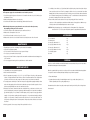
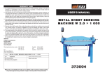
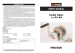
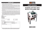
??? CARD
WARRANTY
1. KH Trading machines and tools are covered by 6/24 months warranty, starting on the date of
purchase, as described in the Civil Code (proof of purchase or invoice receipt must be
enclosed with the warranty card when making a claim).
2. This warranty does not cover defects caused by unprofessional handling, machine overloads, not
complying with instructions contained in this manual, using accessories that are not approved,
unauthorized repair, regular wear and tear and damages occurred during transport. Further, this
warranty does not cover parts and accessories such as the motor, carbon brushes, seals and
hot-air operated parts and parts that need to be changed regularly.
3. If the repair is to be found as not covered by the warranty policy, all costs including the repair and shipping to and from the repair centre will be paid by the customer, according to valid price list. See www.
4. When making a claim, you must present the warranty card, showing the date of the purchase, the
serial number of the machine, vendor stamp and signature of sales clerk, as well as the proof of
purchase receipt.
5. Warranty claim shall be made at the vendor shop where you bought your machine or you may mail
it to a service centre. The vendor is obligated to fill out the warranty card (date of sale, serial
number, vendor stamp and signature). All these information must be filled in at the time of sale.
6. The warranty period will be extended for the period of time for which the machine has been in the
service centre possession. If the repair or defect is not covered by the warranty policy, all costs including
the repair and shipping will be paid by the owner of the machine / tool. We recommend sending the
machine in its original packaging. Please, also enclose brief description of the defect with the packaging.
7. Before sending the machine for repair, clean it thoroughly. If the received machine is dirty, it may
be rejected by the service shop or you may be charged a cleaning fee.
USER'S MANUAL
OIL DRAINER
WITH VACUUM
SERVICE
Logistic centre Klecany
Topolová 483
250 67 Klecany
Czech Republic
Claim department phone number: 266 190 156
266 190 111
Fax:
260 190 100
http://www.KHnet.cz
Email: [email protected]
Product:
Type:
OIL DRAINER WITH VACUUM
T2197
Date of manufacture:
T-mobile: 603 414 975
O2:
601 218 255
Vodafone: 608 227 255
Serial number (product series):
Repair centre notes:
Date of sale, stamp, signature:
T2197
Without the correctly filled warranty card or without proof of purchase receipt, including
the product type (invoice, purchase receipt) no warranty claim will be processed.
Dear customer. Thank you for purchasing equipment from KH Trading, s.r.o.
Our company is ready to offer you our services - before, during and after you buy our product.
If you have any question, comment or idea, please contact our business centre. We will do our best to address
your comment or question in timely matter.
Before first use, please read this manual carefully. It is your responsibility to study all instructions,
necessary for safe use and operation and to understand all risks that may be involved during the use
of power machines.
WARNING! Do not try to use this machine before reading this entire manual and before you know
how to handle it. Keep this manual for future reference.
Pay special attention to safety instructions. Not complying with safety rules may cause injury to the
operating person or to people standing by or it may cause damage to the machine or to the work
piece.
Pay special attention to safety notes and safety labels on the machine.
Never remove or damage them.
Please, write information such as the invoice number
and the number of the sale receipt here in this box.
DESCRIPTION
Oil drainer is used during oil changes or vehicle repairs. This new model of oil drainer is equipped with
a special equipment to make oil draining easier from hard to reach areas or if you do not have access to the
oil pan drain plug. The oil may be vacuumed out through the measuring cylinder offering immediate control of
the drained amount. After the spherical valve is closed you may transfer the oil from the reservoir to collection
tanks using compressed air.
The entire equipment is very mobile. Your device was manufactured with modern technology using high
quality components. Drain T2197 offers reliability and long operation life.
TECHNICAL SPECIFICATION
Reservoir volume . . . . . . . . . . . . . . . . . . . . . . . . . . . . . . . . . . . . . . . . . . . . . . . . . . . . . . . . . . . .80 l
The temperature of the vacuumed oil should be between . . . . . . . . . . . . . . . . . . . . . . . .60°C – 100°C
Measuring cylinder volume . . . . . . . . . . . . . . . . . . . . . . . . . . . . . . . . . . . . . . . . . . . . . . . . . . . . .10 l
Recommended inlet pressure . . . . . . . . . . . . . . . . . . . . . . . . . . . . . . . . . . . . . . . . . . . . . . .8 - 10 bar
Suction pressure of the vacuum pump . . . . . . . . . . . . . . . . . . . . . . . . . . . . . . . . . . . . . . . . .- 0.8 bar
Vacuum probes diameter . . . . . . . . . . . . . . . . . . . . . . . . . . . . .6 × 4 mm (flow volume 0.4 - 0.6 l/min)
. . . . . . . . . . . . . . . . . . . . . . . . . . . . . . . . . . . . . . . . . . . . . . . . .6 × 5 mm (flow volume 0.4 - 1 l/min)
. . . . . . . . . . . . . . . . . . . . . . . . . . . . . . . . . . . . . . . . . . . . . . . . .8 × 6 mm (flow volume 1 - 1.6 l/min)
. . . . . . . . . . . . . . . . . . . . . . . . . . . . . . . . . . . . . . . . . . . . . . . . .8 × 7 mm (flow volume 1 - 1.8 l/min)
The accuracy of instructions, graphs and information contained herein, depends on the printing date. Due to
continuous product improvement, the manufacturer reserves the right to change the technical parameters of
the product, without prior customer notification.
2
REPAIR AND MAINTENANCE REPORT
Report and maintenance report:
DATE
REPAIR AND MAINTENANCE REPORT
???
SAFETY INSTRUCTIONS
Symbols used in this manual
SERVICE SHOP
Warning!
This symbol informs you about the risk of personal injury or damage to the machine
or materials.
Use personal safety protection gear.
Do not use open fire around your machine.
Do not smoke during work.
General instructions
• Make sure you know your tool or machine and you are familiar with its operating procedure. Know the
hazards that may occur, if not used correctly.
• If other person is using this machine make sure that he knows how to safely operate this equipment and
that he is familiar with hazards and risk that may occur, if not used correctly.
• Pay special attention to safety notes and safety labels on the machine. Never remove or damage them.
If the warning label becomes unreadable, please contact your vendor.
• Keep your working place clean.
• Never work in tight spaces or in purely lit rooms. Make sure the floor is solid and stable and that you can
move around easily.
• Maintain your tools clean and in safe working conditions.
• Handles must be kept free of grease and dirt.
• Make sure no children, unauthorized persons or animals have access to your workshop.
• Never put your hands or legs inside the working area.
• Never leave your machine / equipment unattended during operation.
• Use only for purposes for which it has been designed.
• Use personal protective gear such as safety goggles, ear protection, respirator, safe working shoes etc.
• Do not overreach, use both hands.
• Never work under the influence of alcohol or other drugs.
• Do not use the machine if you feel dizzy or week.
• Any modifications or improvements to the machine are strictly prohibited. Do not use if you discover
damage, bent part, crack or other condition that may prevent the machine from working properly.
• Never perform any maintenance during operation.
• If you see any unusual sign or hear any strange sound, switch off machine immediately.
• Do not forget to remove all wrenches and screwdrivers from the machine after use.
• Before use, make sure all screws are tightened securely.
• Perform maintenance regularly. Before use make sure the machine is in good working conditions
and without any damage.
• Use only original spare parts during repairs.
• Using non-original spare parts or other parts not approved by the manufacturer may cause damage to the
machine or personal injury to the operating personnel.
• Use this machine only for work that could be handled by it. Do not overload tools, accessories or the
machine. For large work volume use more powerful machine.
• Do not overload. Measure the work load in such way, so it could be done with a comfortable speed.
• Do not expose to extremely high temperature or direct sunlight.
• This machine is not designed for use in humid environments or under water.
3
Assembly
• Do not use the machine unless completely assembled.
Fire prevention instructions
•
Do not leave the oil drainer near heat source.
•
Do not perform any welding jobs on the reservoir.
•
Do not smoke or work with an open fire during work.
•
Use personal protective gear such as gloves, goggles etc.
SCHEMATIC DRAWING T2197
Functional drawing
PART LISTING
1. funnel
2. pressure gauge
3. vacuum generator
4. faucet (1/4")
5. plastic measuring cylinder
6. faucet (1")
7.
suction hose
8. air supply speed-clutch
9. adjusting knob
10. faucet (1/2")
11. oil reservoir
4
???
ASSEMBLY
CAUTION
If the machine breaks down, send it back to the vendor for quick repair.
Please, enclose brief description of the defect. That makes repair easier. If the machine is still covered by
warranty, enclose the warranty card and proof of purchase receipt. After the warranty period expires, we
repair your machine for a special price.
To prevent possible damages during shipping, packed the machine carefully or use the original packaging
material. We are not liable for damages occurred during shipping due to improper packaging.
Note: Pictures and contents in this manual may slightly differ from the actual product or accessories.
It is due to continuous improvement of our products. Such small differences have no effect on the product
functionality.
OPERATION
A. Pumping the engine old oil inside the reservoir
1. Connect the appropriate probe to the suction hose. Push the probe through the oil dipstick opening and
close the suction hose faucet.
2. Open the valve (faucet) that connects the measuring cylinder with the reservoir. Close the valve for oil
draining at the elbow pipe, speed-clutch valve in the upper part of the reservoir and the funnel valve.
3. Connect the vacuum generator to the hose with compressed air and open the valve with compressed air.
The pressure gauge will show value in pressure decrease.
4. When the vacuum reaches minus 0.5 bar, open the valve on the suction hose. The machine will vacuum the
oil from the vehicle engine to the funnel via the suction hose.
B. Pumping the engine oil to the transparent measuring cylinder
1. Connect the appropriate probe to the suction hose. Push the probe through the oil dipstick opening and
close the suction hose faucet.
2. Close the valve (faucet) that connects the measuring cylinder with the reservoir. Close the valve for oil
draining at the elbow pipe, speed-clutch valve in the upper part of the reservoir and the funnel valve.
3. Connect the speed-clutch in the upper part of the measuring cylinder to hose with compressed air and open
the compressed air control valve. The pressure gauge will show value in pressure decrease.
4. When the vacuum reaches minus 0.5 bar, open the valve on the suction hose. The machine will vacuum the
oil from the vehicle engine to the measuring cylinder via the suction hose.
C. Catching the engine oil in the funnel
1. Using jack or lifting equipment, lift the vehicle. Move the funnel under the oil pan plug and unscrew the plug.
2. Open the valve (faucet) that connects the funnel with the reservoir and valve of the speed-clutch on the
upper part of the reservoir. The oil will be transferred from the funnel to the reservoir.
D. Pumping the oil from the measuring cylinder to the reservoir
Open the valve that connects the funnel with the reservoir. The oil will be transferred from the measuring
cylinder to the reservoir.
E. Pumping the old oil out of the reservoir
1. Close all valves except the vacuum generator inlet valve on the measuring cylinder.
NOTE: It is necessary to close the valve between the measuring cylinder and the reservoir. Otherwise the
pressure may damage the measuring cylinder.
2. Place the elbow of the drainage hose in to the used oil collection tank. Make sure the tank is closed
properly to prevent oil leakage.
3. Open the bottom draining valve.
4. Connect the speed-clutch in the upper part of the reservoir to the compressed air hose and open the
compressed air supply valve.
NOTE: If you wish to stop the pumping process immediately, close the air supply valve and pull the ring of
the safety valve. The oil will be transferred out via the draining hose.
NOTE: The air pressure must be increased slowly to:
(1) prevent air losses
(2) speed up the pressure decrease
(3) speed up the oil pumping / transfer
8
5
TROUBLESHOOTING
???
A. The pressure gauge does not show the decrease in the air pressure:
1. Check if the supply (inlet) pressure is between 8 - 10 bar and the air volume is up to 200l/min (for pipes
with diameter of 6 mm).
2. Make sure all applicable valves are closed properly.
3. Check the seal conditions between the measuring cylinder and the oil reservoir.
B. Even though the pressure gauge shows the correct decrease in the air pressure,
the pumping / sucking action does not work.
1. Check the conditions of the seal between the probe and the suction hose.
2. Make sure the oil temperature is not too low.
3. Check if the suction valve on the hose is open. If so, close it.
4. Make sure the suction hose is not blocked or that is not touching the bottom of the oil reservoir.
MAINTENANCE
•
•
•
•
•
Regularly inspect your device for leakage. If you find a leak, fix it immediately.
Inspect the hose tightness regularly.
Do not store the old oil in the reservoir too long to prevent oil decay.
Do not expose your machine to direct sun light.
Keep your tools clean. Dirt from tools may enter the inner machine mechanism and cause damages to the
tools or machine.
• Do not use aggressive cleaning solution or paint thinners to clean the machine.
7. Our findings: Some vehicles (e.g. Toyota Jiamei) has the dipstick opening located in such place that you
cannot push the suction hose in. Even if you manage to slide the hose in, you cannot take it out without
damaging the hose. When you want to pump oil out of a vehicle you never done before, make sure that there
are no obstacles that may prevent you from finishing your job. To avoid the above described problem use
the method of catching the oil from the oil pan to the funnel.
8. Place a net-like, textile acoustic absorber on the cap of the pumping unit. If there is an air in the
compressor or if the operational personnel makes a mistake, water or oil may splash out. Make sure you
solve this problem to avoid incidental injuries due to water or oil spills.
CAUTION: During the pumping process, constantly inspect the oil temperature. If the oil temperature
reaches above 21°C (70F), use personal protective gear and comply with all safety instructions.
ACCESSORIES
1)
2)
3)
4)
5)
6)
7)
8)
user's manual
warranty card
brass pipe, diameter (8 x 7)
nylon pipe (diameter 8 x 6 mm)
brass pipe, diameter (6 x 5)
nylon pipe (diameter 6 x 4 mm)
measuring cylinder
funnel
1 pc
1 pc
1 pc
2 pcs
1 pc
2 pcs
1 pc
1 pc
DISPOSAL
Used oils, as well as other fluids are classified as hazardous waste and must be disposed off in accordance
with valid waste management rules and regulations.
IMPORTANT NOTICE
1. Only qualified person may operate this equipment.
2. Never smoke around the machine.
3. Best oil temperature for pumping is 15.5 - 37.7°C (60-100F). Engine oil viscosity at this temperature
is about 1.3 x higher than that for water. Therefore, oil flow is slower than water flow. If the oil temperature
is lower, the oil flow is lower too and you may not be able to pump it out of the vehicle or transfer it.
4. The output pressure should be plus 10 bar for air compressors equipped with a pumping unit and plus 8 bar
at the end of the pumping unit hose. If the bar is less than 8 bar, you may not be able to pump the oil out or
the flow may be significantly lower, due to the small suction pressure.
5. Besides those two factors, that must be taken into consideration first, you also have to select the correct
probe. For straight probes you may use long brass pipe with flow capacity of 1.8 l per minute or small brass
pipe with flow capacity of 1.4 l per minute. For flexible plastic probes you may chose large pipe with flow
capacity of 1.8 l per minute, medium pipe with flow capacity of 0.6 l per minute and small pipe with flow
capacity of 0.4 l per minute. Oil may be sucked out if the suction hose is 2-3 cm below the oil level. The
hose cannot be touching the bottom or be bent upwards. Oil may not be sucked out if the hose end is above
the oil level.
6. After long operation, it is necessary to inspect if the speed-clutch is not loose.
6
When the operational life of your device is over, dispose off it in accordance with valid rules and regulations.
Your product is made of metal and plastic parts that may be recycled when separated.
1. Disassemble all parts.
2. Separate all parts according to the material they are made of (e.g. metals, rubber, plastics, etc.).
Take the separated parts to the recycling facility near you.
Information about the locations of recycling centres may be found at your local City office or throughout an
Internet search.
7