1
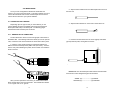
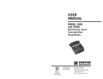
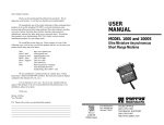
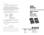
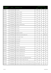
USER
MANUAL
MODEL 1225
ParaLinkTM Parallel
Short Range Modem
Part #07M1225-B
Doc. #104011UB
Revised 9/12/97
CERTIFIED
An ISO-9001
Certified Company
SALES OFFICE
(301) 975-1000
TECHNICAL SUPPORT
(301) 975-1007
http://www.patton.com
1.0 WARRANTY INFORMATION
1.3 SERVICE
Patton Electronics warrants all Model 1225 components to be
free from defects, and will—at our option—repair or replace the product
should it fail within one year from the first date of shipment.
This warranty is limited to defects in workmanship or materials, and
does not cover customer damage, abuse or unauthorized modification.
If this product fails or does not perform as warranted, your sole
recourse shall be repair or replacement as described above. Under no
condition shall Patton Electronics be liable for any damages incurred
by the use of this product. These damages include, but are not limited
to, the following: lost profits, lost savings and incidental or
consequential damages arising from the use of or inability to use this
product. Patton Electronics specifically disclaims all other warranties,
expressed or implied, and the installation or use of this product shall be
deemed an acceptance of these terms by the user.
All warranty and non-warranty repairs must be returned freight
prepaid and insured to Patton Electronics. All returns must have a
Return Materials Authorization number on the outside of the shipping
container. This number may be obtained from Patton Electronics
Technical Service at (301) 975-1007; http://www.patton.com: or,
[email protected].
NOTE: Packages received without an RMA number will not be
accepted.
Patton Electronics' technical staff is also available to answer any
questions that might arise concerning the installation or use of your
Model 1225. Technical Service hours: 8AM to 5PM EST, Monday
through Friday.
1.1 RADIO AND TV INTERFERENCE
The Model 1225 generates and uses radio frequency energy, and if
not installed and used properly—that is, in strict accordance with the
manufacturer's instructions—may cause interference to radio and
television reception. The Model 1225 is designed to provide
reasonable protection from such interference in a commercial
installation. However, there is no guarantee that interference will not
occur in a particular installation. If the Model 1225 does cause
interference to radio or television reception, which can be determined
by disconnecting the Model 1225 from both parallel interfaces, the user
is encouraged to try to correct the interference by one or more of the
following measures: moving the computing equipment away from the
receiver, re-orienting the receiving antenna and/or plugging the
receiving equipment into a different AC outlet (such that the computing
equipment and receiver are on different branches).
1.2 CE NOTICE
The CE symbol on your Patton Electronics equipment indicates
that it is in compliance with the Electromagnetic Compatibility (EMC)
directive and the Low Voltage Directive (LVD) of the Union European
(EU). A Certificate of Compliance is available by contacting Patton
Technical Support.
1
2
2.0 GENERAL INFORMATION
3.0 CONFIGURATION
Thank you for your purchase of this Patton Electronics product.
This product has been thoroughly inspected and tested and is
warranted for One Year parts and labor. If any questions or problems
arise during installation or use of this product, please do not hesitate to
contact Patton Electronics Technical Support at (301) 975-1007.
The Model 1225 is designed to be easy to use. There are no
internal jumpers or DIP switches to set, so there is no need to open the
case to configure the unit (you may need to open the case for wire
connection—refer to Section 4.0).
2.1 FEATURES
•
•
•
•
•
•
•
•
•
The only configuration necessary for operation is proper setting of
the external BUSY / ACKNOWLEDGE switch. The diagram below
shows the location of the BUSY / ACKNOWLEDGE switch on the PC
board, as well as the location of the terminal block.
Extends parallel communication to 2000 feet
Requires no AC power or batteries
Operates over a single twisted pair
Allows devices to communicate in “real time”
Can be configured for BUSY or ACKNOWLEDGE
flow control methods
Compatible with most printer sharing devices
Transmits DC power over the line to compensate for low power
parallel printer interfaces
DB-25 or Centronics parallel connections
RJ-11, RJ-45 or terminal block line connections
Busy
Ack
BUSY/
ACKNOWLEDGE
Switch
G S
Terminal
Block
2.2 DESCRIPTION
The Patton Electronics Model 1225 ParaLinkTM parallel short
range modem allows a PC and a parallel output device (printer, sharing
switch, etc.) to communicate at distances to 2000 feet over a single
unconditioned twisted pair. Supporting parallel data rates to 5 Kbytes
per second (serial rates to 40 Kbps), the Model 1225 derives all
necessary operating power from the parallel interface—no AC power or
batteries are required.
The Model 1225 always works in pairs: A transmitter unit is
plugged into the PC parallel port and a receiver unit is plugged into the
output device parallel port. The connection between them is serial, and
functions at speeds high enough to allow “real time” parallel
communication between the two parallel devices. The Model 1225 has
two unique features that allow it to operate in a wide variety of parallel
applications: First, the Model 1225 transmitter is able to send DC
power down the line to the receiver in order to compensate for low
power parallel printer interfaces. Second, the Model 1225 can be
configured for either BUSY or ACKNOWLEDGE flow control methods.
The Model 1225 receiver is available with either a DB-25 or
Centronics parallel interface (transmitter has DB-25 only). Line
connection options are RJ-11, RJ-45 or terminal block with strain relief.
3
3.1 SETTING THE BUSY / ACKNOWLEDGE SWITCH
For your convenience, the Model 1225 has an externally
accessible BUSY / ACKNOWLEDGE switch (see diagram below). Set
the switch on both transmitter and receiver as follows:
Busy
Ack
1.
The switch must be set the same way on both transmitter and
receiver.
2.
Set the switch to ACKNOWLEDGE on both the transmitter and
reeiver. This should achieve good results in most applications.
3.
If you experience loss of information or other problems with both
switches set to ACKNOWLEDGE, set both switches to BUSY.
4
4.0 INSTALLATION
Once you have configured the Model 1225 transmitter and
receiver, you must connect the system. This section will tell you how to
connect the transmitter and receiver via twisted pair wire and how to
connect the two devices to your system hardware.
2. Strip the outer insulation from the twisted pairs about one inch
from the end.
4.1 CONNECTING THE LINE SIDE
3. Strip back the insulation on each of the 2 wires about .25”.
Depending upon the type of units you have ordered, you can
connect twisted pair wire to the Model 1225 using internal terminal
blocks (with strain relief) or modular jacks. The following pages
describe both kinds of twisted pair connection.
4.1.1 TERMINAL BLOCK CONNECTION
Terminal blocks are used to connect a single pair of bare wires to
the Model 1225. The following instructions will tell you how to open the
case, connect the bare wires and fasten the strain relief collar in place.
4. Insert the two-wire data line to the center (signal) and shield
(ground) terminal posts, then tighten the screws.
1. Open the unit by gently inserting a screwdriver between the
DB-25 connector and the lip of the plastic case (see below). You don't
have to worry about breaking the plastic, but be careful not to bend the
D-sub connector.
G S
NOTE: Make sure the twisted pair cable between the transmitter
and receiver is wired straight through as shown below:
After you have opened the unit's case, you will find the terminal
block mounted at the rear of the PC board. The terminals are labeled
“S” for “signal” and “G” for “ground”.
5
SIGNAL (S)--------------------- (S) SIGNAL
GROUND (G)--------------------- (G) GROUND
6
4. Place the 2 halves of the strain relief assembly on either side of
the telephone wire and press together very lightly. Slide the assembly
so that it is about 2 inches from the terminal posts and press together
firmly.
G S
5. Insert the strain relief assembly and the wire into the slot in the
bottom half of the modem case. Set it into the recess in the case. (If
the telephone wire does not fit into the strain relief assembly, call Patton
Electronics Technical Support at 301-975-1007. We have strain relief
collars to suit a variety of cable diameters.)
6. BEND the top half of the case as necessary to place it over the
strain relief assembly. Do not snap the case together yet.
7. Insert one captive screw through a saddle washer and then
insert the entire piece through the hole in the DB-25 end of the case.
Snap that side of the case closed. Repeat the process for the other
side. This completes the installation process.
4.1.2 RJ-11 & RJ-45 LINE CONNECTION
When using the RJ-11 or RJ-45 modular jacks, install “straight
through” cabling between the transmitter and receiver as shown below:
RJ-11 JACKS
SIGNAL
PIN# COLOR
DATA
GND
3
4
COLOR
Green† --------------Green
Red------------------Red
PIN#
SIGNAL
3
4
DATA
GND
PIN#
SIGNAL
4
5
DATA
GND
RJ-45 JACKS
G S
SIGNAL
PIN# COLOR
DATA
GND
4
5
COLOR
Red† -----------------Red
Green ---------------Green
1 - Blue
2 - Orange
3 - Black
4 - Red
5 - Green
6 - Yellow
7 - Brown
8 - Slate
1 - Blue
2 - Yellow
3 - Green
4 - Red
5 - Black
6 - White
†
7
Standard AT&T color codes—yours may be different
8
APPENDIX A
4.2 CONNECTING TO PARALLEL HARDWARE
PATTON MODEL 1225 SPECIFICATIONS
After connecting the twisted pair line to the Model 1225
transmitter and receiver, you are ready to connect the units to your
parallel hardware. The following steps explain this process:
1.
2.
Plug the DB-25 male connector on the Model 1225 transmitter
directly into the parallel port of the sending device (which is
normally a PC, terminal, host or similar DTE). Note: If you cannot
plug the transmitter directly into the parallel port, use a straight
through DB-25 parallel cable of the shortest possible length. We
recommend 6 feet or less.
The Model 1225 receiver is available with either a DB-25 (male or
female) or 36-pin Centronics (male only) connector. The DB-25
version is designed for direct connection to various print servers
and switches. The Centronics version is designed for direct
connection to the Centronics port of a parallel printer. Note: If you
cannot plug the receiver directly into the port, use a straight
through cable of the shortest possible length. We recommend 6
feet or less.
4.3 OPERATING THE MODEL 1225
Parallel Interface:
Transmitter, DB-25 male; Receiver, DB-25
male or female, 36-pin Centronics male
Power:
Interface powered, no AC power or
batteries needed
Range:
2,000 feet
Transmission:
Half duplex over a single shielded or
unshielded twisted pair (19 - 26 AWG)
Line Interface:
RJ-11, RJ-45 or terminal block with strain
relief
Data Rate:
5 Kbytes per second on parallel interface
(40 Kbps on serial line)
Interface Signals:
Data bits 0-7, ground, Busy or Acknowledge
(externally switch selectable)
Dimensions:
2.67” x 2.10” x 0.74”
Once the transmitter and receiver have been connected to each
other and to their corresponding parallel input and output devices, you
are ready to operate the units. Make sure that the BUSY/ACK switch on
both units are placed on the same setting. Otherwise, the units should
function transparently, just like a cable. There is no ON / OFF switch.
If your Model 1225’s are not operating properly, double-check all of
your connections and try again. If you still experience problems,
change the BUSY / ACKNOWLEDGE setting on both units and try
again. If you still do not obtain satisfactory results, call Patton Technical
Support at (301) 975-1007.
9
10
APPENDIX B
APPENDIX C
PATTON MODEL 1225 BLOCK DIAGRAM
(Transmitter)
PATTON MODEL 1225 PARALLEL PIN CONFIGURATIONS
SOURCE
Common
Common
Common
Common
Common
Common
Common
Common
Printer
TRANSMITTER / RECEIVER (DB-25)
Error (Fault - Active LOW)
DIRECTION
Printer
13- Select (Active HIGH)
12- Paper End (Active HIGH)
11- Busy (Active HIGH)
10- Acknowledge (Active LOW)
9- Data Bit 8 (MSB)
8- Data Bit 7
7- Data Bit 6
6- Data Bit 5
5- Data Bit 4
4- Data Bit 3
3- Data Bit 2
2- Data Bit 1 (LSB)
1- Data Strobe (Active LOW)
Return / Ground -25
Return / Ground -24
Return / Ground -23
Return / Ground -22
Return / Ground -21
Return / Ground -20
Return / Ground -19
Return / Ground -18
RECEIVER (CENTRONICS)
-36
-35
-34
-33
Fault (Active Low) -32
-31
-30
-29
-28
-27
-26
-25
-24
-23
-22
-21
-20
-19
18- (+) 5 Volts
17- Chassis Ground
16- Logic Ground
151413- Select (Active HIGH)
12- Paper End (Active HIGH)
11- Busy (Active HIGH)
10- Acknowledge (Active High)
9- Data Bit 8 (MSB)
8- Data Bit 7
7- Data Bit 6
6- Data Bit 5
5- Data Bit 4
4- Data Bit 3
3- Data Bit 2
2- Data Bit 1 (LSB)
1- Data Strobe (Active LOW)
11
SOURCE
Printer
Printer
Printer
Printer
Computer
Computer
Computer
Computer
Computer
Computer
Computer
Computer
Computer
DIRECTION
Printer
Common
Common
Printer
Printer
Printer
Printer
Computer
Computer
Computer
Computer
Computer
Computer
Computer
Computer
Computer
12
APPENDIX C (continued)
PATTON MODEL 1225 BLOCK DIAGRAM
(Centronics Receiver)
APPENDIX C (continued)
PATTON MODEL 1225 BLOCK DIAGRAM
(DB25 Receiver)
Copyright © 1997
Patton Electronics Company
All Rights Reserved
13
14