1
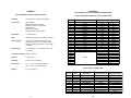
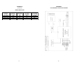
Dear Valued Customer,
Thank you for purchasing Patton Electronics products! We do
appreciate your business. I trust that you find this user manual helpful.
USER
MANUAL
We manufacture one of the widest selections of data
communications products in the world including CSU/DSU's, network
termination units, powered and self-powered short range modems, fiber optic
modems, interface converters, baluns, electronic data switches, data-line surge
protectors, multiplexers, transceivers, hubs, print servers and much more. We
produce these products at our Gaithersburg, MD, USA, facility, and can
custom manufacture products for your unique needs.
MODEL 2026 and
2027
We would like to hear from you. Please contact us in any of the
following ways to tell us how you like this product and how we can meet your
product needs today and in the future.
Web:
Sales E-mail:
Support E-mail:
Phone - Sales
Phone - Support
Fax:
Mail:
Parallel to Serial/
Serial to Parallel
Interface Converters
http://www.patton.com
[email protected]
[email protected]
(301) 975-1000
(301) 975-1007
(301) 869-9293
Patton Electronics Company
7622 Rickenbacker Drive
Gaithersburg, MD 20879 USA
We are committed to a quality product at a quality price. Patton
Electronics is BABT and ISO 9001 certified. We meet and exceed the highest
standards in the industry (CE, UL, etc.).
It is our business to serve you. If you are not satisfied with any
aspect of this product or the service provided from Patton Electronics or its
distributors, please let us know.
Thank you.
Burton A.Patton
Executive Vice President
P.S. Please tell us where you purchased this product.
________________________________________________________
________________________________________________________
________________________________________________________
________________________________________________________
________________________________________________________
________________________________________________________
________________________________________________________
_______
Part #07M2026-D
Doc. #102031UD
Revised 08/17/99
An ISO-9001
Certified Company
SALES OFFICE
(301) 975-1000
TECHNICAL SUPPORT
(301) 975-1007
http://www.patton.com
1.0 WARRANTY INFORMATION
Patton Electronics warrants all Model 2026 and Model 2027
components to be free from defects, and will—at our option—repair or
replace the products should they fail within one year from the first date
of shipment.
This warranty is limited to defects in workmanship or materials,
and does not cover customer damage, abuse or unauthorized
modification. If these products fail or do not perform as warranted, your
sole recourse shall be repair or replacement as described above.
Under no condition shall Patton Electronics be liable for any damages
incurred by the use of these products. These damages include, but are
not limited to, the following: lost profits, lost savings and incidental or
consequential damages arising from the use of or inability to use this
product. Patton Electronics specifically disclaims all other warranties,
expressed or implied, and the installation or use of this product shall be
deemed an acceptance of these terms by the user.
1.3 SERVICE
All warranty and non-warranty repairs must be returned freight
prepaid and insured to Patton Electronics. All returns must have a
Return Materials Authorization number on the outside of the shipping
container. This number may be obtained from Patton Electronics
Technical Support: (301) 975-1007; http://www.patton.com; or,
[email protected].
NOTE: Packages received without an RMA number will not be
accepted.
Patton Electronics' technical staff is also available to answer any
questions that might arise concerning the installation or use of your
Model 2026 or Model 2027. Technical Support hours: 8AM to 5PM
EST, Monday through Friday.
1.1 RADIO AND TV INTERFERENCE
The Model 2026 and Model 2027 generate and use radio
frequency energy, and if not installed and used properly—that is, in
strict accordance with the manufacturer's instructions—may cause
interference to radio and television reception. They have been tested
and found to comply with the limits for Class A computing devices in
accordance with the specifications in Subpart J of Part 15 of FCC rules,
which are designed to provide reasonable protection from such
interference in a commercial installation. However, there is no
guarantee that interference will not occur in a particular installation. If
they do cause interference to radio or television reception, which can
be determined by disconnecting the RS-232 interface, the user is
encouraged to try to correct the interference by one or more of the
following measures: moving the computing equipment away from the
receiver, re-orienting the receiving antenna and/or plugging the
receiving equipment into a different AC outlet (such that the computing
equipment and receiver are on different branches).
1.2 CE NOTICE
The CE symbol on your Patton Electronics equipment indicates
that it is in compliance with the Electromagnetic Compatibility (EMC)
directive and the Low Voltage Directive (LVD) of the Union European
(EU). A Certificate of Compliance is available by contacting Technical
Support.
1
2
2.0 GENERAL INFORMATION
Thank you for your purchase of this Patton Electronics product.
This product has been thoroughly inspected and tested and is
warranted for One Year parts and labor. If any questions or problems
arise during installation or use of this product, please do not hesitate to
contact Patton Electronics Technical Support at (301) 975-1007.
3.0 CONFIGURATION
The Model 2026 and 2027 are simple to install and designed for
excellent reliability. The following instructions will help you set up and
install your converter properly. If you have any questions, please call
Patton Technical Support at (301) 975-1007.
3.1 CONFIGURATION SWITCHES
2.1 FEATURES
• Converts parallel data to serial data or vice versa
• Automatically selects parallel-to-serial or serial-to-parallel operation
• Automatically selects DCE/DTE modes
• Serial data rates to 38,400 bps
• No AC power required
• Supports both software and hardware flow control
• A five-state LED monitors status and diagnostics
• External configuration switches
• Ultra-miniature size
• Made in the USA
The Model 2026 and 2027 each use a set of eight external DIP
switches (see Figure 1) that allow configuration to a wide range of
applications. Because all eight switches are in one externally
accessible DIP switch package, there is no need to open the case for
configuration. The configuration switches allow you to select data
rates, parity, word length and flow control selection. The following
section describes all switch locations, positions and functions.
1 2 3 4 5 6 7 8
OFF
DHS-8
OFF
DHS-8
1 2 3 4 5 6 7 8
2.2 DESCRIPTION
For easy configuration, the Model 2026 and Model 2027 feature a
convenient set of external configuration switches. These accessible
configuration switches allow the user to control baud rate, parity, word
length and flow control. An easy-to-read LED indicator displays status
and operating condition.
Housed in an ultra-miniature ABS plastic case, the Model 2026
comes equipped with a DB-25 female or male connector on the serial
side and a Centronics 36 pin male connector on the parallel side. The
Model 2027 is housed in the same convenient case and comes
equipped with a DB-25 female connector on the serial side and male or
female connector on the parallel side.
Figure 1. The location of the configuration switches:
the Model 2026 (left) and the Model 2027 (right)
The Model 2026 and Model 2027 use a miniature configuration
switch package. To configure your unit, use a small screwdriver and
gently push each switch to its proper setting. The ON and OFF
positions are shown in Figure 2. Default settings for the DIP switches
are shown in the table on the following page. Detailed settings follow
the table.
1 2 3 4 5 6 7 8
DHS-8
The Patton Model 2026 and Model 2027 Parallel to Serial
Converters automatically convert RS-232 serial data to parallel data
format or vice versa. Incorporating advanced microprocessor
technology, they are able to automatically sense and select parallel and
serial modes, as well as DCE/DTE modes. Requiring no AC power, the
Model 2026 and 2027 support serial data rates to 38.4 Kbps.
Configuration
Switches
OFF
Figure 2. The miniature configuration switch package
3
4
DIP SWITCH SUMMARY TABLE
Switch 3 through 5: Data, Parity and Stop Bit
Position
Function
SW1
Flow Control
Factory Default
Hardware
Off
SW2
LED Indicator
On
SW3
Data, Parity, Stop Bits
Off
SW4
Data, Parity, Stop Bits
Off
SW5
Data, Parity, Stop Bits
Off
SW6
Data Rate
Off
SW7
Data Rate
Off
SW8
Data Rate
Off
Enabled
}
}
8B, NP, 1S
9600 bps
3.2 DETAILED SWITCH SETTINGS
Switches 3 through 5 are used to specify the data, parity and stop
bits. The following table shows the settings that may be used:
Data
Parity
Stop
Bit
SW3
SW4
SW5
7B
7B
7B
7B
7B
8B
8B
8B
EP
OP
NP
EP
OP
EP
OP
NP
1S
1S
2S
2S
2S
1S
1S
1S
ON
OFF
ON
OFF
ON
OFF
ON
OFF
ON
ON
OFF
OFF
ON
ON
OFF
OFF
ON
ON
ON
ON
OFF
OFF
OFF
OFF
This section provides detailed information about the function of
each DIP switch and lists all possible settings.
Switches 6 through 8: Frequency and Data Rate
Switch 1: Hardware/Software Control
Switches 6 through 8 determine the frequency and data rate. The
following chart shows the settings that may be used:
The setting for Switch 1 determines whether these interface
converters will control either hardware or software flow control.
Flow Control SW1
Hardware
OFF
Software
ON
Switch 2: Enable/Disable LED Indicator
The setting for Switch 2 determines whether the LED indicator is
enabled or disabled.
LED
Enabled
Disabled
Model 2027
Data Rate
SW6
SW7
SW8
300
600
1200
2400
4800
9600
19200
38400
OFF
ON
ON
OFF
ON
OFF
ON
OFF
OFF
OFF
ON
ON
ON
OFF
OFF
ON
ON
ON
OFF
ON
ON
OFF
OFF
OFF
SW2
ON
OFF
5
6
4.0 INSTALLATION
5.0 OPERATION
The Patton Model 2026 and 2027 are very simple to install. Once
you have configured the DIP switches, just plug your converter in to a
standard cable and you’re ready to go. Figure 3 illustrates the proper
connections for the Model 2026 and 2027. If you have special-ordered
a non-standard connector, your connections may be different.
Once your interface converter is properly configured and installed,
it should operate transparently—as if it were a standard cable
connection. Operating power is derived from the RS-232 data and
control signals; there is no “ON/OFF” switch.
5.1 LED STATUS MONITORS
Model 2026 or 2027
Your cable
The Model 2026 and the Model 2027 feature easy-to-read status
LEDs that glow red to indicate the condition of the transmission line.
Figure 1 shows the location of these LEDs. The following chart
describes the LED’s various functions.
Printer
LED Codes
PC
● ● — ● ——— ● ● — ● ———
Computer is sending data
● ——— ● ——— ● ———
Serial device is connected; computer is
● ● ——— ● ● ———
Both serial and parallel devices are
not sending data
Figure 3. Installing the Model 2026 and 2027
connected; computer not sending
data
● — ● ——— ● — ● ———
Printer not ready, data held in buffer
● ● ● ● ———● ● ● ●
Computer ignoring flow control, data lost
The red LED indicators blink to show data activity. However, since
there is only one indicator on each Model, it uses different LED codes
to demonstrate various messages. The following chart describes these
codes:
Key:
●
Blink
—
Short pause
Long pause
———
7
8
APPENDIX A
APPENDIX B
PATTON MODEL 2026/2027 INTERFACE CONNECTIONS
PATTON MODEL 2026/2027 SPECIFICATIONS
36 PIN CENTRONICS PARALLEL PORT CONNECTIONS
Interface:
Asynchronous., RS-232C compatible
Connectors:
(Model 2026)
Serial: DB-25 male or female;
Parallel: Centronics 36 pin male
(Model 2027)
Serial: DB-25 female;
Parallel: DB-25 male or female
Data Rates:
0 - 38,400 Kbps
LED:
LED displays status and operating condition
Power Supply:
Uses power from RS-232 interface; 9Vdc,
maximum typical current = 20mA; Typical
maximum power consumption = 100mW @
5V (20mA)
Data Format:
7 or 8 data bits; 1 or 2 stop bits; even, odd
or no parity
Temperature Range: 0-60°C (32-140°F)
Altitude:
0-10,000 feet
Humidity:
5 to 95% non-condensing
Dimensions:
3.37” x 1.26” x 0.76” (Model 2026);
3.15” x 1.26” x .76” (Model 2027)
Weight:
Pin
1
2
3
4
5
6
7
8
9
10
11
12
13
14
15
16
17
18
19
20
21
22
23
24
25
Description
Direction
Serial to Parallel
Strobe
Output
Data Bit 0
Output
Data Bit 1
Output
Data Bit 2
Output
Data Bit 3
Output
Data Bit 4
Output
Data Bit 5
Output
Data Bit 6
Output
Data Bit 7
Output
Acknowledge
Input
Busy
Input
Paper End (to ground through resistor)
Input
Select
Input
To +5V through resistor
Error
Input
To +5V through resistor
To +5V through resistor
Output
Ground
Note: All other pins are unconnected
DB-25 PORT CONNECTIONS
2 oz. (56.8 grams)
Pin #
1
2
3
4
5
6
7
8
9
20
Signal
Name
FG
TD
RD
RTS
CTS
DSR
SG
CD
V+
DTR
Connected to DTE
Description
Frame Ground
Transmit Data
Input & Power Source
Receive Data
Output
Request to Send
Input & Power Source
Clear to Send
Output
Data Set Ready
Output
Signal Ground
Carrier Detect
Output
External Power Source
Input for Power
Data Terminal Ready Input & Power Source
Note: All other pins are unconnected
9
Parallel to Serial
Input
Input
Input
Input
Input
Input
Input
Input
Input
Output
Output
Output
Output
10
Connected to DCE
Output
Input & Power Source
Output
Input & Power Source
Input & Power Source
Input & Power Source
Input for Power
Output
APPENDIX B
(continued)
APPENDIX C
PATTON MODEL 2026 BLOCK DIAGRAM
SIGNAL DIRECTIONS
Converter
Function
Serial to Parallel
Serial to Parallel
Parallel to Serial
Parallel to Serial
Serial Port
Connected
DTE
DCE
DTE
DCE
Serial Data
Flow
TD
RD
RD
TD
11
Serial Software Flow Serial Hardware
Ctrl. Signal
Flow Ctrl Signal
(XON/XOFF)
(DTR, CTS, DSR)
RD
CTS, DSR
TD
DTR
TD
DTR
RD
CTS, DSR
12
APPENDIX D
PATTON MODEL 2027 BLOCK DIAGRAM
Copyright ©
Patton Electronics Company
All Rights Reserved
13