1
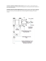
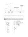
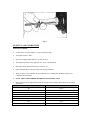
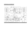
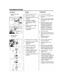
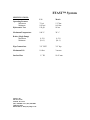
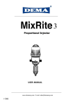
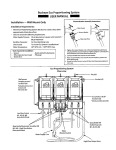
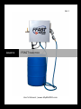
2012
ADAPCO
FFAST INJECTOR
User’s Manual | www.MyADAPCO.com
SAFETY INSTRUCTIONS
When using chemical Injection pumps, basic safety
precautions should always be followed to reduce risk of fire,
electric shock, and personal injury. Failure to follow these
instructions could result in death or serious injury.
READ ALL INSTRUCTIONS
GENERAL SAFETY CONSIDERATIONS
•
Always wear protective clothing including gloves and safety goggles when working on or near
chemical injection pumps.
•
Inspect tubing regularly when replenishing chemical solution for cracking, swelling, or
deterioration and replace as necessary. (Always wear protective clothing and safety glasses
when inspecting tubing.)
•
Follow directions and warnings provided with the chemicals from the chemical manufacturer.
•
Secure chemicals and Injection pumps, making them inaccessible to children and pets.
•
Make sure the voltage on the Injection pump stand matches the voltage at the installation.
•
Do not cut plug off electrical cord or the ground lug – consult a licensed electrician for proper
installation.
•
Injection pump is NOT to be used to handle flammable liquids.
SAFETY OPERATING PROCEDURES
•
All Injection pumps are tested with water before shipment.
•
Finger tighten plastic connections. DO NOT USE A WRENCH.
•
Before repair or moving Injection pump, disconnect power cord or turn off power to stand. Depressurize system and drain chemical. (Always wear protective clothing and safety glasses
when working on Injection pump.)
•
Always consult licensed plumber and electrician before installation and make sure to conform to
local codes.
•
Be sure to de-pressurize system prior to hook-up or disconnection of Injection pump.
•
DO NOT MODIFY pump as this poses a potentially dangerous situation and voids the warranty.
•
For accurate volume output, pump must be calibrated under all operating conditions.
TABLE OF CONTENTS
SAFETY INSTRUCTIONS..............................................................................................1
INTRODUCTION ............................................................................................................3
INSTALLATION LOCATION ........................................................................................3
INSTALLATION RECOMMENDATIONS ....................................................................3
START-UP AND OPERATION ......................................................................................5
GENERAL MAINTENANCE..........................................................................................8
PARTS DIAGRAM ..........................................................................................................9
TROUBLESHOOTING GUIDE ....................................................................................10
RATIO ADJUSTMENTS ...............................................................................................11
SPECIFICATIONS .........................................................................................................12
WARRANTY .....................................................................................................................
INTRODUCTION
These installation, operation and maintenance instructions cover your FFAST System™ chemical Injection
pump.
This model is designed to inject liquid or completely dissolved solutions that are recommended and
approved for injection into water and applied to a variety of applications. Water treatment chemicals can
also be applied.
It is the responsibility of the operator to determine the correct dosage settings of the unit using the chemical
manufacturer recommendation for dispensing their product, and assure that proper dosage is being
maintained.
INSTALLATION LOCATION
MOUNTING OPTIONS: Your new chemical injection system will come with (2) heavy duty carabineer
hooks. Two holes are predrilled on the top flange of the mounting base, carabineers can be inserted into the
predrilled holes and used to hang chemical injector from a chain linked fence or similar mounting surface
approximately six feet above the ground level.
ALTERNATIVE MOUNTING OPTION: If carabineer hooks are not suitable for mounting surfaces
available at your facility, your chemical injection system also comes with (4) 5/16 x 18 SS bolts and (4) zip
toggles for flat mounting surfaces.
Locate anywhere on a cold water line that is free of sand and grit. The installation of a filter with a 140mesh screen is highly recommended in the front of the unit, especially if sand or grit is present in the water
source.
Safety Precautions
Label all water lines, valves and connections with a WARNING that the water supply contains additive. If
the solution that is being injected is not suitable for drinking water, all water lines should be labeled:
WARNING NOT FOR HUMAN CONSUMPTION!
AVOID A POTENTIALLY HAZARDOUS CHEMICAL ACCIDENT, a location should be selected to
provide a safe but accessible place for the chemical solution container. It should be kept away from
children and/or high usage areas and the location must also not be susceptible to freezing temperatures.
AVOID SOLUTION CONTAMINATION, use only clean, filtered water. Dirt, debris and other
contaminants in the solution container can cause excessive wear to the unit.
INSTALLATION RECOMMENDATIONS
The unit can be installed directly into the water line using the connections provided with the unit. Check
for water leaks after the water has been turned on and the desired water pressure has been attained.
NOTE: IF OPERATING PRESSURE EXCEEDS MAXIMUM LIMIT, INSTALL A PRESSURE
REGULATING VALVE.
CONNECT NOZZLE ASSEMBLY HOSE: Install nozzle hose to injector. Take precautions not to
cross-thread while tightening. If hose guard is slowing progress, remove guard and continue installation of
hose assembly them replace.
CONNECT SOLUTION CONTAINER: Install hose kit onto unit. Option 1: install quick coupling onto
the end of the hose kit. Secure the coupling to the container of the approved solution. Option 2: Install the
foot valve to the end of the suction tubing. Insert the suction tubing into the opening in the solution
container.
INSTALL A BACK FLOW PREVENTOR: AN APPROVED BACK FLOW PREVENTOR MUST BE
INSTALLED in the water line ahead of the unit to prevent water and chemical mixture from entering the
source water supply. This is because the chemicals that are being injected may not be suitable for human
consumption.
SHUT-OFF VALVE: Installed on the injection unit already, is a series of valves that control the flow of
both water and mixed solution. Always control the unit using the nozzle valve on the exiting water line.
IMPORTANT: Using the inlet side valve could cause full strength solution to siphon into the feed line.
Fig. 1
START-UP AND CALIBRATION
GETTING STARTED
1.
Connect power cord to available 115 volts 50/60 Hertz outlet
2.
Turn panel switch to “OFF” .
3.
Open water supply manual ball valve (yellow in color)
4.
Turn manual 2 position 3-way ellipsoid valve to the vertical position
5.
Dial Piston Stroke adjustment knob to a setting of “10”
6.
Depress Dispensing Nozzle and let flow into an empty container.
7.
Allow the water to flow until the chemical solution (or water during the calibration process), has
completely primed all lines.
8.
NOTE: THE SYSTEM PRESSURE SHOULD NOT EXCEED 75 PSI
9.
Move the Piston Stroke adjustment knob to the desired mix ratio setting determined from the dosing
chart below.
Pump Setting
10
9
8
7
6
5
4.5
4
Mix Ratio
1.5:1
2:1
3:1
4:1
5:1
6:1
7.5:1
9:1
10. NOTE: DOSING CHART PROVIDED FOR REFERENCE PURPOSES ONLY, IN ORDER
TO ASSURE DESIRED MIX RATIO HAS BEEN ACHIEVED, CALIBRATION IS
REQUIRED.
CALIBRATION
11. You will need (1) 5 gallon and (1)10 gallon graduated container. Fill the 5 gallon graduated container
with chemical (or water for calibration purposes).
*Flow meter installed behind the dispensing nozzle can also be used to measure effluent by
resetting meter to “0” before each test and reading output recorded.
12. Place suction line into 5 gallon graduated container.
13. Depress dispensing nozzle and allow mixture to flow into empty 10 gallon catch container, continue
depressing nozzle until exactly (1) gallon of material is siphoned from the 5 gallon container.
14. Release dispensing nozzle and measure the volume of mixture collected in the 10 gallon container (i.e.
if (6) total gallons is collected in the catch container mix ratio is equivalent to a 5:1 mix ratio)
15. Adjust Piston Stroke adjustment knob and repeat steps 11-14 until desired mix ratio is achieved.
16. Once mix ratio is achieved, tighten Piston Stroke Adjustment set knob.
NORMAL OPERATION
Because certain chemical solutions separate over time, a re-circulation pump is needed to re-suspend the
solution before being injected to achieve optimum results.
1.
Turn manual 2 position 3-way ellipsoid valve to the horizontal position.
2.
Turn Panel switch to “RE-CIRCULATE”
3.
Allow the pump to run for approximately 3 to 4 minutes per 30 gallons. Run time is proportionate to
the amount of solution remaining in the container.
4.
Turn the Panel switch back to left position “OFF”
5.
Turn Manual 3-way ellipsoid valve to Vertical Position.
6.
Insert dispensing nozzle into tank and begin to fill. NOTE: If full tank is desired, nozzle WILL NOT
shut of automatically. Please be cognizant of the fluid level in your chemical tank. Do NOT leave the
injection system unattended while filling chemical tank.
7.
After tank filling is complete, hang nozzle on cover using built in hook and close water supply manual
ball valve.
GENERAL MAINTENANCE
The unit has been designed and built to inject liquid solutions with a minimum of maintenance. However,
solution being pumped by the unit will leave deposits, residue and precipitates that require attention to
provide maximum dependable service. The degree to which these contaminants accumulate depends on the
solutions being pumped and the water supply.
RINSE INJECTOR AFTER EACH USE:
Put suction tube into a 1 qt. or more container of fresh water and operate injector by running
sufficient amounts of water through injector to rinse and free contaminants from the lower end of
the pump. Contaminants allowed to remain in the injector can dry out and foul or damage lower end
at the next start up. This procedure is not required for continuous or daily operation.
CLEAN SOLUTION CONTAINER:
For open containers, keep covered to prevent dirt, flies, feathers and other flying debris from entering the
container. Sealed returnable/refillable drums are recommended.
STORAGE:
Do not allow unit to be subjected to freezing temperatures. Regularly check fasteners used to vertically
secure pump mount plate. Replace pump cover after recirculation, concentration adjustments, and after
each use. The pump cover is designed to protect dosing components from damage due to an impact from a
foreign object as well as protection from UV rays.
PARTS DIAGRAM – EXPLODED VIEW
CHANGING FEED RATE
The Feed Rate on the FFAST System injector is infinitely adjustable EVEN WHILE OPERATING AND
UNDER WATER PRESSURE. To change feed rates:
1.
Loosen Piston Stroke set knob.
2.
Turn Piston Stroke adjustment knob clockwise to increase concentration of mixture and turn counterclockwise to decrease concentration of mixture.
3.
Never operate pump with setting below “4”.
4.
Once desired dosing rate is achieved, retighten Piston Stroke set knob.
NOTE: Do not screw Ratio Adjuster below “4” on the graduated sleeve. Check outlet water to assure
desired feed rate is being delivered.
FFAST™ System
SPECIFICATIONS:
U.S.
Metric
Operating Pressure
Maximum
Minimum
Hydrostatic Test
75 psi
10.0 psi
150 psi
5.17 bar
0.69 bar
10 bar
Maximum Temperature
100° F
38° C
Ratios (Single Pump)
Maximum
Minimum
(1.5:1)
(10:1)
(1.5:1)
(10:1)
Pipe Connections
3/4” GHT
3/4” bsp
Maximum Lift
10 foot
3 meters
Suction Hose
¾ ” ID
19.05 mm
Adapco, Inc.
550 Aero Lane
Sanford, FL 32771
(407) 330-4800 / Fax (407) 330-9888
1-800-367-0659
Email address: [email protected]