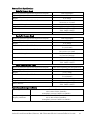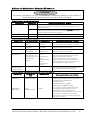
1
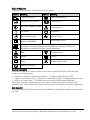
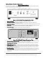
USER MANUAL TriLux SINGLE CHIP CAMERA ©2007 by IsoLux® llc - All rights reserved. This publication is protected by copyright. Copying, disclosure to others or other use of this publication is prohibited without express written consent of IsoLux llc. IsoLux llc reserves the right to make changes shown herein without notice or obligation. Contact IsoLux llc or your representative for the latest information. Important general instructions for use CAUTION Ensure that this product is only used as intended and described in the instruction manual, by adequately trained and qualified personnel and that maintenance and repair is only carried out by authorized technicians. CAUTION Operate this product only in the combinations and with the accessories and spare parts listed in the instruction manual. Use other combinations, accessories and wearing parts only if they are expressly intended for this use and if the performance and safety requirements are met. WARNING Reprocess the products before every application and before returning them for repairs as required by the instruction manual in order to protect the patient, user or third parties. CAUTION Federal law (USA) restricts this device to sale by or on the order of a physician. IsoLux IIc 100 Ferncroft Road, Danvers, MA USA 01923 PH 978.774.9136 FAX 978.774.1559 2 Contents Table of Symbols.................................................................................................................... 4 Product Description............................................................................................................... 4 How Supplied................................................................................................................... 4 Indications ....................................................................................................................... 5 Contraindications ............................................................................................................ 5 Components ..................................................................................................................... 5 Combinations ................................................................................................................... 5 Patient environment ....................................................................................................... 6 Notes on Safety...................................................................................................................... 6 Labeling, Displays, Controls and Connections .................................................................... 7 Setup .................................................................................................................................... 10 Before the Procedure Begins......................................................................................... 10 When the Procedure Begins.......................................................................................... 11 Performing White Balance ....................................................................................... 12 After the Procedure Ends.............................................................................................. 12 Maintenance and Cleaning ................................................................................................. 12 Maintenance ........................................................................................................................ 12 Maintenance intervals .................................................................................................. 12 Cleaning of Controller & IsoVu Camera Head .................................................................. 12 Reprocessing the EndoVu & CardioVu Camera Head ................................................ 13 Sterilization and High-Level Disinfection.................................................................... 13 Steris® Sterilization ................................................................................................. 14 Sterrad® Sterilization............................................................................................... 14 High-Level Disinfection ............................................................................................ 14 Troubleshooting................................................................................................................... 15 Fuse Replacement ......................................................................................................... 16 Disposal of the product, packing material and accessories......................................... 16 Warranty and Service ................................................................................................... 16 Repairs and Returns ..................................................................................................... 17 Parts List ............................................................................................................................. 18 Technical Data..................................................................................................................... 18 Camera Controller Specifications ................................................................................. 18 Controller Interfaces ..................................................................................................... 18 Camera Head Specifications ......................................................................................... 19 Operating and storage conditions................................................................................. 19 Guidance and Manufacturer’s Declaration EN 60601-1-2 .......................................... 20 IsoLux IIc 100 Ferncroft Road, Danvers, MA USA 01923 PH 978.774.9136 FAX 978.774.1559 3 Table of Symbols Following are the various symbols shown on the camera. Symbol Meaning Symbol Meaning Camera Connector Type CF Equipment Automatic Gain Control Camera Select Auto White Balance (AWB) Attention: Consult accompanying documentation. On (Power) Off (Power) Date of Manufacture Remote Control CE marking according to Directive 93/42/EEC ~ Alternating Current A Registered trademark of Intertek Testing Services NA, Inc., a nationally Recognized Testing Laboratory, listing compliance as Medical Electrical Equipment to standard UL and Canadian Standards. Fuse Equipotentiality Output S-Video Video Caution: High Voltage Protective Ground Product Description The TriLux Single Chip camera consists of the camera controller which handles multiple camera head configurations – EndoVu is a Camera V-Mount thread with a ½” Charge Coupled Device (CCD). CardioVu is a Camera with ¼” CCD with a 50mm field of view at a 60mm working distance. IsoVu is a Camera with ¼” CCD that attaches to Surgical Fiber Optic Headlight. The camera controller supplies power to the camera, controls the electronic shutter and automatic gain, and transmits the camera’s video signal to the monitor, and other peripherals. How Supplied The TriLux Single Chip Controller and Camera Head(s) is supplied non-sterile and is designed for reuse. IsoLux IIc 100 Ferncroft Road, Danvers, MA USA 01923 PH 978.774.9136 FAX 978.774.1559 4 Indications EndoVu camera is for use during diagnostic and/or surgical procedures when endoscopic video assistance is required. CardioVu camera is for with recording video with the camera head mounted on the retractor in an open surgical procedure. IsoVu camera is for with recording video with the camera head mounted on the surgeon’s head in an open surgical procedure. WARNING When implemented for therapeutic applications, a second equivalent camera should be available, in the event that the primary camera stops working. WARNING Operators who are not trained and qualified to perform endoscopic procedures should not use this device. Contraindications None known Components 05-001/05-001P TriLux Camera Controller contains: (1) Camera Controller, (1) Power Cord (NTSC only), (1) S-video cable, (1) User Manual 05-002/05-002P CardioVu contains: (1) Camera Head 05-003/05-003P EndoVu contains: (1) Camera Head 05-004/05-004P IsoVu contains: (1) Camera Head Please contact Customer Service or local distributor at the phone number listed on the back of this manual if any of the above components are missing. Combinations IMPORTANT All the equipment connected to this unit shall be certified according to Standard IEC60601-1, IEC60950, IEC60065 or other IEC/ISO Standards applicable to the equipment. Persons combining products to form a system are responsible for not impairing the system’s compliance with the performance and safety requirements, and that the technical data and intended use are adequately fulfilled according to Standard IEC 60601-1-1. Do not connect item(s), which are not specified as part of the system. The equipment or system should not be adjacent to or stacked with other equipment and that if adjacent or stacked use is necessary, the equipment or system should be observed to verify normal operation in the configuration in which it will be used. Do not touch connecting devices for electrical connections between the different components (such as signal input and output connections for video signals, data exchange, control circuits, etc.) and the patient at the same time. Portable and Mobile RF communications equipment can affect Medical Electrical Equipment. The use of accessories, transducers and/or cables other than those specified may result in increased emissions or decreased immunity of the equipment or system. Medical Electrical Equipment needs special precautions regarding EMC and needs to be installed and put into service according to the EMC information provided in this manual. IsoLux IIc 100 Ferncroft Road, Danvers, MA USA 01923 PH 978.774.9136 FAX 978.774.1559 5 Patient environment The TriLux Single Chip camera NTSC/PAL is patient equipment and can be used in the patient environment. Notes on Safety This User Manual contains procedures for inspecting, preparing, operating, maintaining, and storing this device. This manual does not describe how to perform actual procedures or teach proper surgical techniques. Following are some important safety notes for operating this device: • This User Manual must be available to the medical team during every procedure. WARNING Always exercise safety precautions when using electrical equipment to prevent operator and patient shock, fire hazard, or equipment damage. WARNING When Endoscopes are used with energized endoscopically used accessory, the patient leakage current may be additive. CAUTION To reduce the risk of fire and electric shock, do not expose electrical equipment to moisture. When cleaning, do not immerse any electrical device in liquid, unless manufacturer’s instructions indicate otherwise. • Do not use or store liquids on or above this device. IsoLux IIc 100 Ferncroft Road, Danvers, MA USA 01923 PH 978.774.9136 FAX 978.774.1559 6 Labeling, Displays, Controls and Connections TriLux Camera Controller Following are the displays, controls, and connections located on the front and back of the camera controller and the camera heads. Figure 1: 05-001/05-001P TriLux Controller Front View 1. Main Power Switch – Controls the main power to activate the camera. 2. White Balance Button – Performs an “Automatic White Balance” procedure, making color adjustments for the current lighting situation. 3. Camera Select Button – Provides unique setting for the EndoVu, CardioVu & IsoVu camera heads. 4. Gain Button – Turns Automatic Gain Control (AGC) Low, High, and Off. When AGC is on in low light situations, the gain rises to increase contrast and resulting brightness. 5. Camera Receptacle – Insert the camera head connector key facing up. Figure 2: 05-001/05-001P TriLux Controller Rear View 6. Equipotentiality bonding connection – Connect to an equipotential bonding strip if intracardial operations are being performed (IEC 601-1-1/EN 60601-1-1 standards). 7. Video (Composite) Connectors – Used for the output of a composite video signal to compatible equipment. 8. S-Video (Y/C) Connectors – Used for the output of an S-Video signal to compatible equipment. 9. Remote Connector – Accepts a remote cable to provide a signal to remotely operate a compatible video accessory (VCR or printer) via the camera head button. Cable must be connected to the appropriate receptacle on the device. 10. Identification Plate - Identifies the serial number and catalog/model number of the Controller. 11. Power Entry Module – Used to supply AC power to the unit. Integrated line filter helps filter out unwanted noise and voltage spikes associated with the input voltage. Also, houses the fuse compartment. IsoLux IIc 100 Ferncroft Road, Danvers, MA USA 01923 PH 978.774.9136 FAX 978.774.1559 7 Camera Heads Figure 3: 05-003/05-003P EndoVu Camera Head 1. 2. 3. 4. 5. SN – Serial number of the camera head. REF – Identifies the catalog/model number of the camera head. Standard Screw V-mount thread - Attachment to an Endoscope Coupler/Lens. Black Remote Button – Press to initiate a remote accessory device. Camera Connector Soaking Cap – Protects connector during reprocessing. Figure 4: 05-002/05-002P CardioVu Camera Head 1. 2. 3. 4. 5. 6. SN – Serial number of the camera head. REF – Identifies the catalog/model number of the camera head. Camera Head – CCD & Optical Lens. Light Guide/Cable Post – Attachment for fiber optics light guide/cable. Camera Connector Soaking Cap – Protects connector during reprocessing. Intermediate Box – Houses internal electronics and provides for interconnects. IsoLux IIc 100 Ferncroft Road, Danvers, MA USA 01923 PH 978.774.9136 FAX 978.774.1559 8 Figure 5: 05-004/05-004P IsoVu Camera Head 1. Camera Head - CCD & Optical lens. 2. Camera Connector– Connects to the controller. Figure 6: Connected devices NOTE The diagram above is an illustrative example only. Consult with the facility manager for instructions on connecting to your video equipment and network. NOTE When recording a video and printing a video print, you must use the same type of cable (either BNC or S-Video) to transmit the video signal from the Controller along the video chain to the end VCR or print device. NOTE The last device of each video chain must always terminate with 75 Ohm (75 Ohm “ON”). The devices inside the video chain must be switched to high impedance (75 Ohm “OFF”). IsoLux IIc 100 Ferncroft Road, Danvers, MA USA 01923 PH 978.774.9136 FAX 978.774.1559 9 Setup WARNING EQUIPMENT not suitable for use in presence of a FLAMMABLE ANESTHETIC MIXTURE WITH AIR OR OXYGEN OR NITROUS OXIDE WARNING Remove power cord from the rear of the unit to disconnect from the mains supply. CAUTION Check that the mains/line voltage is the same as the voltage specified on the identification plate. CAUTION GROUNDING RELIABILITY CAN ONLY BE ACHIEVED WHEN THE EQUIPMENT IS CONNECTED TO AN EQUIVALENT RECEPTACLE MARKED HOSPITAL ONLY OR HOSPITAL GRADE. WARNING An additional multiple portable socket-outlet or extension cords shall not be connected to the system. WARNING If High Frequency (HF) Electro surgical instruments are used, keep the working element always within the field of view to prevent accidental burns. Always ensure a sufficient distance from the tip of the Endoscope with conductive accessories before activating the HF output. Only medical electrical equipment that complies with IEC 60601-1 is to be used with this product. WARNING If High Frequency (HF) endoscopically-used accessories are used, avoid safety hazard associated with gas concentrations. Before the Procedure Begins Perform these setup steps before the procedure begins: 1. Sterilize the EndoVu & CardioVu camera heads and endoscope that you plan to use for the procedure according to parameters specified in the related user manuals. CAUTION IsoVu is not intended to be sterilized. 2. Thoroughly dry the components before assembling them. Make sure all optical surfaces are free of streaks. 3. Switch on the camera, monitor, and lightsource. • For this purpose follow the corresponding manuals for each device. 4. Press the Camera Select button to correspond to the camera head being engaged. IsoLux IIc 100 Ferncroft Road, Danvers, MA USA 01923 PH 978.774.9136 FAX 978.774.1559 10 NOTE The GAIN is automatically OFF when the Controller is turned on. For maximum camera performance, turn GAIN ON. When the Procedure Begins EndoVu perform these steps: 1. Surgical scrub threads on an optical coupler into camera head and inserts the scope into the optical coupler eyepiece. 2. The surgical scrub attaches the light guide to the light post on the scope. 3. The surgical scrub ensures that the cable connector is clean and dry. Using sterile technique, the surgical scrub hands off the cable connector to the non-sterile circulator. 4. The circulator inserts the cable connector into the receptacle on the front of the camera unit. Note that the red dot on the two halves of the connector will align when the connectors are proper oriented. 5. The surgical scrub and circulator perform the “White Balance” procedure (see Performing White Balance, below). CardioVu perform these steps: 1. The surgical scrub attaches the light guide to the light post on the camera head intermediate box. 2. The surgical scrub mounts the camera head to the retractor or clipped to patient drape. CAUTION The CardioVu camera is not intended to come in direct contact with patient tissue. 3. The surgical scrub ensures that the cable connector is clean and dry. Using sterile technique, the surgical scrub hands off the cable connector to the non-sterile circulator. 4. The circulator inserts the cable connector into the receptacle on the front of the camera unit. Note that the red dot on the two halves of the connector will align when the connectors are proper oriented. 5. The surgical scrub and circulator perform the “White Balance” procedure (see Performing White Balance, below). IsoVu perform these steps: 1. Attach the camera head onto the surgeons head light. 2. Ensure that the cable connector is clean and dry. 3. Inserts the cable connector into the receptacle on the front of the camera unit. Note that the red dot on the two halves of the connector will align when the connectors are proper oriented. 4. Perform the “White Balance” procedure (see Performing White Balance, below). The Controller is set up and the camera is ready to use. CAUTION High intensity light may damage the camera head. WARNING Remove the camera before defibrillating the patient. IsoLux IIc 100 Ferncroft Road, Danvers, MA USA 01923 PH 978.774.9136 FAX 978.774.1559 11 Performing White Balance Follow these steps to perform a White Balance procedure: 1. The operating room circulator adjusts the light source to the mid-to-maximum range. For more information on the light source, refer to your Light Source User Manual. 2. An individual in the surgical field points the scope at a clean white surface. 3. The circulator presses the White Balance button while the scope remains focused on the white surface. “White balance ok” should be displayed on your monitor and an audible beep will sound. After the Procedure Ends After the procedure, the camera head may be disconnected, cleaned and stored if desired. See below for cleaning instructions for the camera. To disconnect the camera head from the controller, grasp the ridged metallic portion of the connector immediately adjacent to the controller and gently pull it away from the camera controller. CAUTION Hold the TriLux camera controller in place while pulling the connector of the camera head. CAUTION If the connector is grasped anywhere other than the ridged metallic portion adjacent to the TriLux controller, it will lock in place and cannot be removed. Do not pull on the flexible cable portion of the device or the cable could be damaged. Be sure to grasp the connector as noted above. Maintenance and Cleaning Maintenance CAUTION This product has no user serviceable parts. Do not remove the cover or attempt to do any repairs yourself. IMPORTANT In your inquiries or correspondence please always indicate the model and serial number printed on the identification plate. Further documentation is available from the manufacturer on request. Maintenance intervals IMPORTANT To prevent incidents caused by aging and wear, the device and its accessories must be serviced at adequate intervals. Depending on the frequency of use, however at least once a year, an expert must check the device and carry out a safety test. Cleaning of TriLux Controller & IsoVu Camera Head Clean the TriLux controller, IsoVu camera head and video cables using a soft cloth dampened with 70% isopropyl alcohol. Remove stains by using a mild ammonia-based cleaner. IsoLux IIc 100 Ferncroft Road, Danvers, MA USA 01923 PH 978.774.9136 FAX 978.774.1559 12 WARNING Make sure that no moisture enters the device: danger of electric shock. Before reprocessing, turn the controller switch off and disconnect the power cord from the rear of the controller. IMPORTANT Do not use any cleaning or scouring agents or solvents on the device. Reprocessing the EndoVu & CardioVu Camera Head The EndoVu & CardioVu camera heads are designed to undergo routine cleaning and sterilization. For maximum performance and camera life, clean and sterilize this device according to your institutional guidelines and within the parameters specified in this section. Always clean the camera immediately after use. Thoroughly remove bioburden prior to disinfecting or sterilizing the camera. WARNING Do not use ultrasonic for reprocessing the camera head. Do not autoclave this camera head as damage will occur and warranty will be voided. CAUTION Camera Head cannot withstand temperature above 60°C (140°F). IMPORTANT Always check to ensure that the soak cap for the camera cable is firmly seated into place prior to any reprocessing. Follow these steps to clean the EndoVu & CardioVu camera heads: 1. Disconnect the cable connector from the controller. 2. Inspect the camera housing and cable for cuts, tears, cracks, or other defects. 3. Disassemble the optical coupler, scope and light guide from the camera. 4. Firmly seat the soaking cap onto the camera head connector. 5. Rinse with distilled or de-mineralized water, then wipe and dry external surfaces thoroughly. 6. Remove the camera cable soak cap, and ensure the controller contacts are dry. The contacts must be completely dry before engaging with the connector on the controller. 7. If the coupler window has fingerprints or smudges, clean it with a cotton tip applicator and 70% isopropyl alcohol. Sterilization and High-Level Disinfection Prior to sterilization, devices must be thoroughly cleaned and dried. The camera must be sterile before you use it on a patient. NOTE Use a biological indicator to confirm effective sterilization after each procedure. IsoLux IIc 100 Ferncroft Road, Danvers, MA USA 01923 PH 978.774.9136 FAX 978.774.1559 13 Steris® Sterilization The components of the EndoVu & CardioVu Camera Head are materially compatible with the Steris process. Follow the manufacturer’s instructions. A Steris System 1® Processor was used to validate the use of this method. Sterrad® Sterilization The components of the EndoVu & CardioVu Camera Head are materially compatible with the Sterrad process. Follow the manufacturer’s instructions. High-Level Disinfection Material compatibility was verified using a 2.4% Gluteraldehyde solution, with an immersion time of 45 minutes. Users must validate their own conditions to assure disinfection. Follow the disinfectant’s manufacturer instructions. Use proper safety attire such as gloves, protective eyewear, and a facemask, according to your institutional guidelines. Make sure your working area is well ventilated. To perform a high-level disinfection: 1. Perform a thorough cleaning. 2. Firmly seat the soaking cap onto the camera head connector. 3. Immerse the entire camera head, including the cable connector, in the disinfectant solution. Refer to your institutional and the disinfectant’s manufacturer guidelines regarding the concentration of the solution and recommended soaking time. 4. Rinse with distilled or de-mineralized water, then wipe and dry external surfaces thoroughly. Remove the camera cable soak cap, and ensure the TriLux controller contacts are dry. The contacts must be completely dry before engaging with the connector on the TriLux controller. IsoLux IIc 100 Ferncroft Road, Danvers, MA USA 01923 PH 978.774.9136 FAX 978.774.1559 14 Troubleshooting IMPORTANT If you can not clear errors using this table, please inform the Service Department or send in the device for repair. Do not attempt to do any repairs yourself. Problem Potential Cause Intervention All power switches are turned on. None of the green lights for the power switches illuminate. Unit may not be plugged into wall outlet Turn all component power switches off. Then plug unit into wall outlet. TriLux Controller fuse may be blown. Change the TriLux controller fuse. See Changing the TriLux Controller Fuse Section. TriLux Controller may be faulty Contact your local representative. Video cable wiring from TriLux controller to the monitor may be incorrect or connections may be faulty. Check that wiring is correct and that connections are secure. You may need to disconnect and reconnect cables. See Labeling, Displays, Controls and Connections Section. Video cables from the controller to monitor may be defective. Try new video cables. Monitor may be faulty. Refer to Monitor User Manual. Debris on tip of endoscope. Clean tip of endoscope with sterile gauze and 70% isopropyl alcohol. Fog on scope. Warm scope in warm water bath or use anti-fog agents. All components are turned on. Image is not displayed on the monitor. Image is fuzzy or unclear. Moisture is on cable connector. Dry the camera connector with gauze before reinserting into the TriLux controller. Black and white image on video monitor. Defective S-Video cable. Change S-Video cable between TriLux controller and monitor. Intermittent electrical interference on video image that coincides with application of electrocautery. Electrosurgical generator Connect the power cords for the unit and electrosurgical generator to separate outlets. Colors are distorted. Lighting may have changed. Auto white balance the camera again. Image is too dark on monitor. AGC is off. Turn AGC on. Light source intensity too low. Increase intensity. Refer to the Light Source User Manual. Light guide is defective. Disconnect light guide and inspect light output by shining the light guide against a solid surface. Intensity should be bright and homogeneous. Refer to the Light Source User Manual. Light fibers in scope defective. Put light source on standby. Angle scope away from direct view and inspect lighted fibers. Look for dark areas that indicate broken fibers. Refer to your scope user manual. Defective camera cable. Return camera head with cable for repair. Image interference when camera cable is moved. Ensure that the cables are not crisscrossed. IsoLux IIc 100 Ferncroft Road, Danvers, MA USA 01923 PH 978.774.9136 FAX 978.774.1559 15 Fuse Replacement CAUTION The specification of the fuses in the device must correspond with the fuse rating on the identification plate. To replace the fuse: 1. Turn the TriLux controller power switch off. 2. Disconnect the power cord from the rear of the TriLux controller. 3. Use the tip of a screwdriver or ballpoint pen to push up the catch to release the fuse holder. Fuses Catch for Release 4. Remove the blown fuses and install new ones. IMPORTANT Use T 0.4A L/250V fuses. 5. Reinstall the fuse holder. The catch must audibly click. Disposal of the product, packing material and accessories For disposal, observe the relevant regulations and laws valid in your country. • For further information please contact the manufacturer. Warranty and Service The warranty as set forth herein is exclusive and in lieu of all other warranties, express or implied, remedies, obligations, and liabilities, merchantability and fitness for use and of consequential damages. The products are being sold only for the purposes described herein and such warranty runs only to the customer. In no event shall IsoLux llc be liable for any breach of warranty in any amount exceeding the purchase price of the product. The IsoLux llc Single Chip Camera is covered by the warranty by the original purchaser for a period of one year beginning from the date of shipment. It is warranted against defects in materials and defects that occur under normal utilization. The warranty is void if the system has been misused, abused, improperly installed or operated. Should the medical equipment described become inoperable within the period of usage specified for the applicable equipment due to a defect in material or workmanship, IsoLux llc will, at its sole option, either repair or replace the applicable equipment at no charge. IsoLux llc reserves the right to make design changes on its product without liability to incorporate said change in IsoLux llc products previously designed or sold. IsoLux IIc 100 Ferncroft Road, Danvers, MA USA 01923 PH 978.774.9136 FAX 978.774.1559 16 Work performed on IsoLux llc products by anyone other than IsoLux llc or an authorized representative will void any and all warranties. Carefully inspect the product upon receipt. If you discover a defect, notify IsoLux llc or your local distributor immediately. Repairs and Returns Contact IsoLux llc Customer Service or your local distributor at the address shown on the back page of this User Manual before returning a product for credit, exchange, warranty repair, or non-warranty service repair. 1. Provide the following information: • The product model and serial number • The reason the product requires repair • The hospital purchase order number 2. You will receive a Return Goods Authorization (RGA) tracking number for the returning product, which must be displayed on the return outer packaging. IMPORTANT IsoLux llc or its authorized representative reserves the right to refuse and/or return merchandise, for which an RGA number has not been obtained or properly displayed on the outer packaging. 3. All shipping and insurance charges must be prepaid. Sender is responsible for any loss or damage during shipment. 4. Clean and sterilize (if applicable) all returned goods. 5. Pack the product in the original or comparable shipping carton. Clearly write the RGA number on the outside of the shipping carton along with the shipping address. A restocking charge may be issued for all customer returns unless there was a shipping error. No credit will be issued for the return if the product is damaged or opened. For repairs, upon receipt of the product, IsoLux llc, or its authorized representative, will determine if the product is covered under warranty. In the event the product is not covered under warranty or violates the warranty, the sender will be notified with an estimated cost for repair. The product will not be repaired until it has been authorized with a written purchase order. IsoLux llc Systems, Inc., or its authorized representative, is responsible for shipment of the repaired device back to the sender. IsoLux IIc 100 Ferncroft Road, Danvers, MA USA 01923 PH 978.774.9136 FAX 978.774.1559 17 Parts List Component NTSC PAL TriLux Camera Controller 05-001 05-001P CardioVu Camera Head 05-002 05-002P EndoVu Camera Head 05-003 05-003P IsoVu Camera Head Light 05-004 05-004P 32mm V-Mount Optical Coupler 05-003-1 Remote Connection Cables for VCR and printer See your representative Technical Data TriLux Camera Controller Specifications Electromagnetic Compatibility (EMC) in acc. With EN / IEC 60601-1-2 High Frequency Surgical Equipment 390 kHz 9000V p-p maximum Type of Applied part CF Protection class in accordance with EN / IEC 60601-1; (UL 60601-1 / CSA C22.2 No. 601.1 – for USA / Canada) Degree of protection against foreign solids Class I IP20 ≥ 0.49” ( ≥12.5 mm) diameter Mode of operation / duty factor Continuous operation Not Category AP or Category APG Equipment Degree of protection when flammable gases are present Weight: 8.0 Lbs. (3.63 Kg) Dimensions W x H x D: 12.60” x 3.98” x 14.32” (320 x 101 x 364 mm) Power 100-240 V~, 50/60 Hz, 35 VA TV system NTSC: 525 lines, 30 frames, 2:1 Interlace PAL: 625 lines, 25 frames, 2:1 Interlace Horizontal resolution > 480 TV lines at center (luminance channel) Signal-to-noise ratio > 44 dB @ luminance channel TriLux Controller Interfaces Video Outputs S Video (Mini DIN 4-pin) Video (BNC) Remote Outputs NTSC output level PAL output level 2x Y: 1.0 Vp-p / 75 Ohm 2x C: 0.286 Vp-p / 75 Ohm 2x Y: 1.0 Vp-p / 75 Ohm 2x C: 0.3 Vp-p / 75 Ohm 2x 1.0 Vp-p / 75 Ohm composite RCA Phono Jack <10Ω between tip and ring at closure + polarity on tip; <50V, <100mA IsoLux IIc 100 Ferncroft Road, Danvers, MA USA 01923 PH 978.774.9136 FAX 978.774.1559 18 Camera Head Specifications EndoVu Camera Head Degree of protection against the ingression of liquids Type of Applied part IPX7 (watertight) CF Weight Dimensions Camera Head W x H x D: 9 oz. (255g) Ø 0.90” x 1.15” x 2.05” (22.9 x 29.2 x 52.1mm) 10’ (3.0m) ½” format color CCD NTSC: 768(H) x 494(V) PAL: 752(H) x 582(V) 3 Lux @ F1.4, +6dB Camera Cable length Image Sensor Pixels, effective Sensitivity CardioVu Camera Head Degree of protection against the ingression of liquids Type of Applied part IPX7 (watertight) CF Weight Dimensions Camera Head W x D: 9 oz. (255g) Ø 0.32” x 1.38” (8.1 x 35.1mm) 1.1” x 1.6 x 3.2” (27.9 x 38.1 x 82. 3mm) 22” (0.6m) to Intermediate box, 10’ (3.0m) to Circular Connector Dimensions Intermediate Box W x H x D: Camera Cable length Image Sensor ¼” format color CCD Pixels, effective NTSC: 768(H) x 494(V) PAL: 752(H) x 582(V) IsoVu Camera Head Light Degree of protection against the ingression of liquids Type of Applied part Weight Dimensions Camera Head W x D: Camera Cable length Image Sensor Pixels, effective IP60 (Dust-tight)/Liquid (Non-protected) BF 3.5 oz. (100g) Ø 0.31” x 2.23” (7.9 x 56.6mm) 12’ (3.7m) 1/4” format color CCD NTSC: 768(H) x 494(V) PAL: 752(H) x 582(V) Operating and storage conditions Operating Conditions Storage, transport and shipping conditions 32°F to 113°F (0°C to 45°C) 30% to 90% relative humidity, atmospheric pressure 700hPa to 1060hPa -4°F to 140°F (-20°C to 60°C) 10% to 90% relative humidity, atmospheric pressure 700hPa to 1060hPa IsoLux IIc 100 Ferncroft Road, Danvers, MA USA 01923 PH 978.774.9136 FAX 978.774.1559 19 Guidance and Manufacturer’s Declaration EN 60601-1-2 IMPORTANT The Camera is intended for use in the electromagnetic environment specified below. The customer or user of this device should ensure that it is used in such an environment. Table 201 Emission - All Equipment and Systems Emissions Test Compliance RF Emissions CISPR 11 Electromagnetic Environment - Guidance Group 1 The Camera uses RF energy only for its internal function. Therefore, its RF emissions are very low and are not likely to cause any interference in nearby electronic equipment. Class A The Camera is suitable for use in all establishments, other than domestic, and those directly connected to the public low-voltage power supply network that supplies buildings used for domestic purposes. Harmonics IEC 61000-3-2 Class A 120 VAC AC Mains Flicker IEC 61000-3-3 Complies 120 VAC AC Mains Table 202 Immunity - All Equipment and Systems Immunity Test IEC 60601 Test Level Compliance Level Electromagnetic Environment - Guidance ESD IEC 61000-4-2 ±6kV Contact ±8kV Air ±6kV Contact ±8kV Air Floors should be wood, concrete or ceramic tile. If floors are synthetic, the r/h should be at least 30%. EFT IEC 61000-4-4 ±2kV Mains ±1kV I/Os ±2kV Mains ±1kV I/Os Mains power quality should be that of a typical commercial or hospital environment. Surge IEC 61000-4-5 ±1kV Differential ±2kV Common ±1kV Differential ±2kV Common Mains power quality should be that of a typical commercial or hospital environment. Voltage Dips/Dropout IEC 61000-4-11 >95% Dip for 0.5 cycle >60% Dip for 5 cycles >30% Dip for 25 cycles >95% Dip for 5 seconds >95% Dip for 0.5 cycle >60% Dip for 5 cycles >30% Dip for 25 cycles >95% Dip for 5 seconds Mains power quality should be that of a typical commercial or hospital environment. If the user of the Camera requires continued operation during power mains interruptions, it is recommended that the unit be powered from an uninterruptible power supply or battery. Power Frequency 50/60Hz Magnetic Field IEC 61000-4-8 3A/m 3A/m Power frequency magnetic fields should be that of a typical commercial or hospital environment. Table 204 Emissions - Equipment and Systems that are NOT Life-supporting Immunity Test IEC 60601 Test Level Compliance Level Conducted RF IEC 61000-4-6 3 Vrms 150 kHz to 80 MHz V1= 3Vrms Radiated RF IEC 61000-4-3 3 V/m 80 MHz to 2.5 GHz E1=3V/m Electromagnetic Environment - Guidance Portable and mobile communications equipment should be separated from the Camera by no less than the distance calculated/listed below: D=(3.5/V1)(Sqrt P) D=(3.5/E1)(Sqrt P) 80 to 800 MHz D=(7/E1)(Sqrt P) 800 MHz to 2.5 GHz where P is the max power in watts and D is the recommended separation distance in meters. Field strengths from fixed transmitters, as determined by an electromagnetic site survey, should be less than the compliance levels (V1 and E1) Interference may occur in the vicinity of equipment containing a transmitter. IsoLux IIc 100 Ferncroft Road, Danvers, MA USA 01923 PH 978.774.9136 FAX 978.774.1559 20 IMPORTANT The Camera is intended for use in the electromagnetic environment in which radiated disturbances are controlled. The customer or user of this device can help prevent electromagnetic interference by maintaining a minimum distance between portable and mobile RF Communication Equipment and the Camera as recommended below, according to the maximum output power of the communication equipment. Table 206 Recommend Separation Distances between portable and mobile RF Communications equipment and the Camera Equipment and Systems that are NOT Life-supporting Max Output Power (Watts) Separations(m) 150 kHz to 80 MHz D=1.667 (Sqrt P) Separations(m) 80 kHz to 800 MHz D=1.667 (Sqrt P) Separations(m) 800 MHz to 2.5 GHz D=2.3333 (Sqrt P) 0.01 0.11667 0.11667 0.23333 0.1 0.36894 0.36894 0.73785 1 1.1667 1.1667 2.3333 10 3.6894 3.6894 7.3785 100 11.667 11.667 23.333 Specifications are subject to change without notice. Manufactured in the U.S.A. IsoLux IIc 100 Ferncroft Road, Danvers, MA USA 01923 PH 978.774.9136 FAX 978.774.1559 21 Distributed by: IsoLux llc ® 100 Ferncroft Road Danvers, MA 01923 USA Tel: 978-774-9136 Fax: 978-774-1559 J02944-119 Rev. B Manufactured by: Vision System Group A Division of Viking Systems, Inc. 134 Flanders Road Westborough, MA 01581 USA EU Authorized Representative: Medical Device & QA Services 76 Stockport Road Timperley, Cheshire WA15 7SN United Kingdom