1
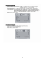
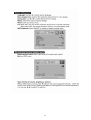
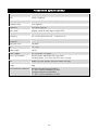
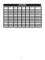
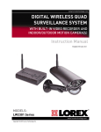
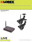
1
Thank you for purchasing the Lorex L22LT11B Touch Screen Monitor.
This manual refers to the following products:
•
L22LT11B Touch Screen Monitor
Please visit us on the web for the most current Manuals, Quick Start Guides and Firmware.
Additional Language Manuals may also be available at:
www.lorextechnology.com
CAUTION
RISK OF ELECTRIC SHOCK
DO NOT OPEN
CAUTION: TO REDUCE THE RISK OF ELECTRIC SHOCK
DO NOT REMOVE COVER (OR BACK).
NO USER SERVICABLE PARTS INSIDE.
REFER SERVICING TO QUALIFIED SERVICE PERSONNEL.
The lightning flash with arrowhead symbol, within an
equilateral triangle, is intended to alert the user to the
presence of uninsulated “dangerous voltage” within the
products ‘ enclosure that may be of sufficient magnitude
to constitute a risk of electric shock
The exclamation point within an equilateral triangle is
intended to alert the user to the presence of important
operating and maintenance (servicing) instructions in
the literature accompanying the appliance.
WARNING: TO PREVENT FIRE OR SHOCK HAZARD, DO NOT EXPOSE
THIS UNIT TO RAIN OR MOISTURE.
CAUTION: TO PREVENT ELECTRIC SHOCK, MATCH WIDE BLADE OF
THE PLUG TO THE WIDE SLOT AND FULLY INSERT.
2
B E F O R E Y O U S TA R T
THIS PRODUCT MAY REQUIRE PROFESSIONAL INSTALLATION
LOREX IS COMMITTED TO FULFILLING YOUR SECURITY NEEDS
• We have developed user friendly products and documentation.
Please read the Quick Start Guide and User Manual before you
install this product.
• Consumer Guides and Video Tutorials are available on our web
site at www.lorextechnology.com/support
• If you require further installation assistance, please visit
www.lorextechnology.com/installation or contact a
professional installer.
• Please refer to the “Need Help” insert for technical support and
customer care information.
• Please note that once the components of this product have been
unsealed, you cannot return this product directly to the store
without the original packaging.
May 5 2011 - R5
AVANT DE
COMMENCER
ANTES DE
EMPEZAR
CE PRODUIT POURRAIT EXIGER UNE
INSTALLATION PROFESSIONNELLE
ESTE PRODUCTO PUEDE EXIGIR UNA
INSTALACIÓN PROFESIONAL
LOREX S’ENGAGE À SATISFAIRE
VOS BESOINS SÉCURITAIRES
LOREX SE COMPROMETE A SATISFACER
SUS NECESIDADES EN SEGURIDAD
• Veuillez lire le guide de démarrage rapide et le
mode d’emploi avant d’installer ce produit
• Favor de leer la guía de instalación rápida y la
guía del usuario antes de instalar este product.
• Les guides du consommateur et les séances de tutorat vidéo sont disponibles sur l’Internet en visitant
www.lorextechnology.com/support
• Puede conseguir las guías del consumidor y los
cursos en enseñanza video sobre el Internet visitando www.lorexcctv.com/support
• Si vous avez besoin de l’aide pour l’installation,
veuillez visiter www.lorextechnology.com/installation ou contactez un spécialiste en installation
• Si necesita ayuda para la instalación, visite
www.lorextechnology.com/installation o contacte
un especialista en instalaciones
• Veuillez référer à l’insert “Need Help” pour
ob¬tenir de l’information sur le service à la clientèle
et le support technique
• Favor de referir al documento “Need Help” para
obtener información acerca del servicio al cliente y
al soporte técnico
• Veuillez constater qu’une fois que les
com¬posantes de ce produit ont été retirées de
l’emballage, vous ne pourrez plus retourner ce
produit directement au magasi
• Favor de notar que una vez que los componentes
de este producto han sido removidos del embalaje,
no podrá devolver este producto directamente a la
tienda
www.lorextechnology.com
VIEW YOUR WORLD™
VOIR VOTRE MONDEMD
VER SUMUNDO™
ALWAYS AWARE™
TOUJOURS AU COURANTMD
SIEMPRE CONSCIENTE™
May 5 2011 - R5
Need Help?
CONTACT US F I R S T
DO NOT RETURN THIS PRODUCT TO THE STORE
Please make sure to register your product at www.lorextechnology.com
to receive product updates and information
3 Easy Ways to Contact Us:
Online:
Product Support is available 24/7 including product
information, user manuals, quick start up guides and FAQ’s at
www.lorextechnology.com/support
To order accessories, visit
www.lorextechnology.com
By Email:
Technical Support (for technical/installation issues)
[email protected]
Customer Care (for warranty and accessory sales)
[email protected]
Customer Feedback
[email protected]
By Phone:
North America:
Customer Service: 1-888-425-6739 (1-888-42-LOREX)
Tech Support: 1-877-755-6739 (1-877-75-LOREX)
Mexico: 1-800-514-6739
International: +800-425-6739-0
(Example: From the UK, dial 00 instead of +)
Ma y 5 2011 - R11
VIEW YOUR WORLD™
VOIR VOTRE MONDEMD
VER SUMUNDO™
ALWAYS AWARE™
TOUJOURS AU COURANTMD
SIEMPRE CONSCIENTE™
Necesita Ayuda
COMUNÍQUESE PRIMERO
CON NOSOTROS
SIMPLY AWARE™
SIMPLEMENT AU COURANTMD
SIMPLEMENTE CONSCIENTE™
Vous Avez Besoin
D’aide?
CONTACTEZ-NOUS
D’ABORD
NO DEVUELVA ESTE PRODUCTO A LA TIENDA
NE RETOURNEZ PAS CE PRODUIT AU MAGASIN
Cerciórese de por favor colocar su producto en www.
lorexcctv.com/registration para recibir actualizaciones y la información del producto
Veuillez veiller à enregistrer votre produit à www.lorexcctv.com/registration pour recevoir des mises à jour et
l’information de produit
3
3
maneras sencillas de comunicarse con
nosotros:
façons faciles de nous contacter:
En línea:
En ligne:
apoyo al producto disponible 24/7 incluyendo información
del producto, manuales para el usuario, guías de inicio
rápido y preguntas más frecuentes en
www.lorextechnology.com/support
le support des produits est disponible 24 heures sur 24, 7
jours sur 7, y compris les informations sur les produits, les
guides de l’utilisateur, les guides de démarrage rapide et les
foires à questions
Para colocar pedidos de accesorios, visite
Pour commander des accessoires, visitez
www.lorextechnology.com
www.lorextechnology.com/support
www.lorextechnology.com
Por Correo Electrónico:
Par Courriel:
soporte técnico (para asuntos técnicos/la instalación)
support technique (pour les questions techniques et ’installation) [email protected]
servicio al cliente (respecto a la garantía y a la venta
de accesorios)
service à la clientèle (pour les questions de garantie
et les ventes d’accessoires)
Comentarios de cliente
Commentaires des clients
Por Teléfono:
Par Téléphone:
Norte América:
Atención al cliente: 1-888-425-6739 (1-888-42-LOREX)
Soporte técnico: 1-877-755-6739 (1-877-75-LOREX)
L’Amérique du Nord:
Service à la clientèle: 1-888-425-6739 (1-888-42-LOREX)
Support technique: 1-877-755-6739 (1-877-75-LOREX)
Mexico: 1-800-514-6739
Mexico: 1-800-514-6739
Internacional: +800-425-6739-0
International: +800-425-6739-0
(Ejemplo: Desde el Reino Unido, marque el 00 en lugar del +)
(Exemple: À partir du Royaume-Uni, composez 00 au lieu de +)
[email protected]
O
[email protected]
[email protected]
OU
[email protected]
[email protected]
Ma y 5 2011 - R11
Table of Contents
System components and accessories.................................................................................. 4
Connection instructions ....................................................................................................... 5
Packaging procedures .................................................................................................................. 5
Adjusting the viewing angle .......................................................................................................... 5
Connection instructions ................................................................................................................ 6
Using the display................................................................................................................... 7
Turning on the display................................................................................................................... 7
Function controls .......................................................................................................................... 7
OSD selection ........................................................................................................................ 9
OSD Menu ..................................................................................................................................... 9
Troubleshooting .................................................................................................................. 12
Production Specifications................................................................................................... 13
Preset Modes ...................................................................................................................... 15
Appendix .............................................................................................................................. 16
Connector pin assignment .......................................................................................................... 16
3
System components and accessories
LCD display
Signal cable (VGA)
Power cord
Audio cable
USB cable
DVI cable
Quick Start Guide
Quick Start
Guide
Note: Please keep the original carton and packing materials for future transportation or shipment of
the display.
4
Connection instructions
Packaging procedures
If you need to package the display again, please keep the original carton and packing materials.
The procedures for re-packaging the display are as follows:
1. Unplug the power cord from the display (make sure all attached peripherals are already
turned off).
2. Put the display into the carton in the original packaging manner.
Important
Before you start, place a clean towel or cloth on a flat surface, where you can place the removed
display panel without being damaged.
Adjusting the viewing angle
You may adjust the display's viewing angle from -5° ~ 20°.
(Figure 2)
Note:
• When you adjust the viewing angle of the display, avoid touching the LCD display with your fingers,
as this may damage or break the liquid crystal screen.
• When you adjust the angle of your display, pay attention to your adjustment action, as shown in the
figure above.
5
Connection instructions
CAUTION: Before installation, please make sure to power off the display and the computer or
DVR (Digital Video Recorder).
Back of PC or DVR
1
Power cord
2
VGA cable
or
DVI Cable
3
Audio cable
4
USB cable
Connect one end of the power cord into the AC power connector on
the rear of the display, and the other end to an electrical wall outlet.
Connect the signal cable:
- For analog operation use the VGA cable. Connect the VGA
signal cable to the VGA connector on the rear of the PC or DVR.
- For digital operation use the DVI-D cable. Connect the DVI-D
signal cable to the DVI connector on the rear of the monitor
and the other end to the DVI connector on the rear of the PC or
DVR. This is recommended for optimal performance.
Connector one end of the audio cable to the audio-in connector on
the rear of the display, and the other end of the cable to the
audio-out jack on the PC (PC only)
Connect one end of the USB cable to the USB connector on the
display, and the other end of the USB cable to the PC or DVR. This is
required for touch screen operation on your PC or DVR.
Warning:
1. Please verify the videocard you are using and use an appropriate signal cable.
2. Pay attention to the PIN assignments and connection directions. Do not force to avoid bending
the pins.
VGA (D-sub 15 pin)
6
Using the display
Turning on the display
Turn on the display before turning on the computer. When the power is on, the LED on the power
button lights blue and the screen image will appear after about 10 seconds. If the LED doesn't
light blue or no image appears, please verify if the display is properly connected.
(Figure 4)
Function controls
1
POWER
Power Switch
2
LED
Power Indicator
3
MENU
4
AUTO
5
>
6
<
OSD function
menu
Auto adjustment
button
Right/increase
button
Left/decrease
button
Power ON/OFF
Blue LED - Power ON mode
Orange LED - Power saving mode
When the monitor is under normal working condition,the
indicator will light green (or blue);if the monitor is under
power saving mode ,the indicator will glow red (or
orange)or off, And the indicator will turn off under the
power off mode.
OSD off: Displays the OSD function menu
OSD on: Confirm the OSD function option
OSD off: Perform the auto adjustment function
OSD on: Exit the OSD function menu
OSD on: Press this button to select/increase the
adjustment
OSD off: Press this button directly to serve as the
shortcut for input
OSD on: Press this button to select/decrease the
adjustment
Control of the Touch Function
Note:
1. Before using the touch function, make sure you connect the USB cable from
the monitor into the USB port on the computer or DVR. The touch applications
from the CD-ROM must be installed if you are running Windows XP and VISTA.
2. When the touch function is active, make sure there are no obstructions on the
screen.
(Figure 5) Ensure there are no foreign objects that may come
in contact with the display.
The touch function may replace the mouse after you start the
Windows operating system and introduce appropriate finger
gesture judgement.
7
This monitor is optimized to work with LOREX Edge+ DVR series for Touch Screen navigation
capabilities.
There is no need to install drivers as the DVR will auto detect the monitor. A USB cable must be
connected between the DVR and the monitor for the touch screen feature to work. If you plan to use
the monitor’s touch screen capabilities with a PC, install the drivers located on the CD.
Finger gesture and related Windows software applications are listed below:
Windows 7
Windows Vista
Windows XP
Tablet
Windows XP
Drag
Click
Y
Y
Y
Y
Y
Y
Y
Y
Double-click
Y
Y
Y
Y
Single-touch
digitizer
Y
Y
Y
N
Multi-touch
gestures
Y
N
N
N
Finger Operation
Use your finger for touch applications.
Note:
• Keep the display away from any heat sources such as electric radiators, natural gas pipes or
direct sunlight.
Also keep the display away from excessive dust, mechanical vibration or shock.
• Retain the original carton & packaging materials. They will be convenient for you, if you need to
transport your display again.
• For the best protection, pack the display in the original manner of package from the factory.
• To maintain a brand new appearance of the display, clean with soft cloth regularly. Please
remove stubborn stains with a soft cleaner rather than strong cleaners such as diluting agent,
benzene or corrosive cleaner as they may damage the display. For the sake of safety, remove
the power plug prior to cleaning.
• The touch function may need about 7 seconds to resume if the USB cable is re-plugged or the
computer resumes from sleep mode (suspend mode).
8
OSD selection
Press the Menu button on the monitor to activate the OSD function, continue pressing the Menu
button to select an option from the 7 functions in the menu. Select the function you want to adjust on
the OSD function menu and then press MENU to make the adjustment. Please use the <or> button
to adjust the screen to your desired status. After finishing the setting, press AUTO to exit the OSD
screen.
OSD Menu
9
10
11
Troubleshooting
Problems
Possible solutions
Power LED doesn't light up.
• Check if the power switch is in the ON position
• Make sure the power cord is properly connected
No screen image
•
•
•
•
Abnormal colors are present
• Please refer to the "Color Temperature" section to adjust the
RGB color or select a color temperature.
The image bounces or a wave
pattern is present
• Remove any electrical device that may be causing electrical
interference.
• Check the signal cable and make sure the pins are not bent.
The screen image is not
centered or the size is incorrect
• Press the Auto button to automatically optimize the display
status.
• Refer to the "Image Control section".
Check if the power switch is in the ON position
Make sure the power cord is properly connected
Make sure the signal cable is securely connected
When the display is in use, it will automatically turn off to enter
the power saving mode. Please press any key to see if the
image resumes.
Note: Never disassemble or repair the product yourself. If your problem cannot be solved
according to the troubleshooting guidelines, please contact your local dealer.
12
Production Specifications
LCD panel size
21.5in (54.61 cm)
DCR
10000:1 (typical)
Viewing angle
Horizontal 170°, vertical 160° (typical)
Response time
5 ms (typical)
Brightness
265 cd/m (typical)
Input signal
Analog signal (D-sub); digital signal (DVI)
Display color
16.7 M colors
Frequency
24 ~ 83 kHz Horizontal, 50 ~ 76 Hz Vertical
Optimum graphic
resolution
Max Pixel clock
1920 x 1080(60Hz)
180 MHZ
Tilt
-5° ~ 20°
Audio output
1W X 2
Power supply
AC: 100-240V ~ 50-60Hz;
Power consumption
Size
Display mode: Max 48W; LED color: Blue
Sleeping mode: Less than 1W, LED color: Orange
Width: 507 mm, Height: 402 mm, Depth: 200 mm
Weight
5Kg
Environmental conditions
Operating temperature/humidity:
5 ~ 35°C, relative humidity: 10-85%
Storage temperature/humidity:
5 ~ 35°C, relative humidity: 10-85%
2
13
Touch Screen Specifications
14
Preset Modes
Preset
Pixel
Horz
Freq
(kHz)
Horz
Polarity
Vert
Freq
(Hz)
Vert
Polarity
Pixel Clk
(MHz)
Source
1
640 x 480
31.469
-
59.940
-
25.175
VGA
2
720 x 400
31.469
-
70.087
+
28.322
VGA
3
800 x 600
37.879
+
60.317
+
40.000
VESA
4
1024 x 768
48.363
-
60.004
-
65.000
VESA
5
1280 x 720
45.00
+
60.00
+
74.25
6
1280 x 960
60.00
±
60.00
±
108.000
VESA
7
1280 x 1024
63.98
+
60.02
+
108.000
VESA
8
1440 x 900
55.94
-
59.89
+
106.500
CVT 1.30MA
9
1600 x 1200
75.00
+
60.00
+
162.000
VESA
10
1680 x 1050
65.29
-
60.0
+
146.25
CVT 1.76MA
11
1920 x 1080
67.5
+
60.00
+
148.5
15
VESA/CEA-861D
VESA/CEA-861D
Appendix
Connector pin assignment
• 15 pin color display signal cable:
PIN No.
Description
PIN No.
Description
1.
Red
9.
+5V
2.
Green
10.
Logic ground
3.
Blue
11.
Monitor ground
4.
Monitor ground
12.
DDC-serial data
5.
DDC-return
13.
H-sync
6.
R-ground
14.
V-sync
7.
G-ground
15.
DDC-serial time sequence
8.
B-ground
24 pin DVD-D display signal cable:
Pin No.
1
2
3
4
5
6
7
8
9
10
11
12
Description
TMDS Data 2 TMDS Data 2 +
TMDS Data 2 / 4 Shield
TMDS Data 4 TMDS Data 4 +
DDC Clock
DDC Data
No Connect
TMDS Data 1 TMDS Data 1 +
TMDS Data 1 / 3 Shield
TMDS Data 3 -
Pin No.
13
14
15
16
17
18
19
20
21
22
23
24
16
Description
TMDS Data 3 +
+3.3/+5V Power (from PC)
Ground (Return for +5V)
Hot Plug Detect
TMDS Data 0 TMDS Data 0 +
TMDS Data 0 / 5 Shield
TMDS Data 5 TMDS Data 5 +
TMDS Clock Shield
TMDS Clock +
TMDS Clock -
Enhance your security with genuine Lorex products and accessories.
Order whatever you need at www.lorextechnology.com
or call 1-888-42-LOREX (1-888-425-6739)
Special offer Coupon: MLLLLDCG-CM-OOJICORN
Parking Lot
Office
LBC6050
Home
LNZ4001
LDC6050
Drive Way
CVC6950B
PROTECT EVERYTHING
THAT MATTERS
Add wired or wireless cameras to expand the
“Envelope of Protection” for your business,
your home and your family
LW2702
Convenience Store
LW2110
May 9 2011 - R14
Restaurant
Front Door
LW2301
Nursery
LW2003
Home Office
LW2902
Backyard
LW2201