1
User’s Manual
SH7269 CPU Board
32 R0K572690C000BR
Installation Manual
Renesas 32-Bit RISC Microcomputer
SuperHTM RISC engine Family/SH7260 Series
All information contained in these materials, including products and product specifications,
represents information on the product at the time of publication and is subject to change by
Renesas Electronics Corporation without notice. Please review the latest information published by
Renesas Electronics Corporation through various means, including the Renesas Electronics
Corporation website (http://www.renesas.com).
www.renesas.com
Rev.1.00 2011.12
Notice
1.
2.
3.
4.
5.
6.
7.
All information included in this document is current as of the date this document is issued. Such information, however, is
subject to change without any prior notice. Before purchasing or using any Renesas Electronics products listed herein, please
confirm the latest product information with a Renesas Electronics sales office. Also, please pay regular and careful attention to
additional and different information to be disclosed by Renesas Electronics such as that disclosed through our website.
Renesas Electronics does not assume any liability for infringement of patents, copyrights, or other intellectual property rights
of third parties by or arising from the use of Renesas Electronics products or technical information described in this document.
No license, express, implied or otherwise, is granted hereby under any patents, copyrights or other intellectual property rights
of Renesas Electronics or others.
You should not alter, modify, copy, or otherwise misappropriate any Renesas Electronics product, whether in whole or in part.
Descriptions of circuits, software and other related information in this document are provided only to illustrate the operation of
semiconductor products and application examples. You are fully responsible for the incorporation of these circuits, software,
and information in the design of your equipment. Renesas Electronics assumes no responsibility for any losses incurred by
you or third parties arising from the use of these circuits, software, or information.
When exporting the products or technology described in this document, you should comply with the applicable export control
laws and regulations and follow the procedures required by such laws and regulations. You should not use Renesas
Electronics products or the technology described in this document for any purpose relating to military applications or use by
the military, including but not limited to the development of weapons of mass destruction. Renesas Electronics products and
technology may not be used for or incorporated into any products or systems whose manufacture, use, or sale is prohibited
under any applicable domestic or foreign laws or regulations.
Renesas Electronics has used reasonable care in preparing the information included in this document, but Renesas Electronics
does not warrant that such information is error free. Renesas Electronics assumes no liability whatsoever for any damages
incurred by you resulting from errors in or omissions from the information included herein.
Renesas Electronics products are classified according to the following three quality grades: “Standard”, “High Quality”, and
“Specific”. The recommended applications for each Renesas Electronics product depends on the product’s quality grade, as
indicated below. You must check the quality grade of each Renesas Electronics product before using it in a particular
application. You may not use any Renesas Electronics product for any application categorized as “Specific” without the prior
written consent of Renesas Electronics. Further, you may not use any Renesas Electronics product for any application for
which it is not intended without the prior written consent of Renesas Electronics. Renesas Electronics shall not be in any way
liable for any damages or losses incurred by you or third parties arising from the use of any Renesas Electronics product for an
application categorized as “Specific” or for which the product is not intended where you have failed to obtain the prior written
consent of Renesas Electronics. The quality grade of each Renesas Electronics product is “Standard” unless otherwise
expressly specified in a Renesas Electronics data sheets or data books, etc.
“Standard”:
8.
9.
10.
11.
12.
Computers; office equipment; communications equipment; test and measurement equipment; audio and visual
equipment; home electronic appliances; machine tools; personal electronic equipment; and industrial robots.
“High Quality”: Transportation equipment (automobiles, trains, ships, etc.); traffic control systems; anti-disaster systems; anticrime systems; safety equipment; and medical equipment not specifically designed for life support.
“Specific”:
Aircraft; aerospace equipment; submersible repeaters; nuclear reactor control systems; medical equipment or
systems for life support (e.g. artificial life support devices or systems), surgical implantations, or healthcare
intervention (e.g. excision, etc.), and any other applications or purposes that pose a direct threat to human life.
You should use the Renesas Electronics products described in this document within the range specified by Renesas Electronics,
especially with respect to the maximum rating, operating supply voltage range, movement power voltage range, heat radiation
characteristics, installation and other product characteristics. Renesas Electronics shall have no liability for malfunctions or
damages arising out of the use of Renesas Electronics products beyond such specified ranges.
Although Renesas Electronics endeavors to improve the quality and reliability of its products, semiconductor products have
specific characteristics such as the occurrence of failure at a certain rate and malfunctions under certain use conditions. Further,
Renesas Electronics products are not subject to radiation resistance design. Please be sure to implement safety measures to
guard them against the possibility of physical injury, and injury or damage caused by fire in the event of the failure of a
Renesas Electronics product, such as safety design for hardware and software including but not limited to redundancy, fire
control and malfunction prevention, appropriate treatment for aging degradation or any other appropriate measures. Because
the evaluation of microcomputer software alone is very difficult, please evaluate the safety of the final products or system
manufactured by you.
Please contact a Renesas Electronics sales office for details as to environmental matters such as the environmental
compatibility of each Renesas Electronics product. Please use Renesas Electronics products in compliance with all applicable
laws and regulations that regulate the inclusion or use of controlled substances, including without limitation, the EU RoHS
Directive. Renesas Electronics assumes no liability for damages or losses occurring as a result of your noncompliance with
applicable laws and regulations.
This document may not be reproduced or duplicated, in any form, in whole or in part, without prior written consent of Renesas
Electronics.
Please contact a Renesas Electronics sales office if you have any questions regarding the information contained in this
document or Renesas Electronics products, or if you have any other inquiries.
(Note 1) “Renesas Electronics” as used in this document means Renesas Electronics Corporation and also includes its majorityowned subsidiaries.
(Note 2) “Renesas Electronics product(s)” means any product developed or manufactured by or for Renesas Electronics.
[Indication of Warnings and Cautions]
The following explains the warnings and cautions indicated for the handling of the product.
WARNING
If the product is improperly handled without regard for this indication, there will be a
possibility of inflicting death or heavy wound on persons.
CAUTION
If the product is improperly handled without regard for this indication, there will be a
possibility of inflicting an injury on persons or physical damage.
IMPORTANT
Indicates other important information to be observed when using the product.
In addition to the above, the following will be indicated as necessary.
The
sign indicates a warning or caution.
Example:
The
sign indicates a prohibition.
Example:
The
Be Careful About Electric Shock
Do Not Disassemble
sign indicates a compulsory or directive instruction.
Example:
Unplug from Socket
Important
Before using this product, be sure to read this manual (installation manual) carefully. Keep this manual, and
refer to this when you have questions about this product.
About this product:
The term "this product" referred to here mean the product manufactured by Renesas Electronics
Corporation.
It does not include the user systems and host machines of the customers.
Purpose of use of this product:
This product is developed for only providing users with experience on the specifications and the
development environment of the SH7269 Microcomputer, Renesas 32-bit RISC MCU SuperH RISC engine
Family. Be sure to use this product correctly according to said purpose of use. Do not use this product for
other than its intended purpose of use.
For those who use this product:
This product can only be used by those who have carefully read this manual and know how to use it. To use
this product, the basic knowledge of electric circuits, logical circuits, and MCUs are required.
When using this product:
(1) This product is a development supporting unit for use in your program development and evaluation
stages.
In mass-producing your program you have finished developing, be sure to make a judgment on your own risk
that it can be put to practical use by performing integration test, evaluation, or some experiment else.
(2) In no event shall Renesas be liable for any consequence arising from the use of this product.
(3) This product has been developed by assuming its use for program development and evaluation in
laboratories. Therefore, it does not fall under the application of Electrical Appliance and Material Safety Law
and protection against electromagnetic interference when used in Japan.
(4) Renesas cannot predict all possible situations or possible cases of misuse where a potential danger
exists. Therefore, the warnings written in this manual and the warning labels attached to this product do not
necessarily cover all of such possible situations or cases. Be sure to use this product correctly and safely on
your own responsibility.
(5) This product is designed for use in program development and evaluation stages. It cannot be embedded
in your product for mass-production purposes.
(6) Even if this product has a defect in its MCU, it will not be replaced with a product which has had the MCU
defect corrected.
(7) No parts incorporated in this product may be dismantled for diverted use in other products.
(8) When the MCU is mounted into a socket, it is likely to become a loose connection by the vibration and the
shock for the CPU board. In this case, install IC again and tighten the screw.
Usage restrictions:
This product has been developed as a means of supporting system development by users. Therefore, do not
use it as a device used for equipment-embedded applications. Also, do not use it for developing the systems
or equipment used for the following purposes either:
(1) Transportation and vehicular
(2) Medical (equipment where human life is concerned)
(3) Aerospace
(4) Nuclear power control
(5) Undersea repeater
If you are considering the use of this product for one of the above purposes, be sure to consult Renesas
Electronics Corporation, Renesas Solutions Corp., Renesas Electronics Sales Co., Ltd. or your distributor.
About product changes:
Renesas is constantly making efforts to improve the design and performance of this product. Therefore, the
specifications or design of this product or its manual may be changed without prior notice.
About the rights:
(1) Renesas assume no responsibility for any damage or infringement on patent rights or any other rights
arising from the use of any information, products or circuits presented in this manual.
(2) The information or data in this manual does not implicitly or otherwise grant a license for patent rights or
any other rights belonging to Renesas or third parties.
(3) This manual and this product are copyrighted, with all rights reserved by Renesas. This manual may not
be copied, duplicated or reproduced, in whole or part, without prior written consent of Renesas.
About figures:
The figures in this manual may not all represent exactly the actual object.
WEEE Directive
Renesas development tools and products are directly covered by the European Union's Waste
Electrical and Electronic Equipment, (WEEE), Directive 2002/96/EC.
As a result, this equipment, including all accessories, must not be disposed of as household
waste but through your locally recognised recycling or disposal schemes.
As part of our commitment to environmental responsibility Renesas also offers to take back the
equipment and has implemented a Tools Product Recycling Program for customers in Europe.
This allows you to return equipment to Renesas for disposal through our approved Producer
Compliance Scheme.
To register for the program, click here "http://www.renesas.
32
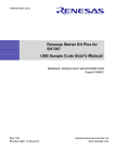
TABLE OF CONTENTS
TABLE OF CONTENTS.........................................................................................................................................i
1. Introduction ................................................................................................................................................... 1-1
1.1
Overview..........................................................................................................................................................1-1
1.2
Usage Precautions ............................................................................................................................................1-1
1.2.1
Symbols Used .........................................................................................................................................1-2
1.3
Installation Procedure ......................................................................................................................................1-3
1.4
Product Behavior .............................................................................................................................................1-3
1.5
What You Need to Get Started (Not included in this product) ........................................................................1-4
1.5.1
Recommended Host Computer Environment..........................................................................................1-4
2. Setting Up the Hardware .............................................................................................................................. 2-1
2.1
SH7269 CPU Board and the E10A-USB Emulator Configuration ..................................................................2-1
2.2
Switch Setting ..................................................................................................................................................2-1
2.2.1
SH7269 CPU Board DIP Switches Setting .............................................................................................2-2
2.2.2
SH7269 CPU Board Jumper Switch Setting ...........................................................................................2-3
2.3
System Connections and Power-On.................................................................................................................2-4
2.3.1
Connecting the SH7269 CPU Board only...............................................................................................2-4
2.3.2
Connecting the SH7269 CPU Board and the SH7269 optional board (M3A-HS64G01 or M3A-HS64G02)
................................................................................................................................................................2-4
2.4
Disconnect the System Power Supply..............................................................................................................2-5
3. Setting Up the Software................................................................................................................................ 3-1
3.1
3.1.1
3.2
About the High-performance Embedded Workshop........................................................................................3-1
High-performance Embedded Workshop Installation.............................................................................3-1
Set Up the E10A-USB Emulator Software ......................................................................................................3-4
3.2.1
E10A-USB Software Installation Procedure...........................................................................................3-4
3.2.2
Set Up the E10A-USB Emulator.............................................................................................................3-8
4. Executing the Software................................................................................................................................. 4-1
4.1
Execute the Sample Software...........................................................................................................................4-1
4.1.1
Prepare to Download the Sample Software.............................................................................................4-1
4.1.2
SH7269 CPU Board and E10A-USB Startup (High-performance Embedded Workshop Startup).........4-1
4.1.3
E10A-USB Emulator Connection Error Dialog......................................................................................4-5
4.1.4
How to Download the Sample Software .................................................................................................4-7
5. Creating and Running a New Project Workspace ........................................................................................ 5-1
5.1
Create a New Project Workspace.....................................................................................................................5-1
5.1.1
Prepare to Create a New Project Workspace...........................................................................................5-1
5.1.2
How to Create a New Project Workspace...............................................................................................5-1
5.2
How To Set Up the Flash Memory Download.................................................................................................5-8
5.2.1
Set Up the Flash Memory Download......................................................................................................5-8
5.2.2
Specify the Command Batch File Before Downloading .........................................................................5-9
5.2.3
Activate the Command Line Window...................................................................................................5-10
5.3
Add/Modify Hardware Setup Files ................................................................................................................5-10
5.3.1
Copy Hardware Setup Files ..................................................................................................................5-10
5.3.2
Remove the Standard Source Files........................................................................................................5-10
5.3.3
Add Hardware Setup Files ....................................................................................................................5-11
5.3.4
Set Compiler Options............................................................................................................................5-13
5.3.5
Set Link/Library....................................................................................................................................5-14
5.3.6
Describe the Main Function (For Operation Check).............................................................................5-22
SH7269 CPU Board R0K572690C000BR
1.
Introduction
1. Introduction
1.1
Overview
This product consists of the SH7269 CPU Board (board part number: R0K572690C000BR) and the sample software.
This installation manual describes mainly how to set up the SH7269 CPU Board hardware and software. Refer to manuals in
CD-ROM attached with this product for the User’s manual, SH7269 hardware and programming manuals.
If any of above items is missing or damaged, please contact Renesas Electronics Corporation, Renesas Solutions Corp. or Renesas
Electronics Sales Co., Ltd. or its distributor.
To Ensure Safe and Correct Use
Safety precaution:
z This manual uses various pictorial indications to ensure the correct use of the product and
thereby prevent inflicting an injury on users or other people or causing damage to property.
• These
pictorial indications are explained in Section 1.2, "Usage Precautions." Be sure to
understand the contents written in that section before you use the product.
1.2
Usage Precautions
The precautions described here must be observed in order to prevent inflicting an injury on users or other people or causing damage
to property, and to ensure that this product is used safely.
To ensure the correct use, be sure to read these precautions and understand the written contents before you use the product. Not all
precautions described in this manual relate to the Renesas product alone, some of them apply to an entire personal computer system
incorporating the Renesas product also.
The following explains the warnings and cautions indicated for the handling of this product.
¾Warning Indication
WARNING
Regarding the handling of this product:
z Do not use this product outdoors. It can only be used indoors.
• Do not let foreign matters such as water, pieces of metal or inflammable material get into the
board or connectors.
Regarding installation:
• Do not install the product in humid or wet places. Should water get into the internal circuit of the
product, an unrecoverable fault may result.
Regarding the working environment:
• The upper-limit ambient temperature at which this product can be used (i.e., rated maximum
temperature) is 50°C. Make sure this rated maximum temperature is not exceeded.
R20UT0160EJ0100 Rev.1.00
Dec. 08, 2011
1-1
SH7269 CPU Board R0K572690C000BR
1.
Introduction
¾Caution Indication
CAUTION
Regarding the reconstruction of this product:
• Do not reconstruct this product. If the product has got out of order for reasons of disassembly or
reconstruction, requests for repair may not be accepted.
Regarding the handling of this product:
z Handle this product with caution, not to let it drop or fall down or apply strong mechanical shock.
z Do not touch the communication interface connector pins or other connector pins directly with
your hand. The internal circuit may be broken by static electricity.
z When moving this product to another place of installation, be careful not to apply strong vibration
or mechanical shock to it.
z After connecting each piece of equipment with cable, check the cables again to see that they are
connected correctly. For details on how to connect, refer to Chapter 2, "
Setting Up the
Hardware".
z Before turning on the power for each connected piece of equipment, make sure you’ve finished
connecting all cables. Do not connect or disconnect any cable when the power is turned ON.
Regarding the operating procedure for this product:
Note
• Exceptional
conditions or precautions are noted in an operation procedure or explanatory
description when it is necessary to call the user’s attention.
1.2.1
Symbols Used
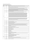
Table 1.2.1 lists the symbols used in this manual.
Table 1.2.1 Symbols
Symbol
[Menu -> Menu Option]
Description
The arrow "->" indicates menu options.
Example: [File] -> [Save As…]
"File name"
" … " is used to indicate file names, directory, or button of dialog box.
"Directory"
Example :"C:\Workspace\Sample_software\sh7269_sample"
"Button"
"OK" button
"resetprg.c"
R20UT0160EJ0100 Rev.1.00
Dec. 08, 2011
1-2
SH7269 CPU Board R0K572690C000BR
1.3
1.
Introduction
Installation Procedure
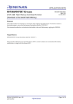
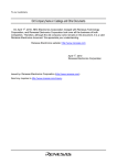
In this manual, follow the procedure indicated in Figure 1.3.1 to install the SH7269 CPU Board.
(1) Prepare development tools (Not included in this product)
Chapter 1
(2) Set up the hardware
Chapter 2
(3) Set up the software
Chapter 3
(4) Execute the sample software
Chapter 4
(5) Create new software
Chapter 5
Figure 1.3.1 SH7269 CPU Board Installation Procedure
1.4
Product Behavior
This product (hardware and software) was developed for only providing users with experience on the specifications and
development environment of the SH7269 MCU, and does not guarantee the results arising from the use of this product.
To use this product, the type of the host computer is specified for its operating environment (IBM PC/AT and its compatible).
However, it only indicates the operating environment assumed by Renesas, and does not guarantee that the SH7269 CPU Board
operates normally in all relevant types of machines or in all relevant environments (e.g., device driver and peripheral devices).
R20UT0160EJ0100 Rev.1.00
Dec. 08, 2011
1-3
SH7269 CPU Board R0K572690C000BR
1.5
1.
Introduction
What You Need to Get Started (Not included in this product)
Following items are not included in this product and should be prepared by user.
¾For the SH7269 CPU Board
Prepare following power supply to supply power to the SH7269 CPU Board.
Table 1.5.1 Power Supply (For the SH7269 CPU Board)
No.
1
Item
Remarks
5 V DC output regulated power supply
1.5 A min.
¾For the Development Environment
This manual describes how to install this product using the Renesas development tools.
To install this product as described in this manual, prepare following Renesas development tools.
Table 1.5.2 Renesas Development Tools
No.
Item
2
E10A-USB Emulator for the SuperH RISC engine
Family
HS0005KCU02H
HS0005KCU01H
3
SuperH RISC engine C/C++ Compiler Package
R0C40700XSW09R
Ver.9.03 release02 or later
4
Integrated development environment tool
-
Ver.4.07.00 or later
Part number
Applicable Version
or
Supports the SH-2A device group
High-performance Embedded Workshop
Notes:
(1) If you already have the E10A-USB emulator and are using any MCUs other than the SH-2A group,
purchase a license tool for device group additions to use additional MCUs (not included in this product).
(2) For details on how to set up a new device group in the E10A-USB emulator, refer to 3.2.2,
"Set Up the E10A-USB Emulator" in this manual.
1.5.1
Recommended Host Computer Environment
Followings are the recommended operation environment to use the above Renesas development tools.
Table 1.5.3 Operating Environment for the Renesas Development Tools
Host Computer Specifications
CPU
IBM PC/AT Series and Compatibles
IBM PC or its compatible machine with Pentium III or later (600 MHz or higher
recommended) and USB 1.1/2.0 port (full-speed)
Memory
128 MB or bigger (at least twice the load module size recommended)
Hard disk
100 MB of available hard-disk space
(To reserve the swap area in the hard disk, at least twice of the memory size must
be available. Four times or bigger recommended.)
OS
Windows 2000, Windows XP, Windows Vista (32-bit edition)
Windows 7 (32-bit edition, 64-bit edition)
R20UT0160EJ0100 Rev.1.00
Dec. 08, 2011
1-4
SH7269 CPU Board R0K572690C000BR
2.
Setting Up the Hardware
2. Setting Up the Hardware
2.1
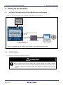
SH7269 CPU Board and the E10A-USB Emulator Configuration
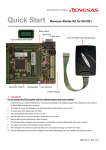
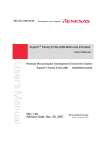
Figure 2.1.1 shows the configuration of the SH7269 CPU Board and the E10A-USB emulator.
5 VDC output
regulated
(1)
power supply
(1.5 A min.)
J4
SH7269 CPU board
R0K572690C000BR
Serial port connector
Debugger
E10A-USB emulator (1)
Host computer (1)
14-pin or 38-pin H-UDI
port connector
Note 1: These items are not included in this product, and must be prepared by user.
Figure 2.1.1 SH7269 CPU Board and the E10A-USB Emulator Configuration
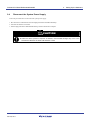
2.2
Switch Setting
Following describes the SH7269 CPU Board switch setting.
CAUTION
• Do not change DIP switches and jumper setting while the SH7269 CPU Board is operating.
Always be sure to turn OFF the power before changing DIP switches or jumper setting. This is
necessary to prevent unrecoverable damage to the SH7269 CPU Board that may otherwise
occur.
R20UT0160EJ0100 Rev.1.00
Dec. 08, 2011
2-1
SH7269 CPU Board R0K572690C000BR
2.2.1
2.
Setting Up the Hardware
SH7269 CPU Board DIP Switches Setting
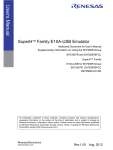
To use the SH7269 CPU Board as described in this manual, be sure to set the DIP switches (SW5 and SW6) to its default setting as
shown in Figure 2.2.1, and listed in Table 2.2.1 and Table 2.2.2.
Board edge
SW5
SW6
ON
ON
Figure 2.2.1 DIP Switches Setting
Table 2.2.1 System Setting DIP Switches Setting (SW5)
Number
Function
Default
Description
SW5-1
Clock operation mode
ON
Clock operation mode 0
SW5-2
Boot mode(MD_BOOT0)
ON
Boots from the memory(with 16 bits bus width)which is connected
SW5-3
Boot mode(MD_BOOT1)
ON
to the CS0 space(boot mode 0)
SW5-4
Boot mode(MD_BOOT2)
OFF
Table 2.2.2 User DIP Switches Setting (SW6)
No.
Function
Default
Description
SW6-1
Connection(EXT#/SDRAM)
OFF
Connected to the SDRAM
SW6-2
Connection(SD#/NAND)
ON
Connected to the SD/MMC card slot
SW6-3
Connect the option
OFF
Connected to the SD card slot
board(VIN#/EXT_SD)
SW6-4
Connect the option board(SSIF#/IEB)
ON
D/A converter
SW6-5
User DIP switch
OFF
–
SW6-6
Input port
OFF
–
R20UT0160EJ0100 Rev.1.00
Dec. 08, 2011
2-2
SH7269 CPU Board R0K572690C000BR
2.2.2
2.
Setting Up the Hardware
SH7269 CPU Board Jumper Switch Setting
To use the SH7269 CPU Board as described in this manual, be sure to set the jumpers to their default setting as shown in Figure
2.2.2 and Table 2.2.3.
1 2 3
Board edge
JP11
3
2
1
JP12
3
2
1
JP13
1
2
Board edge
JP4
3 2 1
JP5
Board edge
Figure 2.2.2 Jumper Setting
Table 2.2.3 SH7269 Group Power Supply Switch Jumper Setting (JP4,JP5,JP11 to JP13)
No.
Default
Description
JP4
Open
Connects PB18 as the A18 (NOR Flash)
JP5
1-2
Connects the PC0/CS0# (NOR Flash)
JP11
1-2
Supplies the power from J4
JP12
1-2
3.3V fixed power supply voltage (supplied from U18)
JP13
1-2
1.25 V fixed power supply voltage (supplied from U16)
R20UT0160EJ0100 Rev.1.00
Dec. 08, 2011
2-3
SH7269 CPU Board R0K572690C000BR
2.3
2.
Setting Up the Hardware
System Connections and Power-On
Be sure to turn OFF the host computer, and not to connect the E10A-USB emulator and the host computer by a USB cable. Then,
follow the procedure below.
2.3.1
Connecting the SH7269 CPU Board only
1. Connect the attached power cable (black: GND, red: +5 V) with the 5 V DV output regulated power supply.
2. Be sure that the SH7269 CPU Board is turned OFF, and connect the other side of the attached power cable (black: GND, red:
+5 V) with the power supply connector (J4).
3. Attach the user interface cable to the connector on the target side of the E10A-USB emulator.
4. Attach a USB cable to the connector on the host side of the E10A-USB emulator.
5. Turn ON the host computer (Start the operating system).
6. Turn ON the SH7269 CPU Board (Turn the power ON).
CAUTION
• Make sure the connector is not reversed before connecting with the cable. Failure to do so will
result in a FIRE HAZARD and will damage the SH7269 CPU Board and the E10A-USB emulator.
2.3.2
Connecting the SH7269 CPU Board and the SH7269 optional board (M3A-HS64G01 or
M3A-HS64G02)
1. Plug the attached AC adapter into the electrical outlet.
2. Be sure that the SH7269 optional board is turned OFF, and connect the attached AC adapter with the AC adapter jack
(M3A-HS64G01: J19, M3A-HS64G02: J18).
3. Connect the user interface cable to the connector on the target side of the E10A-USB emulator cable.
4. Connect a USB cable to the connector on the host side of the E10A-USB emulator.
5. Turn ON the host computer (Start the operating system).
6. Turn ON the SH7269 optional board (Turn the power ON).
CAUTION
• Be sure to use the attached AC adapter. Failure of the connection will result in a FIRE HAZARD
and will damage the SH7269 CPU Board, optional board and the E10A-USB emulator.
R20UT0160EJ0100 Rev.1.00
Dec. 08, 2011
2-4
SH7269 CPU Board R0K572690C000BR
2.4
2.
Setting Up the Hardware
Disconnect the System Power Supply
Follow the procedure below to disconnect the system power supply.
1. Disconnect E10A-USB emulator from the High-performance Embedded Workshop.
2. Turn OFF the SH7269 CPU Board.
3. Exit the High-performance Embedded Workshop, and turn OFF the host computer.
CAUTION
• Unless the above power-on
sequence is followed, unrecoverable damage may occur to the
SH7269 CPU Board or the E10A-USB emulator or both.
R20UT0160EJ0100 Rev.1.00
Dec. 08, 2011
2-5
SH7269 CPU Board R0K572690C000BR
2.
Setting Up the Hardware
This page intentionally left blank.
R20UT0160EJ0100 Rev.1.00
Dec. 08, 2011
2-6
SH7269 CPU Board R0K572690C000BR
3.
Setting Up the Software
3. Setting Up the Software
3.1
About the High-performance Embedded Workshop
The High-performance Embedded Workshop is an integrated development environment with a graphical user interface to simplify
the development and debug of applications written in C/C++ and assembly languages for use in Renesas MCUs. Software
development on the SH7269 CPU Board is carried out by the High-performance Embedded Workshop.
For more information about the High-performance Embedded Workshop, refer to the High-performance Embedded Workshop 4
User’s Manual. Following section describes how to install the High-performance Embedded Workshop.
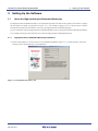
3.1.1
High-performance Embedded Workshop Installation
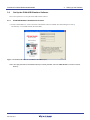
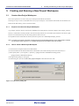
(1) Execute "HewInstMan.exe" stored in the cross tool CD-ROM (SuperH RISC engine C/C++ Compiler Package). The Install
Manager will start up automatically. Click "Installation".
Figure 3.1.1 Installation Procedure (1/4)
R20UT0160EJ0100 Rev.1.00
Dec. 08, 2011
3-1
SH7269 CPU Board R0K572690C000BR
3.
Setting Up the Software
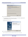
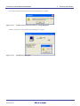
(2) Following dialog box will appear as Figure 3.1.2. Click "Next".
Figure 3.1.2 Installation Procedure (2/4)
Note:If the High-performance Embedded Workshop is already installed, select the "Install a new High-performance
Embedded Workshop" radio button to install it in another directory.
(3) Follow the on-screen instructions to continue.
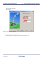
(4) Install the AutoUpdate Utility. Click "Next".
Figure 3.1.3 Installation Procedure (3/4)
Note: If the "AutoUpdate Utility" checkbox is not ticked, above window as Figure 3.1.3 will not appear.
R20UT0160EJ0100 Rev.1.00
Dec. 08, 2011
3-2
SH7269 CPU Board R0K572690C000BR
3.
Setting Up the Software
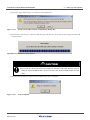
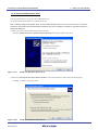
(5) Follow the on-screen instructions to continue installation. When all installation is completed, the following window will appear
as Figure 3.1.4. Click "Exit".
Figure 3.1.4 Installation Procedure (4/4)
R20UT0160EJ0100 Rev.1.00
Dec. 08, 2011
3-3
SH7269 CPU Board R0K572690C000BR
3.2
3.
Setting Up the Software
Set Up the E10A-USB Emulator Software
This section explains how to set up the E10A-USB emulator software.
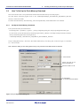
3.2.1
E10A-USB Software Installation Procedure
(1) Execute "HewInstMan.exe" stored in the E10A-USB emulator software CD-ROM. The Install Manager will start up
automatically. Click "Standard Install (Recommended)".
Figure 3.2.1 E10A-USB Software Installation Procedure (1/7)
Note:If the High-performance Embedded Workshop is already installed, select the "Multi Install" to install it in another
directory.
R20UT0160EJ0100 Rev.1.00
Dec. 08, 2011
3-4
SH7269 CPU Board R0K572690C000BR
3.
Setting Up the Software
(2) Following dialog box will appear as Figure 3.2.2. Tick the checkbox of the software to install and click "Install".
Figure 3.2.2 E10A-USB Software Installation Procedure (2/7)
(3) Following dialog box will appear as Figure 3.2.3. Select "SuperH RISC engine Family SH-2A Device Group", a desired device
(e.g. SH72691) and click "Next".
Figure 3.2.3 E10A-USB Software Installation Procedure (3/7)
R20UT0160EJ0100 Rev.1.00
Dec. 08, 2011
3-5
SH7269 CPU Board R0K572690C000BR
3.
Setting Up the Software
(4) Installation will start. Click "Next". Follow the on-screen instructions to continue installation.
Figure 3.2.4 E10A-USB Software Installation Procedure (4/7)
(5) Click "Next" to install the AutoUpdate Utility.
Figure 3.2.5 E10A-USB Software Installation Procedure (5/7)
Note: If the "AutoUpdate Utility" checkbox is not ticked, above dialog box will not appear.
R20UT0160EJ0100 Rev.1.00
Dec. 08, 2011
3-6
SH7269 CPU Board R0K572690C000BR
3.
Setting Up the Software
(6) Following window as Figure 3.2.6 will appear after the installation is completed. Click "Finish".
Figure 3.2.6 E10A-USB Software Installation Procedure (6/7)
(7) Following window will appear when all installation is completed. Click "Exit".
Figure 3.2.7 E10A-USB Software Installation Procedure (7/7)
R20UT0160EJ0100 Rev.1.00
Dec. 08, 2011
3-7
SH7269 CPU Board R0K572690C000BR
3.2.2
3.
Setting Up the Software
Set Up the E10A-USB Emulator
(i) Set Up New Firmware
This section explains how to set up the E10A-USB emulator for the first time.
When the installed E10A-USB emulator firmware supports the SH-2A device group, skip this step and go to paragraph (ii) “Setup
the E10A-USB Emulator Driver”.
To setup the firmware, follow the on-screen instructions to change the DIP switches on the E10A-USB emulator. Figure 3.2.8
shows the DIP switches on the E10A-USB emulator.
Figure 3.2.8 DIP Switches
R20UT0160EJ0100 Rev.1.00
Dec. 08, 2011
3-8
SH7269 CPU Board R0K572690C000BR
3.
Setting Up the Software
(1) Open the sliding switch cover of the E10A-USB emulator and check that the switch (SW1) for setting the emulator is turned
to 1.
(2) Select [All Programs] -> [Start] -> [Renesas High-performance Embedded Workshop] -> [Tools] ->
[Setup Tool for E10A-USB Emulator] -> [SH-2A Device Group]. A setup tool for the E10A-USB emulator will start up.
Figure 3.2.9 E10A-USB Emulator Setup Tool
(a) Device group of the emulator firmware: Shows the name of the device group currently set
(b) Version number of the emulator firmware: Shows the version number of the software for controlling the SH-2A device group in
the E10A-USB emulator
(c) Version number of the setup program: Shows the version number of the setup program
Note: The version numbers shown in the dialog box depend on the version that the E10A-USB emulator supports.
R20UT0160EJ0100 Rev.1.00
Dec. 08, 2011
3-9
SH7269 CPU Board R0K572690C000BR
3.
Setting Up the Software
Notes:
(1) If the version numbers shown in (b) and (c) are the same, the emulator setup is not required. Set up the emulator
only when "-.-.--.---" is shown in (b) or the version number shown in (b) is older than that of (c).
(2) If the connected emulator does not support the SH7269 MCU, following error message will appear to terminate the
setup tool. Purchase a license tool for device group additions for the SH7269 MCU to set up the firmware.
Figure 3.2.10
Error Message
• If the following error message appears, the host computer is not connected to the E10A-USB emulator or the setup
switch (SW1) is turned to 0. If the setup switch (SW1) is 0, set it to 1 and connect the USB cable again. If the [Add New
Hardware Wizard] appears, refer to (ii) "Set up the E10A-USB emulator driver".
Figure 3.2.11
Error Message
R20UT0160EJ0100 Rev.1.00
Dec. 08, 2011
3-10
SH7269 CPU Board R0K572690C000BR
3.
Setting Up the Software
(3) Clicking the "Setup" button (Figure 3.2.9) shows the following dialog box.
Figure 3.2.12
[Setup Tool for SHxxxx E10A-USB Emulator] Dialog Box
(4) Turn the setup switch (SW1) to 0, connect the USB cable again, and click "OK". The system will start setting up the E10A-USB
emulator firmware.
Figur0065 3.2.13Firmware Set Up Started
CAUTION
• Do not turn OFF the power for the host computer or remove the USB cable while the system is
setting up the E10A-USB emulator. Such an act may cause the E10A-USB emulator to break
down.
(5) When the following dialog box appears, the E10A-USB emulator setup is completed.
Figure 3.2.14
Setup Completed
R20UT0160EJ0100 Rev.1.00
Dec. 08, 2011
3-11
SH7269 CPU Board R0K572690C000BR
3.
Setting Up the Software
(6) When the E10A-USB emulator setup has been completed, the following message will appear.
Turn the setup switch (SW1) to 1, connect the USB cable again, and click "OK".
Figure 3.2.15
[Setup Tool for SH-2A E10A-USB Emulator] Dialog Box
Note: Be sure to turn the SW1 to 1 except when using the setup tool.
(7) The following dialog box will appear again. Check if it is the latest version of the firmware, and click "Exit". The new firmware
setup is now completed.
Version numbers
Figure 3.2.16
E10A-USB Emulator Setup Tool (Completed)
Note: The version numbers shown in the dialog box depend on the version that the E10A-USB emulator supports.
R20UT0160EJ0100 Rev.1.00
Dec. 08, 2011
3-12
SH7269 CPU Board R0K572690C000BR
3.
Setting Up the Software
(ii) Set Up the E10A-USB Emulator Driver
Following describes how to set up the E10A-USB emulator driver.
The setup procedure described below is for the Windows XP.
Note: Following dialog boxes appear when the E10A-USB emulator driver is set up for the first time or when the
emulator is connected for the first time after the USB port on the host computer is changed. It may take some time to
appear the dialog box.
(1) [Welcome to the Found New Hardware Wizard] is activated.
Select the "Install from the list or specific location [Advanced]" radio button, and then click "Next".
Figure 3.2.17
Found New Hardware Wizard (1/4)
(2) Select the "Search for the best driver in these locations" radio button and tick the "Search removable media (floppy,
CD-ROM...)" checkbox. Then click "Next".
Figure 3.2.18
Found New Hardware Wizard (2/4)
R20UT0160EJ0100 Rev.1.00
Dec. 08, 2011
3-13
SH7269 CPU Board R0K572690C000BR
3.
Setting Up the Software
(3) Search for the driver in the CD-ROM, select "<drive>:¥drivers¥usb¥xp¥e1usb_cdr.inf", and then click "Next". The underlined
'xp' indicates the version of the operating system (This example is for Windows XP).
Figure 3.2.19
Found New Hardware Wizard (3/4)
Note: When an error message saying the software you are installing has not passed Windows Logo testing.. appears,
just click "Continue Anyway". The version numbers shown in the dialog box depend on the version that the
E10A-USB emulator supports.
(4) [Completing the Found New Hardware Wizard] dialog box will appear. Click "Finish". The E10A-USB emulator driver setup is
now completed.
Figure 3.2.20
Found New Hardware Wizard (4/4)
R20UT0160EJ0100 Rev.1.00
Dec. 08, 2011
3-14
SH7269 CPU Board R0K572690C000BR
3.
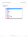
Setting Up the Software
(5) Activate the Device Manager to confirm whether the USB controller driver has been installed.
¾Activating Device Manager
[Start] -> [Control Panel] and double-click [System] icon. In [Properties] dialog box, click the [Hardware] tab, and then click
[Device Manager].
Figure 3.2.21
Confirming the USB Controller Driver is Installed (Device Manager)
R20UT0160EJ0100 Rev.1.00
Dec. 08, 2011
3-15
SH7269 CPU Board R0K572690C000BR
3.
Setting Up the Software
This page intentionally left blank.
R20UT0160EJ0100 Rev.1.00
Dec. 08, 2011
3-16
SH7269 CPU Board R0K572690C000BR
4.
Executing the Software
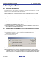
4. Executing the Software
4.1
Execute the Sample Software
This product comes with the sample software for checking the hardware operation and referring for the software development.
Following describes how to download the load module of the sample software.
Note: Set DIP switches (SW5, and SW6) on the SH7269 CPU Board as the default setting to execute the sample
software.
4.1.1
Prepare to Download the Sample Software
Copy "Sample_software" directory stored in the CD-ROM into the working directory of the host computer. When the
"Sample_software" directory is created with a read-only attribute, cancel the read-only attribute. Do not use double-byte characters
in the directory path. Presence of such characters may cause the wrong operation of the cross tools.
The explanation below assumes that this directory has been copied to the "C:¥WorkSpace directory".
Notes:
(1) The High-performance Embedded Workshop and the E10A-USB emulator software must be installed to download
the load module of the sample software. (Refer to Chapter 0)
(2) The SuperH RISC engine C/C++ Compiler Package must be installed to modify the sample software. Refer to 1.5
What You Need to Get Started (Not included in this product).
4.1.2
SH7269 CPU Board and E10A-USB Startup (High-performance Embedded Workshop Startup)
(1) Connect the host computer and the E10A-USB emulator.
(2) Connect the SH7269 CPU Board and the E10A-USB emulator. (Do not turn ON the power for the CPU board yet.)
(3) Select [Start] menu -> [All Programs] -> [Renesas] -> [High-performance Embedded Workshop] (folder)
-> [High-performance Embedded Workshop].
(4) The [Welcome!] dialog box will appear.
Select the "Browse to another project workspace" radio button and click "OK".
Figure 4.1.1 [Welcome!] Dialog Box
Note: A project workspace is a work area for user to store projects and their configurations. A project consists of a
configuration necessary to create programs or final binary files and a set of files. For more information about the
project workspace, refer to the SuperH RISC engine High-performance Embedded Workshop 4 User’s Manual.
R20UT0160EJ0100 Rev.1.00
Dec. 08, 2011
4-1
SH7269 CPU Board R0K572690C000BR
4.
Executing the Software
(5) The [Open Workspace] dialog box will appear, specify the following directory.
Directory to store the sample software:
"C:¥WorkSpace¥Sample_software¥sh7269_sample"
(6) After specifying the directory, select the following file and click "Select" to open.
Figure 4.1.2 [Open Workspace] Dialog Box
Note: The dialog box that indicates the directory in the workspace has been moved may appear at the first time. Click
"Yes" to continue.
(7) The [Select Emulator mode] dialog box will appear.
Select "SH72691" as the device, and "E10A-USB Emulator" as the emulator mode. Then, click "OK".
Figure 4.1.3 [Select Emulator mode] Dialog Box
R20UT0160EJ0100 Rev.1.00
Dec. 08, 2011
4-2
SH7269 CPU Board R0K572690C000BR
4.
Executing the Software
Note: A message "Please choose driver" will appear at the first time. Click "OK" to show the following window to select
the driver. Select "Renesas E-Series USB Driver".
Figure 4.1.4 [Driver Details] Dialog Box
(8) Following dialog box will appear and start to connect the emulator.
Figure 4.1.5 [Connecting] Dialog Box
(9) The following dialog box will appear.
Figure 4.1.6 Dialog Box to request the Reset signal input
R20UT0160EJ0100 Rev.1.00
Dec. 08, 2011
4-3
SH7269 CPU Board R0K572690C000BR
4.
Executing the Software
(10) Turn ON the power for the SH7269 CPU Board.
(11) Press the reset button (SW2) on the SH7269 CPU Board and click "OK" on the dialog box.
(12) If the reset signal cannot be detected, the following dialog box will appear. Click "Ignore" to issue an internal reset to the CPU
and to start up the system.
Figure 4.1.7 [Cannot find /RESET Signal] Dialog Box
(13) When the message "Connected" appears in [Output] window of the High-performance Embedded Workshop, the E10A-USB
emulator startup is now completed.
Figure 4.1.8 [Output] Window
R20UT0160EJ0100 Rev.1.00
Dec. 08, 2011
4-4
SH7269 CPU Board R0K572690C000BR
4.1.3
4.
Executing the Software
E10A-USB Emulator Connection Error Dialog
When the E10A-USB emulator does not start up, the following dialog box will appear.
(a) When the following dialog box appears and the emulator cannot be activated as (11) on the top of page 4-5, the SH7269 CPU
Board system power may not be supplied. Check the power supply of the SH7269 CPU Board.
Figure 4.1.9 [Can not find /RESET signal] Dialog Box
(b) When the following dialog box appears, the H-UDI pins and the H-UDI port connector may not be connected correctly.
Check the connection between the H-UDI pins and the H-UDI port connector.
Figure 4.1.10
[Check the Connection] Dialog Box
(c) When the following dialog box appears, the E10A-USB emulator firmware may not be set up correctly. Use the setup tool or the
license tool for device group addition to set up the firmware for the device group to use.
Figure 4.1.11
[The Product Currently Connected] Dialog Box
(d) When the following dialog box appears, the version of the firmware set up in the E10A-USB emulator may be old. Use the setup
tool to set up the appropriate version of the firmware.
Figure 4.1.12
[The Version of the Emulator Firmware is incorrect] Dialog Box
R20UT0160EJ0100 Rev.1.00
Dec. 08, 2011
4-5
SH7269 CPU Board R0K572690C000BR
4.
Executing the Software
(e) If the driver has not been set up correctly, the following dialog box will appear.
Figure 4.1.13
[Unable to restore the previous driver setting] Dialog Box
(f) When a wrong device is selected, the following dialog box will appear.
Figure 4.1.14
[Invalid CPU] Dialog Box
R20UT0160EJ0100 Rev.1.00
Dec. 08, 2011
4-6
SH7269 CPU Board R0K572690C000BR
4.1.4
4.
Executing the Software
How to Download the Sample Software
This section describes how to download the load module of the sample software.
Download the load module in the SH7269 CPU Board external flash memory.
For details about flash memory download setting, refer to the SuperH Family E10A-USB Emulator User’s Manual.
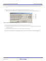
(1) Set up the flash memory download function
From [Setup] menu -> [Emulator] -> [System…], open [Configuration] dialog box and then [Loading flash memory] tab.
For "File Name", specify the flash memory download program "fmtool_r0k57269.mot". The sample workspace shall have the
flash memory download program in the following directory.
"C:¥WorkSpace¥Sample_software¥sh7269_sample¥fmtool_r0k57269"
As shown in Figure 4.1.15, select "Enable" for Loading Flash Memory. Check "File name", "Bus width of flash memory" and
"Entry point" are set as shown below, and click "OK".
Notes:
(1) Check the configuration on the "Loading flash memory" tab every time the E10A-USB emulator is attached.
(2) The writing module erases the sector in the flash memory in the "fmtool_r0k57269.mot". Select "Disable" radio
button for "Erasing flash memory".
Figure 4.1.15
[Configuration] Dialog Box
R20UT0160EJ0100 Rev.1.00
Dec. 08, 2011
4-7
SH7269 CPU Board R0K572690C000BR
4.
Executing the Software
(2) Specify the command batch file before downloading
Execute the script file "fmtool_r0k57269.hdc", consisting of the access timing and the bus control signal setting for the SH7269
CPU Board flash memory before downloading the sample software.
The following script file is assumed to be stored in the sample workspace.
"C:¥WorkSpace¥Sample_software¥sh7269_sample¥fmtool_r0k57269"
Open [Debug] menu -> [Debug Settings], and select [Options] tab. Check that the items on this tab are set as shown below.
Command batch file load timing (B): Before download of modules
Command line batch processing (L): "$(WORKSPDIR)¥ fmtool_r0k57269¥fmtool_r0k57269.hdc"
Figure 4.1.16
[Debug Settings] Dialog Box
(3) Activate the command line window
When downloading the load module of the sample software, activate the [Command Line] window to check whether the script
file is running.
Select [View] menu -> [Command Line] to check whether [Command Line] window is opened.
Note: If the script file is not executed, downloading the load module into the flash memory cannot be completed.
R20UT0160EJ0100 Rev.1.00
Dec. 08, 2011
4-8
SH7269 CPU Board R0K572690C000BR
4.
Executing the Software
(4) Download the sample load module
Select [Debug] menu -> [Download modules] to select the sample load module. Figure 4.1.17 shows the download operation
window.
Immediately after the sample load module is selected, the script file is automatically executed. Then, the system starts
downloading the sample load module.
Figure 4.1.17
[Download Operation] Window
R20UT0160EJ0100 Rev.1.00
Dec. 08, 2011
4-9
SH7269 CPU Board R0K572690C000BR
4.
Executing the Software
(5) Download completed
When the downloading of the sample load module is completed, the program counter will appear in "resetprg.c".
(See Figure 4.1.18)
Figure 4.1.18
Download Completed
R20UT0160EJ0100 Rev.1.00
Dec. 08, 2011
4-10
SH7269 CPU Board R0K572690C000BR
4.
Executing the Software
(6) Execute the program
Select "Go" from the [Debug] menu to execute the software (See Figure 4.1.19).
If the sample software is downloaded correctly, LED2 on the SH7269 CPU Board is on or off in half-second intervals.
Figure 4.1.19
Executing the Program
Note: The contents of "resetprg.c" may depend on the version of the sample software. If an error occurs or the sample
software does not operate correctly, the hardware or the software may not have been setup correctly. Check the
setup procedures in Chapter 2 and Chapter 0.
R20UT0160EJ0100 Rev.1.00
Dec. 08, 2011
4-11
SH7269 CPU Board R0K572690C000BR
4.
Executing the Software
This page intentionally left blank.
R20UT0160EJ0100 Rev.1.00
Dec. 08, 2011
4-12
SH7269 CPU Board R0K572690C000BR
5.
Creating and Running a New Project Workspace
5. Creating and Running a New Project Workspace
5.1
Create a New Project Workspace
This section explains how to create a new project workspace in the SH7269 CPU Board.
Following are steps to create a load module from a new project workspace, to download the load module into the SH7269 CPU
Board external flash memory, and to execute the module.
5.1.1
Prepare to Create a New Project Workspace
Copy "Sample_software" directory stored in the CD-ROM to the working directory of the host computer. If the "Sample_software"
directory is created with a read-only attribute, cancel the read-only attribute. Do not use double-byte characters in the directory path.
Presence of such characters may cause the wrong operation of the cross tools.
The explanation below assumes that this directory has been copied to the "C:¥WorkSpace¥sample_software"
Note: To create a new project workspace, the High-performance Embedded Workshop, E10A-USB emulator software,
and the SuperH RISC engine C/C++ Compiler Package must be installed in the host computer.
5.1.2
How to Create a New Project Workspace
(1) Connect the host computer and the E10A-USB emulator.
(2) Connect the SH7269 CPU Board and the E10A-USB emulator. (Do not turn ON the power for the CPU board yet.)
(3) Select [Start] menu -> [All Programs] -> [Renesas] -> [High-performance Embedded Workshop] (folder)
-> [High-performance Embedded Workshop].
(4) The [Welcome!] dialog box will appear.
(5) In this dialog box, select the "Create a new project workspace" radio button and click "OK".
Figure 5.1.1 [Welcome!] Dialog Box
R20UT0160EJ0100 Rev.1.00
Dec. 08, 2011
5-1
SH7269 CPU Board R0K572690C000BR
5.
Creating and Running a New Project Workspace
(6) Project Generator will start.
This manual uses "test" for the workspace name. Check that the Directory, CPU family and Tool chain are set as follows, then
click "OK".
Figure 5.1.2 [New Project Workspace] Dialog Box
(7) In the [New Project-1/9-Select Target CPU] dialog box, select "SH-2A FPU" for the CPU Series, and "Other" for the CPU Type
from the drop-down list.
Figure 5.1.3 [New Project-1/9] Dialog Box
R20UT0160EJ0100 Rev.1.00
Dec. 08, 2011
5-2
SH7269 CPU Board R0K572690C000BR
5.
Creating and Running a New Project Workspace
(8) Specify the global options from [New Project-2/9] dialog box.
FPU: Single
Round to: Zero
Figure 5.1.4 [New Project-2/9] Dialog Box
(9) Follow the on-screen instructions of the [New Project-3/9] and [New Project-4/9] dialog boxes. Leave the default setting in this
installation step (Select the checkbox as appropriate). Click "Next".
R20UT0160EJ0100 Rev.1.00
Dec. 08, 2011
5-3
SH7269 CPU Board R0K572690C000BR
5.
Creating and Running a New Project Workspace
(10) In the [New Project-5/9] dialog box, set up the stacks as follows and click "Next". Change the stack size as appropriate.
Stack Pointer Address: H'FFF90000
Stack Size: H'400
Figure 5.1.5 [New Project-5/9] Dialog Box
(11) In the [New Project-6/9] dialog box, set up a vector.
Leave default setting (the "Vector Definition Files" checkbox is selected) and click "Next".
R20UT0160EJ0100 Rev.1.00
Dec. 08, 2011
5-4
SH7269 CPU Board R0K572690C000BR
5.
Creating and Running a New Project Workspace
Figure 5.1.6 [New Project-6/9] Dialog Box
R20UT0160EJ0100 Rev.1.00
Dec. 08, 2011
5-5
SH7269 CPU Board R0K572690C000BR
5.
Creating and Running a New Project Workspace
(12) In the [New Project-7/9] dialog box, set up the Target as below. Select the "Target type" and then select "Targets".
Target type: SH2A-FPU
Targets: SH7266 E10A-USB SYSTEM (SH2A-FPU)
Figure 5.1.7 [New Project-7/9] Dialog Box
(13) Confirm setting in [New Project-8/9] and [New Project-9/9] dialog boxes and click "Finish".
Follow the on-screen instructions to finish the Project Generator.
The High-performance Embedded Workshop is activated and automatically generates the standard source files for the SH-2A
device group.
(14) After the High-performance Embedded Workshop is activated, connect the E10A-USB emulator.
The E10A-USB emulator can be connected by switching session for the E10A-USB emulator as shown in Figure 5.1.8
Note: A dialog box to notify that the default session has been modified will appear. Click “Yes”.
Select the session
Figure 5.1.8 [E10A-USB Emulator Connection Setup] Window
R20UT0160EJ0100 Rev.1.00
Dec. 08, 2011
5-6
SH7269 CPU Board R0K572690C000BR
5.
Creating and Running a New Project Workspace
(15) [Select Emulator mode] dialog box will appear.
For details to connect the E10A-USB emulator, refer to 4.1.2 SH7269 CPU Board and E10A-USB Startup (High-performance
Embedded Workshop Startup) step 7 and later.
Figure 5.1.9 [Select Emulator mode] Dialog Box
(16) Execute build processing.
Select [Build] menu -> [Build] to execute the build processing.
After the E10A-USB emulator has been connected, execute build processing once without modifying the standard source file.
If a build error occurs here, the SuperH RISC engine C/C++ Compiler Package may not have been installed correctly.
R20UT0160EJ0100 Rev.1.00
Dec. 08, 2011
5-7
SH7269 CPU Board R0K572690C000BR
5.2
5.
Creating and Running a New Project Workspace
How To Set Up the Flash Memory Download
This section describes how to set up the SH7269 CPU Board external flash memory down load program.
The flash memory download program stored in the "C:¥WorkSpace¥Sample_software¥sh7269_sample¥fmtool_r0k57269"
directory is used in this manual.
For details about flash memory download setting, refer to the SuperH Family E10A-USB Emulator User’s Manual.
5.2.1
Set Up the Flash Memory Download
• Set up the flash memory download function
From [Setup] menu -> [Emulator] -> [System…], select [Configuration] dialog box, and open [Loading flash memory] tab.
For "File Name", specify the flash memory download program "fmtool_r0k57269". The sample workspace shall have the flash
memory download program in the following directory.
"C:¥WorkSpace¥Sample_software¥sh7269_sample¥fmtool_r0k57269¥fmtool_r0k57269"
Set up "Loading flash memory", "File name", "Bus width of flash memory" and "Entry point" as shown in Figure 5.2.1 and Table
5.2.1. Then click "OK".
Note: Check the setting of the Loading flash memory every time the E10A-USB emulator is attached.
Select “Enable”
Specify the path as the
"fmtool_r0k57269.mot"
Set the bus width to 16-bit
Set H'FFF80000
for the Writing module address.
Figure 5.2.1 [Configuration] Dialog Box
R20UT0160EJ0100 Rev.1.00
Dec. 08, 2011
5-8
SH7269 CPU Board R0K572690C000BR
5.
Creating and Running a New Project Workspace
Table 5.2.1 Flash Memory Setting
Loading flash memory
Enable
Erasing flash memory
Disable
File name
C:\WorkSpace\Sample_software\ sh7269_sample\fmtool_r0k57269\
fmtool_r0k57269.mot
Bus width of flash memory
16-bit
Flash memory erasing time
-
All erasing module address
-
Writing module address
H'FFF80000
Access size
1
5.2.2
Specify the Command Batch File Before Downloading
Execute the script file "fmtool_r0k57269.hdc", consisting of the access timing and bus control signal setting for theSH7269 CPU
Board flash memory before downloading the flash memory download program.
Open [Debug] menu -> [Debug Settings] dialog box, and select [Options] tab.
Set up the items on this tab as shown below.
• Command batch file load timing (B): Before download of modules
• Command line batch processing (L):
"C:¥WorkSpace¥Sample_software¥sh7269_sample¥fmtool_r0k57269¥fmtool_r0k57269.hdc"
Figure 5.2.2 [Debug Settings] Dialog Box
Note: The “Download modules after build” checkbox is selected as default. However, clear this checkbox, and select
“Reset CPU after download module”, as shown above.
R20UT0160EJ0100 Rev.1.00
Dec. 08, 2011
5-9
SH7269 CPU Board R0K572690C000BR
5.2.3
5.
Creating and Running a New Project Workspace
Activate the Command Line Window
Select [View] menu -> [Command Line] to open the [Command Line] window.
When downloading the load modules, activate the [Command Line] window to check whether the script file is executed.
Note: If the script file is not executed, downloading the load modules into the flash memory cannot be completed.
5.3
Add/Modify Hardware Setup Files
To operate the software on the SH7269 CPU Board, the hardware-dependent part of the SH7269 CPU Board must be set up.
Add or modify the SH7269 CPU Board hardware setting of the standard source files, which are automatically generated when you
created a new project. How to add or modify the hardware setup files is described below.
The hardware-dependent setting means the access timing to the external memory (flash memory, and SDRAM), the operating clock
setting, and the cache memory setting.
5.3.1
Copy Hardware Setup Files
Copy the "HardwareSetup" directory stored in the CD-ROM into the new project workspace directory "C:¥WorkSpace¥test",
created in 0.
The explanation given below assumes that the hardware setup files are stored in "C:¥WorkSpace¥test¥HardwareSetup" directory.
5.3.2
Remove the Standard Source Files
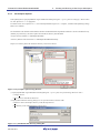
(1) Select [Project] -> [Remove Files...].
Figure 5.3.1 Remove Files (1/2)
R20UT0160EJ0100 Rev.1.00
Dec. 08, 2011
5-10
SH7269 CPU Board R0K572690C000BR
5.
Creating and Running a New Project Workspace
(2) Select the files "dbsct.c", "intprg.c", "resetprg.c", "sbrk.c", and "vecttbl.c" from the [Remove Project Files] dialog box, and click
"Remove".
Figure 5.3.2 Remove Files (2/2)
5.3.3
Add Hardware Setup Files
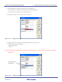
(1) Select [Project] -> [Add Files...].
Figure 5.3.3 Add Files (1/3)
R20UT0160EJ0100 Rev.1.00
Dec. 08, 2011
5-11
SH7269 CPU Board R0K572690C000BR
5.
Creating and Running a New Project Workspace
(2) From the copied hardware setup files "C:¥WorkSpace¥test¥HardwareSetup" directory, add the files listed below.
"bsc_cs0c.c", "bscsdram.c", "cache.c", "cpg.c", "dbsct.c", "hwsetup.c", "intprg.c", "lowsrc.c",
"resetprg.c", "sbrk.c", "siochar.c", "siorw.c", "vecttbl.c"
(Select the "Relative Path" checkbox)
Select the “Relative Path”
checkbox
Figure 5.3.4 Add Files (2/3)
(3) Confirm that the files have been added as shown below.
Figure 5.3.5 Add Files (3/3)
R20UT0160EJ0100 Rev.1.00
Dec. 08, 2011
5-12
SH7269 CPU Board R0K572690C000BR
5.3.4
5.
Creating and Running a New Project Workspace
Set Compiler Options
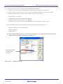
Select [Build] menu, open [SuperH RISC engine Standard Toolchain] dialog box -> [C/C++] tab. Set "Category", "Show entries
for" and "Options C/C++" as appropriate.
For details on how to set "Options C/C++", refer to the SuperH RISC engine C/C++ Compiler, Assembler and Optimizing Linkage
Editor User’s Manual.
The installation in this manual assumes that the SH7269 CPU Board hardware-dependent include file is stored in another directory
(default: project directory), the relative path to the include file directory must be added.
• Project directory (default): "C:¥WorkSpace¥test¥test"
• Directory that stores the include files: "C:¥WorkSpace¥test¥HardwareSetup"
Steps to set a relative path to the include file directory are shown as follows.
Figure 5.3.6 [Compiler Option Setup] Window
(1) Open [SuperH RISC engine Standard Toolchain] dialog box -> [C/C++] tab, set up as following, then click "Add...".
• Category: Source
• Show entries for: Include file directories
(2) Open [Add include file directory] dialog box, set up as shown below, and click "OK".
• Relative to: Select "Workspace directory" from the drop-down list.
• Sub-directory: Enter "HardwareSetup" in the text box.
Figure 5.3.7 [Add include file directory] Dialog Box
R20UT0160EJ0100 Rev.1.00
Dec. 08, 2011
5-13
SH7269 CPU Board R0K572690C000BR
5.3.5
5.
Creating and Running a New Project Workspace
Set Link/Library
Select [Build] menu, open the [SuperH RISC engine Standard Toolchain] dialog box, and select [Link/Library] tab. Set "Category",
"Show entries for", and "Option Link/Library" as appropriate.
For details on how to set optimization linker options, refer to the SuperH RISC engine C/C++ Compiler, Assembler and Optimizing
Linkage Editor User’s Manual.
This section describes how to change section setting.
Figure 5.3.8 [Link/Library Setup] Window
R20UT0160EJ0100 Rev.1.00
Dec. 08, 2011
5-14
SH7269 CPU Board R0K572690C000BR
5.
Creating and Running a New Project Workspace
(a) Set Section to use the SH7269 CPU board
(1)To use the SH7269 CPU board ,the section must be allocated as follows.
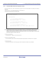
Select [Build] menu -> open the [SuperH RISC engine Standard Toolchain] dialog box, and select [Link/Library] tab. Set
following items as below, and click “Modify”.
・ Category: Section
・ Show entries for: Section
Figure 5.3.9 Section Setting (1/2)
(2) Enter "0x00001100" in the [Address] as shown in Figure 5.3.10, and click "OK".
Figure 5.3.10
Section Setting (2/2)
R20UT0160EJ0100 Rev.1.00
Dec. 08, 2011
5-15
SH7269 CPU Board R0K572690C000BR
5.
Creating and Running a New Project Workspace
(b) Section modification example (using the cache memory setting function)
To use "io_init_cache function (cache memory setting)", the section must be allocated to the CS0 cache-disabled space. The
following describes steps to allocate the section to the CS0 cache-disabled space.
For the details on the cache memory, refer to Chapter 8 Cache and Chapter 9 BSC in the SH7268 Group, SH7269 Group
Hardware Manual.
(1) Select [Build] menu -> open the [SuperH RISC engine Standard Toolchain] dialog box, and select [Link/Library] tab. Set
following items as below, and click “Edit”.
• Category: Section
• Show entries for: Section
Figure 5.3.11
Section Setting (1/6)
(2) The [Section] dialog box will appear. Click "Add…".
Figure 5.3.12
Section Setting (2/6)
R20UT0160EJ0100 Rev.1.00
Dec. 08, 2011
5-16
SH7269 CPU Board R0K572690C000BR
5.
Creating and Running a New Project Workspace
(3) The [Section address] dialog box will open. Enter "0x203FF000" in the [Address] as shown in Figure 5.3.13, and click "OK".
Figure 5.3.13
Section Setting (3/6)
(4) The Section address is added and the display returns to [Section] dialog box. Select the blank space of Section as shown in
Figure 5.3.14, and click "Add…".
Figure 5.3.14
Section Setting (4/6)
R20UT0160EJ0100 Rev.1.00
Dec. 08, 2011
5-17
SH7269 CPU Board R0K572690C000BR
5.
Creating and Running a New Project Workspace
(5) The [Add section] dialog box will open. Enter "PCACHE" in the [Section name] as shown in Figure 5.3.15, and click "OK".
The [CACHE] section is defined in the "cache.c" source file. The first character "P" stands for section P.
Figure 5.3.15
Section Setting (5/6)
(6) The section name is added, and the display returns to the [Section] dialog box. Confirm if the section has been set as shown in
Figure 5.3.16, and click "OK".
The display returns to the [SuperH RISC engine Standard Toolchain] dialog box, and click "OK" to complete the setting.
Allocate to the
CS0 cache-disabled space
Figure 5.3.16
Section Setting (6/6)
R20UT0160EJ0100 Rev.1.00
Dec. 08, 2011
5-18
SH7269 CPU Board R0K572690C000BR
5.
Creating and Running a New Project Workspace
(c) Section modification example (Change Section B to the SDRAM area)
The following shows an example for reallocating section B to the SDRAM area.
For details on the section setting, refer to paragraph (a) above.
(1) In [Section] dialog box, select section B, and click "Remove".
Figure 5.3.17
Change Section (1/2)
(2) In [Section] dialog box, add section B to the SDRAM area as shown in Figure 5.3.18.
Example: Adds a section to the SDRAM
• Address: 0x0C000000
• Section: B
Note: For details on the SDRAM area on the SH7269 CPU Board, refer to “1.17 Memory Maps” in the SH7269 CPU Board
User’s Manual.
Add section B to the
SDRAM area
Figure 5.3.18
Change Section (2/2)
R20UT0160EJ0100 Rev.1.00
Dec. 08, 2011
5-19
SH7269 CPU Board R0K572690C000BR
5.
Creating and Running a New Project Workspace
(c) Setting example (Transfers the vector table section DINTTBL to the internal RAM)
Transfer the vector table to the internal RAM and use the register bank to accelerate the interrupt response.
To transfer the vector table, set the Section of the vector table on the ROM as "DINTTBL", the Section on the transfer
destination RAM as "RINTTBL" in the file "dbsct.c" added in section 5.3.3 in this manual.
Section definition for vector table:
• Section name for the vector table (ROM section): DINTTBL
• Transfer destination section name (RAM section): RINTTBL
Following are steps to move the DINTTBL section from ROM to the internal RAM in the sample program.
(1) Set the RINTTBL section to the internal RAM area in [Section] dialog box as shown in Figure 5.3.19.
¾Example for adding section to internal RAM area
• Address: 0xFFF80000
• Section: RINTTBL
Note: When setting the address as above, set the CPU vector base register. This sample software sets the vector base
register in the reset exception handling in the “resetprg.c” file.
ROM area
Reallocate the RINTTBL,
B, and R sections to
0xFFF80000
Figure 5.3.19
Change Section (1/3)
R20UT0160EJ0100 Rev.1.00
Dec. 08, 2011
RAM area
5-20
SH7269 CPU Board R0K572690C000BR
5.
Creating and Running a New Project Workspace
(2) Open [Link/Library] tab and set the items below, and click "Add…".
• Category: Output
• Show entries for: ROM to RAM mapped sections
Figure 5.3.20
Change Section (2/3)
Note: This sample software sets the section initialization table in "dbsct.c" file.
(3) Set the items as below in the [Add Rom to Ram] dialog box, and click "OK".
Return to [SuperH RISC engine Standard Toolchain] dialog box, and click "OK" to complete the setting.
• ROM section: DINTTBL
• RAM section: RINTTBL
Figure 5.3.21
Change Section (3/3)
R20UT0160EJ0100 Rev.1.00
Dec. 08, 2011
5-21
SH7269 CPU Board R0K572690C000BR
5.3.6
5.
Creating and Running a New Project Workspace
Describe the Main Function (For Operation Check)
In the main function (test.c source file), describe the program to turn ON the LED (LED2 on the SH7269 CPU Board is
illuminated).
• Open the source file "C:¥WorkSpace¥test¥test¥test.c" with an editor, etc.
• Describe the following program to turn ON the LED.
Omitted
11:
#include "iodefine.h"
12:
13:
void main(void)
14:
{
15:
/* ==== Pin function setting ==== */
16:
PORT.PJCR4.BIT.PJ18MD = 0u;
/* PJ18 */
17:
18:
/* ==== Port output value setting ==== */
19:
PORT.PJDR1.BIT.PJ18DR = 0u;
/* PJ18
Low */
20:
21:
/* ==== Port I/O direction setting ==== */
22:
PORT.PJIOR1.BIT.PJ18IOR = 1u; /* PJ18
output (LED2 is lit)*/
23: }
24:
Note: This example sets values in the port J control register 4 (PJCR4) , port J data register 1 (PJDR1) and the port J I/O
register 1 (PJIOR1) by the bit manipulation instruction, which performs the read-modify-write operation.
Therefore, the port input level read from the unspecified bit is written in the port data registers. This may cause
unintentional changes of values in other ports.
(1) Create a new load module
Select [Build] menu -> [Build] to execute the build process.
(2) Create a new load module (test.abs)
If a new load module "test.abs" has been created, the hardware setup file addition or modification is now completed.
(3) Execute the program
Download the load module to execute the program. LED2 on the SH7269 CPU Board is now illuminated.
R20UT0160EJ0100 Rev.1.00
Dec. 08, 2011
5-22
Revision History
Rev.
SH7269 CPU Board R0K572690C000BR Installation Manual
Date
Description
Page
1.00
Dec. 08, 2011
-
Summary
First edition issued
SH7269 CPU Board R0K572690C000BR Installation Manual
Publication Date
Dec. 08, 2011
Rev.1.00
Published by
Renesas Electronics Corporation
http://www.renesas.com
SALES OFFICES
Refer to "http://www.renesas.com/" for the latest and detailed information.
Renesas Electronics America Inc.
2880 Scott Boulevard Santa Clara, CA 95050-2554, U.S.A.
Tel: +1-408-588-6000, Fax: +1-408-588-6130
Renesas Electronics Canada Limited
1101 Nicholson Road, Newmarket, Ontario L3Y 9C3, Canada
Tel: +1-905-898-5441, Fax: +1-905-898-3220
Renesas Electronics Europe Limited
Dukes Meadow, Millboard Road, Bourne End, Buckinghamshire, SL8 5FH, U.K
Tel: +44-1628-585-100, Fax: +44-1628-585-900
Renesas Electronics Europe GmbH
Arcadiastrasse 10, 40472 Düsseldorf, Germany
Tel: +49-211-65030, Fax: +49-211-6503-1327
Renesas Electronics (China) Co., Ltd.
7th Floor, Quantum Plaza, No.27 ZhiChunLu Haidian District, Beijing 100083, P.R.China
Tel: +86-10-8235-1155, Fax: +86-10-8235-7679
Renesas Electronics (Shanghai) Co., Ltd.
Unit 204, 205, AZIA Center, No.1233 Lujiazui Ring Rd., Pudong District, Shanghai 200120, China
Tel: +86-21-5877-1818, Fax: +86-21-6887-7858 / -7898
Renesas Electronics Hong Kong Limited
Unit 1601-1613, 16/F., Tower 2, Grand Century Place, 193 Prince Edward Road West, Mongkok, Kowloon, Hong Kong
Tel: +852-2886-9318, Fax: +852 2886-9022/9044
Renesas Electronics Taiwan Co., Ltd.
13F, No. 363, Fu Shing North Road, Taipei, Taiwan
Tel: +886-2-8175-9600, Fax: +886 2-8175-9670
Renesas Electronics Singapore Pte. Ltd.
1 harbourFront Avenue, #06-10, keppel Bay Tower, Singapore 098632
Tel: +65-6213-0200, Fax: +65-6278-8001
Renesas Electronics Malaysia Sdn.Bhd.
Unit 906, Block B, Menara Amcorp, Amcorp Trade Centre, No. 18, Jln Persiaran Barat, 46050 Petaling Jaya, Selangor Darul Ehsan, Malaysia
Tel: +60-3-7955-9390, Fax: +60-3-7955-9510
Renesas Electronics Korea Co., Ltd.
11F., Samik Lavied' or Bldg., 720-2 Yeoksam-Dong, Kangnam-Ku, Seoul 135-080, Korea
Tel: +82-2-558-3737, Fax: +82-2-558-5141
© 2011 Renesas Electronics Corporation. All rights reserved.
Colophon 1.1
SH7269 CPU Board
R0K572690C000BR
Installation Manual
R20UT0160EJ0100