1
EDK3664F Tutorial Manual
EDK3664F
Low-Cost Evaluation Board
Tutorial Manual
for
Hitachi H8S, H8/300 Series C/C++ Compiler
For H8/300H Tiny
3664
On-chip FLASH Microcontroller
Issue 1.0
Jan-01
1
EDK3664F Tutorial Manual
PREFACE
Product Warranty
The warranty periods against defects in materials and workmanship are as set out in the accompanying Customer
Information sheet.
Limitation of Warranty
The foregoing warranty does not cover damage caused by fair wear and tear, abnormal storage conditions, incorrect use,
accidental misuse, abuse, neglect, corruption, misapplication, addition or modification or by the use with other hardware or
software, as the case may be, with which the product is incompatible. No warranty of fitness for a particular purpose is
offered. The user assumes the entire risk of using the product. Any liability of Hitachi Micro Systems Europe Limited is limited
exclusively to the replacement of defective materials or workmanship.
Restrictions
Hitachi Micro Systems Europe Limited's products are not authorised for use in medical applications without prior written
consent. Such use includes, but is not limited to, life support systems.
Hardware Considerations
1. Earthing
This hardware is designed for use with equipment that is fully earthed. Ensure that all equipment used is appropriately
earthed. Failure to do so could lead to danger for the operator or damage to equipment.
2. Electrostatic Discharge Precautions
This hardware contains devices that are sensitive to electrostatic discharge. Ensure appropriate precautions are
observed during handling and accessing connections. Failure to do so could result in damage to the equipment.
3. Electromagnetic Compatibility
It is advised that suitable EMC precautions be observed.
Cautions
1. This document may be, wholly or partially, subject to change without notice.
2. All rights reserved. No one is permitted to reproduce or duplicate, in any form, a part or this entire document without
Hitachi Micro Systems Europe Limited's written permission.
Trademarks
1. General
All brand or product names used in this manual are trademarks or registered trademarks of their respective companies
or organisations.
2. Specific
Microsoft, MS and MS-DOS are registered trademarks and Windows and Windows NT are
trademarks of Microsoft Corporation. IBM is a registered trademark of International Business Machines Corporation.
ProComm® is a registered trademark of Datastorm Technologies.
Document Information
Product Code:
D002770_11
Version:
1.0
January 2001
Copyright © Hitachi Micro Systems Europe Ltd. 2001. All rights reserved.
2
Jan-01
Issue 1.0
EDK3664F Tutorial Manual
CONTENTS
CONTENTS ............................................................................................................................................ 3
1.
EDK USAGE TUTORIALS .......................................................................................................... 5
1.1
TUTORIAL A: “ON OFF” ................................................................................................................. 6
1.1.1
Source File........................................................................................................................ 7
1.1.2
Programming the flash on 3664 Using FDT .................................................................... 9
1.1.3
Connecting Hitachi Debugging Interface - Monitor ...................................................... 10
1.1.4
Running Tutorial A ......................................................................................................... 11
1.2
TUTORIAL B: “FLASHER”............................................................................................................. 14
1.2.1
Source Files .................................................................................................................... 14
1.2.2
HDI-m Library file inclusion .......................................................................................... 14
1.2.3
Building the FLASHER Project ...................................................................................... 15
1.2.4
Flashing Tutorial B onto the EDK.................................................................................. 15
1.2.5
Setting and Viewing breakpoints .................................................................................... 16
1.2.6
Running the program and halting execution .................................................................. 17
1.2.7
Viewing variables ........................................................................................................... 18
1.2.8
Using HDI-M to modify a variable................................................................................. 19
2.
EMBEDDED CODE TUTORIALS ............................................................................................ 20
2.1
TUTORIAL C: “STATICS”.............................................................................................................. 21
2.1.1
Need for the startup code................................................................................................ 21
2.1.2
Startup code detail.......................................................................................................... 21
2.1.3
Viewing the Statics.......................................................................................................... 23
2.1.4
Running the Code ........................................................................................................... 24
2.1.5
Memory map for EDK3664F With HDI-m ..................................................................... 25
2.2
TUTORIAL D: “TIMER” ................................................................................................................. 26
2.2.1
Setting the LED D2 to the correct port........................................................................... 26
2.2.2
Accessing the control and status registers...................................................................... 26
2.2.3
The timer program.......................................................................................................... 27
2.2.4
Running timer ................................................................................................................. 28
2.2.5
Variations ....................................................................................................................... 29
2.3
TUTORIAL E: “INTERRUPT” ........................................................................................................ 31
2.3.1
Interrupts on the H8/300HTINY 3664F.......................................................................... 31
2.3.2
Creation of an ISR in C .................................................................................................. 31
2.3.3
Interrupts and HDI-m..................................................................................................... 32
2.3.4
Understanding the Interrupts Tutorial ........................................................................... 33
2.3.5
Viewing and Running the application ............................................................................ 34
2.3.6
Variations ....................................................................................................................... 34
2.4
TUTORIAL F: “LONER”................................................................................................................. 35
2.4.1
Creation of a vector table in C without HDI-m .............................................................. 35
2.4.2
Low level Initialisation ................................................................................................... 35
2.4.3
The MAIN() function....................................................................................................... 36
2.4.4
The Serial I/O Functions ................................................................................................ 36
2.4.5
Linking for stand-alone code.......................................................................................... 37
2.4.6
Running the code ............................................................................................................ 38
2.4.7
Variations ....................................................................................................................... 38
3.
NORMAL PROJECT .................................................................................................................. 39
3.1
‘NORMAL’ PROJECT ................................................................................................................ 40
3.1.1
Creating The Normal Project ......................................................................................... 40
3.1.2
HEW Build Configurations............................................................................................. 40
3.2
‘DEBUG’ CONFIGURATION FOR OPERATION WITH HDI-M ...................................................... 40
3.2.1
Linker Setup and Section Map........................................................................................ 40
3.2.2
Included files and Compiler Setup.................................................................................. 41
3.3
‘RELEASE’ CONFIGURATION FOR STANDALONE OPERATION ............................................... 42
3.3.1
Linker Setup.................................................................................................................... 42
Issue 1.0
Jan-01
3
EDK3664F Tutorial Manual
APPENDIX ........................................................................................................................................... 43
4.1
4.2
4.3
4.4
4
BOARD OVERVIEW .................................................................................................................. 43
LED PIN OUT .......................................................................................................................... 44
PIN OUT FOR X1, X2, X3 & X4 ............................................................................................... 45
H8/3664 MEMORY MAP ............................................................................................................... 46
Jan-01
Issue 1.0
EDK3664F Tutorial Manual
1. EDK USAGE TUTORIALS
This manual answers, in tutorial form, the most common questions asked about using this evaluation board:
• How do I compile, link, download, and run a simple program?
• How does building an embedded application differ from application programming?
• How do I use Hitachi’s tools?
Files referred to in this manual are installed using the project generator as you work through the tutorials. The tutorial
examples in this manual assume that installation procedures described in the EDK User manual have been completed.
Source code listings in this manual are for explanation purposes only. Due to software revisions, the listings may not be
identical to the listings on the disk.
Note: These tutorials are designed to show you how to use the EDK, and are not intended as a comprehensive
introduction to HDI-M, Hitachi Embedded Workshop (HEW) or the compiler toolchains - please consult the relevant
manuals for more in-depth information.
Issue 1.0
Jan-01
5
EDK3664F Tutorial Manual
1.1
TUTORIAL A: “ON OFF”
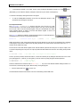
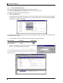
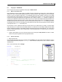
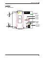
The EDK is equipped with a TWO RED LEDs that may be controlled by a program. LED D1 is connected to the 3664F port 5
bit 7 ( pin 30 on X3:underside of board / X4:topside of board ). LED D2 can be connected to port 5 bit 6 ( Board pin 31 on X3
/ X4 ) or port 8 bit 2 ( pin 19 on X3 / X4 ) by setting jumper J10 ( see Section 2.2.1 ) . For this tutorial we will be using LED
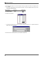
D1. Below is a picture of the EDK3664F showing the LEDs.
EDK3664 Board layout
The numbers next to X2 and X3 are for DIP-42S package. The numbers next to X1 and X4 are for QFP-64 package. For
example Pin 3 on X1 and X2 is connected to Pin 59 on QFP-64 and Pin 1 on DIP-42S.
LED
D1
X3/X4 Pin
30
QFP-64 Pin
27
DIP-42S Pin
23
Pin Function
Port 5 Bit 7 / SCL
This first tutorial example shows how to turn the LED D1 on and off. In the process, you will also learn:
• How to access on-board H8/300HTiny 3664F peripheral control registers.
• How to set up an H8/300HTINY 3664F I/O port for output.
• How to toggle a bit on an H8/300HTINY 3664F I/O port.
• How to download and run a simple program using the HDI debugger.
6
Jan-01
Issue 1.0
EDK3664F Tutorial Manual
1.1.1
SOURCE FILE
Here is a listing of the source file On_Off.c:
#include "iodefine.h"
/* 3664 Onchip peripheral registers */
void main(void);
/* function prototype */
void main(void)
{
IO.PCR5.BYTE = 0x80;
/* Set PORT 5 BIT 7 for output */
while(1)
{
IO.PDR5.BIT.B7 = 0;
IO.PDR5.BIT.B7 = 1;
}
/* turn on LED */
/* turn off LED */
}
To look at the program start Hitachi Embedded Workshop from the Windows Start Menu or from its icon:
• Open a new tutorial workspace from the ‘File | New Workspace…’ menu or
select ‘Create a new project workspace’ if you are presented with the
‘Welcome!’ dialog.
•
Enter a name and path, for example: 3664_TutorialA and C:\…\3664_TutorialA, select “Hitachi H8S, H8/300
Standard” Tool chain and Project type “EDK3664F”.
•
Click OK to start the EDK3664F Project Generator wizard.
•
Select “Tutorial Projects” as the type of project to generate
and then click “Next”.
•
Choose “1. On/Off Tutorial” as the project to generate.
•
Click “Finish” to create the project.
The project generator wizard will create the project OnOff and
insert the necessary files.
Issue 1.0
Jan-01
7
EDK3664F Tutorial Manual
•
If the Workspace window is not visible, show it now by clicking the Workspace window icon on the
toolbar:
(Alternatively you can select the ‘Window | Workspace’ menu item or press ‘Alt-K’ on the keyboard.)
You will see a tree display showing all the files in this project.
•
To view the file On_Off.c double-click on the file in the Workspace window. A new
window will open showing the code above.
File Component Details:
The #include “iodefine.h” include at the start of the file sets up a data
structure that allows us to access the data direction register of the port, and also individual
bits of a byte of data, in this case the data register of the port. See H8/300H TINY 3664F
Series Hardware Manual, for details on how the data direction register is used to set
individual bits of ports for input or output.
The #define statement in iodefine.h assigns the data structure to an absolute address in
the H8/3664 memory space by using a pointer declaration:
#define IO
(*(volatile struct st_io
*)0xFFD0)
/* IO
Address*/
Setting the structure to start at this address allows the structure elements to map onto the corresponding Port 5 peripheral
control registers in the device’s address space. By taking the time to set up this structure, the actual code in the main()
function can be created very simply.
First we set bit 7 in the data direction register, which controls whether a particular bit of the port is for input or output, to one
to set the corresponding bit in the port as an output. By default all data direction bits are set to zero making all the port bits
inputs.
IO.PCR5.BYTE = 0x80;
/* Set PORT 5 BIT 7 for output all others inputs*/
The bit 7 pin of the port itself, and thus the LED D1, can then be controlled just by setting the individual value of bit 7 in the
port’s data register to a 1 (LED off) or a zero (LED on). We can do this very simply using the structure expression:
IO.PDR5.BIT.B7 = 0;
IO.PDR5.BIT.B7 = 1;
/* turn on LED */
/* turn off LED */
These two statements are contained inside a while(1){…} loop, and so will alternate between setting the LED D1 on
and off forever, until we stop the program. Next we will try running the program.
•
Click the Build project icon
or press <F7>.
This will build the first tutorial and create an s-record for downloading onto the 3664 Flash.
8
Jan-01
Issue 1.0
EDK3664F Tutorial Manual
1.1.2
PROGRAMMING THE FLASH ON 3664 USING FDT
Because the EDK3664 has limited RAM and is a single chip microcontroller the HDI monitor code is built with the user’s
code. To debug the user code both user code and the monitor code must be programmed into flash whenever the user code
is built. The HDI monitor library has been built and linked with the user code for this project into an s-record which has the
same name as the project. The s-record is \3664_TutorialA\debug\3664_TutorialA.mot. Until this file is
flashed onto the microcontroller no debug can be performed with HDI.
To flash the EDK3664 first ensure that FDT and the 3664 Flash Kernels Patch have been installed from the EDK3664 CD
see user manual for installation instructions. Run FDT using the start menu item or the icon.
WARNING: Do not create an FDT workspace, we will be using the Quick Programming method!
• Once the ‘Welcome!’ screen for FDT is displayed press CANCEL. DO NOT create a workspace. FDT should now be
running with no open workspace or file.
Now load the s-record created when the project was built
• Load the s-record 3664_TutorialA.mot by selecting the menu item ‘File | Open’ or the icon
Once the s-record has been loaded into FDT it should be visible in the work area
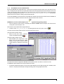
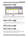
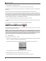
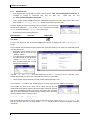
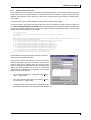
Open the ‘FLASH Controller’ window
• Select the menu item ‘Image | Download
Image’ or the download image icon
Setup the ‘FLASH Controller’ window
• Select H8/3664 as the ‘Target device’, select
BOOT mode and ensure that the ‘Select
Interface’ is set to Direct Connection. Ensure
correct COM Port is selected for the PC being
used.
Once this screen has been configured the EDK3664 must be placed in BOOT mode before a connection is made.
The EDK3664 is placed in BOOT mode using the switches S1 and S2.
•
Connect the supplied serial cable to your PC and the ‘UART’ RS-232 port on the EDK and apply 5V to the EDK’s power
terminals. The green power LED (D5) should light indicating power is being supplied to the board
Issue 1.0
Jan-01
9
EDK3664F Tutorial Manual
•
Press the ‘ARM’ switch S2. The yellow ‘ARMED’ LED D4 will light indicating the EDK
can be placed in BOOT mode.
•
Press the ‘RESET/BOOT’ switch S1. The red ‘BOOT’ LED D3 will light indicating the
EDK is now in BOOT mode. If S1 is pressed again while the yellow ‘ARMED’ LED is lit
the EDK can be taken in and out of BOOT mode and the red ‘BOOT’ LED D3 will turn
on and off to indicate this.
Once both the yellow ‘ARMED’ LED D4 and the red ‘BOOT’ LED D3 are lit FDT can connect
to the EDK and program it with the desired s-record.
•
Press the ‘Connect’ button in the ‘FLASH Controller’ Window of FDT. FDT will connect to the EDK and the FDT output
window will indicate this.
•
Once connected the ‘Download file project_name.mot to device’ button will be available. Press this button and FDT will
download the s-record to the device and the FDT output window will indicate this.
Once downloading of the s-record is complete the EDK can be taken out of BOOT mode and FDT disconnected from the
board
•
Press the ‘RESET/BOOT’ switch S1. The red ‘BOOT’ LED D3 will turn off indicating the EDK is not in BOOT mode.
•
Press the ‘ARM’ switch S2. The yellow ‘ARMED’ LED D4 will turn off and the EDK cannot be put into BOOT mode.
•
Press the ‘Disconnect’ button in the ‘FLASH Controller’ Window of FDT. FDT will disconnect from the EDK.
Now the ‘RESET/BOOT’ switch S1 can be used only as a RESET source to the H8/3664. Before trying to connect HDI to the
EDK ensure the connection with FDT is no longer operational, if it is HDI will not be able to acquire the serial port from the
Windows operating system
•
Ensure the code is running on the EDK by pressing reset button S1 again
1.1.3
CONNECTING HITACHI DEBUGGING INTERFACE - MONITOR
Installed with HEW is the modular Hitachi Debugging Interface (HDI), an embedded monitor kernel programmed onto the
EDK (HDI-m) with the user code allows you to debug the user code running on it using HDI. For more information about the
HDI debugging monitor (HDI-m) on the EDK see the EDK3664 User Manual HDI Section.
•
•
Connect the supplied serial cable to your PC and the ‘UART’ RS-232 port on the EDK and apply 5V to the power
terminals.
Run HDI by clicking on the Launch Debugger icon on the HEW toolbar.
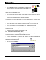
A Select Session dialog should appear as below,
•
10
select a new session on H8/300H Monitor.
Jan-01
Issue 1.0
EDK3664F Tutorial Manual
You should see the window below appear.
Note: The status bar shows the message ‘Link up’ to indicate successful connection to the HDI-M monitor on the
EDK. If the EDK does not link up ensure the Baud rate is set to 19200 and that the correct PC serial port is selected.
1.1.4
RUNNING TUTORIAL A
The executable code for Tutorial A is provided in file
C:\…\3664_TutorialA\debug\3664_TutorialA.abs.
•
To download the code to the EDK, select the ‘File | Load Program…’ menu option in HDI, or click on the Load Program
button in the Toolbar:
Menu Command:
File | Load Program
•
Accelerator
Toolbar Button
none
Once the file has been specified, click on the OK button to perform the download.
‘Downloading…’ should appear in the HDI status bar. If errors occur in downloading these will be displayed on the status bar
too. If errors occur this is an indication that the code programmed onto the chip is not the same as the code being
downloaded onto HDI. On completion of the download a status window should appear similar to the one below:
This information shows that HDI-m has loaded the file and summarises the memory regions used by the program.
Issue 1.0
Jan-01
11
EDK3664F Tutorial Manual
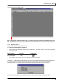
To start executing the program you must set the Program Counter (PC) register to the address of the beginning of the
main() function.
• HDI provides a simple method to see and edit the CPU registers - first open the Register window using one of the
command entry options listed below:
Menu Command:
Accelerator
View | Register Window
Toolbar Button
Ctrl-R
The register window will appear.
•
Use the mouse to position the cursor over the ‘PC’ register value field and double-click on it. A register edit window will
appear, which should be set as below:
The PC will now be set to the main() function, so you can perform a program step.
12
Jan-01
Issue 1.0
EDK3664F Tutorial Manual
•
To verify this open a source code window and choose C:\…\3664_TutorialA\On_Off.c from the file selection dialog.
Menu Command:
View | Program Window
Accelerator
Toolbar Button
Ctrl-K
A window appears showing the C source code with the first line, corresponding to the PC value highlighted.
•
To make the screen layout more readable you might like to “dock” the register window. To do this click on the dock
button in the window’s title bar:
The window will automatically dock to the right-hand side of the HDI main window. To dock to another side, just drag the
window by its title bar, a dotted outline will appear which will “snap” to the sides of the main window. When it snaps where
you want the window, release the mouse button and the window will dock. To undock a window just click the dock button
again.
•
To execute the first line of the program, select the ‘Step Over’ command using one of the methods listed below.
Menu Command:
Accelerator
Run | Step Over
Toolbar Button
F7
•
Repeat the ‘step over’ process for the next line and you will see the LED D1 on the board turn on. Step again and the
LED D1 turns off. Stepping repeatedly will cycle around the while() loop turning the LED D1 on and off.
•
We would like to turn the LED D1 on and off without having to keep stepping in the debugger, you can use the Go
command to do this, try it:
Menu Command:
Run | Go
•
Accelerator
Toolbar Button
F5
You can stop the program running using the Halt command:
Menu Command:
Run | Halt
Accelerator
Toolbar Button
ESC
Did you see what you expected? Did the LED D1 flash on and off, or did it instead just glow dimly?
The LED D1 is actually flashing on and off, but the micro-controller is doing it so fast you cannot actually see it (instead it
looks dim). This is because the processor operates much faster than we can step manually. In order to see it flash at a rate
visible to humans, we need to slow it down using a delay. We will do this in the next tutorial.
Issue 1.0
Jan-01
13
EDK3664F Tutorial Manual
1.2
TUTORIAL B: “FLASHER”
This tutorial shows how to build a program that automatically flashes the EDK’s red LED D1, and how to use HDI-m to
download, run, and modify this program. In the process, you will see how to:
•
•
•
Use header files for declaring data structures.
Use a delay loop to set human-visible delays.
Use HDI-m for examining and debugging a program.
1.2.1
SOURCE FILES
Here is a listing of the source file for Tutorial B:
#include "iodefine.h" /* register definition header file */
void main(void)
{
unsigned short ii=0;
IO.PCR5.BYTE = 0x80; /* Set PORT 5 BIT 7 for output all others inputs*/
while (1)
{
ii++;
if (ii == 30000)
{
IO.PDR5.BIT.B7 = 0;
}
else if (ii == 60000)
{
IO.PDR5.BIT.B7 = 1;
}
}
/* turn on LED */
/* turn off LED */
}
The structure definition and assignment that we did in Tutorial A to make it easy for us to access the on-chip peripheral
control registers has already been done for all the device’s peripheral registers and the code for this is in a header file called
‘iodefine.h’. This file is created when you generate a new project in HEW. So for this tutorial example all we have to do is
include the file in our C file:
#include "iodefine.h" /* register definition header file */
With this file included we can then use any structures or assignments declared in it in our C program. Note that each
separate C file that uses any of these definitions must #include the header file in it.
In the main() function the local variable ii is incremented in an endless while loop and adds delay to the setting and
resetting of the LED D1 bit of port 5. When ii is equal to 30000 the LED D1 is switched on, when ii is equal to 60000 the
LED D1 is switched off. The unsigned short ii has a range of 0 to 65535, so on reaching 65535 it increments back
to 0 thus keeping both if and else if statements valid.
1.2.2
HDI-M LIBRARY FILE INCLUSION
By looking at the menu item ‘Options | Linker | Input’ you can see that the monitor library has been included in this build. The
library is in the project directory and is 3664HDIMLIB.lib. Use of this library is described in the next tutorials and specifically
in Section 3.2.
14
Jan-01
Issue 1.0
EDK3664F Tutorial Manual
1.2.3
BUILDING THE FLASHER PROJECT
This next section will outline how to build a project to run with HDI-M. First start Hitachi Embedded Workshop from its icon or
the Windows Start Menu, the previous workspace will automatically be loaded.
• Create a new workspace as in Tutorial A, but this time call the project “3664_TutorialB” and select “2. Flasher tutorial”
as the project to generate in the Project generator wizard.
•
Click the Build project icon
or press <F7>.
If it is not already open, the output window will open and the progress of the build will be displayed.
You will see a warning from the linker “1210 CANNOT FIND SECTION(C)”, this is not a major problem in this case. Section C
is used to store constant data and an entry has been put in the linker section options list for this section. The linker is
complaining that it cannot find any data for that section, because as this code has no Constants, no constant data is
generated. This will be explained further in Tutorial C Section 2.1.3.
1.2.4
FLASHING TUTORIAL B ONTO THE EDK
The HDI monitor library has been built with the user code for this project into an s-record which has the same name as the
project. The s-record is \3664_TutorialB\debug\3664_TutorialB.mot. Until this file is flashed onto the
microcontroller no debug can be performed with HDI. Ensure that no programs are using the serial port (i.e. the last session
of HDI must be closed) and flash the 3664_TutorialB.mot file onto the EDK using the same method described in
Tutorial A Section 1.1.2. Once programmed ensure that FDT is disconnected from the EDK and proceed to the next section
on debugging the code.
Issue 1.0
Jan-01
15
EDK3664F Tutorial Manual
1.2.5
SETTING AND VIEWING BREAKPOINTS
Now launch the debugger again and this time load the file that we have just built
C:\…\3664_TutorialB\debug\3664_TutorialB.abs the same way as you did in Tutorial A.
Open the program window as before, this time with the file
C:\…\ 3664_TutorialB\Flasher.c.
•
To set the PC register to the start of the program, click on the _main label in the Label column of the Program Window
to position the cursor, right-click to pop up the local menu and select ‘Set PC Here’. The line should then be highlighted
to show that it is at the current PC address.
To check that the program does what we expect, we will first set breakpoints to stop at the line in the code where the port bit
controlling the LED D1 is toggled.
•
To set a breakpoint, open the breakpoint control window using the commands shown below.
Menu Command:
View | Breakpoints
•
Accelerator
Toolbar Button
Ctrl-B
Right-click in the breakpoint window to pop up the local menu, select
the ‘Add…’ item and enter the address shown below:
114
else if (ii == 60000)
Once entered, the break window will show the new breakpoint, and
also the code window will have a black dot next to the line of code
in the BP column.
16
Jan-01
Issue 1.0
EDK3664F Tutorial Manual
If the line you wish to break on is visible in the code window, a quicker way to set breakpoints is to double-click
in the BP column on the same line as the code.
You should see the black dot appear and an entry for that breakpoint appear in the breakpoint window.
If you double-click again you can remove the breakpoint, you should see the black dot in the program window and the entry
in the breakpoint window disappear.
•
Ensure a breakpoint is set on address 0x114
WARNING: The EDK3664 will only allow ONE breakpoint to be assigned at any one time. If a breakpoint is set then
the command ‘Go to Cursor’ will not work as this command uses a temporary breakpoint.
1.2.6
•
RUNNING THE PROGRAM AND HALTING EXECUTION
To run to the breakpoint, select the Go command:
Menu Command:
Run | Go
Accelerator
Toolbar Button
F5
The program stops and the yellow highlight bar will now be placed on the breakpoint in the main function in the code window.
The status bar indicates the cause of the break, i.e. that we have reached the breakpoint:
The highlight bar shows the position in the code corresponding to the value of the program counter (PC) register and
indicates what will be the next instruction to be executed if we Go or Step.
WARNING: For EDK3664 the Breakpoints are controlled though the Address Break Controller. The line of code
where the breakpoint is placed is EXECUTED and the program stops on the next assembly line following the
breakpoint.
•
Open a disassembly window by using the local menu item ‘GO Disassembly’
You will notice that the line where the breakpoint has been placed has been executed and the PC and highlighted line is on
the next line of code in this case at address 0x118 rather than 0x114!
Issue 1.0
Jan-01
17
EDK3664F Tutorial Manual
If you look at the LED D1 on the EDK it should be on.
•
Go again and you should see the LED D1 stay on and the program stop at the breakpoint again.
If you keep issuing the Go command you will see the LED D1 flash once the program is executed to the breakpoint about
60000 times!!.
Now we would like to run the code at full speed and see the delay loops making the flash of the LED D1 visible.
We can temporarily disable a breakpoint by selecting it in the Breakpoint window and choosing ‘Disable’ from the right-mouse
button local menu. If you do this you will see the black dot disappear from the Enable column in the Breakpoint window and
also the corresponding dot disappear from the BP column in the Program window. Alternatively you can double-click on the
dot in the Breakpoint window Enable column to toggle the enabled/disabled state for the breakpoint. Note even though the
breakpoint is disabled it is still valid and so no more breakpoints may be added.
•
Make sure the breakpoint is disabled, and start the program running with the Go command.
You should now see the LED D1 flashing visibly on the EDK and the message on the status bar should read ‘User Program
is Running…’.
So now our program is running at full speed, but how do we stop it? To halt program execution:
Menu Command:
Run | Halt
Accelerator
Toolbar Button
ESC
The program will stop with the highlight bar in the Program window showing the current location and the User Break
message on the status bar ‘Break = User Break’
WARNING: Be very careful when placing breakpoints, always use the ‘Disassembly window’ and be aware of
instruction prefetches after branch instructions. A breakpoint set on a branch will break on the line of code that the
instruction branches to. A breakpoint set on a line of code after a branch may never be triggered because the line of
code may always be prefetched. Try putting a breakpoint at address 0x11a, this will never be triggered because the
compare and branch instructions before the code cause the code at 0x11a to always be prefetched.
1.2.7
VIEWING VARIABLES
We would like to view the value of the ii variable.
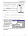
•
Place the cursor in the code window over ii, after a short delay a tool-tip style information box will pop up showing the
value of ii. This gives you a quick way of viewing a variable’s value.
•
Alternatively click to locate the cursor on the variable then use the right mouse button to pop up the local menu:
•
Select the Instant Watch… option, a dialog will open showing you that ii is equal to 0.
This dialog is useful if the variable is more complex e.g. a pointer, array or structure.
•
18
Select the ‘Add Watch’ option and the main Watch window will open showing the count variable.
Jan-01
Issue 1.0
EDK3664F Tutorial Manual
Note that the default display for the variable shows its value in hexadecimal (H’). However, our code test values are decimal
so it would be more useful to be able to view the value of the watched variable in decimal.
•
To change the radix of the watchpoint display, click on the variable name in the Watch window and pop up the local
menu, select Radix | Decimal:
The value in the watch window will then be displayed in decimal. The Watch window will display the current value of ii
whenever the program has stopped.
1.2.8
USING HDI-M TO MODIFY A VARIABLE
•
To see this working, set a breakpoint on the line of code where ii is incremented (ii++;) and Go to this point.
•
In the watch window, place the cursor on the ii variable, and press the right mouse button to show the Watch
window’s local menu again. Select ‘Edit Value’ to display the dialog below:
•
Now change the value of ii to 59999, and run to the next instruction, you should see that the value of ii has been
incremented to 60000. Step to the test:
if (ii == 30000)
•
Step again and you will see that the program steps past to the next if()test as this test is not satisfied.
•
Step again and you will see that the next test is satisfied (we can see in the Watch window that ii does equal 60000)
and so the LED is turned off.
Issue 1.0
Jan-01
19
EDK3664F Tutorial Manual
2. EMBEDDED CODE TUTORIALS
Up to now all of our examples have assumed that we are writing code within the ‘friendly’ environment provided by HDI-M,
and that only the basic features of the H8/300HTINY 3664F are being used. This second set of tutorials provides an
example set of applications to allow you to write code which is intended for execution without HDI-M being present, i.e. code
for a final application.
The tutorials address the following issues:
•
•
•
•
Using the Hitachi Embedded Workshop(HEW) to build a project
Using an example startup code file which allows the static data sections to be initialised, provision is also made for stack
pointer initialisation, hardware setup and exit code.
The use of the on-chip timer module is examined. This highlights the use of the on-chip control registers and in
particular the interrupt mechanism within the EDK standard environment. This includes creation of the interrupt vector
table and the use of in-line hardware control functions to control the CPU from C.
The final tutorial allows the HDI-M monitor in flash to be replaced with a user’s application code - this will then operate
without the overheads (but also the protection) of HDI-M, and represents the final version of an application which would
be used in target user hardware.
Throughout code listings are given, where appropriate, in the text.
20
Jan-01
Issue 1.0
EDK3664F Tutorial Manual
2.1
TUTORIAL C: “STATICS”
The source files for this tutorial are generated in the project “3. Statics tutorial”.
2.1.1
NEED FOR THE STARTUP CODE
Most C applications will have a certain number of variables which are of either global or module scope. These variables are
referred to as ‘static’, as they require statically allocated (i.e. at build time) space. Static variables may be of any valid type
and may, or may not, be given an initial value. In an embedded system the code is resident in some form of non-volatile
memory (ROM, Flash) and the application must boot from an uninitialised state at power-on. In such systems the static data
must be set to its initial values before the user’s application code is called (i.e. before main()executes). In addition it is
common for the application’s data area to be located in some form of memory which requires the system hardware to be
initialised before it can be accessed e.g. RAM. These systems require startup code to perform the initialisation from reset,
and then to pass execution to the user code. If the user’s code should ever return from main() (not really a good idea in
an embedded system), then some valid operation should be performed, rather than randomly executing code which happens
to exist past the call to main() in the startup code.
The information on how to initialise the static areas must be stored in non-volatile memory (i.e. ROM), so that the startup
code knows what to do. However the most desirable situation is one where the user can happily forget about the startup
because initialisation information is automatically created and referenced using the compiler build tools. This is the goal of
tutorial C, to demonstrate that this code has indeed worked. A small example file statics.c is created and then run under HDIM to verify the result.
•
Create a new workspace as we did in Tutorial B, but this time call the project “3664_TutorialC” and select “3. Statics
tutorial” as the project to generate in the Project generator wizard.
2.1.2
STARTUP CODE DETAIL
• Setup the reset vector
The vector table including the reset vector is defined in the file vecttbl.src and its associated include file vect.inc. As HDI-m
is being used the reset vector must point to startup() which is the HDI-m startup function. This is covered in Tutorial E
interrupt tutorial.
Here is a list of the startup code for resetprg.c.
#include
#include
<machine.h>
"stacksct.h"
#pragma entry PowerON_Reset
extern void main(void);
extern void _INITSCT(void);
#pragma section ResetPRG
void PowerON_Reset(void);
void PowerON_Reset(void)
{
set_imask_ccr(0);
_INITSCT();
/*
HardwareSetup();*/
/* Remove the comment when
you use Hardware Setup */
main();
while(1)
sleep();
/* Catch return from main */
}
Issue 1.0
Jan-01
21
EDK3664F Tutorial Manual
The operations to be performed by the startup code are:
•
Unmask all interrupts
is library function used to clear the interrupt mask bit of the system control register CCR.
set_imask_ccr(0)
• Set the stack pointer to a valid address.
The initialisation process can be viewed in the function PowerON_Reset() in the project file resetprg.c. This function is
declared as the entry point of the system using the “entry” #pragma, this tells the compiler to insert assembly code at the
beginning of the function to set up the stack pointer using the section name S and the stack size stored in stacksck.h. For
more details on setting the stack see the Hitachi H8S, H8/300 Series C/C++ Compiler User’s Manual [ADE-702-189].
#pragma entry PowerON_Reset
• Set the static variables with initial values to the correct values.
• Reset all other static variables to 0.
According to the ANSI C language specification all uninitialised static data must be cleared to zero at startup. Any global
variable that has not been given initial value when it is declared can be classed as an uninitialised data variable and should
be initialised to zero. Similarly initialised static variables that have been given initial values when declared must be initialised
at startup with these values. For your C program to be able to manipulate the resultant initialised data it must reside in RAM.
However, the initial values for the data must be stored in non-volatile memory (to survive a power-on reset) and copied to
RAM at startup, thus initialising the data.
Static variable initialisation is done by a library function __INITSCT which is called from resetprg.c. Sections to be initialised
are defined in dbsct.c. If the user creates a data section with a different name from the standard sections then they must be
added to dbsct.c. Memory Sections are described in the 2.1.3.
• Call the hardware initialisation code.
If the comments are removed hardware initialisation function HardwareSetup() is called. It is up to you to define this
function and include it in your project if you need to initialise your hardware
A good example of low level initialisation is SDRAM setup. Most of Hitachi’s microcontrollers have direct interfaces to many
different types of memory, but some of these interfaces have to be setup before the memory can be accessed. The interface
should be setup in HardwareSetup(), before static initialisation so that any static variables within this memory can be
initialised later in the startup code. For H8/3664 there is no external bus to interface so the Hardware setup file could be used
to initialise the microcontroller’s on chip peripherals. This is covered in Tutorial D Timer.
• Call the users main routine.
main() is called.
• If the users code returns, call the exit routine.
Finally the PowerON_Reset() function ends with a sleep() intrinsic function call to put the microcontroller into a
safe state.
WARNING: When using HDI-m the PowerON_Reset() function must always be used. This is explained in
STANDALONE Section 3.2.
22
Jan-01
Issue 1.0
EDK3664F Tutorial Manual
2.1.3
VIEWING THE STATICS
The example C file Statics.c is shown below:
unsigned char string[] = "hello world";
int count;
/* Global variables */
void main (void)
{
int volatile loc;
for (count=0; count<12; count++)
{
/* overwrite the characters in string[] */
string[count] = 'a' + (unsigned char) count;
loc++;
}
}
This file has been built to run with HDI-m. There are three variables in this code, two global and one local. The character
string string[] has an initial value, integer count does not and neither does the local int loc.
By default the sections have the following names.
ANSI C Section
Program
Constants
Initialised Data
Uninitialised Data
Hitachi
Compiler/Linker
section name
P
C
D
B
The uninitialised integer count is in section B (RAM) and is initialised to zero by _INITSCT. The local integer loc is
uninitialised in accordance with the ANSI C specification and has an undetermined initial value.
The code in _INITSCT copies the initial value of string[] in ROM to
RAM. The initial value is in section D (ROM) and is copied to R (RAM),
this can be seen in the Ouput tab of the ‘Options | Linker | Output’ menu
item.
If the user adds their own section names using the #pragma section
statement 4 new sections could be created, for example:
#pragma section ResetPRG
If there is code following this section definition the code will be stored in
a section named PResetPRG CResetPRG DResetPRG and
BResetPRG. depending on the data types shown in the table above.
DResetPRG and BResetPRG must be added to dbsct.c and
RResetPRG must be defined in the section definitions under menu item
‘Options | Linker | Sections’. DResetPRG and RResetPRG must also be
added to the ROM to RAM mapping.
Custom sections are described in more detail in Section STANDALONE 3.2.
NOTE: If a section is defined in the link map (‘Options | Linker | Sections’ menu item) but no data is assigned to it the
linker will issue a warning 1210 Cannot Find Section(name).
Issue 1.0
Jan-01
23
EDK3664F Tutorial Manual
2.1.4
RUNNING THE CODE
•
Now disconnect HDI from the EDK and Flash it with the file C:\…\3664_TutorialC\debug\3664_TutorialC.mot as
described in Tutorial A. Disconnect FDT from the EDK and
restart HDI and load
C:\…\3664_TutorialC\debug\3664_TutorialC.abs
•
Open a program window for Statics.c and place a breakpoint at the first line of code in main(). Place a watch on the
three variables loc, string[] and count using the same method used in Tutorial B.
The watch window should show something similar to the picture. It can be seen from
this that before initialisation loc has no value, as it is a stack based local variable.
count and the character string string[] have random values.
•
Now reset the processor and then Step once.
Menu Command:
Accelerator
Run | Reset
Toolbar Button
-
A source code window will open showing the resetprg.c file with the PC highlight bar in the PowerON_Reset()
function:
This first step will have executed the assembly code that sets up the stack pointer (you can check in the disassembly window
if you want to verify this).
• Step again to set the interrupt mask, the
highlight will now be on the call to the
_INITSCT() function.
• If you Step Over this call while inspecting
the Watch Window you will see that the
variables string[] and count
have now been initialised, with our initial
data and zero respectively.
Now both count and string[] have been initialised but the local loc has not, its value is in fact blank. This is
because local variables only have a valid scope inside their functions i.e. local to them.
•
Let the program continue with the Go command, it will stop at the breakpoint in main().
You can see that loc now has a value, because the PC is now in the scope of the local variable i.e. in its function.
Local variables are stored on the stack and the values that they have are
indeterminate, being whatever happens to be at that location on the stack. Therefore
they need to be initialised manually in the code as the compiler does not initialise
them on the stack, alternatively the STATIC keyword could be used to ensure that
the local variable is stored at a memory location.
int loc=0;
or
static int loc;
Now test the execution of the main code by setting a break after the main() function call in PowerOn_Reset() (line
0x46) and running to this break. The string variable string[] will now contain the sequence ‘abcdefghijkl‘ rather than
‘Hello World‘.
24
Jan-01
Issue 1.0
EDK3664F Tutorial Manual
2.1.5
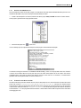
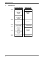
MEMORY MAP FOR EDK3664F WITH HDI-M
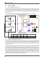
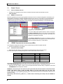
The processor on the EDK is in single chip mode and cannot be changed. This means the chip is in normal mode with onchip ROM(Flash) enabled. The processor can access 64Kbytes of memory space (see H8/300HTINY 3664F Hardware
Manual CPU Section) HDI-M sets up system registers in order to communicate with the user code, these peripheral registers
should not be changed once HDI-M is running. The Peripherals used by HDI-M are:
1. SCI3 for serial communications
2. Address Break controller for stepping and breakpoint control
3. NMI control for Flash Programming
EDK H8\3664F TINY Memory Map with HDI-m
H’0000
Vector area
H’0034
HDI-Monitor code.
(Relocatable)
6Kbytes
H’17F6
Free FLASH.
(For User Code)
26Kbytes
H’7FFF
Unpopulated
H’F780
Flash work Area And
User RAM 1Kbytes
H’FB80
Internal RAM
For User code
778Bytes
H’FE8A
Internal RAM
For Monitor Work Area
(Relocatable)
245Bytes
H’FF80
Internal Registers
H’FFFF
Issue 1.0
Jan-01
25
EDK3664F Tutorial Manual
2.2
TUTORIAL D: “TIMER”
2.2.1
SETTING THE LED D2 TO THE CORRECT PORT
The EDK is equipped with a TWO RED LEDs that may be controlled by a program. LED D1 is connected to the 3664F port 5
bit 7 ( pin 30 on X3:underside of board / X4:topside of board ). LED D2 can be connected to port 5 bit 6 ( Board pin 31 on X3
/ X4 ) or port 8 bit 2 ( pin 19 on X3 / X4 ) by setting jumper J10. Below is a description of jumper, LED and pin positions. A
table of LED to port, bit and board pin is also below. For a more detailed description of the pin out of the EDK refer to the
EDK3664F User manual.
For this tutorial we will be using LED D2 connected to port 8 bit 2 (X3/X4 PIN 19) which is also a timer output pin.
• Ensure J10 is connected with a jumper block across 2-3 as shown below.
Jumper 10 with NO Block Fitted.
:Illegal setting
Jumper 10 with Block Fitted 1-2
:LED D2 connected to Port 5 Bit 6
Jumper 10 with Block Fitted 2-3
:LED D2 connected to Port 8 Bit 2
EDK3664 Board layout
LED
D2
D2
2.2.2
J10 Block
Position
1-2
2-3
X3/X4
Pin
31
19
QFP-64
Pin
26
38
DIP-42S
Pin
22
30
Pin Function
Port 5 Bit 6 / SDA
Port 8 Bit 2 / FTIOB
ACCESSING THE CONTROL AND STATUS REGISTERS
The H8/300HTINY 3664F microcontroller contains a lot more than simply a CPU. A whole host of peripherals are available
to you for use in a target application. Each peripheral module has a set of control and status registers, which act as the
interface to the CPU, many peripherals also have pins associated with them, which act as the interface to the outside world.
Each peripheral can signal a change in its status by setting bits in one of its registers, or by sending an interrupt to the CPU,
prompting immediate action.
The control and status registers of the peripheral modules are memory mapped, each one having a unique address at the
top of the address space. Registers vary in type, from byte wide to long word wide and from read/write to read or write only.
To allow simple access to the registers the flexible casting feature of C may be used. As we saw in Tutorials A and B, a
symbol can be defined which corresponds to the access inside the address of the given register. This requires the address,
which is a constant integer value, to be treated as an address reference (i.e. a pointer), and then pointer indirection to be
used to access the contents of the address. To further complicate matters, the entire construct must be declared as ‘volatile’
to stop the C compiler from optimising away accesses to the register. This is because the registers may be modified by
some operation other than one performed by the CPU, and thus the compiler can have no visibility of this. Optimising
compilers often remove accesses to what appears to be redundant information - this must be stopped in the case of
peripheral control and status registers, hence the use of the ‘volatile’ keyword.
26
Jan-01
Issue 1.0
EDK3664F Tutorial Manual
If you remember in Tutorial A we defined the i/o registers as below:
#define IO
(*(volatile struct st_io
*)0xFFD0) /* IO
Address*/
and in Tutorial B we learned that to simplify the construction of user code the header file iodefine.h has been created which
contains all of the on-chip peripheral registers for the H8/300HTINY 3664F.
The file iodefine.h follows the naming scheme used in the hardware manual. The name of the structure corresponds to that
of the peripheral module, and the structure elements to the control registers and even individual bits in those registers.
Note: The addresses used in the header file are those defined in the hardware manual for the device operating in
64kbyte mode - if an address greater than 64K Bytes is offered to the CPU, the most significant bits are ignored.
Thus there is no need to re-write the file for use in 64KByte systems.
2.2.3
THE TIMER PROGRAM
The Tutorial project ‘4. Timer Tutorial’ contains the source files for this tutorial, the main module Timer.c is listed below. The
application flashes the LED D2 using one of the on-chip 16 bit timer modules, Timer W, instead of by software. We will use
the timer to output a PWM square wave signal on timer output TIOB which is multiplexed with Port 8 Bit 2 of the device, to
which the LED D2 is connected via J10 2-3 on the EDK. Port 8 and the timer output TIOB both share this pin, but cannot use
it at the same time. The cycle period for the waveform is set by the value in the timer’s TGRA register and the duty cycle is
set by the value in the TGRB register.
When the timer is enabled it will start counting up. When the value in the TCNT register matches the value in the TGRB
register the output of the pin will go to 1 turning the LED D2 off, and the counter will continue to increment. When the value in
the TCNT register matches the value in the TGRA register the TCNT register will be reset to zero, causing the cycle to reset
and the output of the pin to be cleared turning the LED D2 on.
•
Generate a new tutorial project as done in previous tutorials but this time select ‘4. Timer Tutorial’ and call it
3664_TutorialD. The following workspace view should be seen.
•
View the file Timer.c by double clicking on it in the workspace window
Issue 1.0
Jan-01
27
EDK3664F Tutorial Manual
#include "iodefine.h"
/* Define constants for peripheral register vaules */
#define TCR_CCLR
1
/* Set TCNT cleared by TGRA match */
#define TCR_CKS
3
/* Clock source internal/8 */
#define TMR_PWMB
1
/* PWM mode in channel B */
#define TCR_TOB
0
/* output 0 on TIOB at start */
void main(void)
{
volatile unsigned short duty;
TMRW.GRB = duty = 0x7fff;
TMRW.TMR.BIT.CTS = 1;
/* Set duty of LED 50% by GRB */
/* Start Timer W */
while(1)
TMRW.GRB = duty;
/* Change duty cycle */
}
void HardwareSetup(void)
{
MSTCR1.BIT.MSTTW = 0;
TMRW.TMR.BIT.CTS = 0;
TMRW.TCR.BIT.CCLR = TCR_CCLR;
TMRW.TCR.BIT.CKS = TCR_CKS;
TMRW.TMR.BIT.PWMB = TMR_PWMB;
TMRW.TCR.BIT.TOB = TCR_TOB;
TMRW.GRA = 0xffff;
}
•
•
•
•
•
RUNNING TIMER
Build the code generated from the project generator.
Now disconnect HDI from the EDK and Flash it with the file C:\…\3664_TutorialD\debug\3664_TutorialD.mot as
described in Tutorial A. Disconnect FDT from the EDK and
restart HDI and load
C:\…\3664_TutorialD\debug\3664_TutorialD.abs
Open a code window with Timer.c and set a breakpoint at the start of main().
Reset Go and the program should stop at the breakpoint.
Menu Command:
Run | Reset Go
•
•
•
•
•
Accelerator
Toolbar Button
Shift-F5
Step over the instruction to set the duty cycle
Step over the instruction to start the timer, you should see the LED D2 start flashing with a duty cycle of 50%.
Remove the breakpoint on main()
Set a breakpoint in the while() loop where the duty duty cycle is changed and Go to the breakpoint. (Remember to
check if the instruction will break the process)
Open a local watch window , you can see the value of the variable duty.
Menu Command:
Accelerator
View | Locals
Ctrl-Shift-W
28
Enable TimerW module */
Timer off */
TCNT clear on GRA match */
Clock = phi/8*/
PWM mode for channel B */
initial output is 0 */
Set cycle period by GRA */
The function HardwareSetup() sets up the control registers in the timer module. In order for it to be called we
must ensure the function is called at the start of resetprg.c.
resetprg.c then calls main() in which the duty cycle register is set up and the timer started.
The program then goes into a loop setting the duty cycle (this is so that we can easily modify the value).
2.2.4
•
•
/*
/*
/*
/*
/*
/*
/*
Toolbar Button
Jan-01
Issue 1.0
EDK3664F Tutorial Manual
Now you can modify the duty value in the Local watch window by doubleclicking on the value field in the window, try a new value of H’1fff.
•
Go again to write the value into the TGRB register and you will see
the duty cycle of the LED flash has changed on EDK. Try different
duty cycle values and see what effect it has on the LED’s flashing.
2.2.5
VARIATIONS
You could try changing the period value in the TGRA register to change the cycle time for the LED D2 flashing or modify the
program to vary the duty cycle and create different PWM patterns.
Issue 1.0
Jan-01
29
EDK3664F Tutorial Manual
2.3
TUTORIAL E: “INTERRUPT”
2.3.1
INTERRUPTS ON THE H8/300HTINY 3664F
In most user applications the rapid response of the system to external stimuli is essential, in such systems the CPU must be
informed of the change in the system status immediately. To rely on polled tests of the various peripheral control registers
represents a large CPU overhead. The H8/300H TINY series of microcontrollers all support a wide range of on-chip
peripherals; each being capable of generating at least one CPU interrupt. In addition the CPU may be signalled from external
devices using the NMI or one of the IRQ interrupt signals. In this tutorial we will use the TGRB compare/match interrupt of the
PWM Timer W to vary the duty cycle of the flashing LED D2.
The H8/300H TINY architecture provides direct hardware support for interrupts, via the interrupt controller. Each interrupt
source is allocated a special vector address. The vector address is used to store the address of the interrupt service routine
(ISR) which is to be executed when the relevant interrupt is accepted. The interrupt controller tests the priority level of an
incoming interrupt against the priority level that the CPU will currently accept. If the incoming interrupt is higher than the
current CPU interrupt mask level (stored in the condition code register), then interrupt processing begins. The program
counter (PC) and the condition code register (CCR) are stacked, and the PC set to the value contained in the relevant vector
address. Execution then continues from the new PC value. The ISR should be terminated with a return from exception (RTE)
instruction to ensure that the PC and CCR are correctly restored on exit.
In this H8/300H Tiny we can only use interrupt mode 0. This means that the I bit in the CCR is the interrupt mask bit. If I is set
to 0 interrupts will be enabled, i.e. not masked. See the H8/3664F Hardware Manual Interrupt Section for more information
on interrupt control
2.3.2
CREATION OF AN ISR IN C
It is often desirable to write all your application code in C, where possible. The Hitachi tools support extensions to the ANSI C
language to allow interrupt service routines (ISR) to be written. As mentioned above an ISR is distinguished from a normal
function by the fact that it is terminated using a RTE instruction. However, this is not the only difference. ISRs are by nature
asynchronous and thus you cannot rely on the state of the registers on entry to the function. In addition the ISR must
preserve the state of all registers, as there is no way of telling which registers were currently in use by the CPU when the
exception occurred.
You also need to create an entry in the vector table that gives the address of the ISR for the given interrupt. Each vector is
located at a fixed address, so care must be taken to place it correctly. To define a function as an ISR, simply precede it by
the following form of statement:
#pragma interrupt (INT_TMW)
This instructs the compiler to treat the function INT_TMW, when it is defined in the source code as an ISR, and hence to
preserve the register values, and to terminate with a RTE instruction. When the interrupt occurs the corresponding ISR
function address is fetched from the vector table and the program will jump to that address. Therefore the address of the
INT_TMW ISR needs to be stored in the correct place in the vector table. When you create a new project in HEW, several
files defining the vector table and ISRs are created:
vecttbl.c
vect.h
intprg.c
- actually defines the vector table itself and the vector entries
- declares the ISR function names as external symbols
- a default ISR function for all interrupts not used by HDI-m or the User’s Code (a ‘catch-all’)
An added complication when using HDI-M is that the vector table is located from address H’0, which is in the Flash ROM
area used by HDI-m and the user’s code. To allow us to develop with interrupts, the HDI-monitor must be built with the user
code and the power on reset vector must point to HDI-m code. HDI-m also uses the serial and address break interrupts so
these cannot be used if HDI-m is built with the user code
Issue 1.0
Jan-01
31
EDK3664F Tutorial Manual
2.3.3
•
INTERRUPTS AND HDI-M
Generate a new tutorial project as done in previous tutorials but this time select ‘5. Interrupt Tutorial’ and call it
3664_TutorialE. The following workspace view should be seen.
Vecttbl.c actually defines the vector table itself and creates a section named DVECTTBL
which contains the power on reset function vector and also a section named DINTTBL which
contains the vector entries for all interrupts available on the H8/3664F. As this project has
been built for use with HDI-m the Reset vector in DVECTTBL points to the power on reset
vector for HDI-m.
If HDI-m is to be used this power on reset vector must always be used.
-Power on reset vector when using HDI-m is startup().
Within the interrupt table DINTTBL there are 3 interrupts that cannot be changed if operation
with HDI-m is desired. These vectors are:
-NMI interrupt NMIcapture() for flash programming control
-SCI3 interrupt SCIint() for communications between the PC and the EDK
-UBC interrupt UBCint() for breakpoint control.
If any of these interrupt functions are omitted from the interrupt table HDI-m will not operate correctly.
All other interrupts in this table are serviced by ‘catch all’ functions defined in intprg.c. All the functions are blank except one,
the timer interrupt INT_TMW() is commented out. This is the interrupt routing for the timer used in this tutorial. The ISR
INT_TMW() can be found in Interrupt.c.
If you want to add your own interrupt functions it is advisable to keep the same names already in the tables and simply
comment out the ‘catch all’ function in intprg.c and write another elsewhere. Always remember to use the following compiler
syntax when writing an interrupt routine.
#pragma interrupt (interrupt name)
Here is the code listing for intprg.c
#pragma section IntPRG
void Dummy(void){;}
/* void NMIcapture(void){;}
void INT_TRAP0(void){;}
void INT_TRAP1(void){;}
void INT_TRAP2(void){;}
void INT_TRAP3(void){;}
/* void UBCint(void){;}
void INT_SDT(void){;}
void INT_IRQ0(void){;}
void INT_IRQ1(void){;}
void INT_IRQ2(void){;}
void INT_IRQ3(void){;}
void INT_WKP5(void){;}
void INT_TMAOVF(void){;}
/* dummy*/
/* void INT_TMW(void){;}
void INT_TMV(void){;}
/* void SCIint(void){;}
void INT_I2C(void){;}
void INT_ADEND(void){;}
32
Monitor NMI capture */
Monitor address break interrupt */
Used in tutorial E main() function */
Monitor serial port interrupt */
Jan-01
Issue 1.0
EDK3664F Tutorial Manual
2.3.4
UNDERSTANDING THE INTERRUPTS TUTORIAL
The file Interrupt.c contains the source for the tutorial:
#include <machine.h> /* So that we can use language extensions for embedded systems */
#include "iodefine.h"
/* Define constants for peripheral register vaules */
#define TCR_CCLR
/* Set TCNT cleared by TGRA match */
#define TCR_CKEG
/* Default clock edge */
#define TCR_TPSC
/* Clock source internal/256 */
#define TCR_TOB
/* Set pin ouput modes: TIOB */
/* Function Prototypes */
void main(void);
void HardwareSetup(void);
#pragma interrupt (INT_TMW)
void main(void)
{
unsigned short duty;
TMRW.GRB= duty = 0x7fff;
TMRW.TMR.BIT.CTS = 1;
/* Set duty of LED 50% by TGRB */
/* Start Channel 1 */
while(1);
/* Loop forever */
}
void HardwareSetup(void)
{
set_imask_ccr(0);
MSTCR1.BIT.MSTTW = 0;
TMRW.TMR.BIT.CTS = 0;
/* Enable interrupts to CPU */
/* Enable TimerW module */
/* Timer off */
TMRW.TIER.BYTE &= 0x00;
TMRW.TSR.BYTE &= 0x00;
/* dissable all interrupts */
/* Clear any pending interrupts */
TMRW.TCR.BIT.CCLR = TCR_CCLR;
TMRW.TCR.BIT.CKS = TCR_CKS;
TMRW.TMR.BIT.PWMB = TMR_PWMB;
TMRW.TCR.BIT.TOB = TCR_TOB;
TMRW.GRA = 0xffff;
TMRW.TIER.BIT.OVIE = 0;
TMRW.TIER.BIT.IMIEB = 1;
/*
/*
/*
/*
/*
/*
/*
TCNT clear on GRA match */
Clock = phi/8*/
PWM mode for channel B */
initial output is 0 */
Set cycle period by GRA */
Disable the OVERFLOW interrupt */
Enable the GRB Match interrupt */
}
void INT_TMW(void)
{
TMRW.TSR.BIT.IMFB &= 0;
TMRW.GRB -= 0x400;
}
/* clear B compare/match bit */
/* Decrement duty value by 400 */
The main function is very similar to the main function from Tutorial D. Because the ISR changes the duty value we do not
need to do this in the main and so it just sits in a while () loop.
The INT_TMW(void) function is the interrupt service routine. This corresponds to the symbol entry in the vector table
definition in vecttbl.c. The first line clears the timer’s compare/match interrupt bit, if the interrupt is not cleared, another
interrupt will immediately be generated on return from the ISR.
The second line in the ISR decrements the duty value in the TGRB register to shorten the ‘off’ time of the LED, when
it is decremented past 0 the value in the register will underflow and start again at a high value i.e. with a short pulse
on the LED. Note we decrement the value rather than increment it, because if we incremented then very shortly after
returning from the interrupt, we would get a compare/match on this larger value (as the timer is still counting) rather
than waiting until another complete cycle period has been completed.
The startup function HardwareSetup()has been increased to include an additional line of code to enable the Timer
module channel B compare/match interrupt:
TMRW.TIER.BIT.IMIEB = 1;
/* Enable the GRB Match interrupt */
This causes an interrupt to occur whenever the value in the TCNT register matches that in the TGRB register. The special
function set_imask_ccr(0) is added, this is an in-line function to insert an instruction to change the CCR values and unmask
Issue 1.0
Jan-01
33
EDK3664F Tutorial Manual
the interrupts, in order to use this special function we have to include the header file machine.h. This contains a number of
functions definitions to allow access to CPU operations like accessing the condition code register (CCR) and using specific
instructions e.g. trapa, sleep, movfpe, eepmov, mac, rotlw, dsub, nop. These functions may be used in an application to gain
access to the CPU, they should be used with care as they directly control the underlying hardware and are not subject to
checking by the compiler. For more information on these function see the Hitachi H8S, H8/300 Series C/C++ Compiler User’s
Manual [ADE-702-189].
2.3.5
•
•
•
VIEWING AND RUNNING THE APPLICATION
Select the project 3664_TutorialE and execute a build to create the debug absolute load file, and an S-record to
download to flash using FDT.
Now disconnect HDI from the EDK and Flash it with the file C:\…\3664_TutorialE\debug\3664_TutorialE.mot as
described in Tutorial A. Disconnect FDT from the EDK and
restart HDI and load
C:\…\3664_TutorialE\debug\3664_TutorialE.abs
Open a code window with the file interrupt.c and set a breakpoint at the following line in the ISR INT_TMW:
TMRW.GRB -= 0x400;
•
/* Decrement duty value by 1000 */
Open an I/O register window. It is H83664.io located in the HDI directory. Install it using menu item ‘Setup | Configure
Platform’
Menu Command:
Accelerator
View | I/OArea
Toolbar Button
Ctrl-I
This window lists all of the on-chip peripheral modules, you can expand the module name to show its registers by doubleclicking on the module name. Expand the W_16_Bit_Free_Running_Timer module. You can see the duty cycle value in the
GRB register.
•
Reset Go and the program should stop at the
breakpoint.
You should see the GRB updated with the initial duty
value H’7fff and the LED start flashing with a duty cycle
of 50%.
•
Run to the breakpoint again.
You should see the GRB value decrement by H’400,
continue running and stopping at the breakpoint. You
can see the duty value change and the corresponding flash period of the LED also change. Note that when the program is
stopped the duty value does not change even though the LED continues to flash and compare/match occurs. Although this
does in fact cause an interrupt request, HDI masks interrupts while the program is stopped.
•
Remove the breakpoint and Go.
You cannot see the TGR1B value decrement while the program is running, however you can see the duty value of the LED
flash change.
WARNING: To use this I/O window HDI-m must read a mode bit at address H’FFF1. This is the address for the
SYSCR2 register which controls the subactive clock frequency. A 1 must be written to this register in order for the
I/O window to be used and so the subactive clock cannot be /8.
2.3.6
VARIATIONS
Once interrupts have been mastered programming for real-time applications becomes much simpler. In addition the removal
of polled loops enables many tasks to be performed, seemingly at the same time. In tutorial E_Interrupt the main program
does nothing as it just sits in a while() loop, you could try performing some useful operation in this loop Alternatively you
could try using some of the other on-chip modules. See the H8S hardware users manual for more information on them.
34
Jan-01
Issue 1.0
EDK3664F Tutorial Manual
2.4
TUTORIAL F: “LONER”
The final example simply takes the code from Tutorial E and makes it run on the EDK without HDI-M. The aim of this
example is to show that an application can be created using these tools which will be capable of running ‘stand-alone’. The
majority of the work has already been done - the startup code was created in Tutorial C, the peripheral register address
header file was used in Tutorials B & D and the interrupt vector table was explained in Tutorial E. This example uses similar
source files that were used in Tutorial E. The main difference is that since HDI-m will not be resident, a real power on reset
vector must be created and not one that calls HDI-m initialisation function startup(). Tutorial F is a version of Tutorial E
Interrupt that will run from Flash without HDI-m. Also since HDI is no longer using the UART serial interface this is now
available to our application, we will use it to write a sign on banner and echo back characters from an external terminal (in
this case Hyperterminal).
2.4.1
•
•
CREATION OF A VECTOR TABLE IN C WITHOUT HDI-M
Generate a new tutorial project as done in previous tutorials but this time select ‘6. Loner Tutorial’ and call it
3664_TutorialF.
If you now look at the linker section map in HEW (menu item
‘Options | Linker | Section’ ) you can see that the reset vector
section DVECTTBL is placed at H’0 followed by the interrupt
vector section DINTTBL as in previous tutorials.
The interrupt vector table must be located at this address to ensure
startup code is executed first on reset. The startup code in file
resetprg.c does not change but the power on reset vector points to
PowerOn_Reset()rather than the HDI-m initialisation function
startup().
The vector table definition in vecttblt.c does not contain any of the
HDI-m interrupts described in Section 2.3.3. instead these peripherals
are available to the user.
Note also that in the menu item ’Options | Linker | Input’ there is NO
inclusion of the HDI-m library file.
2.4.2
LOW LEVEL INITIALISATION
As we saw in the previous tutorials, low level initialisation occurs before the user’s code is called in order to set up the bus
protocol and essential peripherals. Since we are running stand-alone we cannot rely on HDI to initialise the EDK environment
for us. Therefore we must do it ourselves in Hardware_setup() which is shown in the source below from Loner.c.
void HardwareSetup(void)
{
set_imask_ccr(0);
MSTCR1.BIT.MSTTW = 0;
TMRW.TMR.BIT.CTS = 0;
TMRW.TIER.BYTE &= 0x00;
TMRW.TSR.BYTE &= 0x00;
/*
/*
/*
/*
/*
Enable interrupts to CPU */
Enable TimerW module */
Timer off */
dissable all interrupts */
Clear any pending interrupts */
TMRW.TCR.BIT.CCLR = TCR_CCLR;
TMRW.TCR.BIT.CKS = TCR_CKS;
TMRW.TMR.BIT.PWMB = TMR_PWMB;
TMRW.TCR.BIT.TOB = TCR_TOB;
/*
/*
/*
/*
TCNT clear on GRA match */
Clock = phi/8*/
PWM mode for channel B */
initial output is 0 */
TMRW.GRA = 0xffff;
TMRW.TIER.BIT.OVIE = 0;
TMRW.TIER.BIT.IMIEB = 1;
/* Set cycle period ~1s by GRA */
/* Disable the OVERFLOW interrupt */
/* Enable the GRB Match interrupt */
/* Serial Port 3 Setup */
IO.PMR1.BIT.TXD = 1;
InitSCI3(SCI_Init_Data);
/* Enable SCI3 TX out */
/* initialise serial port */
}
Most of this file is identical to Tutorial E except for the initialisation of the serial port SCI3. This function is described in
Section 2.4.4.
Issue 1.0
Jan-01
35
EDK3664F Tutorial Manual
2.4.3
THE MAIN() FUNCTION
The main() function in is displayed below:
#include <machine.h> /* So that we can use language extensions for embedded systems */
#include "iodefine.h"
#include "SCI3.h"
/* Define constants for peripheral register values */
#define TCR_CCLR
1
/* Set TCNT cleared by TGRA match */
#define TCR_CKS
3
/* Clock source internal/8 */
#define TMR_PWMB
1
/* PWM mode in channel B */
#define TCR_TOB
0
/* output 0 on TIOB at start */
/* SCI Initialisation data structure */
struct SCI_Init_Params SCI_Init_Data={B9600,P_NONE,1,8};
/* Function Prototypes */
void main(void);
void HardwareSetup(void);
#pragma interrupt (INT_TMW)
void main(void)
{
volatile unsigned short duty;
TMRW.GRB = duty = 0x7FFF;
TMRW.TMR.BIT.CTS = 1;
/* Set duty cycle at 50% in GRB */
/* Start the timer */
PutStr((unsigned char *)"\r\nEDK3664F Demo serial output\r\n");
while(1)
{
PutChar(GetChar());
}
}
void INT_TMW(void)
{
TMRW.TSR.BIT.IMFB &= 0;
TMRW.GRB -= 0x400;
}
/* Clear the interrupt */
/* Decrement duty cycle by 0x400 */
This function is much like Tutorial E’s main() function. Three serial functions have been added, one to print out a text
string and the others to echo any characters received by the serial port input in the while statement. The timer interrupt also
remains unchanged.
2.4.4
THE SERIAL I/O FUNCTIONS
SCI3.c and SCI3.h are the files containing the four serial functions shown in the table below.
Function
Return
Arguments
InitSCI3
unsigned char
struct
SCI_Init_Params
GetChar
unsigned char
void
PutChar
void
unsigned char
PutStr
void
unsigned char *
Description
Initialises serial port using data
in structure and returns error
flags
Returns a character received by
SCI3
Transmits a character
Transmits a string of characters
(NULL terminated)
This is example code for control of the SCI3 port. The initialisation function takes a structure
containing four variables set in SCI_Init_Data:
struct SCI_Init_Params
{
unsigned char Baud;
unsigned char Parity;
unsigned char Stops;
unsigned char Length;
};
/*
/*
/*
/*
baud rate register value BRR */
Parity P_NONE, P_EVEN, P_ODD */
Number of stop bits 1,2 */
Length of byte transmitted 7,8 */
struct SCI_Init_Params SCI_Init_Data={B9600,P_NONE,1,8};
The baud rate can be either B9600 for 9600 baud or B19200 for 19200 baud.
36
Jan-01
Issue 1.0
EDK3664F Tutorial Manual
2.4.5
LINKING FOR STAND-ALONE CODE
For an application to exist successfully in a stand-alone environment like the EDK, it must be able to stand the removal of
power from the system and initialise itself from a subsequent Power-On reset condition. To achieve this the parts of the
application which setup the system, including all of the code and constant sections must be placed non-volatile memory,
such as Flash.
In order to be able to store and modify variables and data structures, these must exist in RAM.
To allow the system to start correctly the stack will be placed in the on-chip. Below is the linker map file for Tutorial F in
C:\…\3664_TutorialF\debug\3664_TutorialF.H8L, this file lists information about how the linker has built the application and
where it has located the program sections according to the addresses defined in the HEW linker options. You can see that
the data sections have been placed in on-chip RAM.
ent _PowerON_Reset
ro (D,R)
p "c:\hew\3664_TutorialF\3664_TutorialF\Release\3664_TutorialF.map"
nooptimize
st
DVECTTBL,DINTTBL(00),PIntPRG,PResetPRG(034),P,C,D,$ABS8D,$ABS16D,C$DSEC,C$BSEC(0100),B,$AB
S8B,$ABS16B,R,$ABS8R,$ABS16R,S(0FB80)
o "c:\hew\3664_TutorialF\3664_TutorialF\Release\3664_TutorialF.abs"
i "c:\hew\3664_TutorialF\3664_TutorialF\Release\dbsct.obj"
i "c:\hew\3664_TutorialF\3664_TutorialF\Release\sbrk.obj"
i "c:\hew\3664_TutorialF\3664_TutorialF\Release\vecttbl.obj"
i "c:\hew\3664_TutorialF\3664_TutorialF\Release\resetprg.obj"
i "c:\hew\3664_TutorialF\3664_TutorialF\Release\Loner.obj"
i "c:\hew\3664_TutorialF\3664_TutorialF\Release\intprg.obj"
i "c:\hew\3664_TutorialF\3664_TutorialF\Release\SCI3.obj"
lib "c:\hew\tools\hitachi\h8\3_0a_0\lib\c38hn.lib"
lib "c:\hew\tools\hitachi\h8\3_0a_0\lib\ec2hn.lib"
EXI
Another difference in linking compared with Tutorial E concerns the
output format of the absolute load module.
Since we wish to program the absolute file into the Flash memory
rather than debugging it with HDI-m, we want an S-Record format
output file rather than a SYSROF debug file, the build process
includes a final build phase that creates a .mot s-record file from the
.abs file. Also debug information is of no use to us, by default the
output format for the “Release” build configuration is to not include
debug information in the output file.
•
You can inspect these options in the Ouput tab of the ‘Options |
Linker…’ dialog in HEW.
•
The s-record final build phase setup can be viewed in ‘Options |
S-Type Converter…’ dialog in HEW.
•
Loading the built file into the Flash device using Hitachi’s Flash
Development Toolkit (FDT) as discussed in the Tutorial A Section 1.1.2.
Issue 1.0
Jan-01
37
EDK3664F Tutorial Manual
2.4.6
•
RUNNING THE CODE
Ensure that FDT is disconnected from the EDK and jumper J10 is fitted with a
block connecting Pins 2-3. Press the reset button S1 on the EDK .
This will reinitialise the H8/300HTINY 3664F into normal execution mode. An RS-232
cable may then be connected to the ‘UART’ port of the EDK3664F. The LED should start
to flash with a decreasing duty.
To verify that the character echo code is functioning as previously described in this
tutorial:
•
Start a terminal emulation program (such as Hyperterminal)
•
Connect to the EDK with the correct protocol settings set in Loner.c, the structure struct SCI_Init_Params
SCI_Init_Data={B9600,P_NONE,1,8}; in this case 9600 baud, 8 bit, no parity, 1 stop.
•
On pressing reset button S1 the RED LED D2 should start to flash with the varying duty cycle, indicating correct
operation of the interrupt code and you should see the sign on banner.
•
Characters typed on the keyboard should be echoed back in the terminal window.
2.4.7
VARIATIONS
Now that successful programming of the on-chip FLASH has been completed, it is possible to program the H8/300HTINY
3664F with any application.
38
Jan-01
Issue 1.0
EDK3664F Tutorial Manual
3. NORMAL PROJECT
The EDK3664 Project generator comes with a ‘Normal’ project generater as well as the ‘Tutorial’ and ‘Completed’ project
generator. This section of the tutorial manual explains this function of the Normal Project and the 2 build configurations. One
build configuration is ‘Debug’ which provides an empty project which is already linked to HDI-m Library code enabling the
user code to run with HDI through the serial port SCI3. The other configuration is ‘Release’ which provides an empty project
without HDI-m code for standalone operation on the EDK, much like Tutorial F.
Issue 1.0
Jan-01
39
EDK3664F Tutorial Manual
3.1
‘NORMAL’ PROJECT
3.1.1
CREATING THE NORMAL PROJECT
•
Generate a new Workspace as done in previous tutorials but this time select ‘Normal Project’ and call it
3664_Standalone.
3.1.2
HEW BUILD CONFIGURATIONS
All the files generated by the Normal project generation wizard are common to both build configurations. HEW allows you to
define different configurations for building executable modules from the same set of source files in a project. Each different
configuration may have different compiler, assembler and linker options and may exclude files from the build. When you
create the Normal project, two configurations ‘Debug’ and ‘Release’ are created automatically. You can select the current
configuration from the standard tool bar:
If you use the EDK project generator wizard to create a new project,
the Debug configuration will set up the linker to place the HDI-m
Library file and its associated setup in the code, so that HDI-m can
download your application to the board.
In the Release configuration the sections are defined to create an
absolute module that you can program into the Flash ROM of the
device for standalone operation (i.e. without HDI-m).
3.2
‘DEBUG’ CONFIGURATION FOR OPERATION WITH HDI-M
This configuration will generate a standard s-record for downloading to the EDK for operation with HDI.
• Ensure the Configuration is set to Debug
3.2.1
LINKER SETUP AND SECTION MAP
• Select the menu item ‘Options | Linker | Sections’ and inspect the linker section map shown above:
The Linker section map for the ‘Debug’ Configuration contains 5 extra section names for HDI-m:
Section Name
Pmon
Cmon
Bmon
MONSTACK
S_TOP
Description
HDI-m Code
HDI-m Constants
HDI-m Uninitialised Data
HDI-m Stack pointer
User initial stack pointer
Address
Location
Flash
Flash
RAM
RAM
RAM
Size
6010 bytes
72 bytes
111 bytes
132 bytes
see stacksct.h
When these section are linked with the code care must be taken that they are all in valid memory locations. Check the link
map file 3664_STANDALONE.map to ensure this is the case and check with Section 4.4 H8/3664 Memory Map.
• Select the menu item ‘Options | Linker | Input’ and inspect the libraries built with ‘Debug’ configuration. Ensure that
3664HDIMLIB.lib HDI-m Library file is included
WARNING: S_TOP is set by the user code but it must be placed after the user stack section S in the linker sections
window. This Section name is used by HDI-m Library to set the reset stack S for the user code.
Power_ONReset() must always be the name of the users startup function and it must always be where the user
stack is set using #pragma entry PowerON_Reset
HDI-m Library uses the Power_ONReset() function name in referencing user startup code, this CANNOT be
changed.
40
Jan-01
Issue 1.0
EDK3664F Tutorial Manual
3.2.2
INCLUDED FILES AND COMPILER SETUP
This Project contains many of the same files seen previously. The main difference is the vecttbl.c and vect.h files. The reset
vector tables now contain a conditional preprocessor command shown below:
#pragma section VECTTBL
void *RESET_Vectors[] = {
#ifdef DEBUG
#else
(void *)( PowerON_Reset )
#endif
};
/* 0 Power On Reset */
/* Monitor Reset capture */
/* User standalone Reset */
If the symbol DEBUG is defined then the HDI-m Library initialisation function
startup() is the reset function otherwise PowerON_Reset() is the
reset function
For the interrupt vector table the same method is employed to include the HDI-m
interrupt vectors
…
#ifdef DEBUG
(void
#else
(void
#endif
…
#ifdef DEBUG
(void
#else
(void
#endif
…
#ifdef DEBUG
(void
#else
(void
#endif
*)NMIcapture,
/* Monitor NMI capture */
*)( INT_NMI ),
/* User NMI for standalone build configuration */
*)(UBCint),
/* Monitor address break interrupt */
*)( INT_UBC ),
/* User address break interrupt for standalone configuration */
*)(SCIint),
/*
*)( INT_SCI ),
/* User Serial port interrupt for standalone configuration */
Serial port interrupt */
…
The DEBUG defined symbol is added to the project via the compiler options in the following manor
•
•
•
•
Open the Compiler options dialog (Options |
Compiler | Source…) dialog and select the
“Defines” option from the “Show entries for:”
drop down list.
Click on the “Add…” button, a symbol entry
dialog appears:
Enter the symbol “DEBUG” for the defined
macro name.
The symbol DEBUG is now defined.
This results in the application vector table
containing HDI-m interrupt and power on vectors
if the Debug configuration is built,
As stated before Power_ONReset() must have the user stack initialised by declaring #pragma entry
Power_ONReset() in resetprg.c, the user hardware initialisation code can then be placed in. The user application code
can then be written in the main() function in Main.c. Remember that some of the memory is used by HDI-M library code
as described in Section 3.2.1
Issue 1.0
Jan-01
41
EDK3664F Tutorial Manual
3.3
‘RELEASE’ CONFIGURATION FOR STANDALONE OPERATION
This configuration will generate a standard s-record for downloading to the EDK for operation without any debugger. This is
the same as Tutorial F but without any functionality, i.e. blank main() and HardwareSetup()functions.
• Ensure the Configuration is set to ‘Release’
3.3.1
•
•
LINKER SETUP
Select the menu item ‘Options | Linker | Sections’ and inspect the linker section map, check that there are no HDI-m
sections defined.
Select the menu item ‘Options | Linker | Input’ and select the “Defines” option from the “Show entries for:” drop down list.
Check to see that the symbol DEBUG is NOT defined.
All the same files are used in this configuration but all H8/3664 hardware is available because HDI-m is not built with this
code.
42
Jan-01
Issue 1.0
EVB2623F Tutorial Manual
4. APPENDIX
4.1
BOARD OVERVIEW
DIP-42S Pin Out
5v
Green LED D5:
Power
Red LED D2:
Port 5 Bit 6 /
Port 8 Bit 2
AVcc
Red LED D1:
Port 5 Bit 7
Red LED D3:
Boot Mode
Activated
NMI
Gnd
Yellow LED D4:
EDK Armed for
Boot Mode
QFP-64 Pin Out
Issue 1.0
Jan-01
43
EVB2623F Tutorial Manual
4.2
LED PIN OUT
LED
D1
D2
D2
J10 Block
Position
-1-2
2-3
X3/X4
Pin
30
31
19
QFP-64 Pin
DIP-42S Pin
Pin Function
27
26
38
23
22
30
Port 5 Bit 7 / SCL
Port 5 Bit 6 / SDA
Port 8 Bit 2 / FTIOB
Jumper 10 with NO Block Fitted.
:Illegal setting
Jumper 10 with Block Fitted 1-2
:LED D2 connected to Port 5 Bit 6
Jumper 10 with Block Fitted 2-3
:LED D2 connected to Port 8 Bit 2
44
Jan-01
Issue 1.0
EVB2623F Tutorial Manual
4.3
X1/X2
1
2
3
4
5
6
7
8
9
10
11
12
13
14
15
16
17
18
19
20
21
22
23
24
25
26
27
28
29
30
31
32
PIN OUT FOR X1, X2, X3 & X4
QFP-64
57
58
59
60
61
62
63
64
1
2
3
4
5
6
7
8
9
10
11
12
13
14
15
16
17
18
19
20
21
22
23
24
DIP42S
1
2
3
4
5
6
7
8
9
10
11
12
13
14
15
16
17
18
19
20
21
PIN DESCRIPTION
PB6/AN8
PB7/AN7
PB3/AN3
PB2/AN2
PB1/AN1
PB0/AN0
NC
NC
NC
NC
Avcc
X2 (note 1)
X1 (note 1)
VCL
RES*
TEST
Vss
OSC2 (note 2)
OSC1 (note 2)
Vcc
P50/WKP0
P51/WKP1
NC
NC
NC
NC
P52/WKP2
P53/WKP3
P54/WKP4
P55/WKP5
P10/TMOV
P11
X3/X4
1
2
3
4
5
6
7
8
9
10
11
12
13
14
15
16
17
18
19
20
21
22
23
24
25
26
27
28
29
30
31
32
QFP-64
56
55
54
53
52
51
50
49
48
47
46
45
44
43
42
41
40
39
38
37
36
35
34
33
32
31
30
29
28
27
26
25
DIP-42S
42
41
40
39
38
37
36
35
34
33
32
31
30
29
28
27
26
25
24
23
22
PIN DESCRIPTION
PB5/AN5
PB4/AN4
P17/IRQ3*/TRGV
P16/IRQ2*
P15/IRQ1*
P14/IRQ0*
NC
NC
NC
NC
P22/TXD
P21/RXD
P20/SCK3
P87
P86
P85
P84/FTIOD
P83/FTIOC
P82/FTIOB
P81/FTIOA
P80/FTCI
NMI*
NC
NC
NC
NC
P76/TMOV
P75/TMCIV
P74/TMRIV
P57/SCL
P56/SDA
P12
NOTES:
1 - pins 12 & 13 from X1 are always connected to the H8/3664
pins 13 & 13 from X2 depend on jumpers J2/J3 for function (Rev B boards only)
2 - pins 18 & 19 from X1 are always connected to the H8/3664
pins 18 & 19 from X2 depend on jumpers J5/J6 for function (Rev B boards only)
Issue 1.0
Jan-01
45
EVB2623F Tutorial Manual
4.4
H8/3664 MEMORY MAP
HDI-m Example Memory Map
H8\3664F Memory Map
Vector area
Vector area
HDI-Monitor code.
(Relocatable)
6Kbytes
Free FLASH
32Kbytes
H’0000
H’0034
H’17F6
Free FLASH.
(For User Code)
26Kbytes
H’7FFF
Unpopulated
Unpopulated
H’F780
Flash work Area And
1Kbyte User Ram
Flash work Area And
1Kbyte User RAM
H’FB80
Internal RAM
For User code
778Bytes
H’FE8A
Internal RAM
For Monitor Work Area
(Relocatable)
245Bytes
Internal RAM
For User code
1Kbytes
H’FF80
Internal Registers
Internal Registers
H’FFFF
46
Jan-01
Issue 1.0