1
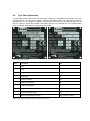
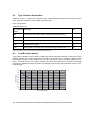
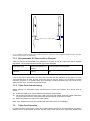
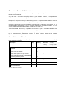
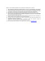
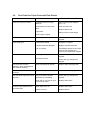
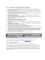
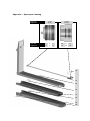
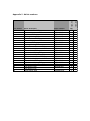
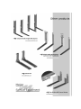
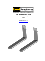
A Trademark of Meijer Special Equipment User Manual & Parts Book Order Code: RE6006 EN (3) Edition: 14-03-2012 (English) TRIPLE-FORK TRG2-30 www.telescopicforks.com Table of Contents 1 Comments ............................................................................................................ 4 2 Foreword .............................................................................................................. 5 3 Introduction ......................................................................................................... 6 4 Identification ........................................................................................................ 7 4.1 Type Information ......................................................................................................................... 7 4.2 Type Plate Explanation ............................................................................................................... 8 4.3 Type Indication Explanation ........................................................................................................ 9 4.4 Load-Bearing Capacity ............................................................................................................... 9 5 Safety.................................................................................................................. 11 6 Usage Instructions ............................................................................................ 12 7 Assembly Instructions ...................................................................................... 13 7.1 Precautions ............................................................................................................................... 13 7.2 Triple-Fork Assembly Instructions ............................................................................................ 13 7.2.1 Recommended Oil Flow and Hose Diameter ........................................................................ 14 7.2.2 Triple-Fork Commissioning ................................................................................................... 14 7.3 Triple-Fork Protection ............................................................................................................... 14 7.4 Triple-Fork Usage ..................................................................................................................... 15 8 Inspection and Maintenance ............................................................................ 16 8.1 Maintenance Schedule ............................................................................................................. 16 8.2 Fault Table for Triple-Forks with Flow Divider .......................................................................... 18 8.3 Instructions for Replacing Hydraulic Components .................................................................... 19 8.4 Ordering Components .............................................................................................................. 19 Appendices .............................................................................................................. 20 1 Comments Copyright 2012, Meijer Special Equipment VOF. All rights reserved. Unless otherwise indicated, information provided in this manual, including but not limited to the illustrations and textual content, is not to be reproduced or distributed without the prior written permission of Meijer Special Equipment. The information in this manual is provided without any form of guarantee. Under no circumstances shall Meijer Special Equipment be held liable for accidents or damage arising from the use of this manual. Please note that information in this manual may be changed at any time without prior notice. Please note that this manual may also contain technical inaccuracies and typing errors. Meijer Special Equipment makes every effort to avoid errors in this manual, but cannot guarantee this. Please inform us if you find any typing errors or technical inaccuracies, or if you have any suggestions. ® KOOI-REACHFORKS is a registered trademark of Meijer Special Equipment. Other trade or product names used in this manual, but not mentioned here, are the trademarks of their respective holders. 2 Foreword Meijer Special Equipment is the world’s largest manufacturer of hydraulic extendable and retractable ® forklift truck tines produced under the trade name KOOI-REACHFORKS . Triple-Forks were introduced in 1980 by KOOI BV, the manufacturer of the KOOI-AAP portable lift truck. However, the forks were always manufactured by Meijer BV. Since November 2000, Meijer Special Equipment (subsidiary of Meijer Holding) has been responsible for not only the production, but also for Triple-Fork sales and marketing. Congratulations on the purchase of your new Triple-Forks, a reliable product that meets the highest standards of quality and user-friendliness. You should familiarize yourself with these operating instructions before using these Triple-Forks. This manual contains everything you will need to know about these Triple-Forks and their optimal use. Our After Sales department is also at your disposal if you should require any technical assistance. ® KOOI-REACHFORKS comply with the following quality standards: 1. 2. 3. 4. 5. 6. ISO 9001:2008 – Quality Management System ISO 13284 – Fork Arm Extensions and Telescopic Fork Arms ISO 4406 – Hydraulics – Fluids – Method for Coding Levels of Solid Particle Contamination ISO 2328 – Fork-Lift Trucks – Hook-On Type Fork Arms and Fork Arm Carriages CE (2006/42/EC) – Machinery Directive ISO 3834-2 – Quality Requirements for Fusion Welding of Metallic Materials – Part 2: Comprehensive Quality Requirements Triple-Forks are randomly subjected to dynamic testing in accordance with ISO 2330 standards. 3 Introduction Triple-Forks are hydraulically retractable and extendible forklift truck tines. They are designed for a maximum service life and a minimum of maintenance. To achieve this, however, it is important that maintenance be carried out in accordance with the manufacturer’s instructions. This user manual is intended to familiarize you with these Triple-Forks. Please study it carefully before assembling and using the Triple-Forks. The manufacturer reserves the right to change specifications without prior notice. Because we constantly strive to improve the product, it is possible that the images in this manual do not correspond to the Triple-Forks that you have purchased. It is therefore important to state their type and serial number when ordering parts or requesting information. Drawings and specification sheets for all types of Triple-Fork are included in the appendices so that you can state the relevant product number when ordering. 4 Identification This section explains the information shown on the type plate. This information contains technical specifications for the Triple-Forks that are required when ordering components. It is therefore important to know what information is shown on the plate and how it should be used. 4.1 Type Information The following information should be specified when ordering components or requesting information. The serial number and type are shown on each Triple-Fork's type plate (see Fig. 4.1). This information is also engraved on the inner side of each fork. Type/Serial Number/Build Year: Type Plate Engraved Data Fig. 4.1 Type plate positioning and engraved details Manufacturer : Meijer Special Equipment Manufacturer’s Address : Oudebildtdijk 894 9079 NG Sint Jacobiparochie The Netherlands Tel. Fax Websites E-mail +31 (0)518 492929 +31 (0)518 492915 www.telescopicforks.com/www.rollerforks.com [email protected] : : : : 4.2 Type Plate Explanation The type plate can be found on the top side of each Triple-Fork. Type plates are mounted on left- and right-hand forks. The type plate contains important information about the Triple-Forks' technical specifications. Fig. 4.2 shows an example of a type plate. The letters on the left-hand plate can be found in Table 4.1, which also provides a description and units of measurement. The right-hand plate gives an example of the details a type plate might provide. Fig. 4.2 Triple-Fork type plate Letter Description A Type B Year C Serial No. (L = Left/R = Right) D Dead Mass kg E Centre of Gravity mm F Capacity (retracted) kg G Capacity (extended) kg H Load Centre (retracted) mm I Load Centre (extended) mm J Maximum Operating Pressure MPa (1 MPa = 10 bar) Table 4.1 Description of details provided on a Triple-Fork type plate Unit 4.3 Type Indication Explanation Section A in Fig. 4.1 contains the Triple-Fork type. Various details can also be derived from the type code. Table 4.2 explains the various parts of the type code. Here is an example: TRG2-30-1200-1150 Type Indication Description Section Unit TRG Fork Type (in this case a Triple-Fork with separate flow divider) 2 No. of Cylinders per Triple-Fork Set 30 Total Triple-Fork Capacity/Load Centre 600 mm × 100 kg 1200 Retracted Fork Length mm 1150 Stroke (distance between fully retracted and fully extended forks × 2) mm Table 4.2 Various parts of the type code and their associated meanings 4.4 Load-Bearing Capacity Type plates mounted on the top side of Triple-Forks include information about the Triple-Forks' loadbearing capacity. This is also engraved on the side of the Triple-Forks. It possible to determine the load-bearing capacity at each loading point for each Triple-Fork using the loading diagram shown below. Correction factors are shown vertically and load centre distances are shown horizontally measured in millimetres from the fork back. An example of how to apply this information is given on the following page. 1,1 1 0,9 correctie factor 0,8 0,7 0,6 0,5 0,4 0,3 0,2 0,1 0 600 800 1000 1200 1400 1600 1800 2000 2200 last centrum (mm) Fig. 4.3 Correction factors for the maximum load-bearing capacity for a given load centre In this example, we will be using the information as engraved on the type plate shown in Fig. 4.2, TRG2-30-1200-1150. The Triple-Forks' maximum load-bearing capacity is 30 × 100 = 3000 kg with a load centre positioned at 600 mm. It may therefore be deduced that the maximum load-bearing capacity of a single Triple-Fork is 3000/2 = 1500 kg with a load centre at 600 mm. If the Triple-Forks have been extended, then use should be made of Fig. 4.3 to calculate the corrected maximum loadbearing capacity for the load centre in question. If the load centre is at 1200 mm, then Figure 4.3 shows that a correction factor of 0.5 should be applied. The Triple-Forks' maximum capacity with a load centre at 1200 mm is thus 1500 × 0.5 = 750 kg. ! Warning: Fig. 4.3 is only applicable to the Triple-Forks themselves. The forklift truck’s residual load-bearing capacity in combination with the TripleForks should be provided by an official forklift truck dealer. 5 Safety The forklift truck driver is primarily responsible for safety. We strongly advise that your forklift truck drivers receive proper training and gain recognized certification. It is also important to observe the following safety instructions: 7. 8. 9. 10. 11. 12. 13. 14. 15. 16. Do not load the Triple-Forks beyond the limits stipulated by the manufacturer concerning lifting capacities and load centres. Retract the load whenever possible. Retract the Triple-Forks fully when moving and not carrying a load. Always drive with Triple-Forks in their lowest possible position. Never drag the Triple-Forks over the ground while driving. Never let anyone hitch a ride on Triple-Forks or the load. Defective Triple-Forks must be taken out of service until they have been repaired or replaced by a qualified technician. Before working on Triple-Forks, make sure that the forklift truck is turned off and that the hydraulic system is depressurized (take key out of ignition). Distribute the load as evenly as possible between the two Triple-Forks. Keep Triple-Fork surfaces clean and free of grease and oil. All the above points should be read and understood by the forklift truck driver. Warning: ! Never exceed the forklift truck's maximum load-bearing capacity, regardless of that stated for the Triple-Forks. Warning: ! Never walk under Triple-Forks. Warning: ! This only applies to Triple-Forks with a high pallet-stop position (Type Y2 and Y3) less than 50 mm from the fork back when retracted (measured from the front of the pallet stop to the front of the fork back). Avoid getting body parts or goods trapped or jammed between the fork back and the pallet stop when retracting the forks. This can lead to serious injury and/or damage to goods! 6 Usage Instructions Triple-Forks allow trucks to be loaded from one side, goods to be stacked double deep in warehouses, two pallets to be lifted simultaneously and pallets of varying dimensions to be lifted when using TripleForks as extendable forks. Triple-Forks are easy to assemble and dismantle. Triple-Forks mounted on forklift trucks should be properly adjusted for the purpose intended. The combined load-bearing capacity should be calculated by an accredited forklift truck dealer. The load-bearing capacity shown on the forklift truck’s type plate should be amended accordingly for the new forklift truck + Triple-Fork combination. It is strongly recommended that forklift truck drivers be properly trained in the use of these Triple-Forks. Warning: ! Contact between the Triple-Forks and the ground should be avoided as much as possible while manoeuvring to reduce wear. This prevents wear and tear to the underside of outer forks. Wear-resistant strips can also be welded to the underside of these outer forks to help prevent wear. Warning: ! Make sure that the Triple-Forks do not drag on the floor when moving in reverse. This can cause damage to the outer forks and their piston rods. 7 Assembly Instructions This section primarily deals with a number of precautions to be heeded when working with TripleForks, regardless of their type. Section 7.2 deals with the flow divider. Section 7.3 explains how to limit wear and tear to the underside of the Triple-Forks. 7.1 Precautions There are a number of precautions to be taken when assembling, inspecting and maintaining TripleForks. 17. The forklift truck should be turned off and the key removed from the ignition whenever work is being performed on Triple-Forks. 18. The forklift truck's hydraulic system should be fully depressurized whenever maintenance is being performed on the Triple-Forks. 19. Position the Triple-Forks at the most ergonomic height to prevent any back problems. 20. Wear proper work clothing, shoes and safety glasses. 21. Triple-Fork connectors should always be plugged when disconnecting the Triple-Forks from the fork carriage to prevent contamination of the hydraulic system. 22. Triple-Forks may never be welded without written permission from the manufacturer. Any TripleFork warranties shall be voided in the event that welding work is performed on Triple-Forks without this written permission. 7.2 Triple-Fork Assembly Instructions In order to get the best results from your Triple-Forks after assembly, you should follow the assembly instructions as given below: 23. An 'L' and an 'R' can be found on the Triple-Forks' type plates. Mount the Triple-Forks accordingly – left and right, as viewed from the driver’s seat in the forklift truck. 24. Slide the Triple-Forks onto the fork attachment plate, making sure that the locking pin drops into one of the recesses in the fork attachment plate. 25. Attach the hydraulic hoses supplied with the Triple-Forks and those on the forklift truck as shown in Fig. 7.1. Pay particular attention to the letters engraved on the top side of each fork. 26. Make sure that hydraulic connections have been well tightened. 27. The Triple-Forks' maximum permitted operating pressure is 250 bar. Fig. 7.1 illustrates how the hydraulic hoses should be attached for Triple-Forks with an integrated equalizer system. The figure shows the letters used on the Triple-Forks. 7.2.1 Recommended Oil Flow and Hose Diameter Table 7.1 lists the recommended hose diameters for a given oil flow for Triple-Forks with a separate flow divider. The recommended flow divider type is also indicated. Triple-Fork Type Recommended Oil Flow (L/min) Recommended Hose Diameter TRG2-30 7.5–20 3/8" Table 7.1 Recommended hose/oil flow combinations If the oil flow rate is greater than 20 L/min, then this will have little influence on the speed. It is also recommended that oil flows be kept under this level so that the pump is not required to provide maximum pressure on a constant basis thus preventing oil being pumped back to the tank via the safety release valve. This also requires less power. 7.2.2 Triple-Fork Commissioning Before starting, it is essential to make sure that there is no air in the system. This can be done as follows: 28. Incline the forklift truck mast forwards and backwards several times. 29. Tilt the mast forwards and retract the Triple-Forks using the handle. Keep the handle pulled back for 30 seconds so that the Triple-Forks stay retracted and oil continues to circulate. 30. Extend and retract the Triple-Forks several times. Next, check whether the hoses are unobstructed and that there are no oil leakages. 7.3 Triple-Fork Protection In order to prevent Triple-Forks coming into contact with the ground, we recommend that you place a plastic bush on the lift cylinder in such a way that Triple-Forks cannot touch the ground. Forklift truck lifting chains may also be shortened slightly, which has the same effect. Always consult your dealer or manufacturer before carrying out such modifications. 7.4 Triple-Fork Usage Triple-Forks are equipped with an integrated system that enables both forklift truck tines to operate in unison. If both Triple-Fork shafts are not at the same length, retract both forks entirely (rearmost position) and keep them in this position for approximately 3 seconds (while running) so that the hydraulic system has the opportunity to flush out and to bring both shafts to an equal height. In the event of a large difference between the two forks, it is advisable to keep the forks in the rearmost position for slightly longer (while running) until both forks are again at the same length. The forks are now reset. You can now continue normal operations. Both forks will now be at the same length. After each extension, it is advisable to return the Triple-Forks to the rearmost position for a few seconds using the handle. Note: ! If forks are not reset using this procedure, then they will gradually start to operate out of unison over the course of time. To resolve this problem, follow the instructions in 7.4. 8 Inspection and Maintenance Triple-Forks operate on a closed, self-lubricating hydraulic system. Triple-Forks are supplied with Rando HD 32 hydraulic oil. Very little work is required to keep Triple-Forks in good condition. However, it is important that maintenance be performed in a timely and correct fashion. Check the Triple-Forks every day for signs of damage or oil leaks. Any damage or leaks found should be reported to the person in charge. When carrying out work on Triple-Forks, the forklift truck must be switched off with the key removed from the ignition and the system depressurized. Consult the maintenance schedule for additional inspection work. Under some circumstances, e.g. in exceptionally dirty environments, it may be necessary to amend the maintenance schedule. In such cases, seals should be replaced more often, in particular, the wiper ring. Triple-Forks should be tested by a specialist at least once a year in accordance with ISO 5057 standards. The results of the test should be recorded in a logbook. If piston or cylinder head components are in need of replacement, then this work should be performed by a qualified person. Alternatively, contact an official importer listed on the website (www.telescopicforks.com). 8.1 Maintenance Schedule Table 8.1 lists which components require inspection, what actions should be taken and how frequently these should be performed. Description Daily Weekly 1 Grease the underside and topside of the inner fork X 2 Check inner fork for leaks X 3 Check wear strips for any sign of wear 4 Check for any signs of wear underneath the outer forks (especially at rear) Half-Yearly Annually or every 1,000 hours or every 2,000 hours X X 5 Check for and remove any dirt accumulated in the outer sleeve X 6 Check for any cylinder head leaks X 7 Check inner fork in accordance with ISO 5057 standards Table 8.1 Maintenance schedule X Below is a more detailed explanation of the maintenance schedule given in Table 8.1: 31. We recommend Novatex EP 2 lubricating grease, as this is a special-purpose, calcium-based grease designed to protect sliding parts from wear and corrosion when subjected to heavy loads. 32. In the event of leakage, disconnect the Triple-Forks from the forklift truck immediately and contact your supplier. In the event of connector leaks, either tighten and/or replace attachments. 33. Wear strips should be replaced or filled with packing if they wear down to less than 1.5 mm. 34. Outer forks should be replaced when the hardened wear plates on the outer fork have been worn down to such an extent that they are flush with the underside of the outer fork, or more seriously if the outer fork itself has been worn down. 35. Any dirt at the front of the sleeve can adversely affect the Triple-Forks' stroke. Depending on usage, inspection may be required more or even less frequently. 36. The wiper ring can be inspected more easily by removing the outer sleeve (see Section 8.3 for instructions on removing the outer fork). 37. International ISO 5057 standards apply to telescopic forklift tine inspection except for Section 5.6.1, as the inner fork may not be subjected to any wear. For more information about Novatex EP 2 and Rando HD 32, please visit www.texaco.com. 8.2 Fault Table for Triple-Forks with Flow Divider Symptom Possible Cause Possible Solution Forks not moving in unison Hydraulic hoses incorrectly attached Attach hoses as per diagram (Fig. 7.2) Dirt between inner and outer forks Clear out outer fork Replace piston seal Piston leak Attach hoses of equal length Hose lengths unequal Forks move on their own Operating valve leak Check with your forklift truck supplier Forks leaking oil Connections leaking Retighten or replace Cylinder head seal damaged Replace cylinder head seal Fork is cracked Immediately disconnect the forks from the fork carriage and contact your forklift truck supplier Operating valve/pump worn out Check with your forklift truck supplier Forks move unevenly Insufficient oil flow Check with your forklift truck supplier One outer fork remains stationary when retracting and then retracts suddenly Spiral clamping bush broken Replace spiral clamping bush One of the outer forks cannot be Spiral clamping bush broken retracted Replace spiral clamping bush One fork point hangs lower than the other One of the forks has been deformed by overloading Check with your forklift truck supplier Wear strip on one fork is more worn than the other Replace wear strips Wear strips worn out Replace wear strips Sleeve worn out Replace sleeve Excessive play between inner and outer forks Table 8.2 Triple-Fork fault table 8.3 Instructions for Replacing Hydraulic Components 38. Position Triple-Forks at hip height, tip the mast forwards and remove the key from the ignition. 39. Remove the outer fork by removing the Allen bolts from the side of the outer sleeve and the spiral clamping bushes from the tip. 40. Insert an M5 × 0.8 bolt into the opening on the underside of the inner sleeve and pull the lip outward and remove the bolt. Remove the inner sleeve. 41. Loosen the hose on the top side of the Triple-Fork slightly so that the piston rod does not create a vacuum when dismantling. 42. Place a drip tray below the Triple-Fork. Loosen the cylinder head using a cylinder head wrench. 43. Carefully extract the piston rod. 44. Unscrew the piston. Piston rods should be held in a fixing clamp to prevent them from being damaged. Slide the cylinder head off the piston rod. 45. Replace components. 46. Remove any Loctite from the piston rod screw thread. 47. Clean the piston rod and screw thread using Loctite 7063. 48. Slide the cylinder head back onto the piston rod. 49. When reassembling the piston on the piston rod, use Loctite 270 to prevent the piston from working loose. 50. Hold the piston rod (together with the piston and cylinder head) directly in line with the cylinder and carefully tap it in in a straight line. 51. Lubricate the cylinder head screw thread with Copaslip. 52. Carefully tighten the cylinder head using a cylinder head wrench. 53. Slide the inner sleeves back onto the fork and make sure that the lip passes the stop. Push the lip in the direction of the fork making sure that it does not hit the cylinder. 54. Reassemble the outer fork. Make sure that the piston rod clamps are positioned exactly beneath the outer fork holes. Insert a screwdriver or a bolt into one hole and hammer the new spiral clamping bush into the other hole. Remove the screwdriver or bolt from the other hole and then hammer in another spiral clamping bush. Insert the Allen bolts back into the side of the outer fork. 55. Reconnect and tighten the hose attachments. 56. Start the forklift truck up, and extend and retract the Triple-Forks several times. Item Tightening Moment (Nm) All pistons on piston rods 100 Table 8.3 Tightening moments For more information about various Loctite products, please visit the www.loctite.com website. For more information about Copaslip, please visit the www.kroon-oil.com website. 8.4 Ordering Components Any discrepancies in the Triple-Forks' bore diameter have been engraved on their side. It is recommended that you order complete assemblies whenever individual pistons, cylinder heads or even certain seals, wiper rings or guide rings need to be ordered to avoid any assembly problems. Please provide the Triple-Fork's serial number when ordering piston rods, inner and/or outer sleeves, top block stop rings (stop pins, pawls, spiral clamping bushes for pawl and ratchets) or hydraulic screw-in connectors. Appendices Appendix 1 Spare parts drawing ..................................................................................................... 21 Appendix 2 Article numbers ............................................................................................................ 22 Appendix 1 Spare parts drawing Left fork Right fork Left fork Right fork 1 (2) 5 (6) 4 8 3 7 9 (10) 14 (15) 4 8 12 17 11 16 13 18 22 27 23 24 19 25 20 26 Pos. number Article description Article number Qty 1 2 3 4 5 6 7 8 9 10 11 12 13 14 15 16 17 18 19 Piston incl. seals D30 Piston without seals D30 Piston seal D30 Piston guide ring D30 Piston incl. seals D35 Piston without seals D35 Piston seal D35 Piston guide ring D35 Cylinder head incl. seals D30 Cylinder head without seals D30 Piston rod seal D30 Cylinder head O-ring D30 Cylinder head Wiper ring D30 Cylinder head incl. seals D35 Cylinder head without seals D35 Piston rod seal D35 Cylinder head O-ring D35 Cylinder head Wiper ring D35 Inner sleeve 1200 Inner sleeve 1275 Outer sleeve 1200 RE2008042 RE0008042 RE0015002 RE0039005 RE2008043 RE0008043 RE0015003 RE0039006 RE2009031 RE0009031 RE0013016 RE0012001 RE0014011 RE2009032 RE0009032 RE0013016 RE0012003 RE0014011 BiK00041837 1 1 1 2 1 1 1 2 1 1 1 1 1 1 1 1 1 1 2 BuK00041835 2 20 1275-1225 1200-1150 Appendix 2 Article numbers 1 1 1 2 1 1 1 2 1 1 1 1 1 1 1 1 1 1 2