1
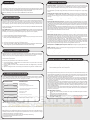
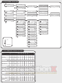
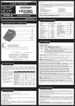
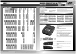
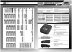
© LRP electronic GmbH 2007 LA00028 PROFESSIONAL BATTERY- & MOTOR MANAGEMENT ORDER NO.: 41552 NIMH - LIPO - NICD USER GUIDE LRP electronic GmbH Wilhelm-Enssle-Str. 132-134 73630 Remshalden Germany [email protected] www.LRP.cc Dear customer, thank you for your trust in this LRP product. By purchasing a LRP PULSAR COMPETITION 3 - Professional Battery- & Motor Management system (PCC-3), you have chosen a high-performance product. The LRP PULSAR product family has a great reputation in R/C Car sports. LRP now ties up to this great reputation with the all-new LRP PULSAR COMPETITION 3, which has the latest technology incorporated including the following High-Tech features: • LiPo charging • Multi-Step Charging • Partial Charge Mode • 4 User Profile Memories • Adjustable Voltage-Output Mode • Voltage Calibration Mode • Indication of peak voltage after charging • Advanced Digital • Limited Lifetime Warranty • Multi-Protection-System Please read the following instructions to ensure, that your LRP PULSAR COMPETITION 3 unit always works up to your full satisfaction. Please read and understand these instructions completely before you use this product! With operating this product, you accept the LRP warranty terms. 4. SPECIFICATION 1. CONNECTIONS / OPERATION The PCC-3 was developed with the main objective placed on easy operation of all features. Intuitive navigation by means of 4 buttons makes it very easy to use and the 2-line LC display offers perfect, reliable control of all settings. Input MENU DEC LED INC + Dimensions Weight Input Voltage Charging Modes 100 x 153 x 70mm 600g 11 - 15V Linear, Multi-Step & LiPo Charging Capability NiMH & NiCd Charging Capability LiPo Charge current Trickle current Delta-Peak PCS-4 Autostart Timer Discharge current 1-8 cells 1-3 cells 0.1 - 10.0A 0.0 - 0.4A 5 - 95mV yes 0 - 99min 0.1 - 10.0A Voltage Output Discharge cut-off voltage User Profile Memory Matching Mode Partial Charge Mode Advanced Digital Auto-Restart-System 3-way Multi-Protection-System Laser Blue LCD-Display Buttons Internal, programmcontrolled fan 1.0 - 12.0V / 20A 0.9 - 9.0V 4 yes yes yes yes yes yes 4 yes START/STOP Output Buttons: MENU DEC INC + START/STOP Scrolls/jumps through the function list. Decrements the underscored value.* Increments the underscored value.* Next program step / Start a program / Cancel a running program. * Button has high-speed function for rapid setting (hold down button to change value faster). Active function Charge current L i n 0 5.0 A 0 8.5 8 V Time elapsed since start 00 m 35s 0048m A h Voltage at output connectors Peak Voltage (after end of charge) Capacity The PCC-3 allows you to save 4 individual user profiles. This means you can customize 4 personal charge profiles individually and store them for later use. The PCC-3 has 4 preset works-default settings when shipped out: P1 (NiMH programm - Linear), P2 (NiMH programm - Multi-Step), P3 (2-cell LiPo programm), P4 (NiMH Receiver/Transmitter batteries programm). For details see the table below. User Profile Charge Mode Charge Current(1) Charge Current2 Charge Current3 Charge Capacity1 Charge Capacity2 Charge D-Peak Charge Trickle Charge LiPo Volt Discharge Current Discharge Voltage Volt-Out #1 Lin 5.0A ----10mV Off -10.0A 5.4V 5.0V #2 Stp 3.0A 6.0A 4.0A 0.5Ah 3.5Ah 10mV Off -10.0A 5.4V 5.0V SET Charge Mode: The PCC-3 comprises 3 charging methods: Lin 1 „Linear“ = NiMH/NiCd-charging with constant current. This is the most popular charging method for NiMH/NiCd-batteries in competition. Stp 2 „Multi-Step“ = NiMH/NiCd-charging with changeable 3-step current. This charging method allows you to charge your battery with 3 different charging currents, which are changed based on the already charged-in capacity of the battery. Lip 3 „LiPo“ = LiPo-charging using the CC/CV-charging method. With this charging method, the battery gets charged with a constant current first. As soon as the battery voltage reaches the max. charging voltage of the LiPo battery, the charger automatically reduces the charging current till the battery is fully charged. CAUTION: Only use the „LiPo“ charging method when charging a LiPo battery. „Linear“ and „Multi-Step“ charging methods may not been used to charge a LiPo battery, as this will lead to fire or explosion. Note: The following charge settings depend on the chosen charging method. The numbers in front of each charge setting indicate, if this setting is available for this particular charging method or not. 2. SETTINGS The PCC-3 indicates the current programm P1, P2, P3 or P4 by displaying it on the main menu. By pressing the INC+ and DECbuttons you can change between the profiles and their settings. To reset your PCC-3 to worksdefault settings, proceed as follows: • Disconnect input voltage. • Hold down MENU button while reconnecting the input voltage. 5. CHARGE #3 Lip 3.0A ------07.4V 10.0A 5.6V 5.0V #4 Lin 1.2A ----20mV Off -1.0A 4.0V 5.0V 1 2 3 SET Charge Current(1): The charge current can be set from 0.1 to 10.0A. If not otherwise specified by the battery manufacturer, the max. charge current should never exceed twice the nominal capacity of typical Sub-C cells used in the R/C industry. For typical LiPo batteries used in the R/C industry, the max. charge current should never exceed the nominal capacity. 2 SET Charge Curren2 (Charge current Step 2 - Multi-Step): With this setting you can adjust the charging current for Step 2 of the Multi-Step charging. This charging current gets enabled, as soon as the charged-in capacity reaches the value set with „SET Charge Capacit1“. 2 SET Charge Curren3 ((Charge Charge current Step 3 - Multi-Step): With this setting you can adjust the charging current for Step 3 of the Multi-Step charging. This charging current gets enabled, as soon as the charged-in capacity reaches the value set with „SET Charge Capacit2“. 2 SET Charge Capacit1 (Switch from Step 1 to Step 2 - Multi-Step): With this setting you set the capacity value, where the charging current changes from Step 1 to Step 2. 2 SET Charge Capacit2 (Switch from Step 2 to Step 3 - Multi-Step): With this setting you set the capacity value, where the charging current changes from Step 2 to Step 3. 1 2 SET Charge D-Peak (Delta Peak): With NiMH/NiCd-batteries, you only obtain the optimum battery performance by slightly „overcharging“ the battery. In real terms, it will not be overcharged, but charged to an optimum level. The battery voltage drops at the end of the charging process (delta). The size of the drop (delta peak) is adjustable in the range between 5 - 95mV. The higher the value, the hotter the battery will be at the end of the charge. We recommend to start with the worksdefault settings. Note: The adjustable Delta-Peak value applies to the whole battery pack and not to one single cell! 1 2 SET Charge Trickle: This current, which flows after delta peak cutoff, is adjustable from 0.0 A to 0.4 A to achieve the highest possible voltage for NiCd cells. Set this function to „Off“ for NiMH cells. 3 SET Charge LiPo Volt (LiPo max. charging voltage voltage): The max. charging voltage for LiPo batteries can be set to three different values (3.7V; 7.4V; 11.1V). Set this value in dependence of the used quantity of LiPo cells. With a 1S LiPo-pack use 3.7V, with a 2S pack use 7.4V and with a 3S pack use 11.1V. 6. DISCHARGE 3. VOLT OUT You can use this function in a number of ways. For example: • Running in brushed motors or motor brushes (check for excess current consumption). • Powering com-lathes • Powering 7.2 V soldering irons • Powering tire warmers The voltage setting, current and operating time are displayed. The output voltage can be changed on the fly during operation in 0.1V steps. SET Volt-Out: The voltage is continuously variable from 1.0 - 12.0V. The maximum current is 20A. We recommend a voltage of 4.0V for running in brushed motors. The special run-up electronics allow trouble-free running-in of motors with very high no-load currents and low number of turns when you set the PCC-3 to low voltages. The adjustable discharge circuit (0.1 to 10.0A) can be used for 1-8 cell NiMH/NiCd-packs and 1-3 cell LiPo-packs. The PCC-3 informs you about all the data relating to the battery pack, e.g. discharge time, capacity and average voltage. By discharging your battery pack on the PCC-3 after use, you obtain vital information about remaining capacity for optimizing your motor or gear ratio for the next run. This also maintains your battery packs in good condition. SET Discharge Current: The discharge current can be set from 0.1 - 10.0A. If not otherwise specified by the battery manufacturer, the max. discharge current can be set to 10.0A for typical Sub-C cells used in the R/C industry. For typical LiPo batteries with a high C-rate used in the R/C industry, the max. discharge current can be set to 10.0A aswell. However for receiver-/transmitter battery packs or LiPo batteries with a low C-rate, you should lower the discharge current according to the manufacturer‘s recommmendations. SET Discharge Voltage: The cut-off voltage can be adjusted from 0.9 - 9.0V depending on the number of cells. We recommend a cut-off voltage of 0.9V/cell with NiMH/NiCd-batteries and 2.8V/cell with LiPo-batteries. This means, for example, 5.4V for a 6-cell NiMH/NiCd-pack or 5.6V for a 2-cell LiPo-pack. 7. MATCHING 11. SPECIAL FEATURES This fully automatic matching program allows you to determine the actual performance of your packs before using them. Battery packs change during their life span. Use the PCC-3 to detect the actual quality of your packs. This prevents nasty surprises. Autostart Timer: This handy feature lets you preselect when you want to start charging your battery with the PCC-3. The Autostart Timer is adjustable from 0 - 99min. If you stay in the „Autostart Display“ for longer then 30sec without setting a value, the PCC-3 will start charging automatically. The “Matching” mode uses the charge and discharge values of the currently selected programm, stored under “Settings”. The pack is first discharged, then charged and finally discharged. At the end of the process, the pack capacity and the average discharge voltage are displayed. Auto-Restart-System: Already known from its predecessors, the PCC-3 continues to automatically charge a battery after the input voltage failed. A total power failure at races is no rarity and this feature allows you to fully charge your battery packs within the remaining time at a higher charge current. Note: The „Matching“ function can be used for NiMH/NiCd and LiPo-batteries. Changing the charge current on the fly: The charge current can be changed on the fly by pressing INC+ or DEC- without interrupting the charging process. This change is not stored. The next time you start charging, the device takes the data settings of each charge profile, stored under “Settings”. 8. PARTIAL CHARGE Never store NiMH and LiPo-batteries completeley empty. This will harm the batteries and lower their performance. Due to this fact, the PCC-3 features a „Partial charge“ mode for batteries. With this function, you can set a fixed capacity value and the PCC-3 will charge exactly this capacity amount into your battery. Thus you can always perfectly prepare your battery for storage, if you want to store them over a longer period of time. We recommend to completely discharge the battery first and then put about half of the nominal capacity back into the battery. For example, a battery with a nominal capacity of 4200mAh should be partially charged with 2100mAh. Note: NiMH batteries can be stored for about 1-2 months without problems using this method. LiPo batteries can be stored for about 6 months without problems. After this time period, you should check the battery and, if necessary, put some partial charge in again if you don´t use it regularly. To partially charge a battery, follow these instructions (see chapter 12 „Programme Structure“ for further reference): 1. Be sure, that the battery has been discharged completely. 2. Choose a suitable charging profile or adjust the charge setting in the „Settings“ menu so it fits the battery, which you want to partially charge. 3. Choose „Charge“ from the menu and press the START/STOP button to get to the Autostart setting screen. 4. Now press the MENU button once, as long as you see the Autostart setting screen. 5. The screen now changes to „Par Charge“ and 1.0Ah is preset. 6. You can now use the INC+ und DEC- buttons to adjust the amount of partial charge. After setting the partial charge value, press the START/STOP button to start the partial charge. 9. VOLTAGE CALIBRATION MODE With this function, you can calibrate the voltage shown on the menu screen. All PCC-3 units are already calibrated coming from the factory, but due to aging of the components, this calibration can slightly change over time. Then you can readjust the voltage on your PCC-3 with this function. Another advantage of this function is, that two different PCC-3 units, which have been calibrated with the „Voltage calibration mode“, will show exactly the same results. Therefore results of the „Matching“ mode can be directly compared. Indication of Peak Voltage after charging: After charging has been completed, the peak voltage (instead of the voltage at the output connectors) of the charged battery pack is shown on the display. PCS-4 (Peak Capacity System): The voltage charge curve of NiMH cells may vary considerably at the start of charging due to cell construction. Conventional chargers interpret this incorrectly as „delta peak reached“ and terminate the charging process (false peak). The PCC-3 has the updated LRP-exclusive PCS-4 which contains advanced algorithms to detect this phenomenon: This ensures reliable full charging. PCS-4 allows the perfect full charge of all NiMH cell types by means of an adjustable delta peak and high-precision digital-filter detection of all parameters throughout the entire charging process. Herewith temperature charging is obsolete! The PCC-3 signals full charge and end of charge by an alert buzzer that sounds for 3 minutes at 4-second intervals. Charging of NiMH, NiCd and LiPo-batteries: Fast Charge: 1-8 cells (NiMH/NiCd), 1-3 cells (LiPo), 0.1A to 10.0A on the fly. 3 charge modes: Linear, Multi-Step & LiPo with PCS-4 and adjustable Delta-Peak (5-95mV). Multi-Step charge mode: During Multi-Step charging, the battery will be charged with different charging currents divided into steps. The charge current and the duration of each step are adjustable. With the „Stp“ charge mode, you can divide the charge current into 3 different steps. These 3 steps will be activated in dependance of the already charged-in capacity of the battery. At the beginning of the charging process, the standard charging current is chosen (Step 1). As soon as the capacity of the battery reaches the value set with „SET Charge Capacit1“ (see chapter 5 „Charge“ for further reference), the charge current switches to Step 2. As soon as the capacity of the battery reaches the value set with „SET Charge Capacit2“, the charge current switches to Step 3 and the the battery will be charged with this charge current till reaching the Delta-Peak cut-off. Discharging of NiMH, NiCd and LiPo-batteries: Variable 0.1 to 10.0A discharge current adjustable on the fly. Displays discharge time, capacity and average voltage. Adjustable cut-off voltage from 0.9 to 9.0V. PWM - Circuit: The PCC-3 ensures efficient charging through the use of the latest digital technology. There are many benefits here: 1. Maximum charge current even at low input voltage. 2. Maxium charge current already for 1-cell (for NiMH/NiCd aswell as for LiPo-batteries). 3. Very low heating of the charger itself. 4. More charges out of a single car battery since the charger has a higher efficiency. REPAIR PROCEDURES / LIMITED WARRANTY To enter the „Voltage calibration mode“, follow these instructions: 1. Press and hold the INC+ and DEC- buttons and connect the PCC-3 to a power source. The charger is now in voltage calibration mode. 2. Connect a battery to the PCC-3. Take a voltmeter and measure the voltage directly at the battery connectors. 3. Adjust the voltage on the PCC-3 to the voltage on the voltmeter using the INC+ and DEC- buttons. 4. To save the new value and to return back to the main menu, press the START/STOP button once. 10. TROUBLESHOOTING GUIDE The PCC-3 is protected against faults and operator errors by the Multi-Protection-System. Faults/Errors are displayed on the LCD screen and some faults/errors may interrupt the charging process to protect the charger and the battery. The error messages are as follows: ERROR-MESSAGES C AU TION BAT ERR POSSIBLE CAUSES - Wrong battery polarity, bad contact? - Defective battery? - Wrong LiPo-cell quantity? INTERRUPT I/P HI - Input voltage too high (higher than 15.8V) INTERRUPT I/P L O W - Input voltage too low/switched off (lower than 10.0V) - Bad contact on input clamps? C AU TION AMP HI - Motor current >20A? - Motor defective? C AU TION TEMP HI - Temperature of the charger too high. C AU TION VOLT HI - Cell quantity during discharge too high? LCD: LCD stays dark, no function -> Change the fuse Fan: Fan is program-controlled and only runs when necessary. It is no fault if fan doesn‘t run continuously. Input Low: If input voltage is too low, the PCC-3 will continue to charge and automatically sets the charge current to a lower value to make sure that the battery gets fully charged. If this function is active, “Inp Low” appears in the LCD alternating with the input voltage reading. You cannot increase the charge current manually. Fuse: The PCC-3 has an additional internal fuse which protects the charger from irreparable damage if operated incorrectly! The PCC-3 is supplied with a replacement fuse. It is easy to replace. To change the fuse, proceed as follows: 1. Make sure that nothing is connected to the PCC-3. 2. Unscrew the two screws at the bottom of the case and fold open the housing. 3. Remove the defective fuse and insert a new fuse. 4. Close the PCC-3 again. All products from LRP electronic GmbH (hereinafter called “LRP”) are manufactured according to the highest quality standards. LRP guarantees this product to be free from defects in materials or workmanship for 90 days (non-european countris only) from the original date of purchase verified by sales receipt. This limited warranty doesn’t cover defects, which are a result of normal wear, misuse or improper maintenance. This applies among other things on: • Cut off/changed original input- and/or output-wires • Mechanical damage of the case • Humidity/Water inside the case • Mechanical damage of electronical components/PCB • Soldered on the PCB With Limited Lifetime Warranty products, the warranty terms on the Limited Lifetime Warranty card do also apply. To eliminate all other possibilities or improper handling, first check all other components and the trouble shooting guide, if available, before you send in this product for repair or warranty. Products sent in for repair, that operate perfect have to be charged with a service fee. By sending in this product, you assign LRP to repair the product, if it is no warranty or Limited Lifetime Warranty case. The original sales receipt including date of purchase needs to be included. Otherwise, no warranty can be granted. For quick repair- and return service, add your address and detailed description of the malfunction. Because we don’t have control over the installation or use of this product, we can‘t accept any liability for any damages resulting from using this product. Therefore using this product is at owner‘s risk. Our limited warranty liability shall be limited to repairing the unit to our original specifications. In no case shall our liability exceed the original cost of the unit. By installing or operating this product, the user accepts all resulting liability. The specifications like weight, size and others should be seen as guide values. Due to ongoing technical improvements, which are done in the interest of the product, LRP does not take any responsibility for the accuracy of these specs. LRP-Distributor-Service: • Package your product carefully and include sales receipt and detailed description of malfunction. • Send parcel to your national LRP distributor. • Distributor repairs or exchanges the product. • Shipment back to you usually by COD (cash on delivery), but this is subject to your national LRP distributor‘s general policy. 12. PROGRAMME STRUCTURE P1 MENU Charge START MENU Charge A uto sta r t: 00 m i n MENU START D-P e a k: Trickle: START Par Charge C a p a c i t y: 1.0 A h 10mV Off L i n 0 5.0 A 0 8.58 V 00m 35s 0048m A h I n p 1 3 .7 V 0 8.59 V 00 m 37s 0051m A h Done 0 9.0 6 V 50m03s 4170 m A h MENU P1 MENU Discharge START MENU Match START M at-Dis c h 0012s 0 6.51V 0033m A h MENU Volt-O ut START Volt-O ut 0 5.0 V MENU Settings START Voltage: D o n e A v g : 0 7. 3 9 6 V 0 7.7 4 V 3950 m A h D i s c h 10.0 A 0 0 29 s 0 7. 6 1 V 0080m A h 5.4V Done 0 7.7 5 V MENU P1 MENU P1 M a t 0 5.0 A 0 8.60 V 00m40s 0055m A h I n p 1 3 .7 V 0 8.60 V 00m42s 0058m A h 1422s 3950 m A h M at-Dis c h 0120s 0 7. 5 8 V 0333m A h 0030s 0 8.31 A MENU P1 MENU SET Charge Mode: Lin SET Charge Mode: Stp DEC INC MENU MENU SET Charge C u r r e n t: 0 5.0 A SET Charge C u r r e n 1: 03.0 A SET Charge C u r r e n t: 03.0 A MENU MENU MENU SET Charge C u r r e n 2: 0 6.0 A MENU MENU SET Charge Trickle: Off SET Charge C u r r e n 3: 0 4.0 A SET Discharge C u r r e n t: 10.0 A MENU MENU MENU SET Charge C a p a c it 1: 0.5 A h MENU MENU SET Discharge V o lt a g e : 5.4V MENU MENU MENU SET Charge Trickle: Off EXPLANATION OF ICONS MENU MENU press START press MENU press SET Discharge V o lt a g e : 5.4V SET Discharge C u r r e n t: 10.0 A MENU automatically SE T Volt-O ut V o l t a g e : 5.0 V MENU 13. RECOMMENDED CHARGE SETTINGS Voltage Cells Type MODE Charge Current(1) Charge Curren2 Charge Curren3 Charge Charge D-Peak Trickle Capacit1 Capacit2 LiPo Volt Budget Stickpacks Wild Pack 1600 / 1800 7100x 7.2V 6 NiCd Lin 3.5A -- -- -- -- 50mV 0.1A -- Sport Pack 2200 71011 7.2V 6 NiCd Lin 4.5A -- -- -- -- 50mV 0.1A -- Power Pack 3000 71301 7.2V 6 NiMH Lin 5.0A -- -- -- -- 10mV OFF -- Hyper Pack 4000 76400 7.2V 6 NiMH Stp 3.0A 6.0A 4.0A 0.5Ah 3.5Ah 10mV OFF -- VTEC SC-3700UP / SC-3800UP 768xx 7.2V 6 NiMH Lin 5.0A -- -- -- -- 15mV OFF -- VTEC SC-4200UP (Linear) 770xx 7.2V 4 NiMH Lin 5.5A -- -- -- -- 5mV OFF -- VTEC SC-4200UP (Linear) 770xx 7.2V 5 NiMH Lin 5.5A -- -- -- -- 10mV OFF -- VTEC SC-4200UP (Linear) 770xx 7.2V 6 NiMH Lin 5.5A -- -- -- -- 10mV OFF -- VTEC SC-4200UP (Multi-Step) 770xx 7.2V 6 NiMH Stp 3.0A 6.0A 4.0A 0.5Ah 3.5Ah 10mV OFF -- 78220 9.6V 8 NiMH Lin 1.2A -- -- -- -- 20mV OFF -- 6585x 6.0V 5 NiMH Lin 1.5A -- -- -- -- 10mV OFF -- VTEC 1400EP 752xx 7.2V 6 NiMH Lin 2.0A -- -- -- -- 20mV OFF -- VTEC 1400EP 75235 8.4V 7 NiMH Lin 2.0A -- -- -- -- 25mV OFF -- LiPo Packs Flug 480mAh Flug 3300mAh Car Micro 1/18 1800mAh Car SubC 1/10 5000mAh TX Only Packs RX Only Packs 79020 11.1V 79320 11.1V 79820 7.4V 79860 7.4V 799xx 11.1V 799xx 7.4v 3S 3S 2S 2S 3S 2S LiPo LiPo LiPo LiPo LiPo LiPo Lip Lip Lip Lip Lip Lip 0.5A 3.3A 1.8A 5.0A 1.5A 1.5A ------- ------- ------- ------- ------- ------- 11.1V 11.1V 7.4V 7.4V 11.1V 7.4V Sub-C Competition Cells VTEC AA/Mignon Cells VTEC AA-2700UC RX Packs VTEC 1400UC SE T Volt-O ut V o l t a g e : 5.0 V MENU SET Charge D-P e a k: 10 mV MENU SET Discharge V o lt a g e : 5.6 V MENU SET Charge C a p a c i t 2: 3.5 A h SE T Volt-O ut V o l t a g e : 5.0 V Order No. SET Charge L i P o V o l t : 0 7. 4 V MENU SET Discharge C u r r e n t: 10.0 A Battery Type SET Charge Mode: Lip MENU SET Charge D-P e a k: 10 mV DEC INC DEC INC Micro Packs D o n e A v g : 0 7. 3 8 3 V 0 7.7 2 V 4023m A h Done 0 7.7 2 V 1448s 4023m A h