1
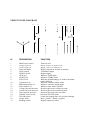
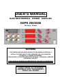
USER’S MANUAL
ELECTROPHORESIS POWER SUPPLIES
GEPS 200/2000
200 Volts - 2Amps
WARNING
THE POWER SUPPLIES ARE CAPABLE OF DELIVERING POTENTIALLY
LETHAL VOLTAGE AND IS TO BE OPERATED ONLY BY QUALIFIED
TECHNICALLY TRAINED PERSONNEL.
PLEASE READ THE ENTIRE OPERATOR'S MANUAL THOROUGHLY BEFORE
OPERATING THIS UNIT.
TAKE CARE AS THE MODE OF OPERATION OF THIS UNIT IS CONTINUOUS
PLEASE RETAIN ALL PACKAGING
MATERIALS UNTIL THE WARRANTY
PERIOD HAS EXPIRED
Description
Microprocessor controlled switching Power Supplies
.
These power supplies are CE marked and complies with the following
requirements : EMC directive 89/336/CEE. It is also certified and
manufactured according to the IEC 1010-1 standard and test regulation.
.
They are equipped with an automatic restart system in case of mains
failure.
When the power returns, an audible alarm sounds for 10 seconds and the
power automatically restarts with the previous set values.
If during the power failure the electrophoresis unit is disconnected from the
power supply, the alarm still sounds when the mains supply returns.
Because no load is connected the power supply will immediately shutdown and set the output to zero.
.
Direct reading of programmed set values and actual values before and
during the cycle.
.
.
.
Volt, mA and Timer adjustable during a cycle.
Timer for automatic shutdown of output.
Stabilisation and automatic crossover between the parameters
according to the set limitation values and when output limits are reached. 2
Red LED indicate the constant mode.
.
.
.
2 operating modes : constant voltage - constant current.
Settings by tactile switches on moisture resistant membrane panel
Battery-backed memory feature "save" last output set values in the
event of a power failure or when the run is terminated and the unit is
turned off.
.
.
3 Red LED Displays for set and output Volt, Current and time values.
3 recessed safety output jacks allow simultaneous operation of 3
electrophoresis units.
.
Fault detection and 500µA current leakage detection or no load
automatically shuts down output and indicates the fault by yellow LED
blinking.
Safety precautions
THE POWER SUPPLIES ARE CAPABLE OF DELIVERING POTENTIALLY
LETHAL VOLTAGE AND IS TO BE OPERATED ONLY BY QUALIFIED
TECHNICALLY TRAINED PERSONNEL. PLEASE READ THE ENTIRE
OPERATOR'S MANUAL THOROUGHLY BEFORE OPERATING THIS UNIT.
TAKE CARE AS THE MODE OF OPERATION OF THE UNIT IS CONTINUOUS
If the power supply is used in a manner not specified by ELCHROM, then
the protection systems of the equipment may be impaired.
For additional information, please call the ELCHROM or your distributor
Technical Resources Department.
Never attempt to remove the outer casing or make any repairs to the unit.
Contact us immediately if the need for repair or servicing should arise.
The unit must be earthed. Use only the line cord supplied
with the unit for safe operation
Check the mains plug of the line cord to make sure it is equipped with a
protection fuse not exceeding 3 A. The use of a line cord other than this or
one supplied by ELCHROM may result in user hazard.
Connect the line cord directly into a properly rated, 210/250 VAC 50/60 Hz
or 105/125VAC 50/60Hz three pins wall outlet.
For connection between the power supply and the
electrophoresis equipment, use only the safety output
power cords equipped with Black and Red recessed plugs
as supplied with the unit.
Check the power cords and the black and red recessed safety jacks
periodically to make sure that they are in good condition. Do not use cords
which are cracked, nicked or in otherwise poor condition.
Always make all connections between the power supply and the
electrophoresis equipment prior to start-up of the output.
Never place any objects other than high voltage connectors rated to
1000V into the output jacks.
Site the unit such that the rear panel has at least 20 cm of clearance to
provide for adequate unit ventilation.
The power supply must only be connected to
electrophoresis equipment manufactured with built-in
safety protected male plugs.
It is also recommended to use electrophoresis equipment
that can only be connected when the protection lids are
closed.
Specifications
Mains supply voltage fluctuations not to exceed ± 10% of the normal voltage
Mains supply, 110V model :
Mains supply, 220V model :
Fuse value in the mains plug (UK):
Rated input power/current
GEPS 200/2000
V - I range
Power
Timer range
Mode of operation
Switching frequency
Output regulation stability
Minimum output
Value display accuracy
Mains failure during the run :
Fault detection
Fault status
Earth leakage detection level
Output to earth impedance
Size
Weight
Environmental conditions
90 - 130V; 50 - 60Hz; T4A fuses
180 - 260V; 50 - 60Hz; T2A fuses
3A
400 VA
1 - 200 Volts ; 1Volt step
1 - 1998 mA; 2mA step
0,6 –300 watts
1 - 9999 minutes; 1minute step
Continuous
23 kHz
± 0,2% FS ± ½ digit
5 Volts; 15µA; 0,6 Watts
± 0,2 FS ± ½ digit
Buzzer, then automatic restart with
previous set values
Output supply stop, buzzer
Yellow LED blinking
Output to earth leakage
Output open circuit
Output short circuit
No regulation (Overheating, power circuit fault)
500µA
10Mõ min bypassed by 1nF max
34 cm x 27 cm x 11 cm ( D x W x H )
4 kg
Indoor use,
Altitude up to 2000m
Temperature 10°C - 40°C
Maximum relative RH 80% for temperature up to 31°C decreasing linearly to 50%
RH at 40°C.
CLEANING
The power supply may be cleaned as required when the main
supply is isolated.
Cleaning should be carried out with a cloth moistened with
water or with tissues impregnated with 70% Iso-propyl alcohol.
No other cleaning solutions should be used.
MAINTENANCE
There are no internal operator serviceable parts in this Power
supply.
If the power should fail, the unit must be returned to the
authorised Service centre.
See troubleshooting guide.
SHIPMENT
When shipment or transport of the power supply is required,
use the packaging supplied with the unit.
Store the unit in the packaging and in a dry area.
OPERATION
The power supply automatically RESTART when the power is operating again
after a power failure or repetitive micro failures during a cycle.
In this situation, the elapsed time until the failure is saved and memorised.
When the mains is operating again after the failure, an audible alarm rings and
the STOP LED blinks for 10 seconds.
Then the power supply RESTART automatically with respect to the set values.
Unit power up
1. Connect the AC line cord to a grounded, 3-prong wall outlet.
2. Connect the power supply to an electrophoresis device using the power cords
supplied.
3. Press the main POWER switch to turn the power supply on. The STOP LED (red)
will illuminate, and the output Leds will display zeros.
Adjusting Output Set Values
When the main power switch is turned on, default output values are displayed. To
change the output settings, use the Volt, mA or minutes dedicated tactile switches to
increase or decrease the voltage, current or time settings.
As soon as one of these switches is activated, the output Leds will display output set
values rather than actual output values. When they are released, the output LED will
display output set values for 3 seconds, and then will display actual output ( All zeros
since output has not yet be started )
Maximum output values are as follow :
GEPS 200/2000
for 200 Volts - maximum current 1500 mA ( 300 Watts )
for 1998 mA - maximum voltage 150 Volts ( 300 Watts )
FRONT PANEL DIAGRAM
18
N°
11
10
2
12
3
4
DESCRIPTION
13
14
15
5
6
16 17
8
7
9 19
FONCTION
1
Main Power switch
Turns on unit
2
3
Voltage output Led
Current output Led
Display actual or set output in Volts
Display actual or set output in mA
4
5
6
7
8
9
Time in minutes
STOP switch
START switch
STOP led
START led
FAULT led
10
11
12
13
14
15
16
17
18
19
Volt mode Led
Milliamps mode Led
Timer mode Led
Voltage increase/decrease
Current increase/decrease
Time increase/decrease
ON/OFF timer switch
CLEAR switch
Output Jacks
Reading switch
Display elapsed or set time in minutes
Terminates output
Begins output
Indicates STOP mode
Indicates START mode
Indicates ground leakage, no load or automatic
restart situation
Indicates constant voltage mode
Indicates constant current mode
Indicates timer mode ON/OFF
Increases/decreases voltage set point
Increases/decreases current set point
Increases/decreases time set mode
Put timer ON/OFF mode
Cancel the elapsed time of a previous running
Red = positive ; Black = negative
Display output set values
1
Initiating Output without timer mode
1. If the green LED located on the left of the TIMER is alighted , depress the
ON/OFF switch of the TIMER on OFF position : the green LED located on the left of
the display must be off.
2. Depress the START switch to initiate output. The START LED (green) will
illuminate, and the output Leds will display the actual values simultaneously.
Depending on the output set values one of the two modes Leds ( VOLTS,
MILLIAMPS ) will illuminate, indicating the parameter controlling output.
Slight increases or decreases in output readings for those parameters not "limiting"
will occur as the experiment progresses. These changes accurately represent
changes in the resistive load ( electrophoresis unit ) due to changes in temperature,
buffer capacity, etc. This is to be expected.
3. To view the output set values during the run, depress the READING switch. The
Leds will display the output set values as long as READING switch is depressed.
Once the READING switch is released, the Leds will display the output set values for
three seconds, and then switch back to displaying the actual output values.
4. It is possible to change the values during the run without depressing the STOP
switch.
To change the output set values during the run, depress the increase or decrease
tactile switch until the appropriate output set value is reached.
In START status, when the reading switch is depressed, the Leds will display the
output set values during three seconds and then switch back to displaying the actual
output values.
5. To establish the limiting (constant) mode for the particular experiment, set the
controlling parameter to the output desired, and increase the other output set value
until the appropriate MODE LED (VOLT, MILLIAMPs ) illuminates.
If the non-controlling output set values is reached during the course of the run, the
power supply will automatically crossover to the new mode and control output relative
to that mode. The appropriate MODE led will illuminate.
If automatic crossover is desired during the run, adjust the output set value of the
second controlling parameter to the maximum setting desired. When actual output
relative to the second controlling parameter equals its output set value, the output will
cross over from the first controlling parameter to the second.
6. When the run has been completed, depress the STOP switch to cease power
output. Wait one minute before disconnecting the power cords from the gel unit. Turn
the main power switch off when the unit is not in use.
Initiating Output with timer mode
1. If the green LED located on the left of the TIMER is not alighted , depress the
ON/OFF switch to activate the TIMER : then the green Led located on the left of the
display illuminates.
2. Depress the CLEAR switch to cancel the previous elapsed values.
3. Set the new value in minutes by depressing the increasing and decreasing
switches.
To change the output settings, use the V - mA dedicated tactile switches to increase
or decrease the voltage or current settings.
4. Depress the START switch to initiate output. The START LED (green) will
illuminate, and the output Leds will display the actual values simultaneously.
Depending on the output set values one of the two modes Leds ( VOLTS,
MILLIAMPS ) will illuminate, indicating the parameter controlling output.
Slight increases or decreases in output readings for those parameters not "limiting"
will occur as the experiment progresses. These changes accurately represent
changes in the resistive load ( electrophoresis unit ) due to changes in temperature,
buffer capacity, etc. This is to be expected.
5. To view the output set values during the run, depress the READING switch. The
leds will display the output set values as long as READING switch is depressed.
Once the READING switch is released, the Leds will display the output set values for
three seconds, and then switch back to displaying the actual output values.
6. It is possible to change the set values during the run without depressing the STOP
switch.
To change the output set values during the run, depress the increase or decrease
tactile switch until the appropriate output set value is reached.
In START status, when the set switch is moved, the leds will display the output set
values during three seconds and then switch back to displaying the actual output
values.
7. To establish the limiting (constant) mode for the particular experiment, set the
controlling parameter to the output desired, and increase the other output set value
until the appropriate MODE LED (VOLT, MILLIAMPs ) illuminates.
If the non-controlling output set values is reached during the course of the run, the
power supply will automatically crossover to the new mode and control output relative
to that mode. The appropriate MODE LED will illuminate.
If automatic crossover is desired during the run, adjust the output set value of the
second controlling parameter to the maximum setting desired. When actual output
relative to the second controlling parameter equals its output set value, the output will
cross over from the first controlling parameter to the second.
8. When the set time is elapsed, the output is automatically shutdown.
Volt and mA display zero and timer shows the set time.
Wait one minute before disconnecting the power cords from the gel unit.
Turn the main power switch off when the unit is not in use.
User's protection and safety
A Yellow LED indicates a fault situation and cut off the power supply :
1/ Overload.
2/ Output to earth leakage
3/ Output open circuit
4/ Chamber lead (s) disconnected or defective.
5/ Output short circuit.
Press STOP to resume and look for the wrong situation.
Press START to run again.
TROUBLESHOOTING GUIDE
CONDITION
PROBABLE CAUSE
REMEDY
Display fails to illuminate
when the POWER switch
is put on.
Fuses have blown
See Warning below
The desired MODE is not
flashing.
One of the other
parameters is
limiting output.
Increase the output set
value of the parameter
controlling output until
the desired output
mode is controlling.
Two different modes are
blinking alternatively.
Settings for both
parameters are too
close to the actual
output.
Increase the set value
for the mode you do not
wish to be limiting.
The time does not elapse
TIMER mode is OFF
Put the TIMER ON by
depressing the ON/OFF
switch located under
the timer display
The TIMER mode is ON but after
a mains failure the set values
are not saved and other set
values are displayed
The new set values
were not memorised.
Set again the new
values and depress the
START switch to
memorise the new values.
TIMER mode is ON, all other
parameters are correctly set but
the unit returns on FAULT/STOP
mode when pressing the START
switch
1 - Settings are wrong
2 - Fault situation
1 -Check the settings V/ mA
2 - Check the connections
on the electrophoresis
chamber
3 - Depress the CLEAR switch
3 - Timer is not cleared
WARNING
Never attempt to remove the outer casing or make any unit repairs.
Contact ELCHROM if the need for repair or servicing should arise
Should the power supply fail, DO NOT remove the outer case of the unit
and attempt any repairs.
Contact ELCHROM if the need for servicing the unit should arise
WARRANTY
ELCHROM warrants apparatus of its manufacture against defects in materials and workmanship,
under normal service ; for three years from the date of receipt by the purchaser. This warranty
excluded damages resulting from shipping, misuse, carelessness, or neglect.
ELCHROM liability under the warranty is limited to the repair of such defects or the replacement of
the
product, at its option, and is subject to receipt of reasonable proof by the customer that the defect is is
embraced within the terms of the warranty. All claims mate under this warranty must be presented to
ELCHROM within 3 years following the date of delivery of the product to the customer.
This warranty is in lieu of any other warranties or guarantees, expressed or implied, arising by law or
otherwise. ELCHROM makes no other warranty, expressed or implied, including warranties of
merchantability of fitness for a particular purpose. Under no circumstances shall.
ELCHROM be liable for damages either consequential, compensatory, incidental or special, sounding
in
negligence, strict liability, breach of warranty or any other theory, arising out of the use of the product
listed herein.
ELCHROM reserves the right to make improvements in design, construction, and appearance without
notice.
Declaration of conformity and CE mark
The information outlined in this section applies only to customers located in the European Union (EU).
This laboratory apparatus is identified with the CE mark. This mark indicates that the product
complies
to the following EU Directives and Standards :
72/23/EEC
89/336/EEC
Low voltage directive
Electromagnetic Compatibility
EN 61010-1 : 1993
EN 50081-1 : 1992
EN 50082-1 : 1992
Product safety
Emissions
Immunity
A copy of the declaration of conformity certificate is available upon request.
13