1
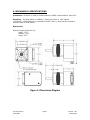
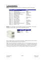
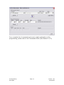
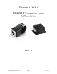
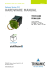
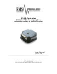
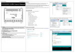
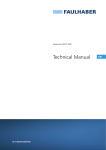
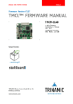
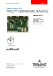
SilverPakT Integrated
Controller/Driver and Motor
User Manual - 1 of 2
Reference Guide
Version 1.04
Lin Engineering
1990 Russell Ave
Santa Clara, CA 95054
www.linengineering.com
[email protected]
Thank you for purchasing the SilverPakT module. This product is warranted to be
free of manufacturing defects for one year from the date of purchase.
PLEASE READ BEFORE USING
Before you start, you must have a suitable DC power supply suitable for the motor.
The power supply voltage must be between 4 times and 20 times the motor’s rated
voltage.
DISCLAIMER
The information provided in this document is believed to be reliable. However, no
responsibility is assumed for any possible inaccuracies or omissions. Specifications
are subject to change without notice.
Lin Engineering reserves the right to make changes without further notice to any
products herein to improve reliability, function, or design. Lin Engineering does not
assume any liability arising out of the application or use of any product or circuit
described herein; neither does it convey any license under its patent rights, nor the
rights of others.
Lin Engineering
SilverpakT
Page 2
Version 1.04
10/06/2006
Table of Contents
1. INTRODUCTION ................................................................... 4
2. FEATURES ............................................................................ 5
Figure 2.1: R364 Simplified Block Diagram.................................................. 5
3. ELECTRICAL SPECIFICATIONS.............................................. 6
I/O Specifications ................................................................................ 6
4. OPERATING SPECIFICATIONS .............................................. 6
Operating Temperature ........................................................................ 6
5. COMMUNICATION SPECIFICATIONS ..................................... 6
6. MECHANICAL SPECIFICATIONS ............................................ 7
Figure 2: Dimensions Diagram .................................................................. 7
7. PIN ASSIGNMENTS............................................................... 8
Main Power .......................................................................................... 8
RS485 .................................................................................................. 8
Additional I/O ...................................................................................... 8
9. CONNECTION SPECIFICATIONS............................................ 9
List of Parts:.......................................................................... 9
Figure 3: Connection Diagram ................................................................... 9
5. RUNNING THE SILVERPAKT................................................ 11
Lin Engineering
SilverpakT
Page 3
Version 1.04
10/06/2006
1. INTRODUCTION
The SilverpakT is an integrated TMCM110 unit with a two-phase bipolar stepper
motor. The SilverpakT has two limit switches (left and right), one additional general
purpose input (analog or digital) and one general purpose output (up to 100mA). It
communicates via RS485. To communicate via USB or RS232 a USB485 or
RS232485 converter card may be purchased through Lin Engineering.
The module is also equipped with a 5V voltage regulator and thus needs only one
power supply: the motor power supply of 7..28V DC.
The module can be programmed using the Trinamic Motion Control Language (TMCL)
which allows to control the module by a host or to run stand alone, executing a TMCL
program that is stored in the 16kByte EEPROM on the module (the EEPROM can store
up to 2000 TMCL commands).
The SilverpakT contains the TMCM-110-42/SG chip, which is equipped with a
TMC246 stepper motor driver so that StallGuard is also possible. StallGuard detects
a stall in the motor without the use of an encoder. Stall thresholds may be
programmed.
Lin Engineering
SilverpakT
Page 4
Version 1.04
10/06/2006
2. FEATURES
•
•
•
•
•
•
•
•
•
•
•
•
Input voltage of 7 to 28VDC
Output current of 0 to 1.5 Amps Peak
Step resolution of full step, half step, 4x, 8x, 16x microstep
Communication via RS485
Two limit switches (digital) available
One general purpose input (digital or analog)
One open collector output (up to 100 mA, freewheeling diode included)
Microcontroller: ATmega32, 16MHz clock frequency
Motion controller: TMC428
Step Motor Driver: TMC246
TMCL Program Memory of 16kByte EEPROM (2048 TMCL commands)
StallGuard Available
TMC
246
Figure 1: SilverpakT Simplified Block Diagram
StallGuard
The TMCM-110-42/SG module is equipped with the StallGuard feature. The StallGuard feature
makes it possible to detect if the mechanical load on a stepper motor is too high or if the traveler
has been obstructed. The load value can be read using a TMCL command or the module can be
programmed so that the motor will be stopped automatically when it has been obstructed or the
load has been to high.
Lin Engineering
SilverpakT
Page 5
Version 1.04
10/06/2006
StallGuard can also be used for finding the reference position without the need for a reference
switch: Just activate StallGuard and then let the traveler run against a mechanical obstacle that is
placed at the end of the way. When the motor has stopped it is definitely at the end of its way,
and this point can be used as the reference position.
Please see the SilverpakT Commands Guide Manual on how to activate the StallGuard feature.
3. ELECTRICAL SPECIFICATIONS
Supply Voltage:
Peak Current:
7 to 28 VDC
0 to 1.5 Amps (Software Programmable)
I/O Specifications
Inputs:
Outputs:
2 limit switches (Digital)
1 general purpose (Digital TTL or Analog 0-5v)
1 open collector output
4. OPERATING SPECIFICATIONS
Maximum Step Frequency
Operating Temperature
Up to 500kHz Microsteps (30kHz Full Step)
0° to 50° Celsius (ambient)
5. COMMUNICATION SPECIFICATIONS
Interface Type
Baud Rate
# Bits per character
Parity
Stop Bit
Flow Control
Lin Engineering
SilverpakT
RS485
Standard rates in the range 9600 to 57600 bits per
second (bps)
8 data bits
None
2
None
Page 6
Version 1.04
10/06/2006
6. MECHANICAL SPECIFICATIONS
Connectors –A DB15F is used for Power and Gnd, RS485 communication, and I/O’s.
Mounting – The Step Motor is a NEMA 17 frame size which is 1.66” square
(42.16mm). Shaft diameter is a standard 0.1968” (5mm), which can be coupled to
another shaft or other device.
Dimensions
Overall Length (dimension D):
Small: 2.72”
Medium: 2.92”
Large: 3.27”
Figure 2: Dimensions Diagram
Lin Engineering
SilverpakT
Page 7
Version 1.04
10/06/2006
7. PIN ASSIGNMENTS
DB15 – The DB15 connector (female) is provided along with the SilverpakT.
CON J5
1
2
3
4
5
6
7
8
9
10
11
12
13
14
15
Function
Power Ground (GND)
RS485 Ground
+5V DC Output (max. 20mA)
Right Limit input
General Purpose Output
VDD(Same as
No Connection
RS485+ (RxD)
+7 to 28VDC
No Connection
Left Limit Input
Signal Ground
Signal Ground
General Purpose Input(A/D)
RS485- (TxD)
Color
Green
Black
White/Green
Yellow
Orange
Yellow/White
-Black/White
Red
-Blue/White
Green/White
White
Red/White
Dark Brown
RS485 – The SilverpakT uses an RS485 interface to communicate. If using the
USB485 converter card, here are the corresponding pinouts:
RS485+
GND
RS485-
USB485
Pin 1
Pin 2
Pin 3
SilverpakT
Pin 8
Pin 2
Pin 15
Note: Another option is to purchase an RS232 to RS485 converter card in order to
use your PC’s serial COM port for communications.
I/O – The Left and Right Limit Switches (Pins 1 and 2) are digital inputs that will
read a 5VDC signal as high and 0VDC signal as low. The General Purpose Output
(Pin 4) is an open collector output that can withstand a maximum of 100 mAmps.
The General Purpose Input (Pin 7) can be used as a digital or an analog input.
Lin Engineering
SilverpakT
Page 8
Version 1.04
10/06/2006
8. CONNECTION SPECIFICATIONS
List of Parts:
•
•
•
•
•
SilverPakT unit
DB15 Cable
USB485 converter card (optional) or RS485-RS232 Converter Card(optional)
Power supply +7 to 28VDC
PC
Follow the schematic for correct connection:
Figure 3: USB485 Connection Diagram
Figure 4. RS485 to RS232 Connection Diagram
Lin Engineering
SilverpakT
Page 9
Version 1.04
10/06/2006
9. PROGRAMMING THE SILVERPAK T
1. Download the TMCL Program. Example programs are included. One of the
sample programs is labeled as ‘Motor Config.tmc’. Open this program using the
TMCL program
2. ‘Motor Config.tmc’ will show basic setup for microstepping, StallGuard Threshold,
velocities, output current, acceleration, and decay modes. This program will rotate
right for 1000 steps. Please be sure the motor shaft is not attached to a device that
may cause harm.
3. To setup the correct COM port, go
to Setup Æ Options Æ Connection.
Select the correct COM port.
To ensure you have the right COM
port, right click on My Computer. Go
to Properties. Then click on the
Hardware tab. Click on Device
Manager. You should see a list of
COM settings. Please verify with the
list.
4. To compile and run the program, you must first Assemble the program:
Then download the program:
Lin Engineering
SilverpakT
Page 10
Version 1.04
10/06/2006
Finally, click on the Run button:
5. To run the SilverpakT in Direct Mode, go to TMCL Æ Direct Mode. Commands can
be executed on the fly to for testing purposes.
Lin Engineering
SilverpakT
Page 11
Version 1.04
10/06/2006
For a complete list of commands and more in depth explanation of the
programming, please refer to the Commands Guide (User Manual 2 of 2).
Lin Engineering
SilverpakT
Page 12
Version 1.04
10/06/2006