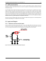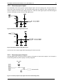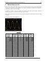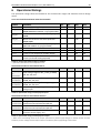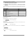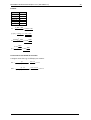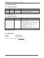
1
Hardware MCST 3601 Technical Manual W E CREATE MOTION EN Imprint Version: 1st edition, 01.10.2014 Copyright by FAULHABER PRECISTEP SA Rue des Gentianes 53 · 2300 La Chaux-de-Fonds · Switzerland All rights reserved, including those to the translation. No part of this description may be duplicated, reproduced, stored in an information system or processed or transferred in any other form without prior express written permission of FAULHABER PRECISTEP SA. This technical manual has been prepared with care. FAULHABER PRECISTEP SA cannot accept any liability for any errors in this technical manual or for the consequences of such errors. Equally, no liability can be accepted for direct or consequential damages resulting from improper use of the equipment. The relevant regulations regarding safety engineering and interference suppression as well as the requirements specified in this technical manual are to be noted and followed when using the software. Subject to change without notice. The respective current version of this technical manual is available on FAULHABER‘s internet site: www.faulhaber.com 2 MODULE Hardware Version V1.2 HARDWARE MANUAL + + MCST3601 1‐Axis Stepper Controller / Driver 3‐axes controller Master / Slave operation Up‐to 1 A / 36 V Incremental encoder input GPIOs + + UNIQUE FEATURES: - Compatible with the whole PRECIstep® stepper motor range Compact and fully programmable ASIC design POWERED BY: MCST3601 Hardware Manual (Rev. 0.91 / 2014‐MAY‐27) Table of Contents 1 2 3 Features ............................................................................................................................................ 5 Order Codes ...................................................................................................................................... 6 Mechanical and Electrical Interfacing ............................................................................................... 7 3.1 Dimensions and Mounting Holes ............................................................................................... 7 3.2 Connectors ................................................................................................................................. 8 3.2.1 Motor / Encoder connector .................................................................................................. 9 3.2.2 Power / Interface connector ...............................................................................................10 3.2.3 Motor Connector ................................................................................................................11 3.2.4 S/D 1 connector ..................................................................................................................11 3.2.5 S/D 2 connector ..................................................................................................................11 3.2.6 Mini‐USB connector ............................................................................................................12 3.3 Power Supply ...........................................................................................................................12 3.4 USB communication .................................................................................................................13 3.5 Inputs and Outputs ..................................................................................................................13 3.5.1 Reference and Home switch inputs ....................................................................................13 3.5.2 General purpose Inputs ......................................................................................................14 3.5.3 General purpose Outputs ...................................................................................................14 4 Motor driver current .......................................................................................................................15 5 Jumper .............................................................................................................................................19 6 Operational Ratings .........................................................................................................................20 7 MCST3601 Operational Description ................................................................................................21 7.1 Calculation: Velocity and Acceleration vs. Microstep and Fullstep Frequency .......................21 8 Revision History ...............................................................................................................................23 8.1 Document Revision ..................................................................................................................23 8.2 Hardware Revision ...................................................................................................................23 9 References .......................................................................................................................................23 4 MCST3601 Hardware Manual (Rev. 0.91 / 2014‐MAY‐27) 1 5 Features The MCST3601 is a single axis controller/driver module for 2‐phase bipolar stepper motors. It supports supply voltages up‐to 36V DC and motor currents up‐to 1A RMS (different motor current settings selectable in software and via two jumpers). The TMCL™ firmware allows for both, standalone operation and direct mode. The module can be configured as master (controller + driver) controlling up‐to two external drivers in addition to the on‐board one or as slave (driver only) with step/direction/enable inputs. MAIN CHARACTERISTICS Motion controller - Motion profile calculation in real‐time - On the fly alteration of motor parameters (e.g. position, velocity, acceleration) - High performance microcontroller for overall system control and serial communication protocol handling Bipolar stepper motor driver - Up to 256 microsteps per full step - High‐efficient operation, low power dissipation - Dynamic current control - Integrated protection Interfaces - USB device interface (on‐board mini‐USB connector) 6x open drain outputs (24V compatible) - REF_L / REF_R / HOME switch inputs (24V compatible with programmable pull‐ups) - 1x S/D input for the on‐board driver (on‐board motion controller can be deactivated) - 2x Step / direction output for two separate external drivers (in addition to the on‐board) - 1x encoder input for incremental a/b/n encoder - 3x general purpose digital inputs (24V compatible) - 1x analog input (0 .. 10V) Please note: not all functions are available at the same time as connector pins are shared Software - TMCL: standalone operation or remote controlled operation, program memory (non volatile) for up to 2048 TMCL commands, and PC‐based application development software TMCL‐IDE available for free. Electrical and mechanical data - Supply voltage: +24 V DC nominal (9… 36 V DC) - Motor current: up to 1 A RMS / 1.5 A peak (programmable) - Board size: 68mm + 47.5mm MCST3601 Hardware Manual (Rev. 0.91 / 2014‐MAY‐27) 2 Order Codes Order code MCST3601 MCST3601‐SK Size (mm3) Description Single axis bipolar stepper motor controller / driver electronics 68 x 47.5 x 13 Controller board with one add‐on electronics and one stepper 108 x 53 x 45 motor for quick demonstration and understanding. Table 2.1 Order codes 6 MCST3601 Hardware Manual (Rev. 0.91 / 2014‐MAY‐27) 3 7 Mechanical and Electrical Interfacing 3.1 Dimensions and Mounting Holes The dimensions of the controller/driver board are approx. 68 mm x 47.5 mm x 13 mm. Maximum component height (height above PCB level) without mating connectors is around 9mm above PCB level and 2 mm below PCB level. Figure 3.1 Dimension of MCST3601 and position of mounting holes MCST3601 Hardware Manual (Rev. 0.91 / 2014‐MAY‐27) 8 3.2 Connectors The controller/driver board MCST3601 offers two rows of screw connectors at each end of the pcb. There is one additional motor connector and two single row headers for step direction output for axis one and two (please note that the internal driver axis has the number 0). S/D 1 SD/2 Connector Connector 1 4 4 1 1 1 12 12 1 4 Motor Connector USB Connector Figure 3.2 Overview connectors Label Motor / Encoder connector Power / Interface connector Motor connector S/D 2 connector S/D 3 connector Mini‐USB Connector Connector type Mating connector type Screw connector Wire: up‐to 0.5 mm2 Screw connector Wire: up‐to 0.5 mm2 Molex PicoBlade, 4pin, 1.25mm pitch 53047‐0410 Single row header, 4pins, 2.54mm pitch Connector housing: Molex 51021‐0400 Contacts: Molex 50079‐8000 Wire: AWG 26‐28 Single row header, 4pins, 2.54mm pitch Molex 500075‐1517 Mini USB Type B vertical receptacle Table 3.1 Connectors and mating wires / connectors Single row female plug, 4pins 2.54mm pitch Single row female plug, 4pins 2.54mm pitch Any standard mini‐USB plug MCST3601 Hardware Manual (Rev. 0.91 / 2014‐MAY‐27) 9 3.2.1 Motor / Encoder connector 12 screw connectors located next to each other at one end of the board offer inputs for reference / home switches, an incremental a/b/n encoder including +5V encoder supply output and connection for the 2‐phase bipolar stepper motor. Pin 1 2 3 4 5 6 7 8 9 10 11 12 Label REF_L / DIR_IN REF_R / EN_IN HOME / STEP_IN ENC_A / IN1 ENC_B / IN2 ENC_N / IN3 Direc‐ tion Input Input Input Description Left stop switch input, programmable pull‐up to +5V or direction input in S/D operation mode Right stop switch input, programmable pull‐up to +5V or enable input in S/D operation mode Home switch input, programmable pull‐up to +5V or enable input in S/D operation mode Input Incremental encoder channel A input or digital input 1 Input Incremental encoder channel B input or digital input 2 Input Incremental encoder index / null channel I input or digital input 3 Power +5VOUT +5V / 100mA output Power GND (GND) Motor Output Phase A+ Motor Output Phase A‐ Motor Output Phase B+ Motor Output Phase B‐ +5V output. +5V generated from on‐board DC/DC‐ converter. Output can be switched on/off in software Signal and system ground Motor driver output (motor axis 0), coil A Motor driver output (motor axis 0), coil A Motor driver output (motor axis 0), coil B Motor driver output (motor axis 0), coil B Table 3.2 Connector for reference switches, encoder and motor CAUTION Do not connect or disconnect motor during operation! Motor cable and motor inductivity might lead to voltage spikes when the motor is disconnected / connected while energized. These voltage spikes might exceed voltage limits of the driver MOSFETs and might permanently damage them. Therefore, always disconnect power supply before connecting / disconnecting the motor. MCST3601 Hardware Manual (Rev. 0.91 / 2014‐MAY‐27) 10 3.2.2 Power / Interface connector 12 screw connectors located next to each other at the other end of the board include single power supply offer general purpose open‐drain outputs, an incremental a/b/n encoder including +5V encoder supply output and connection for a 2‐phase bipolar stepper motor.. Pin 1 Label GND Direction Power (GND) 2 +9V .. 36V DC Power (Supply in) 3 4 Reserved Reserved 5 OUT0 Output 6 OUT1 Output 7 OUT2 Output 8 OUT3 Output 9 OUT4 Output 10 OUT5 Output 11 IN0 Input 12 GND Power (GND) Description System and signal ground Power supply in. Common supply input for driver and logic part. All further required voltages are generated on‐board from this voltage Open drain output. Max. 100mA sink to ground capability with integrated freewheeling diode to power supply in Open drain output. Max. 100mA sink to ground capability with integrated freewheeling diode to power supply in Open drain output. Max. 100mA sink to ground capability with integrated freewheeling diode to power supply in Open drain output. Max. 100mA sink to ground capability with integrated freewheeling diode to power supply in Open drain output. Max. 100mA sink to ground capability with integrated freewheeling diode to power supply in Open drain output. Max. 100mA sink to ground capability with integrated freewheeling diode to power supply in Analog input (0 .. 10V), can be used as digital input, too. System and signal ground Table 3.3 Connector for power, analog input and general purpose digital outputs MCST3601 Hardware Manual (Rev. 0.91 / 2014‐MAY‐27) 11 3.2.3 Motor Connector A Molex PicoBlade™ 4pin 1.25mm pitch connector is available for motor connection (motor axis 0 in TMCL™ firmware). Please note: the 4 pins of this connector are directly connected to the motor driver output signals of the Motor / Encoder connector. Therefore, either use this connector or pin 9 to 12 of the Motor / Encoder connector for connecting a bipolar 2‐phase stepper motor. Pin 1 2 3 6 Label Motor Phase A+ Motor Phase A‐ Motor Phase B+ Motor Phase B‐ Direction Description Output Motor driver output, coil A Output Motor driver output, coil A Output Motor driver output, coil B Output Motor driver output, coil B Table 3.4 Motor connector CAUTION Do not connect or disconnect motor during operation! Motor cable and motor inductivity might lead to voltage spikes when the motor is disconnected / connected while energized. These voltage spikes might exceed voltage limits of the driver MOSFETs and might permanently damage them. Therefore, always disconnect power supply before connecting / disconnecting the motor. 3.2.4 S/D 1 connector A 4 pin single row header with 2.54mm pitch is used for Step/Direction out for motor axis 1 (motor 1 in TMCL™ firmware). Pin 1 2 3 4 Label DIR2 STEP2 EN2 GND Direction Output Output Output Power (GND) Description Direction output for motor axis 1 Step output for second motor axis Enable output for second motor axis Signal and supply ground Table 3.5 Connector for Step / Direction output for the second motor axis 3.2.5 S/D 2 connector A 4 pin single row header with 2.54mm pitch is used for Step/Direction out for motor axis 2 (motor 2 in TMCL™ firmware). Pin 1 2 3 4 Label DIR3 STEP3 EN3 GND Direction Output Output Output Power (GND) Description Direction output for motor axis 2 Step output for motor axis 2 Enable output for motor axis 2 Signal and supply ground Table 3.6 Connector for Step / Direction output for the third motor axis MCST3601 Hardware Manual (Rev. 0.91 / 2014‐MAY‐27) 12 3.2.6 Mini‐USB connector A 5pin mini‐USB connector is available on‐board for serial communication. This module supports USB 2.0 Full‐Speed (12Mbit/s) connections. Please note: - On‐board digital core logic (mainly processor and EEPROM) will be powered via USB in case no other supply is connected. This mode of operation can be used to set parameters / download TMCL programs or perform firmware updates with the module connected via USB only or inside the machine while the machine is powered off. Pin 1 2 3 4 5 Label VBUS D‐ D+ ID GND Direction Power (Supply input) Bidirectional Bidirectional Power (GND) Power (GND) Description +5V supply from host USB Data – USB Data + Connected to signal and system ground Connected to signal and system ground Table 3.7: Connector for USB 3.3 Power Supply For proper operation care has to be taken with regard to power supply concept and design. Due to space and especially height restrictions the MCST3601 includes just about 40µF / 50V of supply filter capacitors. These are ceramic capacitors which have been selected for high reliability and long life time. CAUTION Add external power supply capacitor! It is recommended to connect an electrolytic capacitor of significant size (e.g. 470µF/35V) to the power supply lines next to the MCST3601! Rule of thumb for size of electrolytic capacitor: c 1000 I In addition to power stabilization (buffer) and filtering this added capacitor will also reduce any voltage spikes which might otherwise occur from a combination of high inductance power supply wires and the ceramic capacitors. In addition it will limit slew‐rate of power supply voltage at the module. The low ESR of ceramic‐only filter capacitors may cause stability problems with some switching power supplies. Keep the power supply voltage below the upper limit of 36V! Otherwise the driver electronics might be seriously damaged! Especially, when the selected operating voltage is near the upper limit a regulated power supply is highly recommended. There is no reverse polarity protection! The module will short any reversed supply voltage due to internal diodes of the driver transistors. MCST3601 Hardware Manual (Rev. 0.91 / 2014‐MAY‐27) 13 3.4 USB communication For remote control and communication with a host system the MCST3601 provides a USB 2.0 full‐speed (12Mbit/s) interface (mini‐USB connector). As soon as a USB‐Host is connected the module will accept commands via USB. The MCST3601 support USB self powered operation (when an external power is supplied via the power supply connector) and USB bus powered operation (no external power supply via power supply connector). During USB bus powered operation, only the core digital circuit parts will be operational. That is, the microcontroller itself and also the EEPROM. Motor movements will not be possible. This mode has been implemented in order to enable configuration / parameter setting / read‐out, firmware updates etc. by just connecting a USB cable between the module and a host PC. No additional cabling / external devices as e.g. power supply etc. are required in that case. Please note that the module might draw current from the USB +5V bus supply even in USB self powered operation depending on the voltage level of this supply. 3.5 Inputs and Outputs 3.5.1 Reference and Home switch inputs All three reference and home switch inputs REF_L / REF_R and HOME offer the same input circuit with voltage resistor dividers, limiting diodes against over‐ and under‐voltage and programmable 1k pull‐ups to +5V. The programmable pull‐ups can be switched on or off together for all three inputs. Figure 3.4: Reference switch input circuit (simplified diagram) MCST3601 Hardware Manual (Rev. 0.91 / 2014‐MAY‐27) 14 3.5.2 General purpose Inputs The MCST3601 offers three general purpose digital inputs and one analog input. All inputs offer the same basic input protection circuit. The dedicated analog input has different input voltage dividers in order to support a full scale input voltage range of 0…+10V. The other digital inputs have been designed in order to be able to accept +5V and +24V signal levels. Figure 3.5: General purpose digital input circuit Figure 3.6: General purpose analog input circuit The function of the inputs might differ depending on firmware version. 3.5.3 General purpose Outputs The MCST3601 offers six general purpose outputs. All outputs are open‐drain outputs. For all outputs a freewheeling diode (to power supply) is already integrated. Figure 3.7: General purpose output (open‐drain with freewheeling diode) MCST3601 Hardware Manual (Rev. 0.91 / 2014‐MAY‐27) 4 15 Motor driver current The on‐board stepper motor driver operates current controlled. The driver current may be programmed in software for each motor axis individually in two ranges (0.5A RMS and 1A RMS) with 32 effective scaling steps in hardware for each range. In addition, via setting / closing two jumpers (see chapter 5) two lower current ranges () with 32 effective scaling steps in hardware for each range may be selected. Motor current measured for one phase with max. current settings (incl. both Jumpers closed) and 256 microsteps: CH1 (yellow): motor current [100mV / A] Motor current with both Jumpers set / closed: Motor current Range setting setting in in software software (TMCL) (TMCL) 0..7 1 8..15 1 16..23 1 24..31 1 32..39 1 40..47 1 48..55 1 56..63 1 64..71 1 72..79 1 80..87 1 88..95 1 96..103 1 104..111 1 112..119 1 120..127 1 128..135 1 136..143 1 144..151 1 Current scaling step (CS) 0 1 2 3 4 5 6 7 8 9 10 11 12 13 14 15 16 17 18 Motor current Ipeak [A] 0.025 0.051 0.076 0.102 0.127 0.152 0.178 0.203 0.228 0.254 0.279 0.305 0.330 0.355 0.381 0.406 0.432 0.457 0.482 Motor current IRMS [A] 0.018 0.036 0.054 0.072 0.090 0.108 0.126 0.144 0.162 0.180 0.197 0.215 0.233 0.251 0.269 0.287 0.305 0.323 0.341 MCST3601 Hardware Manual (Rev. 0.91 / 2014‐MAY‐27) Motor current Range setting setting in in software software (TMCL) (TMCL) 152..159 1 160..167 1 168..175 1 176..183 1 184..191 1 192..199 1 200..207 1 208..215 1 216..223 1 224..231 1 232..239 1 240..247 1 248..255 1 0..7 0 8..15 0 16..23 0 24..31 0 32..39 0 40..47 0 48..55 0 56..63 0 64..71 0 72..79 0 80..87 0 88..95 0 96..103 0 104..111 0 112..119 0 120..127 0 128..135 0 136..143 0 144..151 0 152..159 0 160..167 0 168..175 0 176..183 0 184..191 0 192..199 0 200..207 0 208..215 0 216..223 0 224..231 0 232..239 0 240..247 0 248..255 0 Current scaling step (CS) 16 Motor current Ipeak [A] 19 20 21 22 23 24 25 26 27 28 29 30 31 0 1 2 3 4 5 6 7 8 9 10 11 12 13 14 15 16 17 18 19 20 21 22 23 24 25 26 27 28 29 30 31 Motor current with both Jumpers removed / not closed: 0.508 0.533 0.558 0.584 0.609 0.635 0.660 0.685 0.711 0.736 0.762 0.787 0.812 0.047 0.094 0.141 0.188 0.235 0.282 0.328 0.375 0.422 0.469 0.516 0.563 0.610 0.657 0.704 0.751 0.798 0.845 0.892 0.938 0.985 1.032 1.079 1.126 1.173 1.220 1.267 1.314 1.361 1.408 1,455 1.502 Motor current IRMS [A] 0.359 0.377 0.395 0.413 0.431 0.449 0.467 0.485 0.503 0.521 0.539 0.556 0.574 0.033 0.066 0.100 0.133 0.166 0.199 0.232 0.265 0.299 0.332 0.365 0.398 0.431 0.465 0.498 0.531 0.564 0.597 0.630 0.664 0.697 0.730 0.763 0.796 0.830 0.863 0.896 0.929 0.962 0.995 1.029 1.062 MCST3601 Hardware Manual (Rev. 0.91 / 2014‐MAY‐27) 17 Motor current Range setting setting in in software software (TMCL) (TMCL) 0..7 1 8..15 1 16..23 1 24..31 1 32..39 1 40..47 1 48..55 1 56..63 1 64..71 1 72..79 1 80..87 1 88..95 1 96..103 1 104..111 1 112..119 1 120..127 1 128..135 1 136..143 1 144..151 1 152..159 1 160..167 1 168..175 1 176..183 1 184..191 1 192..199 1 200..207 1 208..215 1 216..223 1 224..231 1 232..239 1 240..247 1 248..255 1 0..7 0 8..15 0 16..23 0 24..31 0 32..39 0 40..47 0 48..55 0 56..63 0 64..71 0 72..79 0 80..87 0 88..95 0 96..103 0 104..111 0 112..119 0 Current scaling step (CS) 0 1 2 3 4 5 6 7 8 9 10 11 12 13 14 15 16 17 18 19 20 21 22 23 24 25 26 27 28 29 30 31 0 1 2 3 4 5 6 7 8 9 10 11 12 13 14 Motor current Ipeak [A] 0.006 0.013 0.019 0.025 0.031 0.038 0.044 0.050 0.057 0.063 0.069 0.075 0.082 0.088 0.094 0.101 0.107 0.113 0.119 0.126 0.132 0.138 0.145 0.151 0.157 0.163 0.170 0.176 0.182 0.189 0.195 0.201 0.012 0.023 0.035 0.046 0.058 0.070 0.081 0.093 0.105 0.116 0.128 0.139 0.151 0.163 0.174 Motor current IRMS [A] 0.004 0.009 0.013 0.018 0.022 0.027 0.031 0.036 0.040 0.044 0.049 0.053 0.058 0.062 0.067 0.071 0.076 0.080 0.084 0.089 0.093 0.098 0.102 0.107 0.111 0.116 0.120 0.124 0.129 0.133 0.138 0.142 0.033 0.016 0.025 0.033 0.041 0.049 0.058 0.066 0.074 0.082 0.090 0.099 0.107 0.115 0.123 MCST3601 Hardware Manual (Rev. 0.91 / 2014‐MAY‐27) Motor current Range setting setting in in software software (TMCL) (TMCL) 120..127 0 128..135 0 136..143 0 144..151 0 152..159 0 160..167 0 168..175 0 176..183 0 184..191 0 192..199 0 200..207 0 208..215 0 216..223 0 224..231 0 232..239 0 240..247 0 248..255 0 Current scaling step (CS) 15 16 17 18 19 20 21 22 23 24 25 26 27 28 29 30 31 18 Motor current Ipeak [A] 0.186 0.198 0.209 0.221 0.232 0.244 0.256 0.267 0.279 0.291 0.302 0.314 0.325 0.337 0.349 0.360 0.372 Motor current IRMS [A] 0.132 0.140 0.148 0.156 0.164 0.173 0.181 0.189 0.197 0.205 0.214 0.222 0.230 0.238 0.247 0.255 0.263 Motor current setting in software (TMCL) These are the values for TMCL axis parameter 6 (motor run current) and 7 (motor standby current). They are used to set the run / standby current using the following TMCL commands: SAP 6, <motor number 0..5>, <value> // set run current SAP 7, <motor number 0..5>, <value> // set standby current Range setting in software (TMCL) For <value> numbers between 0 and 255 are supported (see table) (read‐out value with GAP instead of SAP. Please see separate MCST3601 TMCL™ firmware manual for further information) This is the value for TMCL axis parameter 179 (Vsense). This value defines the current range. This value can be set using the following TMCL command: SAP 179, <motor number 0..5>, <value> // = 0 high current range // = 1 low current range Motor current IRMS [A] For <value> either 0 or 1 is supported (see table) (read‐out value with GAP instead of SAP. Please see separate MCST3601 TMCL™ firmware manual for further information) Resulting motor current based on range and motor current setting In addition to the settings in the table the motor current may be switched off completely (free‐ wheeling) individually for each motor using axis parameter 204 (see MCST3601 TMCL™ firmware manual). MCST3601 Hardware Manual (Rev. 0.91 / 2014‐MAY‐27) 5 19 Jumper The MCST3601 offers 2 on‐board Jumpers for selection of two different motor current ranges: Jumpers Jumper Description Max. motor current 1A RMS / 1.5A peak (with VSENSE = 0 (programmable)) Closed Max. motor current 0.57A RMS / 0.8A peak (with VSENSE = 1 (programmable)) Max. motor current 0.26A RMS / 0.37A peak (with VSENSE = 0 (programmable)) Open Max. motor current 0.14A RMS / 0.20A peak (with VSENSE = 1 (programmable)) Table 5.1 Jumper Please note: it is mandatory to either set both jumpers or leave both jumpers unpopulated. CAUTION Do not remove / install jumpers while module is powered‐on! MCST3601 Hardware Manual (Rev. 0.91 / 2014‐MAY‐27) 6 20 Operational Ratings The operational ratings show the intended or the characteristic ranges and should be used as design values. In no case shall the maximum values be exceeded! Symbol Parameter Min Typ Max Unit VDD ICOIL_peak ICOIL_RMS ICOIL_peak ICOIL_RMS IDD IUSB I+5VOUT TENV Power supply voltage for operation Motor coil current for sine wave peak with jumper closed and VSENSE = 0 (programmable) Continuous motor current (RMS) with jumper closed Motor coil current for sine wave peak with jumper open Continuous motor current (RMS) with jumper open and VSENSE = 0 (programmable) Power supply current USB supply current in USB powered‐mode current at +5V output (for encoder supply) Environment temperature at maximum rated current (no forced cooling required) +9 12… 24 +36 1.6 V A 1.1 A 0.39 A 0.27 A ‐30*) << ICOIL 50 1.4 * ICOIL 100 40*) A mA mA °C Min Typ Max Unit 0 30 V 1.2 V 3.2 V 0 10.3 V Min Typ Max Table 6.1 General operational ratings of module *) preliminary data based on basic temperature tests. OPERATIONAL RATINGS OF MULTIPURPOSE INPUTS Symbol VREF_L/REF_R/HO ME/ IN0/IN1/IN2/IN3 VREF_L/REF_R/HO ME/ IN1/IN2/IN3_L VREF_L/REF_R/HO ME/ IN1/IN2/IN3_H VIN0 Parameter Input voltage range for REF_L, REF_R, HOME, IN0, IN1, IN2, IN3 Low level input voltage for REF_L, REF_R, HOME, IN1, IN2, IN3 High level input voltage for REF_L, REF_R, HOME, IN1, IN2, IN3 Full scale input voltage range for analog voltage input Table 6.2 Operational ratings of multipurpose Inputs OPERATIONAL RATINGS OF MULTIPURPOSE OUTPUTS Symbol VOUT1/OUT2/OUT3 / OUT4/OUT5/OUT6 IOUT1/OUT2/OUT3/ OUT4/OUT5/OUT6 I+5VOUT Parameter Voltage at open drain outputs OUT0/OUT1/OUT2/OUT3/OUT4/OUT5 Output sink current of open drain outputs OUT0/OUT1/OUT2/OUT3/OUT4/OUT5 Current at +5V output (for encoder, active reference switch supply, etc.) Unit 1) +VDD V 100 mA 100 mA Table 6.3 Operational ratings of multipurpose Outputs 1) Please note: free‐wheeling diodes for all outputs (connected to positive supply voltage) are already included on‐board. Therefore, the nom. voltage at these outputs should not exceed the power supply voltage of this module. MCST3601 Hardware Manual (Rev. 0.91 / 2014‐MAY‐27) 7 21 MCST3601 Operational Description 7.1 Calculation: Velocity and Acceleration vs. Microstep and Fullstep Frequency The values of the parameters sent to the TMC429 do not have typical motor values like rotations per second as velocity. But these values can be calculated from the TMC429 parameters as shown in this section. PARAMETERS OF TMC429 Signal Description Range fCLK Clock‐frequency 16 MHz velocity ‐ 0… 2047 a_max Maximum acceleration 0… 2047 Divider for the velocity. The higher the value is, the less is pulse_div the maximum velocity 0… 13 default value = 0 Divider for the acceleration. The higher the value is, the ramp_div less is the maximum acceleration 0… 13 default value = 0 0… 8 (a value of 7 or 8 is internally Usrs Microstep‐resolution (microsteps per fullstep = 2usrs) mapped to 6 by the TMC429) Table 7.1 TMC429 velocity parameters MICROSTEP FREQUENCY The microstep frequency of the stepper motor is calculated with usf [ Hz ] f CLK [ Hz ] velocity 2 pulse _ div 2048 32 with usf: microstep‐frequency FULLSTEP FREQUENCY To calculate the fullstep frequency from the microstep frequency, the microstep frequency must be divided by the number of microsteps per fullstep. fsf [ Hz ] usf [ Hz ] 2 usrs with fsf: fullstep‐frequency The change in the pulse rate per time unit (pulse frequency change per second – the acceleration a) is given by a 2 f CLK 2 a max pulse _ div ramp _ div 29 This results in acceleration in fullsteps of: a af 2 usrs with af: acceleration in fullsteps MCST3601 Hardware Manual (Rev. 0.91 / 2014‐MAY‐27) EXAMPLE: Signal f_CLK velocity a_max pulse_div ramp_div usrs value 16 MHz 1000 1000 1 1 6 msf 16 MHz 1000 122070 .31 Hz 2 1 2048 32 122070 .31 fsf [ Hz ] 26 1907 .34 Hz a (16Mhz) 2 1000 11 29 2 119.21 MHz s MHz s 1.863 MHz 6 s 2 119.21 af CALCULATION OF THE NUMBER OF ROTATIONS A stepper motor has e.g. 72 fullsteps per rotation. RPS fsf 1907 . 34 26 . 49 fullsteps per rotation 72 RPM fsf 60 1907 . 34 60 1589 .46 fullsteps per rotation 72 22 MCST3601 Hardware Manual (Rev. 0.91 / 2014‐MAY‐27) 8 23 Revision History 8.1 Document Revision Version 0.90 0.91 0.92 Date 2013‐OCT‐01 2014‐MAY‐ 27 2014‐SEP‐12 Author GE GE DWI Description Initial draft version Update for hardware version 1.1 Current settings (chapter 4) added Update pictures Table 9.1 Document revision 8.2 Hardware Revision Version TMCM‐1114‐FH_V10 MCST3601_V11 Date 2013‐JUL‐30 2014‐MAR‐28 MCST3601_V12 2014‐JUL‐09 Description First version USB powered option added (air wire from previous version removed) Board size changed, labels added next to connector Motor numbers in silk screen changed (to be compatible with TMCL™ IDE Varistors at driver output added for better protection Board renamed in MCST3601 Solderstop blue, connectors Amphenol (black) CAN information suppressed Table 9.2 Hardware revision 9 References [TMC262] TMC262 Datasheet [TMC429] TMC429 Datasheet [TMCL‐IDE] TMCL‐IDE User Manual For further information, please refer to www.trinamic.com FAULHABER PRECISTEP SA 7000.55001 English, 1st edition, 10.2014 © FAULHABER PRECISTEP SA Subject to change without notice Rue des Gentianes 53 2300 La Chaux-de-Fonds Switzerland Tel. +41 32 910 6050 Fax +41 32 910 6059 [email protected] www.faulhaber.com