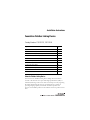
1
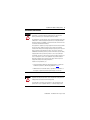
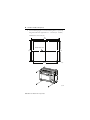
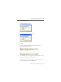
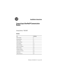
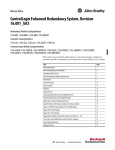
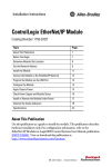
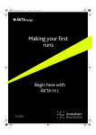
Installation Instructions
Foundation Fieldbus Linking Device
Catalog Numbers 1757-FFLD2, 1757-FFLD4
Topic
Page
Important User Information
2
Environment and Enclosure
3
North American Hazardous Location Approval
4
European Hazardous Location Approval
5
Parts Illustration of the Fieldbus Linking Device
6
Install the Linking Device
7
Wire the Linking Device
11
Configure the Linking Device
14
Troubleshoot the Linking Device
18
Specifications
21
Additional Resources
26
About the Fieldbus Linking Device
The FOUNDATION Fieldbus Linking Device bridges from the Ethernet
network to H1 networks. It accepts either High-speed Ethernet (HSE) or
EtherNet/IP messages and converts them to the H1 protocol. By supporting
H1, HSE, and EtherNet/IP protocols, the linking device is capable of
providing bridging capability of Rockwell Automation products and
FOUNDATION Fieldbus products on the Ethernet network to products on H1
links.
2 Foundation Fieldbus Linking Device
Important User Information
Solid state equipment has operational characteristics differing from those of electromechanical
equipment. Safety Guidelines for the Application, Installation and Maintenance of Solid State Controls
(Publication SGI-1.1 available from your local Rockwell Automation sales office or online at
http://www.literature.rockwellautomation.com) describes some important differences between solid
state equipment and hard-wired electromechanical devices. Because of this difference, and also
because of the wide variety of uses for solid state equipment, all persons responsible for applying this
equipment must satisfy themselves that each intended application of this equipment is acceptable.
In no event will Rockwell Automation, Inc. be responsible or liable for indirect or consequential damages
resulting from the use or application of this equipment.
The examples and diagrams in this manual are included solely for illustrative purposes. Because of the
many variables and requirements associated with any particular installation, Rockwell Automation, Inc.
cannot assume responsibility or liability for actual use based on the examples and diagrams.
No patent liability is assumed by Rockwell Automation, Inc. with respect to use of information, circuits,
equipment, or software described in this manual.
Reproduction of the contents of this manual, in whole or in part, without written permission of Rockwell
Automation, Inc., is prohibited.
Throughout this manual, when necessary, we use notes to make you aware of safety considerations.
WARNING
IMPORTANT
ATTENTION
Identifies information about practices or circumstances that can cause an
explosion in a hazardous environment, which may lead to personal injury or
death, property damage, or economic loss.
Identifies information that is critical for successful application and understanding
of the product.
Identifies information about practices or circumstances that can lead to personal
injury or death, property damage, or economic loss. Attentions help you identify a
hazard, avoid a hazard and recognize the consequences.
SHOCK HAZARD
Labels may be on or inside the equipment, for example, drive or motor, to alert
people that dangerous voltage may be present.
BURN HAZARD
Labels may be on or inside the equipment, for example, drive or motor, to alert
people that surfaces may reach dangerous temperatures.
Publication 1757-IN021E-EN-P - August 2009
Foundation Fieldbus Linking Device 3
Environment and Enclosure
ATTENTION
This equipment is intended for use in a Pollution Degree 2 industrial
environment, in overvoltage Category II applications (as defined in IEC
60664-1), at altitudes up to 2000 m (6562 ft) without derating.
This equipment is considered Group 1, Class A industrial equipment according
to IEC/CISPR 11. Without appropriate precautions, there may be difficulties
with electromagnetic compatibility in residential and other environments due
to conducted and radiated disturbances.
This equipment is supplied as open-type equipment. It must be mounted within
an enclosure that is suitably designed for those specific environmental
conditions that will be present and appropriately designed to prevent personal
injury resulting from accessibility to live parts. The enclosure must have
suitable flame-retardant properties to prevent or minimize the spread of flame,
complying with a flame spread rating of 5VA, V2, V1, V0 (or equivalent) if
non-metallic. The interior of the enclosure must be accessible only by the use
of a tool. Subsequent sections of this publication may contain additional
information regarding specific enclosure type ratings that are required to
comply with certain product safety certifications.
In addition to this publication, see:
• Industrial Automation Wiring and Grounding Guidelines, for additional
installation requirements, Allen-Bradley publication 1770-4.1.
• NEMA Standards 250 and IEC 60529, as applicable, for explanations of
the degrees of protection provided by different types of enclosure.
ATTENTION
To comply with the CE Low Voltage Directive (LVD), all connections to this
equipment must be powered from a source compliant with safety extra low
voltage (SELV) or protected extra low voltage (PELV).
To comply with UL restrictions, all connections to this equipment must be
powered from a source compliant with Class 2 or limited voltage/current.
Publication 1757-IN021E-EN-P - August 2009
4 Foundation Fieldbus Linking Device
North American Hazardous Location Approval
The following information applies when
operating this equipment in hazardous
locations.
Informations sur l’utilisation de cet
équipement en environnements dangereux.
Products marked "CL I, DIV 2, GP A, B, C, D" are suitable for
use in Class I Division 2 Groups A, B, C, D, Hazardous
Locations and nonhazardous locations only. Each product is
supplied with markings on the rating nameplate indicating
the hazardous location temperature code. When
combining products within a system, the most adverse
temperature code (lowest "T" number) may be used to help
determine the overall temperature code of the system.
Combinations of equipment in your system are subject to
investigation by the local Authority Having Jurisdiction at
the time of installation.
Les produits marqués "CL I, DIV 2, GP A, B, C, D" ne
conviennent qu'à une utilisation en environnements de
Classe I Division 2 Groupes A, B, C, D dangereux et non
dangereux. Chaque produit est livré avec des marquages sur
sa plaque d'identification qui indiquent le code de
température pour les environnements dangereux. Lorsque
plusieurs produits sont combinés dans un système, le code de
température le plus défavorable (code de température le plus
faible) peut être utilisé pour déterminer le code de
température global du système. Les combinaisons
d'équipements dans le système sont sujettes à inspection par
les autorités locales qualifiées au moment de l'installation.
WARNING
EXPLOSION HAZARD • Do not disconnect equipment unless
power has been removed or the
area is known to be nonhazardous.
• Do not disconnect connections to
this equipment unless power has
been removed or the area is known
to be nonhazardous. Secure any
external connections that mate to
this equipment by using screws,
sliding latches, threaded
connectors, or other means
provided with this product.
• Substitution of components may
impair suitability for Class I,
Division 2.
• If this product contains batteries,
they must only be changed in an
area known to be nonhazardous.
Publication 1757-IN021E-EN-P - August 2009
AVERTISSEMENT
RISQUE D’EXPLOSION –
• Couper le courant ou s'assurer
que l'environnement est classé
non dangereux avant de
débrancher l'équipement.
• Couper le courant ou s'assurer
que l'environnement est classé
non dangereux avant de
débrancher les connecteurs. Fixer
tous les connecteurs externes
reliés à cet équipement à l'aide
de vis, loquets coulissants,
connecteurs filetés ou autres
moyens fournis avec ce produit.
• La substitution de composants
peut rendre cet équipement
inadapté à une utilisation en
environnement de Classe I,
Division 2.
• S'assurer que l'environnement est
classé non dangereux avant de
changer les piles.
Foundation Fieldbus Linking Device 5
European Hazardous Location Approval
European Zone 2 Certification (The following applies when the product bears the Ex or EEx
marking.)
This equipment is intended for use in potentially explosive atmospheres as defined by European Union Directive 94/9/EC.
Intertek certifies that this equipment has been found to comply with the Essential Health and Safety Requirements relating
to the design and construction of Category 3 equipment intended for use in potentially explosive atmospheres, given in
Annex II to this Directive. The examination and test results are recorded in confidential report 3172640DAL.
Compliance with the Essential Health and Safety Requirements has been assured by compliance with EN 60079-15 and
EN 60079-0.
WARNING
• This equipment must be installed in an enclosure providing at least IP54
protection when applied in Zone 2 environments.
• This equipment is not resistant to sunlight or other sources of UV
radiation.
• This equipment shall be used within its specified ratings defined by
Allen-Bradley.
• Provision shall be made to prevent the rated voltage from being exceeded
by transient disturbances of more than 40% when applied in Zone 2
environments.
• Secure any external connections that mate to this equipment by using
screws, sliding latches, threaded connectors, or other means provided
with this product.
• Do not disconnect equipment unless power has been removed or the area
is known to be nonhazardous.
Preventing Electrostatic Discharge
ATTENTION
This equipment is sensitive to electrostatic discharge, which can cause
internal damage and affect normal operation. Follow these guidelines when
you handle this equipment:
• Touch a grounded object to discharge potential static.
•
•
•
•
•
Wear an approved grounding wriststrap.
Do not touch connectors or pins on component boards.
Do not touch circuit components inside the equipment.
Use a static-safe workstation, if available.
Store the equipment in appropriate static-safe packaging when not in
use.
Publication 1757-IN021E-EN-P - August 2009
6 Foundation Fieldbus Linking Device
Parts Illustration of the Fieldbus Linking Device
The sample illustration shows the parts that comprise the 1757-FFLD linking
device, which links Rockwell Automation products and FOUNDATION
Fieldbus products on the Ethernet network to products on H1 links.
1
2
3
6
4
7
5
8
9
10
31989-M
Feature
Description
1
Reset configuration jumper
2
Factory-default reset button (inside top cover)
3
Interface to expansion I/O, removable ESD sticker
4
H1 status indicators
5
Status indicators
6
Fieldbus H1 interface terminals
7
Filler module
8
Power supply connection (not shown)
9
Ethernet port (not shown)
10
Serial port (not used)
Publication 1757-IN021E-EN-P - August 2009
Foundation Fieldbus Linking Device 7
Before You Begin
The following software is compatible with this revision of the linking device:
•
•
•
•
RSFieldbus software, version 2.03 or later
RSLogix 5000 programming software, version 16.03 or later
RSLinx Classic software, version 2.52 or later
Logix5000 Clock Update tool
Install the Linking Device
Install your linking device by using the instructions on the following pages.
Mount the Linking Device
Most applications require installation in an industrial enclosure (Pollution
Degree 2) to reduce the effects of electrical interference (Over Voltage
Category II) and environmental exposure. Locate your linking device as far as
possible from power lines, load lines, and other sources of electrical noise
such as hard-contact switches, relays, and AC motor drives. For more
information on proper grounding guidelines, see the Industrial Automation
Wiring and Grounding Guidelines, publication 1770-4.1.
ATTENTION
• We do not recommend vertical mounting due to heat build-up
considerations.
• Be careful of metal chips when drilling mounting holes for your linking
device or other equipment within the enclosure or panel. Drilled
fragments that fall into the unit could cause damage.
Publication 1757-IN021E-EN-P - August 2009
8 Foundation Fieldbus Linking Device
Product Dimensions
Dimension
Measurement
Height (A)
138 mm (5.43 in.)
Width (B)
168 mm (6.62 in.)
Depth (C)
87 mm (3.43 in.)
A
B
C
43481
Mount on a DIN Rail
The linking device DIN-rail latch locks in the open position so that the
linking device can be easily attached to or removed from the DIN rail. The
maximum extension of the latch is 15 mm (0.67 in.) in the open position. You
need a screwdriver to remove the linking device. The linking device can be
mounted to 35 x 7.5 or 35 x 15 DIN rails (EN 50 022). See page 10 for
DIN-rail mounting dimensions.
ATTENTION
This product is grounded through the DIN rail to chassis ground. Use zinc
plated yellow-chromate steel DIN rail to assure proper grounding. The use of
other DIN rail materials (for example, aluminum or plastic) that can corrode,
oxidize, or are poor conductors can result in improper or intermittent
grounding. Secure DIN rail to the mounting surface approximately every
200 mm (7.8 in.) and use end-anchors appropriately.
Do these steps to install your linking device on the DIN rail.
1. Verify that the placement of the linking device on the DIN rail allows
for 50 mm (2 in.) of space on all sides for adequate ventilation.
2. Hook the top slot over the DIN rail.
Publication 1757-IN021E-EN-P - August 2009
Foundation Fieldbus Linking Device 9
3. While pressing the linking device down against the top of the rail,
snap the bottom of the linking device into position.
Top Slot
B
Middle of DIN
DIN Rail
A
C
43482
Dimension
Height
A
138 mm (5.43 in.)
B
69 mm (2.715 in.)
C
69 mm (2.715 in.) DIN latch closed, 76.1 mm (3 in.) DIN latch open
Mount on a Panel
Follow these steps to install your linking device on a panel.
1. Verify that the placement of the linking device allows for
50 mm (2 in.) of space on all sides for adequate ventilation.
Publication 1757-IN021E-EN-P - August 2009
10 Foundation Fieldbus Linking Device
2. Use the following figures to mount the linking device to a panel by
using #8 or M4 screws tightened to 1.1…1.8 N•m (10…16 lb•in).
All dimensions are in mm (in.).
168
(6.62)
DIN Rail Center Line
132
(5.19)
122
(4.813)
147
(5.78)
43580
31991-M
Publication 1757-IN021E-EN-P - August 2009
Foundation Fieldbus Linking Device 11
Wire the Linking Device
Wire your linking device by using these instructions.
WARNING
• If you connect or disconnect wiring while the field-side power is on, an
electrical arc can occur. This could cause an explosion in hazardous
location installations. Be sure that power is removed or the area is
nonhazardous before proceeding.
• When you change switch settings while power is on, an electrical arc can
occur. This could cause an explosion in hazardous location installations.
Be sure that power is removed or the area is nonhazardous before
proceeding.
Wire Requirements
The FOUNDATION Fieldbus recommendation for the cable connecting
fieldbus devices is 0.8 mm2 (18 AWG) shielded, twisted-pair wire. It is
important to calculate how the planned topology for your fieldbus segment,
selected wiring, supplied power, and intended mix of fieldbus devices may
impact the overall performance of a fieldbus network.
For further details, see:
• the FOUNDATION Fieldbus specifications at http://www.fieldbus.org,
publication AG-140
• the Fieldbus Solutions for Rockwell Automation’s Integrated
Architecture User Manual, publication 1757-UM006, for a condensed
overview of fieldbus wiring considerations.
Publication 1757-IN021E-EN-P - August 2009
12 Foundation Fieldbus Linking Device
Ethernet Connection
WARNING
If you connect or disconnect the communication cable with power applied to
this module or any device on the network, an electrical arc can occur. This
could cause an explosion in hazardous location installations. Be sure that
power is removed or the area is nonhazardous before proceeding
Connect your Ethernet cable to the Ethernet port on the underside of the
linking device. The factory default for the linking device is Dynamic Host
Configuration Protocol (DHCP) for initial configuration.
H1 Terminal Block
WARNING
ATTENTION
IMPORTANT
When you connect or disconnect the removable terminal block (RTB) with
field-side power applied, an electrical arc can occur. This could cause an
explosion in hazardous location installations. Be sure that power is removed or
the area is nonhazardous before proceeding.
Be careful when stripping wires. Wire fragments that fall into the linking
device could cause damage.
The H1 terminal plugs are keyed so they fit only into the corresponding
socket. Be certain that you are connecting the cables to the correct plugs.
The linking device provides two parallel terminals on each H1 network. Use
one to connect to your fieldbus devices and use the other for short-term
connection of diagnostic devices.
Perform the following steps to connect the H1 cables.
1. Strip about 5…7 mm (0.2…0.28 in.) of the insulation at the ends of
the cable leads.
2. Insert the stripped cable end into the RTB, following the layout on
page 13, and tighten the screw.
Publication 1757-IN021E-EN-P - August 2009
Foundation Fieldbus Linking Device 13
3. Complete step 1 and step 2 for all H1 cables.
4. Insert the RTB into the corresponding socket.
H1 Terminal Block Layout (catalog number 1757-FFLD4 shown)
+ - + - + - + H1-1
+ - + - + - + -
H1-2
H1-3
H1-4
Power and Grounding
IMPORTANT
You must use a power conditioner between your fieldbus power supply and
the devices on the fieldbus network. For more information, see the
FOUNDATION Fieldbus specifications at http://www.fieldbus.org,
publication AG-140
Do not exceed 10 m (32.8 ft) total wiring length on the 24V DC power
connection.
1. Connect the chassis ground to connector 1 - CHASSIS GND.
2. Connect the 24V common to connector 2 - DC GND.
3. Connect the +24V DC input power to connector 3 - 24V DC (+20%).
1
CHASSIS GND
2
DC Gnd
3
24V DC (+20%)
43576
4. Apply power to the linking device.
Publication 1757-IN021E-EN-P - August 2009
14 Foundation Fieldbus Linking Device
Configure the Linking Device
The following instructions describe how to configure and set up network
parameters for your linking device.
Assign an IP Address
The Rockwell Automation BOOTP/DHCP Server (BOOTP) is a standalone
program that combines the functionality of standard BOOTP software with
DHCP software. The linking device is shipped with DHCP enabled.
To configure the linking device by using BOOTP, perform the
following steps.
1. Choose Start > Programs > Rockwell Software > BOOTP-DHCP
Server 2.3.2 Standalone > BOOTP-DHCP Server 2.3.2 Standalone.
BOOTP opens and the linking device sends a request.
2. Verify that the linking device is the correct device by matching the
MAC address with the MAC address found on the label of the linking
device (under the barcode).
Publication 1757-IN021E-EN-P - August 2009
Foundation Fieldbus Linking Device 15
3. Double-click the request.
A New Entry dialog box opens.
4. Type the IP address for the linking device.
5. Click OK.
The device is added to the Relation List at the bottom of the
BOOTP/DHCP Server window.
6. To permanently assign this configuration to the linking device, select
the device and click Disable BOOTP/DHCP.
When you cycle power to the linking device, it uses the configuration
you assigned and does not issue a DHCP request.
Publication 1757-IN021E-EN-P - August 2009
16 Foundation Fieldbus Linking Device
7. To enable DHCP for the linking device, select the device and click
Enable DHCP.
Save the Relation List
You can save the Relation List for later use. Do these steps to save the
Relation List.
1. From the File menu, choose Save As.
The Save dialog box opens.
2. Choose the location to save in.
3. Type a File name for the Relation List (for example, ‘Control System
Configuration’) and click Save.
Install the EDS File
The EDS file can be uploaded directly from the linking device. This feature
lets you register the EDS file for your device from within RSLinx software by
following the steps listed below.
1. Open RSLinx software, and browse for the linking device.
2. Right-click the linking device and choose Upload EDS file from
the device.
3. Complete the EDS wizard to register the EDS file.
The EDS file can also be downloaded from
http://www.ab.com/networks/eds.html and installed with the RSLinx EDS
Hardware Installation tool.
Publication 1757-IN021E-EN-P - August 2009
Foundation Fieldbus Linking Device 17
Set the Linking Device’s Network Parameters
1. Open RSLinx software and click the RSWho icon.
2. Browse to the linking device under the Ethernet/IP driver.
3. Right-click the linking device and choose Module Configuration to set
network parameters.
Publication 1757-IN021E-EN-P - August 2009
18 Foundation Fieldbus Linking Device
4. Click the Port Configuration tab to view or change parameters.
5. When you finish making changes, click Apply and then OK.
Troubleshoot the Linking Device
The following instructions describe how to maintain your linking device.
Reset the Linking Device
You can reset the linking device with the:
• reset jumper (locally).
• reset button (locally).
• web page (remotely).
To use the reset jumper or reset button, follow the procedures below. To use
the web page, refer to the FOUNDATION Fieldbus Linking Device User
Manual, publication 1757-UM010.
You can reset the linking device to the following defaults:
• Reset Configuration
• Factory
Publication 1757-IN021E-EN-P - August 2009
Foundation Fieldbus Linking Device 19
Reset Configuration
The Reset Configuration removes power from the battery, clearing all
downloaded fieldbus configurations. The linking device retains its network
configuration and web page password information through this reset.
Do these steps to reset configuration.
1. Remove power from the linking device.
WARNING
If you insert or remove the jumper while the power is on, an electrical arc can
occur. This could cause an explosion in hazardous location installations. Be
sure the area is nonhazardous before proceeding.
2. Move the jumper from its original position (two right pins) to the two
left pins.
3. Wait 5 seconds.
4. Move the jumper back to its original position.
5. Return power to the linking device.
Reset to Factory Default
The factory-default reset sets the linking device’s network configuration to use
BOOTP, erases web page password information, and clears all downloaded
fieldbus configurations. Follow these steps to complete a factory-default reset.
1. Verify that the linking device is powered up and in a running state
(H1 status indicators are blinking).
2. Press the reset button.
WARNING
When you press the reset button while power is on, an electrical arc can occur.
This could cause an explosion in hazardous location installations. Be sure that
power is removed or the area is nonhazardous before proceeding.
Publication 1757-IN021E-EN-P - August 2009
20 Foundation Fieldbus Linking Device
Status Indicators
Linking Device Status Indicators
Indicator
Status
Description
H1
Off
The linking device H1 channel is inactive.
Verify that the linking device is connected to the H1 network.
Flashing green The linking device H1 channel is active.
STATUS
(module)
Off
No power - Module does not have 24V DC power.
Verify that power is supplied to the module.
Flashing green Standby - Module not configured.(1)
Green
Operational - Module operating correctly.
Flashing red
Minor fault - A recoverable fault has been detected.
Verify that the configuration is correct and consistent.
Red
Major fault - An unrecoverable fault has been detected.
Recycle power to the module. If this does not clear the fault,
replace the module.
WDOG
Off
(watchdog) Flashing red
BATT
(battery)
Off
Flashing red
Normal operation.
Software fault.
Contact Rockwell Automation Technical Support.
Normal operation.
Jumper is missing (or not seated on the two rightmost pins), or
the battery is low or dead.(2)
NS
(network
status)
Off
Not powered, no IP address.
Verify that power is supplied or assign an IP address.
Flashing green No connections.(1)
Verify that the linking device is connected to the fieldbus
network.
Green
CIP connections.
Flashing red
Connection timeout.
Verify that the linking device is connected to the Ethernet
network.
Flashing red
and green
Self test.
Publication 1757-IN021E-EN-P - August 2009
Foundation Fieldbus Linking Device 21
Linking Device Status Indicators
Indicator
Status
Description
MODE
Solid green
Linking device operational.
Flashing green Linking device out-of-service.
Verify that the Resource Block is set to Target Auto mode.
(1)
If you already set the IP address and the Status and Mode indicators are flashing green, you may have
a duplicate IP address with another device on your network.
(2)
If the BATT status indicator remains on after the jumper is replaced, and power has been returned to
the linking device, contact Rockwell Automation Technical Support.
Specifications
1757-FFLD2, 1757-FFLD4 - Technical Specifications
Attribute
Value
Physical interfaces
2 or 4 H1 FOUNDATION Fieldbus interfaces
1 10/100 Ethernet interface (HSE, IP)
Number of H1 networks(1) per linking device
2 for 1757-FFLD2 linking device, 4 for
1757-FFLD4 linking device
Number of fieldbus devices per H1
network, max
16 (8…10 recommended)
Number of fieldbus devices per linking
device, max
64
Power requirements
Current rating/supply power
In rush current
300 mA @ 24V DC (± 20%)
1.5 A
Isolation voltage
50V (continuous), Basic Insulation Type,
Fieldbus to system backplane and Ethernet
network to system backplane
Type tested at 500V AC for 60 s
Panel mounting screw torque
(using M4 or #8 screws)
1.1…1.8 N•m (10…16 lb•in)
Publication 1757-IN021E-EN-P - August 2009
22 Foundation Fieldbus Linking Device
1757-FFLD2, 1757-FFLD4 - Technical Specifications
Attribute
Value
Wiring category(2)
2 - on Fieldbus ports
3 - on power ports
2 - on Ethernet ports
Terminal block torque specifications
0.34 N•m (3 lb•in) on power and Fieldbus
wire connections
Wire size
DC power connection
0.2... 1.5 mm2 (26...16 AWG) solid or
stranded copper wire rated at 75 °C (167 °F)
or greater 1.2 mm (3/64 in.) insulation max
Fieldbus connections
0.8 mm2 (18 AWG) solid or stranded
shielded twisted pair copper wire rated at
75 °C (167 °F) or greater 1.2 mm (3/64 in.)
insulation max
Ethernet connections
RJ45 connector according to IEC 60603-7,
2 or 4 pair Category 5e minimum cable
according to TIA 568-B.1 or Category 5
cable according to ISO/IEC 24702
Program retention (unpowered)
21 days
North American temp code
T4
IEC temp code
T4
In-circuit battery life
5000 charge/discharge cycles (about 13
years). Battery is not replaceable
Enclosure type rating
None (open-style)
(1)
Each network defined as a FOUNDATION Fieldbus 31.25 kbps H1 network.
(2)
Use this Conductor Category information for planning conductor routing. Refer to Industrial
Automation Wiring and Grounding Guidelines, publication 1770-4.1.
Publication 1757-IN021E-EN-P - August 2009
Foundation Fieldbus Linking Device 23
1757-FFLD2, 1757-FFLD4 - Environmental Specifications
Attribute
Value
Operating temperature
0…60 °C (32…140 °F)
IEC 60068-2-1 (Test Ad, Operating Cold)
IEC 60068-2-2 (Test Bd, Operating Dry Heat)
IEC 60068-2-14 (Test Nb, Operating Thermal
Shock)
Nonoperating temperature
-40…85 °C (-40…185 °F)
IEC 60068-2-1 (Test Ab, Unpackaged
Nonoperating Cold)
IEC 60068-2-2 (Test Bb, Unpackaged
Nonoperating Dry Heat)
IEC 60068-2-14 (Test Na, Unpackaged
Thermal Shock)
Relative humidity
5…95% noncondensing
IEC 60068-2-30 (Test Db, Unpackaged
Damp Heat)
Vibration
5 g @ 10…500 Hz
IEC 60068-2-6 (Test Fc, Operating)
Operating shock
15 g
IEC 60068-2-27 (Test Ea, Unpackaged
Shock)
Nonoperating shock
30 g
IEC 60068-2-27 (Test Ea, Unpackaged
Shock)
Emissions
Group 1, Class A
CISPR 11
ESD immunity
6 kV contact discharges
IEC 61000-4-2
8 kV air discharges
Publication 1757-IN021E-EN-P - August 2009
24 Foundation Fieldbus Linking Device
1757-FFLD2, 1757-FFLD4 - Environmental Specifications
Attribute
Value
Radiated RF immunity
1V/m with 1 kHz sine-wave 80% AM from
2000…2700 MHz
IEC 61000-4-3
10V/m with 1 kHz sine-wave 80% AM from
80…2000 MHz
10V/m with 200 Hz 50% Pulse 100% AM at
900 MHz and 1890 MHz
EFT/B immunity
±2 kV at 5 kHz on power ports
IEC 61000-4-4
±2 kV at 5 kHz on shielded Fieldbus ports
±2 kV at 5 kHz on Ethernet ports
Surge transient immunity
IEC 61000-4-5
±2 kV line-earth (CM) on shielded Fieldbus
ports
±2 kV line-earth (CM) on shielded Ethernet
ports
Conducted RF immunity
IEC 61000-4-6
Magnetic field immunity
10V rms with 1 kHz sine-wave 80% AM
from 150 kHz…80 MHz on power ports,
shielded Fieldbus ports, and Ethernet ports
30 A/m long duration at 50 Hz
IEC 61000-4-8
1757-FFLD2, 1757-FFLD4 - Certifications(1)
Certification (2)
Value
c-UL-us
UL Listed for Class I, Division 2 Group
A,B,C,D Hazardous Locations, certified for
U.S. and Canada. See UL File E194810.
Publication 1757-IN021E-EN-P - August 2009
Foundation Fieldbus Linking Device 25
1757-FFLD2, 1757-FFLD4 - Certifications(1)
Certification (2)
Value
CE
European Union 2004/108/EC EMC
Directive, compliant with:
• EN 61326-1; Meas./Control/Lab.,
Industrial Requirements
• EN 61000-6-2; Industrial Immunity
• EN 61000-6-4; Industrial Emissions
• EN 61131-2; Programmable
Controllers (Clause 8, Zone A & B)
C-Tick
Australian Radiocommunications Act,
compliant with:
• AS/NZS CISPR 11; Industrial
Emissions
Ex
European Union 94/9/EC ATEX Directive,
compliant with:
• EN 60079-15; Potentially Explosive
Atmospheres, Protection "n"
• EN 60079-0; General Requirements
• II 3 G Ex nA nL IIC
EtherNet/IP
ODVA conformance tested to EtherNet/IP
specifications
FF
FOUNDATION Fieldbus Test Campaigns
H1-CT0060, HTK-000900
(1)
When product is marked.
(2)
See the Product Certification link at http://www.ab.com for Declarations of Conformity, Certificates,
and other certification details.
Publication 1757-IN021E-EN-P - August 2009
26 Foundation Fieldbus Linking Device
Additional Resources
These documents contain additional information concerning related Rockwell
Automation products.
Resource
Description
FOUNDATION Fieldbus Wiring and Installation
Application Guide publication at
http://www.fieldbus.org, publication
AG-140
Provides information on how to wire, power,
and configure network components.
FOUNDATION Fieldbus Intrinsic Safe Systems
Application Guide at
http://www.fieldbus.org, publication
AG-163
Introduces you to the principals of intrinsic
safety, and outlines how to apply approved
devices in a hazardous area.
FOUNDATION Fieldbus Linking Device User
Manual, publication 1757-UM010
Provides information needed to use the
linking device, including function block and
web page details.
Fieldbus Solutions for Rockwell
Automation’s Integrated Architecture User
Manual, publication 1757-UM006
Overview of intergrating fieldbus into
ProcessLogix, ControlLogix, and PLC-5
controllers.
Publication 1757-IN021E-EN-P - August 2009
Foundation Fieldbus Linking Device 27
Notes:
Publication 1757-IN021E-EN-P - August 2009
Rockwell Automation Support
Rockwell Automation provides technical information on the Web to assist you in using
its products. At http://www.support.rockwellautomation.com you can find technical
manuals, a knowledge base of FAQs, technical and application notes, sample code and
links to software service packs, and a MySupport feature that you can customize to
make the best use of these tools.
For an additional level of technical phone support for installation, configuration, and
troubleshooting, we offer TechConnect support programs. For more information,
contact your local distributor or Rockwell Automation representative, or visit
http://www.support.rockwellautomation.com.
Installation Assistance
If you experience a problem within the first 24 hours of installation, please review the
information that's contained in this manual. You can also contact a special Customer
Support number for initial help in getting your product up and running.
United States
1.440.646.3434
Monday – Friday, 8 a.m. – 5 p.m. EST
Outside United States
Please contact your local Rockwell Automation representative for any
technical support issues.
New Product Satisfaction Return
Rockwell Automation tests all of its products to ensure that they are fully operational
when shipped from the manufacturing facility. However, if your product is not
functioning and needs to be returned, follow these procedures.
United States
Contact your distributor. You must provide a Customer Support case number
(call the phone number above to obtain one) to your distributor to complete
the return process.
Outside United States
Please contact your local Rockwell Automation representative for the return
procedure.
Allen-Bradley, Rockwell Automation, ControlLogix, RSLogix 5000, RSLinx Classic, Logix5000, Rockwell Software,
PLC-5, ProcessLogix, RSFieldbus, RSLinx, and TechConnect are trademarks of Rockwell Automation, Inc.
Trademarks not belonging to Rockwell Automation are property of their respective companies.
Publication 1757-IN021E-EN-P - August 2009
Supersedes Publication 1757-IN021D-EN-P - October 2005
PN-45236
Copyright © 2009 Rockwell Automation, Inc. All rights reserved. Printed in the U.S.A.