1
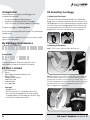
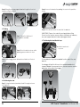
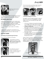
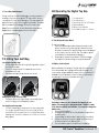
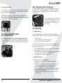
User Manual
VERSION 1.1
Contents
Thank you for purchasing the MGI Quad
series motorised buggy. To get the most
out of your buggy please follow these
quick steps before use.
•
•
•
Register your buggy online [section 1.0]
Charge your battery [section 4.0]
Assemble your buggy [section 3.0]
For Customer Support, please contact MGI directly
for immediate and professional advice.
Email: [email protected]
LIVE chat: visit www.mgigolf.com
Toll Free within Australia: 1300 644 523 (excludes mobiles)
Western Australia / International Phone: +61 3 8872 6700
Local Service Centres: visit www.mgigolf.com to locate
your local service centre.
NOTE: This user manual was correct at time of printing. The online
version is the most up-to-date and must be referred to as the
correct version. To download the most current user manual
please visit www.mgigolf.com
1.0
2.0
3.0
3.1
3.2
3.3
3.4
3.5
3.6
3.7
3.8
4.0
4.1
4.2
4.3
5.0
6.0
6.1
6.2
6.3
7.0
8.0
8.1
8.2
8.3
8.4
8.5
8.6
8.7
8.8
9.0
10.0
11.0
11.1
11.2
11.3
12.0
12.1
12.2
12.3
12.4
12.5
12.6
13.0
14.0
15.0
16.0
Registration
What’s Included
Assembling Your buggy
Attaching the Front Wheels
Attaching the Rear Wheels
Rear Wheel Positions
Unfolding
Folding
Positioning the Seat
Positioning the Sand Bucket Loop
Attaching the Umbrella Holder
Battery Care
Charging Your Battery
Tips and Looking After Your Battery
Plugging in the Battery
Battery Fuse
Front Wheels
Unlocking, Locking and Removing
the Front Wheels
Adjusting and Aligning the Front Wheels
Front Wheel Maintenance
Fitting Your Golf Bag
Operating the Top Box
On/Off Speed Control Button
Battery Level Indicator
Electronic Park Brake
Downhill Speed Control
Units Measurements
Distance Modes
Controlled Distance Function [CDF]
Competition Mode
Integrated GPS Holder
and Compartment
Integrated Solar charging
Warranty
Warranty Policy
Warranty Exclusions
Parts Installed During Warranty
Preventative Maintenance Program
Cleaning Your MGI Quad Buggy
Rear Wheel Axles Maintenance
Upper and Lower Bag Strap
Maintenance
Correcting the Alignment
MGI Service Schedule
Service Recording
Service and Repair Centres
Purchasing Parts and Accessories
Contact MGI
Frequently Asked Questions
04
04
05
05
05
06
07
08
08
09
10
10
10
11
11
12
12
13
13
14
14
15
15
15
16
16
16
16
17
18
18
19
19
19
19
20
20
20
21
21
21
21
23
24
24
24
25
MGI Coaster™ Quad Brake User Manual 03
1.0 Registration
It is most important you register your MGI Buggy online
immediately as registration:
•
•
•
Records your buggy for warranty purposes
Speeds up any servicing required on your buggy
Assist us to contact you with any updates to your buggy
To register your buggy, visit www.mgigolf.com
3.0 Assembling Your Buggy
3.1 Attaching the Front Wheels
The two front wheels need to be attached to your MGI Quad
Buggy. There is no difference between each front wheel so either
can be placed on the left or right side. Simply line up the silver pin
on the front wheel with the buggy and push into the frame until
you hear a positive click. You can test the wheel is in position by
pulling firmly on the wheel. It should not move out of position.
You will need to record your MGI serial number. This is found under
the battery tray.
Please keep this user manual on file for your own reference and a
copy of your serial number;
My MGI Buggy Serial Number is
[example ACQV01234567890 ]
3.2 Attaching the Rear Wheels
Step 1. On the wheel, slide the release button across.
Purchased Date
/ /
You may be required to show proof of purchase so we
recommend you keep your receipt with this manual.
2.0 What’s Included
•
•
•
•
•
•
•
•
MGI Quad Buggy
Battery
Battery Bag and Lead [SLA batteries Only]
Battery Charger
Padded Seat with Bracket
Sand Bucket Loop
Umbrella Holder
Lower Bag Strap
•
Spare parts
– Speed Button x 1 – 40A Fuse Connector x 1 [see battery care section]
– 4mm Allen Key [for aligning front wheel as required]
– 4 x Rubber Gaskets for the rotating front wheel housing
[see front wheel maintenance section]
04
Step 2. You will notice you need to match up the inner female slot
of the axle and the male of the wheel. When placed in position
simply release the button. You will notice you hear a “click” when
the wheel is properly secured. To check that the wheel is properly
in position pull on the wheel. If it is properly in position it will not
slide off. Repeat for the right wheel.
MGI Coaster™ Quad Brake User Manual 05
3.3 Rear Wheels Positions
The MGI Quad buggy is designed to allow the rear wheels to be
in two positions. The position is determined by where the wheel is
locked on the axle in either of the two grooves [see picture]. The
drive position is used during the normal operation of the buggy.
The free wheel position is used to freely push the buggy should
you experience battery or service issues on the course.
Free wheel position
3.4 Unfolding
Step 1: Ensure both rear and front
wheels are attached.
Step 2: Release fold lever 1.
Drive position
i. Drive position – Lock the wheel onto the groove closest to the
battery tray. To do this, while sliding the release button on the
wheel across, push the wheel on to the axle as far as possible. To
test for drive position trying rolling the wheel forward. If you feel
resistance then the wheel is now in drive position and ready to
use. Repeat for both wheels.
Step 3: Slide fold lever 2 upwards
to release the handle.
Step 4: The handle is now free to pull upwards. The buggy will
naturally unfold as you continue to pull upwards until the buggy
is completely open.
ii. Free wheel – Lock the wheel into the groove furthest from the
battery tray. To do this, while sliding the release button across
on the wheel, push the wheel on to the axle and release the
release button onto the groove. To test for free wheel position
try rolling the wheel forward. The wheel should spin freely with no
resistance. Repeat for both wheels.
Step 5: Close the fold lever 2 to lock the handle into place.
06
MGI Coaster™ Quad Brake User Manual 07
Step 6: Bring the top bag support brackets together, then lock
together using the button.
3.5 Folding
Step 2: Secure the bracket by adding the screw in the position
shown.
Step 3: You can now insert the seat into the bracket.
Step 1: Open the fold lever 2
to release the handle.
IMPORTANT: Depress the seat with your hand before sitting.
Do not use the seat on uneven surfaces. MGI does not warranty
any seat support brackets that are damaged or bent.
3.7 Positioning the Sand Bucket Loop
Add the Sand Bucket
Loop here.
Step 2: Press the button shown while
applying pressure down to close.
Step 3: Lower buggy down flat and close fold lever 2 to lock
handle.
The Sand bucket loop can be added to other end of the seat
bracket.
Your buggy will look like this once the seat and sand bucket
loop are added. For personal choice, these accessories can be
placed on either side of the buggy.
3.6 Positioning the Seat
Step 1: Using the bracket provided, feed it through as shown
in the picture.
08
MGI Coaster™ Quad Brake User Manual 09
3.8 Attaching the Umbrella Holder
•
The umbrella holder is attached to the frame using the largest
bolt. Screw this into the frame as shown in the picture.
•
•
•
•
•
Your umbrella holder can be
adjusted both to the side,
backwards and forwards. The
umbrella is secured inside the
umbrella holder by tightening the
plastic bolt located near the top of
the holder.
IMPORTANT: Do not leave your
Umbrella up in the holder in windy
conditions. If the wind catches the
umbrella, it could cause your buggy
to tip over and cause damage,
which will not be covered by
warranty.
4.0 Battery Care
4.1 Before using your MGI Quad buggy for the first time you must
fully charge your battery overnight.
The Coaster Quad Brake is designed to take a range of batteries:
• 28 amp/hr SLA [sealed lead acid] battery
• MGI’s Lithium Ion 12 volt batteries.
To charge your battery:
• Unplug the battery from your buggy [after play].
• Plug the charger into a power point,
• Plug the charger into the battery.
There are lights on the charger to help you understand the
charging process.
The Green LED illuminates to indicate the charger
is power on.
The Red LED indicates the battery is charging.
The LED will turn Green when the battery is fully charged.
The LED will flash Green when the battery is on float charge.
The Red LED will flash is there is a fault with the charger.
The 12v SLA charger will power off automatically after being
on float charge for three hours. The 12v lithium ion charger
will power off automatically after being on float charge for
18 hours.
4.2 Tips and Important Information About Charging Your Battery
•
•
•
•
Always recharge the battery as soon as possible after use,
no matter how short the period of use. Leaving your battery
uncharged will only reduce the life of the battery.
Your battery will charge best, lying flat, in a warm and air
flowing location.
In winter, it is best charged off any concrete floor and
preferably in a warm location within the house.
The charger is a smart digital charger and will not over
charge your battery. Therefore in between use, always leave
the charger connected to the battery with power on.
Looking after your battery during play and travel
• During play, minimise the drain on the battery by avoiding
taking your buggy into the rough whenever possible.
• Avoid using the buggy to pull you up the hills
• If you are intending to take your buggy and battery on a
flight, we advise that you make contact with your airline prior
to travel.
• Be very careful not to drop your battery. The battery casing
is easily cracked and the battery’s subsequent life will be
severely compromised.
• Do not carry the battery by the leads, but use the carry bag
strap or built in strap.
• Do not submerge the battery in water.
Please refer to the Battery Charger User Manual for a complete
list of important information.
4.3 Plugging Your Battery into the Buggy
Step 1: Place the battery into the
universal battery tray.
10
MGI Coaster™ Quad Brake User Manual 11
The front wheels can be removed by pressing the blue button
shown in the picture and pulling the wheel down until it is
completely removed from the buggy.
Step 2: Plug the battery into the
buggy as shown.
Your buggy has been equipped with fail safe battery connection,
so the buggy will not move when you plug the battery in. Your
buggy will only start once the speed control is switched on.
5.0 Battery Lead Fuse
Your battery has a 40amp fuse connected to the battery lead.
The 40 amp fuse helps protect the buggy’s control board against
a power surge. An extra fuse is supplied with your buggy.
In the unlikelihood of your buggy stopping, the reason could be
the fuse has blown. Replacing the fuse is simple.
The fuse is located on the positive lead close to the battery
terminal.
6.2 Adjusting and Aligning the Front Wheels
Each buggy is checked for straight tracking prior to leaving the
factory. In the unlikely event the Quad buggy is not tracking
straight, the front wheels can be adjusted to regain straight
tracking as follows;
1.
2.
3.
To replace the fuse, simply open the case and remove the
existing fuse with a pair of pliers. Insert the new fuse ensuring the
two feet are guided into their sleeves. Refit the fuse cap.
4.
6.0 Front wheels
6.1 .Unlocking, Locking and Removing the Front Wheels
The front swivel wheel can be set in two positions.
1)Unlocked position to allow for
360deg swivel for optimum turning
ability. In the picture shown the two
blue components are aligned. This is
the position for unlocked.
2) Locked position is best when
using the Controlled Distance
Function. In the picture the two blue
components are now manually
moved apart.
12
Lock the two swivelling front wheels and start the buggy to
see if the buggy veers left or right. Please note that you can
swap the left and right front wheel and check again whether
the buggy is tracking straight.
Unlock the swivelling front wheels, swivel them to see the two
adjusting bolts in the front wheel, as below Picture 2.
If the buggy veers left, use the 4mm Allen Key provided in the
Quad free spare parts to screw the right bolts (in both front
wheels) clockwise and/or the left bolts (as shown in below
picture 2) anti clockwise.
If the buggy veers right, use the 4mm Allen Key provided in
the Quad free spare parts to screw the right bolts (in both
front wheels) anti clockwise and/or the left bolts (as shown in
below picture 2) clockwise.
Please note that there is a process in adjusting the track as above
point 3 and 4. It is suggested that the users should do a little bit
of adjustment, test the tracking and then adjust again until the
buggy goes straight. After the buggy tracks straight, do not swap
the left and right front wheels.
Left Bolt
Right Bolt
MGI Coaster™ Quad Brake User Manual 13
6.3 Front Wheel Maintenance
During the life of the MGI Quad buggy, you may experience
wearing of the front wheel gasket. This may result in a noise
coming from the front wheel during use. You can replace this
gasket at home using 1 of the 4 gaskets included in the spare
parts included with your buggy. Follow these easy steps
Step 1: Remove the front wheel following the steps above.
Step 2: Place the rubber gasket over the wheel pin.
8.0 Operating the Digital Top Box
4.
5.
6.
1.
3.
2.
1. Control button 1
2. Control button 2
3. Speed Control ON / OFF button
4. Speed indicator
5. Battery level indicator
6. S-SLA battery type / L – Lithium
8.1 On/Off Speed Control Button
7.0 Fitting Your Golf Bag
Securing the top bag strap
• Provide a good position for the positioning of both ends of
the elasticised straps
• Stretch the longer end of the strap and secure to the
extended shorter end
• The attached strap should now be connected
Adjusting the length of the top strap
• The plastic bar on the longer length can be adjusted to
ensure the bag is secured properly in place.
Securing the lower bag strap
• The MGI Quad buggy is designed so the lower bag strap
is no longer required. However the lower strap has been
included for your own preference. It is easily attached by
clipping each end of the strap into the eyelets on the lower
bag support.
14
To start your buggy:
1. Preset your desired speed by rotating the speed control
button clockwise to increase speed, or anticlockwise to
decrease the speed. The speed setting chosen is displayed
on the colour screen on the left side. Then tap the speed
control button to start and stop the buggy, or
2. Simply tap the speed control button to start the buggy,
then adjust the speed settings to your desired speed.
8.2 Battery Level Indicator
Battery indication is located on the right side of the top screen.
Four coloured bars are highlighted showing full charge. The
lesser number of bars displayed, means there is less battery life
available. You should always check the battery status before
you play golf to ensure the four bars are there.
The battery indicator is set to measure the capacity of your
battery. The battery type is displayed with an L [lithium] or and S
[SLA] under the battery level indicator. If you need to change the
battery type:
1. Disconnect the battery
2. Hold down the button to the Control button 2 [right of the
Speed Control]
3. Keep holding the button down, and connect the battery
4. Release the button, then press it again to shift between L
for Lithium and S for SLA battery type.
5. Once the battery type is set disconnect the battery.
MGI Coaster™ Quad Brake User Manual 15
8.3 Electronic Park Brake
2.
The MGI Coaster Quad has an Electronic Park Brake [EPB] which
when activated, stops the buggy from creeping forward on a hilly
terrain.
Distance Total: cannot be reset as it is the Odometer for the
life of the buggy. This feature will assist with service reminders
which are recommended at each 500kms or 6 months
periods.
To activate the Electronic Park Brake press and hold the Control
button 2 for 3 seconds. The digital screen will display the words
STOP on the screen.
To release the Electronic Park Brake simply tap the speed control
button and the buggy will resume movement.
Tips on using the Electronic Park Brake
• The EPB will consume battery power when in use
• Only use the EPB on large slopes when the buggy cannot
stand still by simply stopping the buggy.
• Do not use the EPB on flat surfaces to conserve battery life.
• The EPB function should not be ON for a long period of time.
• Simply use the on/off control when stopping on flat terrain or
during longer breaks on the course.
8.4 Downhill Speed Control
The downhill speed control feature is activated automatically
as the buggy enters a downhill incline. This feature is enhanced,
when compared to the Hunter Quad, because of the differential
gearbox.
Tips on understanding the Downhill Speed Control
• It is best to turn the speed down to a low speed before
entering the downhill terrain.
• The buggy may gain some speed downhill but will not
increase beyond control.
8.7 Controlled Distance Function [CDF]
The CDF enables the MGI Quad buggy to be sent a preset
distance before the buggy auto stops. To use this function:
1.
2.
3.
4.
5.
It is recommended that you lock the front wheels to ensure
the buggy tracks in a straight line.
Press and hold down Speed control button for 3-4 seconds
until the speed setting changes to 10 [5 yards or metres] and
the letter “A” appears
Turn the Speed control button clockwise to increase the
distance or anti-clockwise to decrease the distance until the
desired distance is achieved between 10-60 [metres or yards]
Always look ahead and assess the condition of the terrain of
where you want to send your buggy prior to doing so
Once the desired distance is reached, press the Speed
control button once to send the buggy off to the desired
distance.
8.5 Unit Measurements
You can move from kilometres to miles simply by pressing the
Control button 2 [on the right]
8.6 Distance Modes
There are three distance measurements. To move between the
modes by pressing the Control button 1 [on the left]
1.
16
Distance A and B: resettable distance measurements could be
used to measure how far you hit your shot and to measure
how far you have walked for the day. To reset, simply press
the Control button [left side] 1 for 3 seconds until the reading
displays “0”.
MGI Coaster™ Quad Brake User Manual 17
8.8 Competition Mode
In the unlikely event the club you are playing at does not allow
the use of distance devices you will need to disable the distances
feature on the MGI Quad buggy.
10.0 Integrated Solar Charging
An optional Solar Charger accessory is available to fit into the
top handle of the MGI Quad buggy. Once installed, the MGI
Quad is fitted with a charging cable located in the top hand
compartment.
To disable the distance recording feature, simply hold down the
two control buttons at the same time for 3 seconds. By doing
this the distance recording will be removed from the screen and
replaced with the words “Comp Mode”.
On the purchase of a Solar Charger,
you will receive adaptors to use
this cable to recharge any GPS or
mobile device while sitting in the
GPS holder.
11.0 Warranty
11.1 Warranty Policy
9.0 Integrated GPS Holder
and Compartment
In the top handle compartment is an integrated GPS/mobile
device holder. To open the holder the holder always press the
Coloured button at the top of the holder. Place the GPS into the
cradle, then close the holder by squeezing the two sides closer
together.
The MGI Quad buggy is covered by a Limited* manufacturer’s
warranty from the date of purchase. Duration of this warranty is:
•
•
•
2 years on parts*
2 years on Lithium batteries and chargers
1 year on SLA batteries and chargers
* MGI or an authorised service centre will repair or replace any
parts found to be defective in materials or workmanship under
normal use provided that:
1.
2.
3.
The MGI Quad buggy has been properly used, maintained
and regularly serviced [see section 12]
The replacement or repair is performed by an authorised MGI
service centre or the owner with MGI approval.
The buggy has been registered online.
11.2 Warranty Exclusions
The following events will void warranty:
• Any alteration performed by non authorised people or
companies.
• Fitting of parts or accessories not recommended by MGI.
• Any damage caused by continued operation of the
motorised buggy after it is known to be defective.
• Damage to seat and/or seat support bracket on buggy
• Damage caused by ingress of water into motor/gearbox
and other major components
• Damage caused by buggy going into bunkers and other
course hazards
18
MGI Coaster™ Quad Brake User Manual 19
All implied warranties [save those preserved by statute] are
excluded. Liability for consequential damages under any and all
warranties are excluded to the extent exclusion is permitted by
law.
11.3 Parts Installed During Warranty
Warranty coverage for components installed during a motorised
buggy’s warranty period shall consist of the duration of the
buggy’s warranty period, provided the warranty installation is
performed by MGI, an authorised service centre or the buggy
owner on approval. Replacement of parts under warranty will not
extend the warranty of the buggy or parts.
12.0 Preventative Maintenance Program
To properly provide for the continued operation of your MGI
Quad buggy, MGI has introduced its Preventative Maintenance
Program [PMP]. The PMP consists of work to be carried out
by both the owner and authorised service centres. To properly
maintain the warranty of your MGI motorised buggy, it is essential
that this work is carried out. If the work carried out by the
authorised service centre is to replace parts that are part of the
maintenance schedule, the owner will be charged for the parts
and labour. If the work to be carried out is part of warranty, MGI
will bear the cost.
12.1 Cleaning Your MGI Quad Buggy [See Maintenance Schedule]
For years of good operation, your buggy requires care and
attention.
• Keep your buggy clean by using a cloth with warm water
and a mild detergent.
• Do not hose down your buggy under any circumstance, as
your buggy has electronic components.
• Ensure that the seat stem bracket is free from sand.
• Do not submerge your buggy in water as it will cause
irreparable damage.
20
12.2 Rear Wheel Axles Maintenance [See Maintenance Schedule]
The rear wheel stub axles need to be lubricated regularly. Remove
the rear wheels by depressing the spring clip and at the same
time pull off the wheel. Apply Petroleum Jelly or light grease to
the stub axles. Use a very small amount as the grease can attract
sand. If you play in sandy conditions you should clean your axle
and regrease fortnightly.
12.3 Upper and Lower Bag Strap Maintenance
[See Maintenance Schedule]
The bag straps should be replaced as per the Service Schedule.
The upper bag strap can be replaced by:
•
•
•
•
Removing the left and right hand straps form the upper bag
support
Undo and remove the screws holding the strap in position
on the bag support
Remove and replace both bag straps
Insert bag strap securing screws
12.4 Correcting the Alignment
See the front wheel alignment in Section 6.2.
12.5 MGI Service Schedule
It is the owner’s responsibility to ensure that all periodical checks,
necessary adjustments and services are carried out. If in doubt
please contact the MGI service centre on 1300 644 523. Any work
performed on your buggy should be recorded on your service
record (see page 5) regardless of the work.
MGI Coaster™ Quad Brake User Manual 21
MGI Hunter and
Coaster Quad
Monthly
Wipe down the
buggy with a warm
cloth after each use
[do not hose]
BO
Lubricate rear wheel
stub axles
BO
6
Monthly
Check and tighten
nuts and bolts
BO /SC
Check and tighten
handle pivots
BO/SC
Check alignment of
buggy – ensure that
it runs straight
BO /SC
Replace fused SLA
battery leads
Every
2 yrs
Every
3 yrs
6 month inspection
Date:
Invoice #:
Serviced by:
Signature:
1 year inspection
Date:
Invoice #:
Serviced by:
Signature:
1 ½ year inspection
Date:
Invoice #:
Serviced by:
Signature:
2 year inspection
Date:
Invoice #:
Serviced by:
Signature:
2 ½ year inspection
Date:
Invoice #:
Serviced by:
Signature:
3 year inspection
Date:
Invoice #:
Serviced by:
Signature:
3 ½ year inspection
Date:
Invoice #:
Serviced by:
Signature:
4 year inspection
Date:
Invoice #:
Serviced by:
Signature:
4 ½ year inspection
Date:
Invoice #:
Serviced by:
Signature:
5 year inspection
Date:
Invoice #:
Serviced by:
Signature:
5 ½ year inspection
Date:
Invoice #:
Serviced by:
Signature:
6 year inspection
Date:
Invoice #:
Serviced by:
Signature:
BO/SC
Replace Speed
Control button
BO/SC
Replace speed
controller and On/
Off switch assembly
BO/SC
Replace rear and
front wheels
BO
Replace upper and
lower bag straps
BO
BO = Buggy owner can carry out this work
SC = Charged work to be carried by approved service centre
BO/SC = The six monthly service can be completed by either an
authorised service centre or the owner of the buggy.
22
12. 7 Service Record for All Buggies
MGI Coaster™ Quad Brake User Manual 23
13.0 Service and Repair Centres
16.0 FAQ
For all servicing, please do not go back to your place
of purchase.
Q: My battery level indicator on screen is not accurate.
A: You may need to tell your buggy whether you are using
a Lithium or standard SLA battery. See section 7.2 Battery
Indication to correct the type of battery you are using.
MGI offers the largest network of Service Centres in Australia
and New Zealand. To find your nearest Service centre visit
www.mgigolf.com
For warranty repairs to be authorised you MUST provide proof of
purchase. Please keep this with you as well as your Serial number
you can record in this manual.
14.0 Purchasing Parts and Accessories
You are welcome to service your buggy out of warranty,
by purchasing parts direct from MGI. Please call or email
to discuss the right parts and instructions.
15.0 Contacting MGI
MGI Golf Head Office
Address:
11 Maurice Court, Nunawading VIC Australia 3131
Phone: + 61 3 8872 6700
Local Toll Free: 1300 644 523 (excludes mobiles)
Email: [email protected] Web: www.mgigolf.com
24
Q: The front wheel is noisy in operation.
A: You may need to change the front wheel gasket caused
from wear and tear. See section 5.3 Front wheel maintenance
Q: My buggy is not tracking straight.
A: You can do a simple realignment on the two front wheels.
See section 5.2 Adjusting and aligning the front wheels
Q: Why does my MGI Quad buggy no longer have
a lower bag strap?
A: The MGI Quad buggy has been designed so the lower bag
strap is no longer required. If you would prefer one for personal
reasons, the lower bag strap is included with the spare parts
when the buggy was purchased
Q: I would like to have my MGI Quad buggy serviced.
Who do I call?
A: visit www.mgigolf.com to find your nearest Service centre
using your postcode within Australian and New Zealand.
You can also call MGI Head office using any of the contact
details. See Section 15 for details.
MGI Coaster™ Quad Brake User Manual 25
26
MGI Coaster™ Quad Brake User Manual 27
www.mgigolf.com
MGI Golf
P: +61 3 8872 6700 E: [email protected]
Follow us on