1
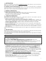
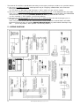
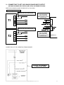
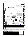
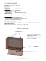
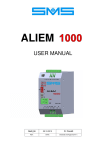
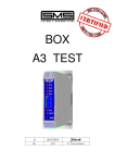
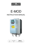
RED – H
INSTRUCTION MANUAL
6
01-12-2011
REL.
DATE
T.M. Check and Approval
CONTENTS
1 - INTRODUCTION ......................................................................... ........Page 3
2 - GENERAL DESCRIPTION ..................................................................Page 3
3 - OPERATION PRINCIPLE ...................................................................Page 3
4 - INSTALLATION ...................................................................................Page 3
5 - WIRING DIAGRAM .............................................................................Page 4
6 - OPTIONAL CONNECTIONS ...............................................................Page 5
7 - CONNECTING TO GET 230V THREE-PHASE OUTPUT ...................Page 5
8 - CONNECTING TO GET 400V SINGLE-PHASE OUTPUT ..................Page 6
9 - CONNECTING TO GET 230V SINGLE-PHASE INPUT/OUTPUT .......Page 7
10 - FINAL TEST AND INSPECTION .........................................................Page 8
11 - REDH BOARD LAYOUT .....................................................................Page 9
12 - TECHNICAL FEATURES ....................................................................Page 10
2
RED-H INTRUCTION MANUAL Release 6 date 01-12-2011
1 – INTRODUCTION
RED-H is an emergency rescue device for hydraulic lift systems, which allows the car to come back to
bottom floor and the car doors opening during black out.
It is supplied by a battery voltage 24Vdc (N°2 batteries 12V 7Ah series connected) and it is easy-fitting to
any kind of lift system, new or already existing.
This manual contains the necessary information about the connections, the put on duty and the operation of
RED-H, please read it carefully before proceeding to the installation.
2 –GENERAL DESCRIPTION
The device is built in a metal box, and includes:
- REDH electronic board (which includes battery-charger, logic circuits and 3-phase inverter);
- n°2 elevator transformers 200VA (primary 18V, secondary 230/400V)
- N°2 batteries 12V 7Ah (mounted separately)
3 – OPERATION PRINCIPIPLE
RED-H detects the main power missing (even a single phase) and after a few seconds it starts the
emergency rescue operation that is carried on as follow:
- Control panel supply, which usually comes directly from the mains, is insulated.
- After 2 seconds, the 3-phase inverter turns on and, through the elevator transformer, reproduces the
3-phase voltage 3~230/400V 50Hz to supply the primary winding of the control panel transformer, and the
single-phase voltage 230V 50Hz to supply the car light, so that it lights on during rescue operation.
- A call to the bottom floor is made.
- The same control panel circuits active in normal operation make the car to go down, stop at bottom floor
and open the automatic door.
- RED-H ends the rescue operation after 20 seconds from stop at floor, to allow the easy getting out of
people from the car; when the operation ends, the lift system returns in the normal condition, as it is when
mains supply is on.
A new emergency operation is possible only when the mains supply has first switched on, then switched off
again.
4 – INSTALLATION
RED-H can be easily wall-mounted preferably as close as possible to the control panel, this will help in order
to take advantage of the pre-wired cables and have the shortest connections.
The electrical connections must carried out with the Main Power Switch and Car Light Switch OFF, following
the instructions below:
RED-H in its STANDARD version is designed for THREE-PHASE 400V input / output voltage.
If you need a THREE-PHASE 230V voltage, please modify the connections to the transformersT1-T2
as shown in the paragraph 7, page 5.
If you need a SINGLE-PHASE 400V OUTPUT voltage, please modify the connections to the
transformers T1-T2 and connect RED-H as shown in the paragraph 8, page 6.
If RED-H is installed in a lift with SINGLE-PHASE 230V INPUT voltage, please modify the connections
to the transformers T1-T2, set up and connect RED-H as shown in the paragraph 9, page 7
(option available with the R10 (or later) software release).
-
-
-
Cut off the operation transformer supply, connecting the wires coming from the mains to the terminals L1-L2L3 (BROWN wires) and the operation transformer supply to the terminals Q1-Q2-Q3 (BROWN/BLACK
wires). In case of SINGLE-PHASE transformer, connect Q1 and Q3, and do not connect Q2.
Connect the 1~230V 50Hz battery-charger supply to terminals LT – NT (BLACK-BLUE/BLACK wires).
Cut off the supply for the car light, connecting the wires coming from the control panel to the terminals
LCQ-NCQ (inputs, GRAY/BLACK-LIGHT BLUE/BLACK wires) and the car light to the outputs LC-NC
(GRAY/LIGHT BLUE wires), respecting the connection PHASE on L and NEUTRAL on N.
Connect the 4th pole of the Main Power Switch into the machine room to terminals S1-S2 (REDRED/BLACK wires). If the 4th pole is open the emergency mustn’t operate.
On the terminals CE1, NOE1 there is a N.O. contact of the KE relay, which stays energized along the
whole emergency cycle. This contact may be used to make the emergency call or, if needed, to by-pass
the phase control device contact
If you need a N.C. contact (as for example, to cut off the call button common), on the REDH board
(terminal board M9) move the wire connected to NOE1 to NCE1.
RED-H INTRUCTION MANUAL Release 6 date 01-12-2011
3
-
The terminals Z1 and Z2 are provided for connecting the emergency end input, and there are 3 possible choices:
1) you can use an added stop switch, which operates only in emergency at bottom floor, to be connected
directly to terminals Z1 and Z2
(set JP1 in pos. 2, JP5 in pos. 2 and JP2 in pos. 1 if N.O. switch, or in pos. 2 if N.C. switch).
2) you can use a control panel voltage which means the emergency car run, as the downward valve coil supply:
in this case you have to move the wire connected to the terminal Z1M to the terminal Z2M- in the REDH board
and connect the wires Z1 and Z2 (ORANGE-ORANGE/BLACK) in parallel with the valve coil;
(set JP1 in position 1, JP5 in position 1 and JP2 in position 2).
3) you can use a control panel voltage which means the car door opening at the end of emergency run, as
the door open relay coil supply:
in this case you have to move the wire connected to the terminal Z1M to the terminal Z2M- in the REDH
board and connect the wires Z1 and Z2 (ORANGE-ORANGE/BLACK) in parallel with the door open relay
coil;
(set JP1 in position1, JP5 in position 1 and JP2 in position 1).
5 – WIRING DIAGRAM
4
RED-H INTRUCTION MANUAL Release 6 date 01-12-2011
6 – OPTIONAL WIRING AVAILABLE ON THE BOARD
M1
M12
M5
M2
M9
M3
M8
NCE2
CE2
NOE2
M4
N.C.
VOLTAGE FREE SWITCHING CONTACT
OF A RELAY WHICH IS ENERGIZED
ALONG THE WHOLE EMERGENCY CYCLE
COMMMON
N.O.
M6
S1
S2
M11
REDH Board
M10
L+
L-
EMERGENCY SIGNAL 24V
(MAX 2 lamps 24V 3W parallel connected)
M7
7 – CONNECTING TO GET 230V THREE-PHASE OUTPUT
MAKE THE CHANGES INSIDE THE DEVICE, AS FOLLOWS:
TRANSFORMER
400
400/T1
Move the wire 400/T1 to the
terminal 230 of the transformer T1
230
T1
00
18
0
00/T1
18/T1
0/T1
TRASFORMATORE
400
400/T2
Move the wire 400/T2 to the
terminal 230 of the transformer T2
230
T2
00
18
0
00/T2
18/T2
0/T2
RED-H INTRUCTION MANUAL Release 6 date 01-12-2011
5
8 – CONNECTING TO GET 400V SINGLE-PHASE OUTPUT
MAKE THE CHANGES INSIDE THE DEVICE, AS FOLLOWS:
TRANSFORMER
400
400/T1
Move the wire 400/T1 to the
terminal 230 of the transformer T1
230
T1
00
00/T1
18/T1
18
0
0/T1
REVERSE THE INPUT WIRES
IN T1 (0-18)
AS SHOWN IN THE DRAWING
TRANSFORMER
400
400/T2
Move the wire 400/T2 to the
terminal 230 of the transformer T2
230
T2
00
18
0
00/T2
18/T2
0/T2
CONNECTION OF THE OPERATION TRANSFORMER
INSULATE THE TERMINAL
Q2 NOT USED
6
RED-H INTRUCTION MANUAL Release 6 date 01-12-2011
9 – CONNECTING TO GET 230V SINGLE-PHASE INPUT/OUTPUT
(OPTION AVAILABLE WITH THE R10 (OR LATER) SOFTWARE RELEASE)
MAKE THE CHANGES INSIDE THE DEVICE, AS FOLLOWS:
Set JP4 in position 1
Move the wire 400/T1 to the
terminal 230 of the transformer T1
TRANSFORMER
400/T1
400
230
T1
Move the wire connected
to the WT terminal
to the terminal UT,
together with the already
connected one
M1
00
18
00/T1
UT
18/T1
VT
0/T1
0
WT
T1
Move the wire 400/T2 to the
terminal 230 of the transformer T2
TRANSFORMER
400/T2
400
230
T2
00/T2
00
T2
T3
Move the wire connected
to the T3 terminal
to the terminal T1,
together with the already
connected one
M2
REDH Board
18/T2
18
0/T2
0
CONNECTION OF THE OPERATION TRANSFORMER
1~230V 50Hz
INSULATE THE TERMINALS
L3 AND Q3, NOT USED
RED-H INTRUCTION MANUAL Release 6 date 01-12-2011
7
10 – FINAL TEST AND INSPECTION
Switch on the Mains Supply and Car Light Supply, then check that the
lift is working properly, that the car light turns on and verify on the REDH board the following Led status:
th
- 4P
ON: 4 pole closed
- DLA
flashing slow: means the mains supply is on
- DLB
ON: board ready for emergency operation
Choose the end command type through the JP1, JP5 and JP2 jumpers (see Par.5 – WIRING DIAGRAM) and
check the operation through the Led ZF (type N.C. opens at floor, type N.O. closes at floor).
Now test the emergency operation step by step as follows:
- Make a call, let the car start and switch off the Main Switch and Car Light Switch when the car is out-floor.
th
- Make a bridge between terminals S1-S2, as with the 4 pole open the lift cannot work in emergency).
Led DLA lights on steady to indicate the mains supply is off.
After a few seconds the rescue operation starts, and RED-H performs the following sequence:
a) Turn off the Led DLB (RED-H ready to emergency operation).
b) Makes the Led DLA flashing fast to indicate “emergency working”.
c) Turns on the Led DLC (RED-H in emergency).
d) Energizes the relays K1, K2, K3 (which cut off all the 3 phases of the mains supply), LC (to enable the car
light switch) and KE.
e) Energizes the relays RUT, RVT e RWT and turns the 3-phase inverter on, so the control panel is supplied
again.
f) When the car reaches the stop zone, RED-H waits for 20 seconds to allow the car door opening.
g) After this time, turns the 3-phase inverter off and de-energizes the relays RUT, RVT and RWT.
h) Then de-energizes K1, K2, K3, the lift system returns in the normal condition, as it is when mains supply
is on.
i) Turns both Leds DLB and DLC on (the emergency cycle is now ended).
Once that the 3-phase mains is back, Led DLC turns off, Led DLB turns on and Led DLA flashes slow to
indicate the Mains Supply is ON.
8
RED-H INTRUCTION MANUAL Release 6 date 01-12-2011
11 – REDH BOARD LAYOUT
F1
F1: Fuse 15A
Over current and Battery
Polarity Reversal Protection
M12
REDH BOARD
M11
M1
M10
VIN
M2
15V
GND
5V
ZF: Stop Zone
4P: 4th Pole
M3
F4: Fuse 1A
Battery-charger TR1
transformer secondary
protection
ZF
1 2
M7
BI: Battery Polarity
Reversed
F1 Fuse Tripped
BI
P1: Battery-charger
voltage adjustment
DO NOT MOVE
DLC
F5
DLB
DLA
F4
M5
M8
4P
JP2
JP3
JP4
JP5
F5: Fuse 0,4A
TR1 Transformer
Primary Protection
M9
JP1
1 2
JP2, JP3, JP4, JP5:
See description
below
M4
JP1:
Pos. 1 input working with
external voltage (dc o ac),
connect between Z2M+ e Z2MPos.2 input working with
added switch, connect contact
between Z1M e Z2M+.
M6
CB
P1
DLA, DLB, DLC:
See description
below
CB: Battery-charger
working
Jumpers
Description
JP2
POS 1: Stop Switch contact type N.O.
POS 2:
JP3
POS 1: Battery Voltage compensation DISABLED
POS 2:
JP4
POS 1: Input MAINS Voltage: SINGLE-PHASE
POS 2:
JP5
POS 1: Emergency End Command from
POS 2:
DOWN VALVE or DOOR OPEN RELAY
Stop Switch contact type N.C.
Battery Voltage compensation ENABLED
Input MAINS Voltage: THREE-PHASE
Emergency End Command from
ADDED STOP SWITCH
Led DLA lights ON steady when mains supply is OFF, flashes slow when mains supply is ON, and flashes
fast during rescue operation.
Led DLC
Led DLB
Description
Emergency NOY READY
Emergency READY
Emergency WORKING
Emergency ENDED
Over Current
Over Load
Maximum operating time expired
Battery run down or voltage out of range
RED-H INTRUCTION MANUAL Release 6 date 01-12-2011
Legenda:
= Led OFF
= Led ON
= Led FLASHING
9
12 – TECHNICAL FEATURES
BATTERIES: N° 2 Batteries 12V 7Ah (24V)
REDH BOARD:
Battery-charger
- Supply Voltage:
1~230Vac 50Hz +8/-15%.
3-Phase Inverter
- 3-Phase Output Voltage: 18Vac (RMS Value).
- Output Frequency:
50Hz.
- Maximum Current:
15A (referring to the 24Vdc input).
Hardware Protections:
- Fuse F1 15 A rapid 5x20mm, against over current or battery polarity reversal
- PTC, to protect against short circuit the output L+–L- (emergency lamp 24Vdc 250mA
MAX 2 lamps 24V 3W parallel connected).
Software Protections:
- Current limit (peak) absorbed from batteries: 20A
- Check on 24V: Batteries run-down at 20V, over charged at 32V
- Maximum emergency operating time: 2 minutes.
EMERGENCY TRANSFORMERS:
- N° 2 Single-phase Transformers: Power 200VA (each one) – Primary: 0-18V – Secondary: 0-230-400V
DIMENSIONS AND WEIGHT:
Width : 320 mm, Height: 365 mm, Depth: 135 mm, Weight: 10 Kg
FRAME FIXING INSTRUCTIONS
Top fixing by means of
N°2 hook anchors
In order to secure the device to the wall,
three fixing point are provided:
two on the top of the device, where you have
to use hook anchors,
and one in the battery holder, where you
have to use a screw dowel.
Bottom fixing by means of
a screw dowel
Battery holder
10
RED-H INTRUCTION MANUAL Release 6 date 01-12-2011
For further information please contact:
SMS SISTEMI e MICROSISTEMI s.r.l. (Gruppo SASSI HOLDING)
Cap. Soc. 260.000 i.v.
Via Guido Rossa, 46/48/50 40056 Crespellano BO
R.E.A 272354 CF - Reg. Imprese Bo 03190050371 P.IVA IT 00601981202
Tel. : +39 051 969037 Fax : +39 051 969303 Technical Service: +39 051 6720710
Web : www.sms.bo.it E-mail : [email protected]
RED-H INTRUCTION MANUAL Release 6 date 01-12-2011
11