1
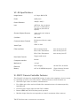
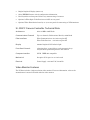
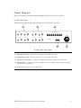
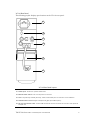
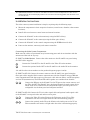
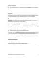
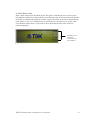
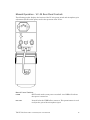
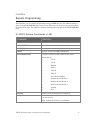
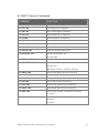
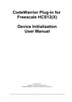
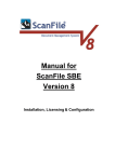
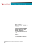
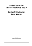
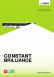
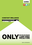
VCS-04 Video Camera System User Manual VCS-04 User Manual Firmware Version 1.3EL Printed in U.S.A. 2000 - 2003 TDK RF Solutions Inc. All rights reserved. The information in this manual may not be reproduced in any form, mechanical or electronic, without express written permission from TDK RF Solutions. Information in this document is subject to change without notice. TDK RF Solutions Inc. 1101 Cypress Creek Road, Cedar Park, Texas 78613 USA Phone: 512/258-9478 Fax: 512/258-0740 www.tdkrfsolutions.com • [email protected] Contents About This User Manual ..............................................................................................................i Safety Precautions...................................................................................................................... ii CHAPTER 1 Introduction .................................................................................................. 1 Purpose and Functions ............................................................................................................. 1 VC-04 Features........................................................................................................................... 1 VC-04 Specifications ................................................................................................................. 2 SI-300CC Camera Controller Features ................................................................................... 2 SI-300CC Camera Controller Technical Data....................................................................... 3 Video Monitor Features ............................................................................................................ 3 CHAPTER 2 Installation .................................................................................................... 4 Before You Begin ....................................................................................................................... 4 Inspection............................................................................................................................. 4 Supplied Components/Accessories................................................................................. 4 Optional Components/Accessories ................................................................................ 4 Product Diagrams...................................................................................................................... 5 SI-300CC Rear Panel........................................................................................................... 5 VC-04 Rear Panel................................................................................................................ 6 Installation Instructions .............................................................................................................. 7 Connecting the Video System Components ................................................................. 7 System Initialization.................................................................................................................... 8 SI-300CC Opening Screen................................................................................................. 8 SI-300CC Menu Screen .................................................................................................... 10 CHAPTER 3 Operating Instructions............................................................................... 11 Getting Started ........................................................................................................................ 11 Remote Operation – SI-300CC Front Panel Controls ......................................................... 11 Menu Page ........................................................................................................................ 12 Options Page..................................................................................................................... 12 GPIB Page .......................................................................................................................... 13 SI-300CC CONFIG Page................................................................................................... 13 Camera Control Module Operation.............................................................................. 14 Manual Operation – VC-04 Rear Panel Controls................................................................ 16 Manual Control Switches................................................................................................. 16 CHAPTER 4 Remote Programming............................................................................... 17 SI-300CC System Commands v1.3EL .................................................................................... 17 SI-300CC Camera Commands ............................................................................................. 18 APPENDIX A Service...................................................................................................... 19 Replaceable Parts................................................................................................................... 19 Service and Ordering Information ........................................................................................ 19 APPENDIX B Maintenance............................................................................................ 20 APPENDIX C Limited Warranty ..................................................................................... 21 About This User Manual The VCS-04 Video Camera System User Manual provides detailed information about the VCS-04 features and operation. This manual is designed to be used as a reference tool for installing and using the VCS-04. Chapter 1 introduces you to the basic features of VCS-04, system components, supported products, and specifications. Chapter 2 provides installation instructions. Chapter 3 covers operation of the VCS-04. Chapter 4 provides commands for remote programming. Note: TDK RF Solutions has made every effort to ensure this manual is both easy to use and factually accurate. If you have any suggestions on improvements you would like to see in this document, or if you discover a discrepancy between the documentation and the VCS-04’s functionality, please notify TDK RF Solutions. TDK RF Solutions Video Camera System User Manual i Safety Precautions Safety Statement The following general safety precautions must be observed during installation, operation, maintenance, and service to the product. Failing to follow these precautions or warnings listed in this manual may result in physical injury. TDK RF Solutions assumes no liability for the user’s failure to follow these precautions. Shock Hazard To minimize shock hazard, the VCS-04 Video Camera System must be connected to an electrical ground. The SI-300CC is equipped with a three-conductor AC power cable. The VC04 is available with either a DC power supply or an AC power supply with a three-conductor AC power cable. The power cable(s) must be plugged into an approved three-contact electrical outlet. Do not attempt to open the product case while power is present. Service Precautions The VCS-04 contains no user serviceable parts. Do not install substitute parts or perform unauthorized modification to this product. Contact a TDK RF Solutions Sales and Support Office for service and repair requirements. To minimize the risk of injury, do not attempt to service, repair, modify, or adjust this product. Safety Messages Warning messages such as the example below may appear in this document. To avoid personal injury and/or damage to the product, warning instructions must be followed. WARNING: No user serviceable parts inside. Contact a TDK RF Solutions Sales and Support Office for service. TDK RF Solutions Video Camera System User Manual ii CHAPTER 1 Introduction Purpose and Functions The VCS-04 is a video camera system designed for use in a shielded room environment for remote monitoring of EUTs (Equipment Under Test) during EMC testing. The system includes: 1. VC-04 shielded color video camera(s) 2. SI-300CC camera controller 3. High resolution monitor VC-04 Features The VC-04 is housed in an EMI hardened protective casing. The main body of the unit contains a camera, lens, and circuitry for remote communication and transmission of the video and audio signals over a fiber link. The remote communication, video and audio signals are done using fiber optics to avoid problems caused by high electromagnetic fields present during EMC testing. The camera can be operated with an AC module or battery module that is mounted on top of the camera. The VC-04 incorporates a 25X optical zoom and offers a 12X digital zoom. The camera also contains a high-speed auto focus lens that adjusts the focus to objects with high luminance and strong contrast in the measurement area. The camera can be controlled remotely via fiber optics or manually via the rear panel. In addition, it also contains an optional microphone for EUT (equipment under test) monitoring, and an optional Pan/Tilt unit for remote positioning. This enables the VC-04 camera to be used in a wide range of applications. Additional features of the VC-04 are: • Glass fiber optic cables are used for communication, video and audio • Use of fiber optic cables allow communications to be uninterrupted by high RF fields • Universal power supply input 100-240 VAC, 50-60Hz or Rechargeable Ni-MH 12V battery • Remote (RS-232) operation of zoom/focus • Optional Pan/Tilt Unit allows for remote movement control TDK RF Solutions Video Camera System User Manual 1 VC-04 Specifications Image Sensor 1/4” Super HAD CCD Pixels 680K pixels Picture Elements 768(H) x 494(V) Lens 25X Zoom, f=2.4 to 60mm, F=1.6 to 2.7, Wide Macro, Auto Focus (Inner Focus System) Shortest Subject Distance 35mm (wide end): 800mm (tele end) S/N Ratio Min. 49dB Communication Channels Bi-directional Serial @ 9600 Baud Video Type NTSC or PAL Fiber Interfaces Fiber Communication 62.5 micron glass ST Fiber Video Transmitter 62.5 micron glass ST Fiber Video Transmitter 62.5 micron glass ST Rear Panel Controls Toggle on/off switch Computer Interface RS-232 Mechanical 3”x3”x6” Electrical Power Supply 100-240 VAC, 50-60 Hz 12V 4A Ni-MH Rechargeable (Typical battery life with full charge, 8 hrs.) Battery SI-300CC Camera Controller Features The SI-300CC is designed to simplify EMC testing. It reduces the complexity of a test system by controlling up to four color video cameras. Additional features of the SI-300CC are: Glass fiber optic cables are used for communication. Use of fiber optic cables and serial links allow communications to be uninterrupted by high RF fields. Universal power supply input 100-240 VAC, 50-60Hz. Remote (IEEE-488) and local (front panel) operation. Modular design allows for easy upgrades (to control a maximum of four cameras). TDK RF Solutions Video Camera System User Manual 2 Bright Graphical Display (240 x 64). Serial EEPROM stores critical configuration information. Dual Joysticks on front panel allows easy maneuvering of cameras. Optional 4 Fiber Optic Video Receivers w/AGC on rear panel. Optional Video Distribution board (1 to 4) on rear panel for connecting to VCRs/monitors. SI-300CC Camera Controller Technical Data Architecture 8051 20 MHz w/20K flash Communication Channels Up to 4 channels, Bi-directional Serial @ 9600 Baud Fiber Interfaces Fiber Communication 62.5 micron glass ST Fiber Video Receiver 62.5 micron glass ST Display 240x64 Graphical LCD w/back-light Front Panel Controls 4 function keys, 4 special keys, and 12 numeric keys 2 Joysticks for positioning devices and cameras Computer Interface GPIB Mechanical Occupies 2U of space in a 19 inch rack Electrical Power Supply 100-240 VAC, 50-60 Hz IEEE-488 compatible Video Monitor Features The VCS-04 includes a high-resolution video monitor. For more information, refer to the manufacturer’s manual included with the video monitor. CHAPTER 2 Installation Before You Begin Before you begin the installation of the VCS-04, conduct an initial inspection of the system and verify that you have received all components with your product. Inspection The VCS-04 was thoroughly tested and inspected prior to shipment. Inspect the product for signs of physical damage that may have occurred during shipping. If damage is discovered, file a claim with the carrier. Supplied Components/Accessories The VCS-04 ships with the following components: VC-04 camera unit SI-300CC camera controller High resolution video monitor Fiber optic cable set BNC video cable AC power cord(s) Manual Verify that you have received the above components. Contact a TDK RF Solutions Sales and Support Office to request additional or replacement components. Optional Components/Accessories The VCS-04 is available with the following optional components: Optional built-in audio and audio cable Optional IEEE-488 serial cable Optional Pan/Tilt unit Optional high resolution flat panel monitor Optional battery and battery charger TDK RF Solutions Video Camera System User Manual 4 Product Diagrams Refer to the following diagrams when installing the VCS-04 video camera system. SI-300CC Rear Panel The following graphic displays port locations on the SI-300CC’s rear panel. S1 Video #1 S2 Video #2 Audio #1 S3 Fiber Optic Channels Audio #2 TX IN OUT Video #3 IN OUT Video #4 IN OUT Audio #3 IN 1 RX TX OUT IN OUT IN OUT RX TX 3 RX Audio #4 IN TX 4 RX POWER OUT WARNING IN 2 IEEE-488 OUT S4 S5 SI-300CC Rear Panel Layout S1 Video Receiver Ports IN and OUT ports (for up to four video receivers). S2 Audio Receiver Ports IN and OUT ports (for up to four audio receivers). S3 Fiber Optic Channel Ports TX (transmit) and RX (receive) ports (for up to four cameras). S4 IEEE-488 Port Port used to connect the SI-300CC to a PC to allow remote control of devices connected to the SI-300CC. S5 Power Input Attach AC power cable here. TDK RF Solutions Video Camera System User Manual 5 VC-04 Rear Panel The following graphic displays port locations on the VC-04’s rear panel. V1 V2 V3 V4 V5 V6 VC-04 Rear Panel Layout V1 Power Input Attach AC power cable here. V2 Manual Power Switch Turns VC-04 power on and off. V3 Ports TX (transmit) and RX (receive), video, and audio ports to connect to the SI-300CC. V4 Potentiometer Control Adjusts microphone gain (for audio option). V5 Pan/Tilt Connection Cable 9-Pin D-SUB connector used to connect the VC-04 to the optional Pan/Tilt unit. TDK RF Solutions Video Camera System User Manual 6 V6 Optional Pan/Tilt Unit Control unit that allows remote or manual adjustments to the VC-04’s horizontal (pan) and vertical (tilt) position. The VC-04 has a mounting plate that will screw onto the Pan/Tilt unit. Installation Instructions The video camera system installation is simple, requiring only the following steps: 1 Mount the components in their respective locations (control room, chamber, other remote locations). 2 Install cable runs between control room and remote locations. 3 Connect the SI-300CC to the video monitor(s) using the BNC cable(s). 4 Connect the SI-300CC to the camera(s) using the fiber optic cable(s). 5 Connect the SI-300CC to the control computer using the IEEE-488 serial cable. 6 Power on the monitor, camera(s), and camera controller. Connecting the Video System Components Make sure the cables are positioned away from moving parts and do not interfere with the movement of the rack in any way. SI-300CC to Video Monitor Connect the video monitor to the SI-300CC rear panel using the BNC cables supplied. S1 S2 Connect the Video OUT on the SI 300CC to the Video IN on the monitor. Connect the optional Audio OUT on the SI-300CC to the Audio IN on the monitor. *S1 and S2 refer to item numbers on the product diagrams (pages 5 and 6). SI-300CC to VC-04 Connect the remote cameras to the SI-300CC rear panel using the fiber-optic cables supplied. Each camera communicates with the SI-300CC using an RS-232 serial communication link that requires a fiber-optic cable with two fibers, one RX (reception) and one TX (transmission). The RX and TX taken together are considered one channel. S3 V3 Connect the RX port on the SI-300CC to the TX port on the remote camera, and the TX to the RX. The SI300CC has a dedicated channel for each remote device, which needs to be connected to the assigned fiber-optic port. The ports are reconfigurable via the front panel and computer interface. SI-300CC to VC-04 Connect the VC-04’s video signal cable and optional audio signal cable to the SI-300CC’s rear panel video and audio receiver ports. S1 V3 Connect the Video IN on the SI-300 to the Video port on the VC-04. This transmitter will emit a red light when the video is functioning properly. S2 V3 Connect the optional Audio IN on the SI-300 to the Audio port on the VC-04. This transmitter will emit a red light when the video is functioning properly. TDK RF Solutions Video Camera System User Manual 7 SI-300CC to Computer S4 Connect the SI-300CC to a control computer using an IEEE-488 cable (not supplied). Power Supply SI-300CC The SI-300CC is equipped with a universal input AC power supply that can operate from a wide range of input AC power allowing it to be used internationally without any jumper settings. The allowable input voltage rating is 100-240 VAC, 50-60Hz. S5 Connect the power cable to an approved grounded outlet. Video Monitor The video monitor is equipped with an AC power supply. Verify that the input connector is compatible with your power supply. Connect the power cable to an approved grounded outlet. If the connector is not compatible with your power supply, add the appropriate adapter and connect to an approved grounded outlet. VC-04 The power module is mounted on top of the VC-04 via a 4-pin LEMO connector. The VC-04 has two options for power – AC and DC. 1. AC Module: Universal input 100-240VAC, 50-60Hz. V1 Connect the power cable to an approved grounded outlet. 2. DC Module: 12V 4A Ni-MH Rechargeable Battery module. The battery module must be removed for recharging. Use only the charger that is supplied with the camera system. These modules are interchangeable. The unit has a RED power LED that will illuminate if the unit is powered on. System Initialization SI-300CC Opening Screen After powering on the remote cameras, you should observe the opening screen shown below with the device name, company name, and IEEE 488 address. TDK RF Solutions Video Camera System User Manual 8 TDK RF Solutions Video Camera System User Manual 9 SI-300CC Menu Screen After a brief setup period, the Menu Screen will appear, allowing the user to select one of four different cameras by using the F1-F4 keys. Enter the page of interest and verify that the SI-300CC is communicating with the remote camera. The status of the device should change from “[N/A]” to “[A]” once communication is established. If it remains in the “[N/A]” mode, check that the remote device is powered on, then check that the fiber-optic cables are connected properly. Displays up to 4 cameras connected to the SI 300CC TDK RF Solutions Video Camera System User Manual 10 CHAPTER 3 Operating Instructions Getting Started The VC-04 color video camera can be operated remotely via fiber optic links to the SI-300CC camera. This chapter covers both remote and manual operation. Remote Operation – SI-300CC Front Panel Controls The front panel of the SI-300CC is designed to be user-friendly yet flexible enough to accommodate the wide variety of functions that the unit is used for. TDK RF Solutions MEN U F1 POWER ON 8 F2 4 5 6 N EXT 1 2 3 EN TER 0 + /- . F4 2 3 4 CW/ CCW ZO O M 9 F3 OFF 1 7 CLR 5 U P / D N F O C U S X/ 0 PA N T Y I / L O T 6 1 Power Switch – used to power the SI-300CC on and off. 2 LCD – 240 x 64 backlit liquid crystal display (LCD). 3 Function Keys (F1-F4) – general purpose keys for different uses, depending on the screen selected. These function keys are called “soft keys” since their function can be reconfigured by software. The screen will display a keyword (e.g. “STOP”, “ZERO”, etc.) next to each key depending on its current function. Some keys may be unused at a given time. Press the respective function key to perform the task described by the keyword. 4 Special Keys - four dedicated keys that are used for various functions on the SI-300CC. The “MENU” key can be pressed at any time to return to the Main Menu. The “CLEAR” key can be used to clear data that has been entered on the screen. The “NEXT” key can be used to scroll through the different pages. The “ENTER” key can be used to process data from the numeric keypad. 5 Numeric Keypad section for data entry. This includes numbers “0” through “9”, a “+/-“ key, and a “.” key. A blinking cursor or a highlighted number indicates the current field that will be modified. Once the value has been entered, press “ENTER” for the value to take effect. Depending on the screen some numbers may be unused. 6 Joysticks (two) - used to control camera position. The joysticks are labeled for various tasks depending on the module that they are controlling. They are labeled for their appropriate function as follows: TDK RF Solutions Video Camera System User Manual 11 CW/CCW: This is used for turntables to turn the table clockwise or counterclockwise ZOOM: This is used for cameras to zoom in and out UP/DOWN: This is used for masts to make the mast go up and down X/θ: This is used for x-y positioners and the manipulators PAN: This is used for cameras to pan left and right Y/φ: This is used for x-y positioners and manipulators TILT: This is used for cameras to tilt up and down The following sections describe in detail how each different page is operated. Menu Page Press F1 to control this camera Press F2 to control this camera Press F3 to control this camera Press F4 to control this camera The main menu can always be reached by pressing the “MENU” key. This screen allows the user to easily maneuver through the different SI-300CC modules. The SI-300CC can be configured with as many as 4 different modules. These modules will be displayed on the right hand side of the screen. The module page can be accessed by pressing the corresponding “F” key. While in the menu page the “NEXT” key can be pressed to access the SI-300CC options page. Options Page Go to Main Menu Go to GPIB Page Go to Configuration Page The options menu can always be reached by pressing the “NEXT” key while in the main menu page. This screen allows the user to easily maneuver through the different SI-300CC options. The abbreviations and functions present on the menu screen are: TDK RF Solutions Video Camera System User Manual 12 MODULE SELECT: (F1) Module Select: Pressing this key will take the user to the main menu screen where the user can choose one of four modules to operate. GPIB ADDRESS: (F2) GPIB Address: Pressing this key will take the user to the GPIB page. This page can be used to check or change the GPIB address. The SI-300CC retains the GPIB address in a serial EEPROM. SI-300CC CONFIG: (F3) SI-300CC Configuration: Pressing this key will take the user to the configuration page. This page allows the user to change or configure the module on each channel (up to 4 channels). Note: The module configurations are preset at the factory and the user should take special care when using the configuration features of the SI-300. GPIB Page Enter a GPIB address Return to Main Menu This screen allows the user to check or change the GPIB address. Simply type in a number from 0 to 30 and then hit the “ENTER” key, and the new address will take effect. The address is stored in a serial EEPROM. The “EXIT” key can be pressed at any time to return to the main menu. SI-300CC CONFIG Page Scroll through available channels Configure the module that is currently highlighted Return to Main Menu This screen allows the user to change or configure each module on the SI-300CC. The abbreviations and functions present on the configure screen are: NEXT CHANNEL: (F1) Next Channel: Pressing this key scrolls the user through the four available fiber optic serial channels on the SI-300CC. Once the proper channel is highlighted then the user can change or configure the module on this channel. TDK RF Solutions Video Camera System User Manual 13 CONFIG: (F2) Configure: Pressing this key allows the user to enter the configuration for the module that is currently highlighted. Not every module has a configuration screen. EXIT: (F4) Exit: This key takes the user back to the Main Menu Camera Control Module Operation Enter the Camera Control Module page by pressing the appropriate F-key from the Module page. There are two different camera pages available depending on the configuration of the SI-300. Once a camera page is displayed, the joysticks can be used for the PAN, TILT, ZOOM and FOCUS functions. This page only displays the name of the camera and the channel number it is on. VC-04 PAGE Toggle auto focus on or off Toggle zoon on or off Set memory position Recall a saved memory position This page gives the user the ability to turn the Auto Focus on and off and to save and recall camera positions. The following is a description of the different functions present on this page: Auto Focus ON/OFF: (F1) Auto Focus ON or OFF. This key can be toggled to send a command to the camera to turn the auto focus on or off. Set: (F3) Set memory position. When a number is entered in the Position field, pressing this key will save the current zoom, focus, pan and tilt positions. Recall: (F4) Recall memory position. When a number is entered in the Position field, pressing this key will recall the corresponding saved memory positions for that number. CONFIGURATION PAGE Enter the VC-04 camera configuration page by first going to the options page and pressing the “F3” key to go to the SI-300CC configuration page. The user can scroll through each channel using the “F1”(NEXT CHANNEL) key. Once the proper camera is highlighted the “F2”(CONFIG) key can be pressed to enter the VC-04 camera configuration page. This page gives the user the ability to set and display the identification tag and adjust the iris TDK RF Solutions Video Camera System User Manual 14 IRIS ADJUST: The joystick labeled UP/DN can be used to adjust the iris up and down. There are a total of 17 steps of adjustment in the camera. Each time the joystick is toggled up or down the iris will adjust one step. The following is a description of the different functions present on this page: ID ON/OFF: (F1) ID ON or OFF. This key can be toggled to send a c command to the camera to turn the identification tag on or off. IRIS RESET: (F2) RESET Iris position. Pressing this key will reset the iris position to the factory default. PREV: (F3) Previous: Pressing this key will take the user back to the SI-300CC configuration page. EXIT: (F4) Exit: This key takes the user back to the Main Menu TDK RF Solutions Video Camera System User Manual 15 Manual Operation – VC-04 Rear Panel Controls The following graphic displays the location of the VC-04’s power switch and microphone gain adjustment (for the audio option) used in the operation of the VC-04. Manual Control Switches POWER SPDT switch used to turn power on and off. A red LED will indicate that power is turned on. MIC GAIN: Located below the VIDEO fiber connector. This potentiometer is used to adjust the gain of the microphone signal. TDK RF Solutions Video Camera System User Manual 16 CHAPTER 4 Remote Programming The SI-300CC can be remotely programmed using an IEEE-488 bus. The address setting is done on the GPIB ADDRESS page of the SI-300. This page can be selected by pressing F2 in the Main Menu page. The address is displayed during power up and on the GPIB ADDRESS page. SI-300CC System Commands v1.3EL COMMAND FUNCTION *RST RESETS SI300 SI:MODULE Returns to the Main Menu (Module) Page SI:MENU Returns to the Options Page *IDN? Returns “SI-300 SYSTEM INTERFACE” SI:CONFIGX:CHZ Configure Channel Z with module X (hex value) Module #(hex) 0 VC-03 1 VC-04 2 FP4000 3 FP600 4 PP02-X 5 PP02-Y 6 Local Switch Module 7 Remote Switch Module 1 8 Remote Switch Module 2 9 Remote Switch Module 3 A B Preamp N/A SI:CHZ Changes to the module page on channel Z SI:Q:CHZ Returns module number on channel Z in hex format: 0 to 9 then A to B “M=2” module on channel x is an FP4000 TDK RF Solutions Video Camera System User Manual 17 SI-300CC Camera Commands COMMAND FUNCTION CA:TD:CHZ Tilt camera Down on channel Z CA:TU:CHZ Tilt camera Up on channel Z CA:PR:CHZ Pan camera Right on channel Z CA:PL:CHZ Pan camera Left on channel Z CA:ZI:CHZ Zoom camera In on channel Z CA:ZO:CHZ Zoom camera Out on channel Z CA:ST:CHZ Stops Pan/Tilt and Zoom/Focus on channel Z CA:IDON:CHZ Turn the Identification tag on CA:IDOFF:CHZ Turn the Identification tag off CA:IDSETXY:CHZ Set the Identification tag 00<=XY<=99 CA:IRISRESET:CHZ Reset the Iris Position to the factory default setting CA:IRISSETXY:CHZ Set the Iris Position. 00<=XY<=11 EX: XY=03 or XY=11 or XY=08 or XY=00 CA:DZON:CHZ Turn On the Digital Zoom on channel Z CA:DZOFF:CHZ Turn Off the Digital Zoom on channel Z CA:FI:CHZ Focus camera In on channel Z CA:FO:CHZ Focus camera Out on channel Z CA:AON:CHZ Turn On the Auto Focus on channel Z CA:AOFF:CHZ Turn Off the Auto Focus on channel Z CA:MSX:CHZ Save camera position to memory on channel Z 1<=X<=6 CA:MRX:CHZ Recall saved camera position from memory on channel Z 1<=X<=6 TDK RF Solutions Video Camera System User Manual 18 APPENDIX A Service Replaceable Parts The VCS-04 contains no user replaceable parts. For service, contact a TDK RF Solutions Sales and Support Office. Service and Ordering Information To request service, to place an order, or to learn more about the TDK RF Solutions products that best meet your needs, contact your TDK representative: TDK RF Solutions Inc. 1101 Cypress Creek Rd. Cedar Park, Texas 78613 USA Phone: 512-258-9478 Fax: 512-258-0740 E-mail: [email protected] World Wide Web: www.tdkrfsolutions.com TDK Electronics Europe GmbH. Wanheimer Str. 57 40472 Düsseldorf, Germany Phone: +49/211-9077-0 Fax: +49/211-4149843 TDK RF Solutions Video Camera System User Manual 19 APPENDIX B Maintenance The design of the VCS-04 is such that little or no maintenance is required under normal usage. To ensure years of uninterrupted service from VCS-04, perform the following procedures: 1 Inspect the VCS-04 on a regular basis to make sure that the unit is clean and functioning properly, and all cables and connectors are securely fastened and in good condition. 2 Tighten the screws that mount the SI-300CC to the rack and the VC-04 to its stand. Normal us may cause equipment screws to loosen over time. 3 Verify that the product has not been damaged in any way. If damage has occurred, it should be repaired properly. Call your TDK RF Solutions representative to request service. Physical damage to the product should be repaired prior to placing it in service. Perform the recommended maintenance every three months. This time may be varied depending on the frequency of use TDK RF Solutions Video Camera System User Manual 20 APPENDIX C Limited Warranty TDK RF Solutions Inc. warrants to the end-user customer that this product, exclusive of software (referred to herein as “Hardware” or “Product”) will be free from defects in material and workmanship for a period of one (1) year from date of shipment. If TDK RF Solutions receives notice of any such defects during the warranty period, TDK RF Solutions will, at its option, either repair or replace the Product which it finds to be defective at no charge (except for shipping and insurance). Repair of defective Product may be with either new or rebuilt replacement parts that will be warranted for the remainder of the original warranty period. Any exchanged parts under this warranty will become the property of TDK RF Solutions. Replacement Product may be either new or reconditioned. If the Product is discontinued and no longer available, then it may be replaced with Product determined by TDK RF Solutions to be of similar value and performance. TDK RF Solutions warrants to the end-user customer that the TDK RF Solutions-branded software included with the Product (herein referred to as "EA Software") when properly installed and used will materially operate in material conformance with the specifications found in the user documentation, for a period of ninety (90) days from the date of purchase. If TDK RF Solutions receives notice of any defects in materials or workmanship in the EA Software media during the warranty period, TDK RF Solutions will replace the EA Software media which it finds to be defective at no charge (except for shipping and insurance). Any software other than EA Software included with the Product is supplied on an “AS IS” basis and without any representations or warranties of any kind, whether express or implied, including but not limited to the implied warranties of merchantability, fitness for a particular purpose, title and non-infringement. Please refer to any documentation included with such software for your rights and obligations with respect to that software. TDK RF Solutions does not warrant that the operation of the Product will be uninterrupted or error free. This Limited Warranty does not apply to defects resulting from (1) acts of God, accident, misuse, abuse, negligence, abnormal, or unusually heavy use; (2) improper installation, operation, testing or maintenance; (3) power failure or connection to improper voltage supply; or (4) modification or attempted repair by any party other than TDK RF Solutions. This Limited Warranty does not apply to normal wear and tear, consumable items, calibration of the product, if applicable, or when the malfunction results from the use of the Product in conjunction with other products, software or accessories, or where it is determined by TDK RF Solutions that there is no fault with the Product itself. This Limited Warranty is invalid if the factory-applied serial number has been altered or removed from the Product. This Limited Warranty extends only to the original end-user customer and is not transferable to any subsequent purchaser. This Limited Warranty is void if items are shipped outside the USA without prior knowledge of TDK RF Solutions. A return authorization is required for repairs under warranty. In order to obtain warranty service, you must deliver the Product to TDK RF Solutions freight prepaid, in either its original package or packaging providing a degree of protection equivalent to that of the original packaging, along with proof of purchase. [Please contact TDK RF Solutions at the number listed below for further information.] TDK RF Solutions Video Camera System User Manual 21 TDK RF SOLUTIONS INC. MAKES NO OTHER WARRANTIES, EXPRESS OR IMPLIED, INCLUDING BUT NOT LIMITED TO THE WARRANTIES OF MERCHANTABILITY OR FITNESS FOR A PARTICULAR PURPOSE. TO THE EXTENT THAT ANY IMPLIED WARRANTIES APPLY, DESPITE THEIR EXCLUSION UNDER THIS LIMITED WARRANTY, SUCH WARRANTIES SHALL BE LIMITED TO THE DURATION OF THE EXPRESS WARRANTIES PROVIDED HEREUNDER. THE REMEDIES PROVIDED UNDER THIS LIMITED WARRANTY ARE THE SOLE AND EXCLUSIVE REMEDIES. TDK RF SOLUTIONS’ LIABILITY UNDER ANY LEGAL THEORY FOR ANY LOSS OR DAMAGE IN ANY WAY RELATED TO THE PRODUCT SHALL IN NO EVENT EXCEED THE PURCHASE PRICE OF THE PRODUCT. IN NO EVENT SHALL TDK RF SOLUTIONS INC. BE LIABLE FOR ANY INCIDENTAL OR CONSEQUENTIAL DAMAGES RESULTING FROM THE USE OF THE PRODUCT. Some states do not allow limitations on how long an implied warranty lasts or any exclusion or limitation of incidental or consequential damages, so the above limitations or exclusions may not apply to you. This warranty gives you specific legal rights, and you may have other rights which vary from state to state. TDK RF Solutions Inc. – A TDK Group Company 1101 Cypress Creek Rd. Cedar Park, Texas 78613 USA Phone: 512-258-9478 Fax: 512-258-0740 TDK RF Solutions Video Camera System User Manual 22 Index A Architecture, 3 Audio Receiver Ports, 5 Auto Focus ON/OFF, 13 C Camera Commands, 17 Camera Control Module Operation, 13 CONFIGURATION PAGE, 13 VC-04 PAGE, 13 Communication Channels, 3 Components, 4 CONFIG, 12, 13 CONFIGURATION PAGE, 13 Connecting Components, 7 CW/CCW, 10 D damage, ii, 4, 19 E Electrical, 3 EXIT, 12, 13, 14 F Features – VC04, 1 Features –SI300, 2 Fiber Interfaces, 3 Fiber Optic Channel Ports, 5 Front Panel, 3, 10 Function Keys, 10 G GPIB ADDRESS, 12, 16 GPIB Page, 12 I ID ON/OFF, 14 IEEE-488, 2, 3, 5, 16 Installation, 4, 7 IRIS RESET, 14 TDK RF Solutions Video Camera System User Manual J joysticks, 10, 13 M Maintenance, 19 Manual Control, 6 MENU, 10 Menu Page, 11 Menu Screen, 9 MODULE SELECT, 11 N NEXT CHANNEL, 12, 13 Numeric Keypad, 10 O Opening Screen, 8 Operating Instructions, 10 Options, 4 Options Page, 11, 16 P PAN, 11, 13 port, 5, 6, 7 Ports, 6 Potentiometer, 6 Power Supply, 8 PREV, 14 Product Diagrams, 5 Purpose and Functions, 1 R Rear Panel – SI-300CC, 5 Rear Panel – VC-04, 6 Rear Panels Controls - VC-04, 15 Recall, 13, 17 Remote Programming, 16 Camera Commands, 17 System Commands, 16 S Safety Messages, ii 23 Safety Precautions, ii Safety Statement, ii Serial EEPROM, 2 Service, 18 Replaceable Parts, 18 Service and Ordering Information, 18 Service Precautions, ii Set, 13, 17 Shock Hazard, ii special keys, 3, 10 MENU, 10 STOP, 10 System Commands, 16 T TILT, 11, 13 U UP/DOWN, 11 TDK RF Solutions Video Camera System User Manual V VC-04 PAGE, 13 Video Receiver Ports, 5 W warning, ii Warranty, 20 X X/θ, 11 Y Y/φ, 11 Z ZERO, 10 ZOOM, 11, 13 24