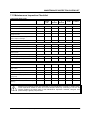
1
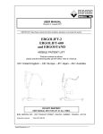
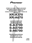
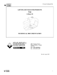
USER MANUAL
Revision 4, Jan 2002
IMPORTANT: Read these instructions before installing, operating, or servicing this system
Series 420, 550 and 800
1.1.1 DO NOT DESTROY
KEEP KEY ENCLOSED AND MANUAL WITH
THE LIFT AT ALL TIMES.
Instruction manual
Part # 001.08860
VOYAGER 420/550/800 (rev. 3A)
1
INTRODUCTION
This lift has been distributed by Joerns Healthcare Ltd.
It is manufactured by BHM Medical Inc, Quebec, Canada.
Please take the time to read the entire manual, including the section on Safety Instructions and Warnings.
It contains important information that will allow you to take advantage of all the characteristics of your
Voyager patient lift.
Suitability
The Voyager range of lifts are suitable for the following categories of lift within the working parameters of
the lifts specified in the technical specifications:Category A – Wheelchair
Category B – Bed
Category C – Bath
Category D – Toilet/ shower chair
Category E – Floor
Category F – 90 degree rotation
The Voyager series are suitable for patients in the sitting, sitting/recumbent and recumbent positions.
Approvals
CSA 601.1
UL 2601.1
EN 60601.1
EN ISO 10535 (Lifting device) SGS
UK Test Report: DUR22107/AC/OO
Note:
BHM Medical is constantly improving its products. For this reason, it may be possible to
encounter a modification of product without revision of this guide.
Joerns Healthcare Ltd
High St, Wollaston
Stourbridge
W.Midlands
DY8 4PS
Tel +44 1384 446688
Fax +44 1384 446699
wwwjoerns.co.uk
VOYAGER 420/550/800 (rev. 3A)
BHM Medical Inc.
2001 Tanguay Street
Magog (Quebec)
Canada J1X 5Y5
Phone: +1 (819) 868-044
Fax +1(819) 868-2249
www.bhm-medical.com
email: [email protected]
2
TABLE OF CONTENTS
INTRODUCTION.................................................................................................................................................. 2
Suitability........................................................................................................................................................... 2
Approvals.......................................................................................................................................................... 2
1
INTRODUCTION ........................................................................................................................................ 5
1.1
How to use this Manual..................................................................................................................... 5
1.2
Equipment Identification .................................................................................................................... 5
1.3
Receipt of Equipment ........................................................................................................................ 5
1.4
Key to Symbols .................................................................................................................................. 5
2
SAFETY INSTRUCTIONS AND WARNINGS.......................................................................................... 6
2.1
GENERAL .......................................................................................................................................... 6
2.2
LIFTING WITH THE VOYAGER....................................................................................................... 7
2.3
SLING USAGE................................................................................................................................... 7
2.4
ELECTRICAL WARNING - SHOCK PREVENTION ....................................................................... 7
2.5
ELECTRICAL WARNING - INSTALLATION AND GROUNDING.................................................. 8
2.6
ELECTRICAL WARNING - SERVICE AND MAINTENANCE........................................................ 8
2.7
FIRE AND EXPLOSION PREVENTION .......................................................................................... 8
2.8
PARTS AND ACCESSORIES .......................................................................................................... 8
2.9
EQUIPMENT WARNING LABELS ................................................................................................... 8
3
DESCRIPTION VOYAGER 420 ................................................................................................................ 9
3.1
Lift Unit................................................................................................................................................ 9
3.2
Parts Description................................................................................................................................ 9
3.3
What's included.................................................................................................................................. 9
3.4
Dimensions......................................................................................................................................... 9
4
DESCRIPTION VOYAGER 550 .............................................................................................................. 10
4.1
Lift Unit.............................................................................................................................................. 10
4.2
Parts Description.............................................................................................................................. 10
4.3
What's included................................................................................................................................ 10
4.4
Parts Description.............................................................................................................................. 10
4.5
Dimensions....................................................................................................................................... 10
5
DESCRIPTION VOYAGER 800 ............................................................................................................. 11
5.1
Lift Unit.............................................................................................................................................. 11
5.2
Parts Description.............................................................................................................................. 11
......................................................................................................................................................................... 11
5.3
What’s Included with the Voyager 800........................................................................................... 11
5.4
Dimensions....................................................................................................................................... 11
6
Operation.................................................................................................................................................. 12
6.1
How to use the Voyager 420, Voyager 550 and Voyager 800 ..................................................... 12
6.2
Sling Usage ...................................................................................................................................... 13
6.3
Emergency Stop (Red cord) ........................................................................................................ 13
6.4
6.5
6.6
6.7
6.8
6.9
Emergency Lowering Feature......................................................................................................... 13
Emergency Brake ............................................................................................................................ 14
Frame with mechanical clips........................................................................................................... 14
Battery Information .......................................................................................................................... 14
Charging the battery ........................................................................................................................ 14
Charger Specification: ..................................................................................................................... 15
VOYAGER 420 - 550 – 800 (rev. 3A)
3
User Manual Voyager 420-55-800
7
MAINTENANCE ....................................................................................................................................... 16
7.1
Daily Check List ............................................................................................................................... 16
7.2
Inspection and Cleaning.................................................................................................................. 16
7.3
Strap Inspection ............................................................................................................................... 16
7.4
Handling and Storage...................................................................................................................... 17
7.5
Battery Replacement....................................................................................................................... 17
7.6
Charger Fuse Replacement............................................................................................................ 17
7.7
.Charger Fuse Replacement (for UK only) .................................................................................... 18
7.8
Sling Inspection................................................................................................................................ 18
7.9
Annual Inspection ............................................................................................................................ 18
7.10
UK Regulations ................................................................................................................................ 18
7.11
Maintenance Inspection Checklist.................................................................................................. 19
8
TROUBLESHOOTING............................................................................................................................. 20
9
ACCESSORIES........................................................................................................................................ 22
10
LOG BOOK............................................................................................................................................... 23
11
WARRANTY ............................................................................................................................................. 26
VOYAGER 420/550/800 (rev. 3A)
4
INTRODUCTION
1
INTRODUCTION
1.1 How to use this Manual
DO NOT ATTEMPT TO USE THIS
EQUIPMENT WITHOUT UNDERSTANDING THIS MANUAL.
To ensure safe operation, read the entire
manual carefully, especially the section on
“Safety Instructions and Warnings”, before
installing, operating, or servicing this
equipment.
If anything is not completely understood,
please contact your supplier for more
details. Failure to comply with warnings in
this manual may result in injury.
Keep this manual with the lift and refer to it
as required. Contents of this manual are
subject to change without prior notice to
users.
Throughout this manual, the following symbols
may appear. Pay particular attention to the
information provided under these headings.
These special annotations are easily recognized
as follows:
WARNING:
intended to
hazards or
which could
bodily harm.
1.2 Equipment Identification
The unit's identification number (specification,
model, serial number) appears on a silver
nameplate attached to the back of base.
1.3 Receipt of Equipment
Upon receipt of the equipment, verify it against
the packing list to ensure it is complete and
inspect the equipment for possible damage due
to shipping. If there is any damage, DO NOT
USE the equipment and notify the carrier
immediately to file a claim. Provide complete
information concerning damage claims or
shipping errors to your supplier. Include all
equipment identification numbers and group part
numbers (if any) as described above along with
a full description of damaged parts.
1.4 Key to Symbols
The following symbols are used on lifter’s
attachment labels:
This symbol is required to be displayed
on regulated products for sale in the
European Market. It indicates that the
product
complies
with
applicable
European Directives related to health,
safety, environment and consumer
protection.
this
symbol
is
alert the user to
unsafe practices,
result in serious
SWL
CAUTION: this symbol is intended
to alert the user of the presence of
important
operating
and
maintenance instructions, which
could prevent product damage or
possible personal injury.
Safe Working Load represents the
maximum load the lifter is rated for safe
operation.
The following symbols are used on sling labels
and related to washing instructions:
71ºC
Maximum washing temperature 71°C
(140°F) permanent cycle.
Do not use bleach.
NOTE: this symbol offers helpful
information concerning certain
operating procedures.
Additional copies of this manual can be
purchased by contacting your supplier. Include
the User Manual product number and equipment
identification numbers.
VOYAGER 420 - 550 – 800 (rev. 3A)
Do not dry clean.
Tumble dry low temperature.
Do not iron.
Please refer to individual sling labels for
complete instructions regarding washing and
drying.
5
SAFETY INSTRUCTIONS & WARNINGS
2
SAFETY INSTRUCTIONS AND WARNINGS
IMPORTANT – READ AND UNDERSTAND THESE INSTRUCTIONS. DO NOT LOSE THEM. ALSO
READ OPERATING/ INSTRUCTION CHAPTER OF THIS MANUAL BEFORE INSTALLING,
OPERATING OR SERVICING THIS EQUIPMENT
2.1 GENERAL
Ø IMPORTANT – READ THESE INSTRUCTIONS CAREFULLY OR SERIOUS INJURY MAY RESULT.
Ø KEEP THESE INSTRUCTIONS AND THE KEY PROVIDED WITH THE LIFT AT ALL TIMES.
Ø READ OPERATION AND MAINTENANCE INSTRUCTIONS IN THIS MANUAL BEFORE
INSTALLING, OPERATING, OR SERVICING THIS EQUIPMENT.
Ø An authorized contractor or installer must install Voyager ceiling lifts.
Ø
USE all controls and safety features only according to the rules specified in this manual.
Never attempt to force a control or button on the lift.
Ø
DO NOT store the charger in a shower, bath or other areas with high humidity.
Ø
DO NOT drop the patient lift or battery. Dropping the battery or lift may cause internal damage
that is not easily seen. If lift is suspected to be damaged, take to an authorized technician for
servicing.
Ø
IMPORTANT: Keep all components of the lift clean and dry, and have electrical and mechanical
safety checkpoints done as instructed in the Maintenance section of this manual.
Ø
Replace any precautionary or instruction labels that cannot be easily read.
Ø Avoid violent shock during transportation.
VOYAGER 420 - 550 – 800 (rev. 3A)
6
User Manual Voyager 420-55-800
2.2 LIFTING WITH THE VOYAGER
Ø
YOUR LIFT is for transferring patients only. Do not use the lift for any other purpose.
Ø
ALWAYS carry out the daily checklist before using the lift.
Ø
Voyager ceiling lifts are intended to be used for patients within the specified weight limit
indicated for the lift. Do not attempt to lift more than the weight limit indicated.
Ø
Before attempting to transfer, the patient must be assessed by a qualified professional.
Ø
Voyager ceiling lifts must be used by a caregiver with proper training to work with the patient
to be transferred.
Ø
ONLY trained and qualified caregivers should transfer a patient. DO NOT attempt to use the lift
if you have not been properly trained to do so.
Ø ALWAYS be prepared before attempting to transfer a patient.
Ø FOLLOW lifting procedures outlined in this manual.
2.3 SLING USAGE
Ø ONLY use Oxford/Hoyer slings that are designed to fit with the Voyager
Ø ALWAYS refer to the Sling User Manual for instruction on fitting, care and maintenance
Ø
DO NOT use a sling that is not recommended for the lift.
Ø
NEVER use a damaged, torn or frayed sling.
Ø
ALWAYS place the sling around the patient according to the instructions enclosed.
Ø
Voyager ceiling lifts are specifically designed for Oxford Voyager ceiling rail systems, slings
and accessories. Slings and accessories designed by any other manufacturer are prohibited
and will void the Voyager warranty. Use only Oxford/Hoyer slings and accessories to
maintain patient safety and product utility.
Ø
DO NOT use other manufacturer’s slings.
Ø DO NOT use Oxford/Hoyer slings on other manufacturer’s hoists.
2.4 ELECTRICAL WARNING - SHOCK PREVENTION
Ø DO NOT touch or use a lift with bare conductors or a damaged power cord. Electrically live
equipment can electrocute a patient. If the lift or charger has any exposed or damaged wires
contact your local dealer immediately.
Ø DO NOT cut or remove the round grounding prong from any plug. All Voyager lifts are
equipped with three-prong plugs to protect from shock hazard or electrocution. Any twoprong electrical outlet must be replaced with a properly grounded three-prong outlet according
to the National Electrical Code and local codes. It is the responsibility of the customer to have
the work done by a qualified electrician.
Ø DO NOT splash or expose electric parts of the device to water or moisture.
Ø CHECK nameplate for voltage and cycle requirements. These requirements differ by country.
Do not attempt to use the lift in an area that has a different voltage and cycle requirement.
Ø DO NOT attempt to expose, service or repair the lift, battery or charger.
malfunctioning, contact your local dealer.
If any unit is
Ø READ the battery and charger instructions thoroughly before using or storing them.
VOYAGER 420/550/800 (rev. 3A)
7
User Manual Voyager 420-55-800
2.5 ELECTRICAL WARNING - INSTALLATION AND GROUNDING
Ø Electrical equipment must be installed and maintained in accordance with National Electrical
Codes.
Ø Check nameplate for voltage and cycle requirements.
Ø In special locations i.e. bathrooms, showers or swimming pools a supplementary earth bond
must be connected at the mains supply socket. Where the Voyager Lift is supplied by a short
length of flex from an adjacent power point, the green yellow connection within the flex may be
deemed to constitute supplementary bonding. In some regions Local Authorities may specify
an additional supplementary earth to the track. This can be taken from any earth terminal on
the charger end stop.
Ø Refer to a qualified electrician who knows the latest regulations in the installation of this
equipment.
2.6 ELECTRICAL WARNING - SERVICE AND MAINTENANCE
Ø Disconnect power cord from the charger rail stopper or switch of transformer at power supply,
and unplug the battery from the lift before inspecting, adjusting or servicing the equipment.
Disconnect power to equipment if it is to be left unattended or out of service.
2.7 FIRE AND EXPLOSION PREVENTION
Ø Batteries may explode, leak and cause personal injury if not disposed of properly.
•
Do not place or store the battery under direct sunlight or near a heat source
•
Do not dispose of in fire
•
Do not short the battery terminals
•
Do not incinerate
•
Flush with water if electrolyte (Acid) comes in contact with skin or eyes.
Ø Batteries must be recycled, disposed of according to local law regulations. When returning
batteries, insulate their terminals with adhesive tape, etc. Otherwise, the residual electricity in
used batteries may cause fire or explosion.
2.8 PARTS AND ACCESSORIES
Ø Always use VOYAGER replacement parts and accessories. Using other parts and accessories
other than recommended by BHM/ JOERNS could affect security and efficiency of the entire
system. OXFORD VOYAGER slings and patient lift accessories are specifically designed to be
used in conjunction with BHM patient transfer aids. Sling and accessories designed by other
manufactures are not to be used as a component of VOYAGER patient transfer systems.
2.9 EQUIPMENT WARNING LABELS
Ø INSPECT all precautionary labels on the equipment. Order and replace all labels that cannot be
easily read.
VOYAGER 420/550/800 (rev. 3A)
8
User Manual Voyager 420-55-800
3
DESCRIPTION VOYAGER 420
3.3 What's included
3.1 Lift Unit
OPERATING FEATURES
• Lifting capacity: 190 kg (420 lbs.)
• Average weight: 12.7 kg (28 lbs.) battery incl.
• Electronic soft-start and soft-stop motor.
• Manual &electric emergency lowering device.
• Emergency brake (for mechanical failure)
• Emergency stopping device.
• Current limiter for circuit protection.
• Low battery disconnect system to protect
batteries from being drained.
• Lifting speed: 4 cm/sec. (1.6 in./sec.).
• Horizontal displacement speed: 20 cm/sec
• Vertical & horizontal motor: 24 VDC, 1/12 HP
• Strap length up to 2.2 m.
• ISO 10535.
ITEM
QTY
Voyager 420 lift
1
Battery (inside unit)
Integrated Charger Stopper (hardwired
for UK only)
Rail Stopper
1
Handset
1
Carry bar
1
Power cord
1
4mm Allen key
1
Instruction manual
1
1
1
3.2 Parts Description
3.4 Dimensions
Trolley
Control
switches
Rail
Handset
Allen key
2-function
Charging light
4-funtion
Emergency stop
Low-battery
indicator
Emergency
lowering
Rail stopper
Integrated
charger stopper
Carry bar
Fuse magazine
Power cord
Charger
Stopper for UK
only
VOYAGER 420/550/800 (rev. 3A)
9
BHM SLING
4
DESCRIPTION VOYAGER 550
4.5 Dimensions
4.1 Lift Unit
OPERATING FEATURES
• Lifting capacity: 250 kg (550 lbs.)
• Av. weight: 22.73kg (50 lbs.) battery included
• Electronic soft-start and soft-stop motor.
• Manual and electric emergency lowering.
• Emergency brake.
• Emergency stopping device.
• Current limit for circuit protection.
• Low battery disconnect system to protect
batteries from being drained.
• Lifting speed: 6 cm/sec. (2.4 in./sec.)
• Horizontal displacement speed: 15 cm/sec. (6
in/sec.) and 25 cm/sec. (9.8 in./sec.)
• Vertical axis motor: 24 VDC, 1/8 HP.
• Horizontal axis motor: 24 VDC, 1/10 HP
• Strap length up 3.6 m (144 inches).
4.2 Parts Description
•
As per Voyager 420 (previous page)
4.3 What's included
ITEM
QTY
Voyager 550 lift
1
Battery (inside unit)
1
Integrated Charger Stopper
1
Rail Stopper
1
Handset
1
Carry bar
1
Power cord
1
Instruction manual
1
4 mm Allen Key
1
4.4 Parts Description
•
As per Voyager 420 (see previous page)
VOYAGER 420/550/800 (rev. 3A)
10
BHM SLING
5
DESCRIPTION VOYAGER 800
5.3 What’s Included with the
Voyager 800
5.1 Lift Unit
OPERATING FEATURES
• Weight capacity: 360 kg (800 lbs.)
• Average weight: 22.73 kg (50 lbs.) battery incl
• Electronic soft-start and soft-stop motor.
• Manual and electric emergency lowering.
• Emergency brake.
• Emergency stopping device.
• Current limit for circuit protection.
• Low battery disconnect system to protect
batteries from being drained.
• Lifting speed: 3 cm/sec. (1.2 in./sec.)
• Horizontal displacement speed : 15 cm/sec
• Vertical axis motor: 24 VDC, 1/8 HP
• Horizontal axis motor: 24 VDC, 1/10HP.
• Strap length up to 1.3 m. (49.5 inches).
ITEM
QTY
Voyager 800 lift
1
Battery (inside unit)
Integrated Charger Stopper (Harwired
version for UK market only)
Rail Stopper
1
Handset
1
Carry bar 450 kg (1000 lbs.)
1
Power cord
1
4 mm Allen key
1
Instruction manual
1
1
1
5.2 Parts Description
Control
switches
Handset
5.4 Dimensions
Trolley
Rail
4-function
Low-battery
indicator
Charging light
Emergency
lowering
Emergency stop
Carry bar
Integrated
charger stopper
Rail stopper
Fuse magazine
Power cord
VOYAGER 420/550/800 (rev. 3A)
11
OPERATION
6
OPERATION
6.1 How to use the Voyager
420, Voyager 550 and
Voyager 800
READ "SAFETY INSTRUCTIONS
AND
WARNINGS"
BEFORE
ATTEMPTING TO USE THE
VOYAGER. ONLY USE WITH
OXFORD/HOYER SLINGS.
Unit will not lift or lower when in
contact with the charger.
1. Install the patient sling (see sling installation)
Move the lift directly over the patient.
2. For two-function unit pull the unit manually
directly over the patient. For four-function,
use the handset
If the buttons do not operate on the
handset, pull the red cord gently,
once until you hear a “click”
Using the handset
button, lower the carry
bar below the patient’s chin (to avoidthe risk of
facial contact caused by a sudden movement of
the carry bar) before beginning to attach the
sling straps. If lift will not operate – pull red cord
once gently, until you hear a click.
Hold the lift carry bar with one
hand at all times when near a
person.
Note: In a lying down position, lower the
carry bar near the thorax, then install the
straps.
3. Attach the straps to the desired position
(See separate Sling User Guide)
4. Carefully observe the patient to ensure
his/her safety as you press the control button
:
:
VOYAGER 420 - 550 – 800 (rev 3A)
BEFORE LIFTING THE PATIENT:
1. Make sure that all straps are
attached to the carry bar.
2. Make sure the
comfortable.
patient
is
3. Make sure the sling is not
caught on any obstruction
(wheelchair brake or arm of
chair).
If any of the above occur - Lower the
patient immediately and correct the
problem.
Lift until the patient's buttock
clears the arm supports or
the top of the bath or bed
before moving the patient.
Guide the legs past any
obstacle.
5. When the patient is located
above the desired point
of transfer, press the
button.
6. Use the handles on the back of the sling to
position the patient when transferring into a
chair. Hold the handles firmly as the sling
lowers and the sling will tilt back to position
the person.
7. Once the patient is properly seated and the
straps are loose, remove the sling from the
lift.
Hold the lift carry bar with one
hand at all times when near a
patient.
8. Slide the lift away from the patient.
9. When lift is no longer required:
2-function - gently return the unit to charger
manually.
4-function engages the automatic return to
charger function by pressing
.
10. Check the charging indicator light to ensure
the charger is working.
12
OPERATION
6.2 Sling Usage
•
•
•
•
See separate Sling Manual for sling usage.
Only use Sunrise (Oxford in UK) slings.
Only use slings as per the manufacturer’s
guidelines.
Inspect and maintain slings as per
manufacturer’s guidelines.
6.3 Emergency Stop (Red cord)
1. This can be activated at any
time to stop the functioning of
the lift.
2. To stop the lift in an
emergency, pull the red cord
once gently, you will hear a
“click”.
Only to be used in case of an
emergency.
If the lift malfunctions when a patient is being
transferred, the emergency lowering device
provides a safe way of lowering the patient onto
a chair or bed.
To operate the emergency lowering features:
Electrical Version:
1. Move the patient over a bed or a chair, and
then gently pull down on the white cord. If
this does not function then go to step 2.
Manual Version:
2. Find the rubber stopper and label on the side
of the lift.
VOYAGER 420
Do not pull red cord forcefully. If
cord pulled too forcefully, lift
may become inoperable.
3. When you initially receive your lift the
emergency stop is in the “off” position. To
activate the lift, pull the red cord once gently.
To re-activate pull the red cord once gently,
you will hear a “click”.
VOYAGER 550 and 800
6.4 Emergency Lowering
Feature
(White cord)
In the event of an electrical or
functional failure, the Voyager 420, 550
and 800 have an emergency electrical
and manual lowering feature
VOYAGER 420 - 550 – 800 (rev 3A)
3. Pull the rubber stopper out of the Voyager
casing – DO NOT DISCARD.
4. Use the Allen key provided with this manual,
turn the key clockwise to lower the person
into the chair. As the key turns the motor
directly, each key turn will move the patient
slightly.
13
OPERATION
•
24 Vdc, 7 Ah rechargeable battery.
•
To lower the patient more quickly, use a
power drill with a 4mm Allen key bit.
5.
Once the patient is lowered safely into a
chair or bed, call a certified technician to
have lift serviced.
6.5 Emergency Brake
•
•
The emergency brake is
made of a metal bar
fixed to the drum.
In case of a chain, gear or motor breakage,
the centrifugal force created would block the
bar against the frame.
6.6 Frame with mechanical
clips
•
Supporting
structure
is
welded and reinforced with
metal clips.
6.7 Battery Information
DO NOT DROP THE LIFT.
A
DROPPED LIFT MAY HAVE
INTERNAL DAMAGE THAT IS NOT
VISIBLE.
IT MAY LOSE ITS
ABILITY TO RECHARGE.
Due to internal damage caused when the
battery is dropped, the battery may indicate
that it is fully charged, when in fact it
cannot hold a full charge. A green light
indicated on the lift may not accurately
reflect a full charge on a damaged battery.
NEVER attempt to use a battery that
appears to be damaged or dented.
DO NOT store the battery near a heat
source. Heat will damage it.
VOYAGER 420 - 550 – 800 (rev 3A)
Provides up to 150 transfers with load of 75
kg (165 pounds).
Life cycle (number of charging cycles) of the
battery is largely dependent on the depth of
discharge in each cycle. The more the battery is
drained, the shorter its life span. The life of the
battery is also related to such factors as varying
temperatures and rest periods between charge
and discharge.
Graph 1: Number of recharges vs. Depth of
discharge
Graph 1 illustrates the relationship between
discharging depth and expected battery life.
If you drain the battery until it beeps every time,
you can expect the battery to fully charge only
600 times.
To prolong battery life, return the
lift to the charger WHENEVER
THE LIFT IS NOT IN USE.
The battery will not overcharge.
BHM uses sealed lead-acid batteries.
Contrary to nickel-cadmium, BHM batteries
do not have any memory effect. Therefore,
batteries should not be completely drained
before recharge.
Graph 2: Number of lifts vs. Lift load
The graph above (Graph 2) illustrates the
relationship between the load lifted and the
number of lifts that can be done with one
recharged battery.
Do
not
drain
the
battery
excessively. This will dramatically
reduce the battery life span.
If the low battery buzzer sounds and red
light flashes, be sure to recharge the
battery as soon as possible.
6.8 Charging the battery
DO NOT operate the charger unit
with a damaged cord or if the unit
has been dropped or damaged.
DO NOT forcibly bend the power cord or
place a heavy object on it.
This will
damage the cord and may cause fire or
electrical shock.
DO NOT pour liquid on or near the charger.
14
OPERATION
Do not place the unit in locations
that are:
• Extremely hot
• Dusty or dirty
• Very humid
• Moving or vibrating
The recharging steps should be as follows:
For the 4-function, press the
button to
charge on the handset. Lift cannot return to
charger with a 50-pound load.
For the 2-function, pull the lift gently over to the
charger and ensure it is properly connected
DO NOT SLIDE THE LIFT TO
CHARGER
FORCEFULLY
OR
QUICKLY.
CHARGER
MAY
BECOME DAMAGED.
The indicator light will illuminate red to green
depending on the battery drain. If the light
does not go on, check “Troubleshooting”
section in this manual for assistance.
•
If the battery is low, the light will show red or
orange when you return the lift to the
charger. The light will gradually turn to
green when fully charged.
number of lifts
•
350
300
250
200
150
100
50
0
100
200
300
420
weight
Whenever possible leave the lift on the
charger when the lift is not in use. At
minimum, charge the battery until the
light is green before using it again. This
will extend the life of the battery.
6.9 Charger Specification:
• Hospital grade charger cord and plug.
Charger input: 120 Vac, 60 Hz, 0.5 A. (North
America) / 240 Vac, 50 Hz, 0.25 A (European)
VOYAGER 420 - 550 – 800 (rev 3A)
15
MAINTENANCE
7.2 Inspection and Cleaning
7
MAINTENANCE
ALWAYS CARRY OUT THE
DAILY CHECKLIST BEFORE
EACH LIFT USE.
Alterations made to the VOYAGER 420,
550 or 800 by someone other than a
certified technician may cause serious
injury and voids warranty.
The VOYAGER 420, 550, 800 and
accessories
must
be
inspected
ANNUALLY by a certified technician in
addition to the daily and other periodic
visual checks done by the user
specified in this section.
Preventive maintenance specified in this
manual can prevent accidents and
reduce repair costs.
Note all service or repairs to the
VOYAGER 420, 550, 800 or its
accessories in the log book at the end of
this manual. Have the document signed
by the certified technician.
7.1 Daily Check List
THE FOLLOWING PROCEDURES MUST
BE FOLLOWED BEFORE EACH USE.
Clean the Voyager with a soft dry cloth, or a soft
cloth lightly moistened with a mild detergent
solution. Do not use any type of solvent that may
damage the finish.
Do not immerse lift in water.
To ensure a better rolling surface for the trolley
wheels, clean the inside of the track every 4
months. To do so, insert a damp cloth in the
opening and slide it from one end of the track to
the other.
Always reinstall the rail end
stopper (if they have been
removed) after servicing.
7.3 Strap Inspection
This equipment is built with a strap that can
withstand a load of 1364 kg (3000 lbs.)
Nonetheless, if this strap is damaged or shows
signs of wear, the acceptable load on the strap
before rupture can drop rapidly and present a
danger for the patient or caregiver.
BHM Medical recommends thoroughly inspecting
the strap every 2 months as follows:
1.
Completely unwind the strap.
2.
Look for any signs of wear:
•
Has the battery been charged? Park the lift
on the charger whenever the lift is not in use.
Loose threads in stitched area.
•
Inspect the lift for any damage. If the lift
casing does not look properly aligned, or
there are any cracks or other damage on the
lift, or any parts are missing - DO NOT USE
IT.
Contact your local representative to
have the lift serviced.
Noticeable discoloration by having a
whiter
Lighter color strap than the double
thickness stitched area.
Noticable decoloration by having a
Side wear.
•
Inspect the visible strap for any signs of
wear, frays, loose threads or other damage.
If there is any evidence of damage - DO
NOT USE IT. Contact your local
representative to have the lift serviced.
•
Inspect the sling for tears, frayed straps or
loose stitching. If the sling has any of the
above damage –DO NOT USE IT. Contact
your local representative to have the sling
replaced or repaired.
•
Inspect the carry bar for any signs of
cracking or damage.
•
Ensure the ring and cotter pins that attach
the carry bar to the strap are secure.
VOYAGER 420 - 550 – 800 (rev 3A)
Middle wear.
If there is any signs of wear as
indicated here or other visual
defects,
strap
should
be
changed immediately.
By
continuing to use the lift without
changing the strap, caregiver
and patient safety is greatly
compromised.
In
any
case,
the
manufacturer
recommends changing the strap at least
every two years. By continuing to use the
lift without changing the strap, caregiver
and
patient
safety
is
greatly
16
MAINTENANCE
compromised.
Take note of inspection results in the log
book at the end of this manual.
7.4 Handling and Storage
7.6 Charger Fuse Replacement
If the light does not illuminate when there is a
battery in it, do the following steps:
1.
Check to make sure the power cord is
correctly plugged into the charger in the
wall.
2.
Pull the power cord out of the charger.
Under the socket for the power cord, there
is a drawer or magazine where there are
fuses. Using a pen or screwdriver, pull the
drawer out gently. Pull the burned fuse out
of the drawer that is next to the charger
(see diagram below) and discard. Take the
replacement fuse and place it in the same
slot where the burned fuse was. Slide the
drawer back into the charger. Plug the
power cord into the charger. Place the lift
onto the charger and check for the light.
3.
Check the outlet to make sure it has power
to it.
4.
If the light does not illuminate, contact your
local
dealer
or
representative
for
assistance.
Avoid violent shock during transportation.
The lift should not remain stored for long periods
of time without recharging the batteries.
BHM Medical recommends charging
of batteries at least every two weeks
even if the lift is not used. This will
prevent premature aging of batteries.
7.5 Battery Replacement
BHM uses sealed lead-acid batteries. Contrary
to nickel-cadmium, BHM batteries do not have
any memory effect. Therefore, batteries should
not be completely discharged before recharge.
Replace the battery when there is a noticeable
reduction in the number of transfers that can be
performed between charges. If you notice the
Voyager lift “beeping” and a red light flashing,
see the instructions in “Troubleshooting” to
ensure it is a problem with the battery.
To replace a battery, contact your local dealer or
representative.
DO NOT ATTEMPT TO USE A
BATTERY NOT AUTHORIZED BY
BHM MEDICAL.
BHM batteries are specially designed for
BHM charging systems. Attempting to
use an unauthorized battery may
seriously damage the lift and/or the
charger.
Replace the fuse with the following:
Fuse: GMC 0.5 A 250 V North America (when
input is 120 Vac) Product # C8FGMC0.5
GMC 0.25 A 250 V European (when input
is 240 Vac) Product # C8FGMC0.250
The fuse may also be ordered through your local
dealer or representative.
VOYAGER 420 - 550 – 800 (rev 3A)
17
MAINTENANCE
7.7 .Charger Fuse Replacement
(for UK only)
If the light does not illuminate when there is a
battery in it, do the following steps:
1. Check to make sure the power cord is
correctly plugged into the charger in the
wall.
2. Disconnect the power cord from the wall.
3. Unscrew the fuse holder cap.
7.9 Annual Inspection
The Voyager 420, 550, 800 and its accessories
must be inspected annually by a certified
technician.
VOYAGER 420, 550, 800 AND
ACCESSORIES
MUST
BE
SERVICED EVERY 12 MONTHS
AS A MINIMUM REQUIREMENT.
Do not attempt to do the inspection
unless you are certified to do so.
As part of the annual inspection, an
annual load test with the safe working
load must be performed on the VOYAGER
420, 550, 800 as required for CE MARK
MAINTENANCE.
After annual inspection, have the log book
signed by the certified technician.
4. Replace the fuse with the following:
Fuse:
GMC 0.5 A 250 V North America
Loose threads in stitched area
(when input is 120 Vac) Product
Noticeable discoloration by having a
C8FGMC0.5
lighter # color
strap than the double
thickness stitched area
GMC 0.25 A 250 V European
input is 240 Vac) Product
# C8FGMC0.250
Side wear
(when
The Middle
fusewear
may also be ordered through
your local dealer or representative.
7.10 UK Regulations
IN THE UK THE VOYAGER 420/550/800
MUST BE INSPECTED AND MAINTAINED
IN COMPLAINCE WITH 1998 NO 2307
HEALTH & SAFETY: LIFTING
OPERATIONS AND LIFTING
EQUIPMENT REGULATIONS 1998. YOUR
DEALER WILL PROVIDE YOU WITH
MORE INFORMATION
5. Screw back the fuse holder cap
Take note of inspection results
in the log book at the end of this
manual.
7.8 Sling Inspection
•
Refer to seperate Sling User Guide
•
Confirm the sling is an Oxford/Hoyer sling.
•
Check the load bearing straps for wear or
fraying
•
Check the sling straps are securely stitched
•
Check the body of the sling for wear, cuts in
the fabric.
•
Check any sling accessories (ie additional
spreader bars / side suspenders) for wear on
the hooks or central suspension point.
VOYAGER 420 - 550 – 800 (rev 3A)
18
MAINTENANCE INSPECTION CHECKLIST
7.11 Maintenance Inspection Checklist
TO BE INSPECTED BY USER
ITEM
INITIALLY
BEFORE
EVERY
USE
X
X
EVERY
2
MONTHS
EVERY
4
MONTHS
EVERY
YEAR
EVERY
2 YEARS
LIFT DEVICE
Inspect for missing hardware or broken panel.
Inspect strap for wear.
X
Battery recharge.
X
X
X
Inspect carry bar on the strap of the lift for
damage or cracks.
X
Inspect wheels in rail for damage, rust or
cracks. Replace if damaged.
X
Overall inspection by authorized personnel
X
SLING AND HARDWARE
Check all sling attachments for sign of wear.
X
Inspect sling material for wear or deterioration.
X
Inspect sling straps for wear.
X
Inspect for any defects or loose threads in the
"stitched areas".
X
Cleaning sling as indicated on the tag.
When Necessary
Verify emergency stop cord.
X
Verify emergency lowering.
X
MAINTENANCE BY A CERTIFIED TECHNICIAN
Replace strap.
X
Inspect the welding aspect on the frame to
detect cracks.
X
Inspect sprockets for wear.
Inspect connecting joints for proper attachment.
X
Verify that the emergency brake on the drum is
turning freely.
X
Verify emergency devices for good functioning
X
Load test with the SWL (maximum working
capacity).
X
Maintenance inspection points are suggested by the manufacturer, however in certain cases,
some inspections should be done on a more frequent basis. By continuing to use the lift
without replacing the listed parts in this maintenance inspection checklist, caregiver and
patient safety is greatly compromised.
VOYAGER 420 - 550 – 800 (rev. 3A)
19
TROUBLESHOOTING
8
TROUBLESHOOTING
DO NOT attempt to open the VOYAGER SERIES LIFT. Only a certified technician is
authorized to open the VOYAGER SERIES LIFT.
Alterations made to the VOYAGER 420, 550 or 800 by someone other than a certified
technician may cause serious injury.
PROBLEMS
The unit starts and stops repetitively.
TO CHECK
• If the load is over the safe working load, the unit will not
work due to an overload protection on the motor.
• Has the lift been making a “beeping” sound? The battery is
low and needs to be charged.
The lift emits a "beep" and a red light •
flashes during utilisation. The unit may
stop lifting but you can still lower it.
Charge indicator on the lift (green-red) •
does not light up when the lift is on the
charger.
•
Batteries are low, return to charger.
Battery is always dead after a few •
transfers (3 to 5).
Replace battery with a new one, the life of the current one
is probably nearly over.
(Contact your local dealer or representative to have battery
replaced)
Contact your local dealer or representative to have battery
replaced.
Contact your local dealer or representative to have battery
replaced.
The light on the charger shows green yet •
the lift will only do one or two transfers.
The light on the charger shows green yet •
the lift will only work when there is no
one in the lift. When you attempt to
transfer someone, the lift stops.
The lift does not work when you press •
the buttons on the handset.
•
•
•
•
•
The charging light on the lift remains
red and does not turn to green after an
overnight charge.
•
•
VOYAGER 420 - 550 – 800 (rev. 3A)
Is the charger stopper plugged into a standard outlet? If so
does the outlet have power?
Check the condition of the fuse. If needed, change it with a
spare one. (see “Maintenance” section of this manual)
Is the charger light on? Lift must be moved away from the
charger in order to operate.
Is the emergency stop activated? Gently pull the red cord
once until you hear a ‘click’. Try the buttons again.
Is the handset properly plugged into the lift? The handset
may be slightly pulled out of its socket yet appear as
though it is plugged in. The lip of the handset must be
flush with the cab of the lift. The socket and handset
connector is a tight fit – press firmly to ensure the handset
is plugged in properly.
If the handset was not properly plugged into the lift, it may
be necessary to gently pull the red cord once again.
Slide the lift over to the charger. Is the light red or not on
at all?
Battery likely needs to be charged.
See
troubleshooting situations above for more information.
If, after testing all of the above, the lift will not operate,
contact your local dealer or representative.
If available, try another integrated charger stopper from
another lift or a spare one; plug it into the rail and charge
for 3 hours. If the light does not change to white or green,
contact your local dealer or representative.
Using a voltage meter, test the two contact points on the
charger (see diagram T-1). The voltage meter should
read between 26-30 volts AC.
20
TROUBLESHOOTING
PROBLEMS
TO CHECK
• Contact your local dealer or representative.
When you press the button to return the • Charger either does not have power or is not working
lift to its charger (4-way motors only),
properly, see troubleshooting question above.
the lift goes to the charger but does not
lower the carry bar and you can hear a
‘humming’ sound.
DIAGRAM T-1
For UK only
VOYAGER 420 - 550 – 800 (rev. 3)
21
ACCESSORIES
9
ACCESSORIES
INTEGRATED
CHARGER STOPPER
Product No. A5300
RAIL STOPPER
Product No. A5320
ERGOSCALE WEIGHING DEVICE
Product No. ERGOSCALE-T2
HANDSET
2-button - Product No. E0093
For VOYAGER 420 and 550
2 functions
6-button - Product No. A0086
For VOYAGER 420 and 800
4 functions
8-button - Product No. A5600
For VOYAGER 550
4 functions
INFRARED REMOTE CONTROL
Product No. A5400
(must be ordered with lift)
TIMER FOR RETURN TO CHARGE
Product No. A5200
TRAPEZE BAR
Product No. A5700
FUSE
Product No.
C8FGMC0.25 (240/24 volt) European
SEMI PERMANENT RACK
Product No. A9200
VOYAGER 420 - 550 – 800 (rev. 3A)
22
LOG BOOK
10 LOG BOOK
Product Name :
VOYAGER 420, 550 & 800
Product Serial Number :
Date of purchase :
Warranty Period :
Distributed By :
Owner Checklist :
•
•
•
•
•
Ensure the lift is serviced regularly as the Maintenance Inspection Checklist on page 27.
Contact an authorized BHM Medical Distributor / Service Agent immediately if there are any problems with the
operation of the device.
Ensure the logbook is completed and signed.
Record any repairs required.
Withdraw the patient lifter from service if inspection reveals that user safety is jeopardized in any way from use
of the patient lifter.
TO BE COMPLETED AFTER EACH SERVICE OR INSPECTION
Service Type
Pre-delivery
Periodic inspection
Minor
Major
Condition report :
Action taken :
Date :
Inspected by:
____________________ ____________________
Printed
Signature
_________________
Service Type
Pre-delivery
Periodic inspection
Minor
Major
Condition report :
Action taken :
Date :
Inspected by:
_________________
VOYAGER 420 - 550 – 800 (rev. 3A)
____________________ ____________________
Printed
Signature
23
LOG BOOK
Service Type
Pre-delivery
Periodic inspection
Minor
Major
Condition report :
Action taken :
Date :
Inspected by:
_________________
Service Type
Pre-delivery
____________________ ____________________
Printed
Signature
Periodic inspection
Minor
Major
Condition report :
Action taken :
Inspected by:
Date :
____________________ ____________________
Printed
Signature
_________________
Service Type
Pre-delivery
Periodic inspection
Minor
Major
Condition report :
Action taken :
Inspected by:
Date :
_________________
Service Type
Pre-delivery
____________________ ____________________
Printed
Signature
Periodic inspection
Minor
Major
Condition report :
Action taken :
Date :
Inspected by:
_________________
VOYAGER 420 - 550 – 800 (rev. 3A)
____________________ ____________________
Printed
Signature
24
LOG BOOK
Service Type
Pre-delivery
Periodic inspection
Minor
Major
Condition report :
Action taken :
Date :
Inspected by:
_________________
Service Type
Pre-delivery
____________________ ____________________
Printed
Signature
Periodic inspection
Minor
Major
Condition report :
Action taken :
Inspected by:
Date :
____________________ ____________________
Printed
Signature
_________________
Service Type
Pre-delivery
Periodic inspection
Minor
Major
Condition report :
Action taken :
Date :
Inspected by:
____________________ ____________________
Printed
Signature
_________________
Service Type
Pre-delivery
Periodic inspection
Minor
Major
Condition report :
Action taken :
Date :
Inspected by:
_________________
VOYAGER 420 - 550 – 800 (rev. 3A)
____________________ ____________________
Printed
Signature
25
WARRANTY
11 WARRANTY
This warranty is extended only to the original purchaser/user of BHM products.
BHM Medical Inc. warrants its products to be free from defects in material under normal use and service,
within the periods stated below from the date of purchase. If within such warranty period any such
product shall be proven to be defective, such product shall be repaired or replaced at BHM Medical’s
option. This warranty does not include any labor or shipping charges incurred in replacement part
installation or repair of any such product. BHM Medical’s sole obligation and your exclusive remedy under
this warranty shall be limited to such repair and/or replacement.
Patient Lifter
Weighing Devices
Accessories on Lifter
Slings
Batteries - Voyager Portable
Batteries - All other lifts
Easytrack System
1 year
1 year
1 year
1 year
3 months
1 year
1 year
For warranty service, please contact the dealer from whom you purchased the BHM Medical product. [In
the event that you do not receive satisfactory warranty service, please contact BHM Medical (see contact
information in Table of Contents).]
Do not return products to our factory without prior authorization. BHM Medical will issue a Return
Merchandise Authorization (RMA) Number. C.O.D. shipments will be refused; all shipments to BHM
Medical must be prepaid. For this warranty to be valid, the purchaser must present its original proof of
purchase at the moment of the claim. The defective unit, assembly or part must be returned to BHM
Medical for inspection. The part or components repaired or replaced are guaranteed for the remaining
period of the initial warranty.
Limitations and Exclusions:
The warranty above does not apply to serial numbered products if the serial number has been removed or
defaced.
No warranty claim shall apply where the product or any other part thereof has been altered, varied,
modified, or damaged; either accidentally or through improper or negligent use and storage. Warranty
does not apply to products modified without BHM Medical’s express written consent, (including but not
limited to products modified with unauthorized parts or attachments); products damaged by reason of
repairs made to any component without the specific consent of BHM Medical, or to products damaged by
circumstances beyond BHM Medical’s control. BHM Medical will solely determine evaluation of warranty
claim. The warranty does not apply to problems arising from normal wear or failure to adhere to the
instructions in this manual. BHM Medical Inc. slings are void of warranty if not laundered as per
instructions on the Sling Label.
BHM Medical Inc. nor Joerns Healthcare Ltd shall not be liable for damages losses or inconveniences
caused by a carrier.
This warranty replaces any other warranty expressed or implicit and constitutes BHM Medical Inc. only
obligation towards the purchaser. BHM Medical shall not be liable for any consequential or incidental
damages whatsoever.
VOYAGER 420 - 550 – 800 (rev. 3A)
26