1
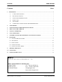
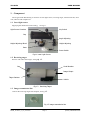
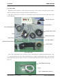
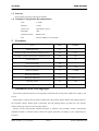
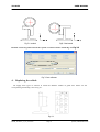
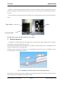
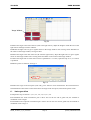
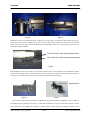
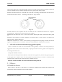
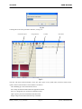
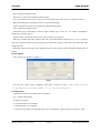
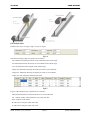
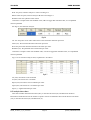
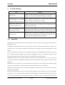
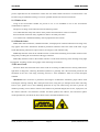
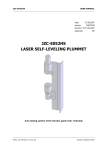
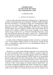
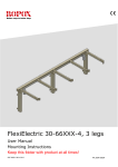
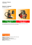
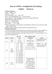
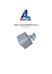
JD-A052
USER MANUAL
Number:
T/LT.T.02-2007
Version:
20070722
Date:
22.07.2007
Approved:
CE
JD-A052
T-TYPE GUIDE RAIL TESTING
MANU_JD-A052_T_en_001a.doc
©2008, LINGGAO GmbH
JD-A052
USER MANUAL
Contents
Sheet
1. COMPONENT ............................................................................................................................................... 1
1.1
LASER LIGHT SOURCE..........................................................................................................1
1.2
RECEIVING TARGET ..............................................................................................................1
1.3
IMAGE TRANSMISSION LINE ..............................................................................................1
1.4
DRIVE UNIT .............................................................................................................................2
1.5
SOFTWARE...............................................................................................................................3
1.6
COMPUTER CONFIGURATION RECOMMENDATION ......................................................3
2.
PARAMETER .....................................................................................................................................3
3.
INSTALLATION OF THE RECEIVING TARGET........................................................................3
4.
REPLACING THE VEHICLE ..........................................................................................................4
5.
MANUAL OPERATION ....................................................................................................................5
6.
AUTO OPERATION...........................................................................................................................6
7.
A-B ENDS ON-LINE MEASUREMENT (SUGGESTION OPTION) ............................................8
8.
SOFTWARE..........................................................................................................................................8
8.1 LAUNCH THE SOFTWARE ........................................................................................................8
8.2 SET OPTION ...............................................................................................................................10
8.3 DATA CHART .............................................................................................................................10
8.4 ANALYTIC DATA ...................................................................................................................... 11
8.5 ANALYTIC DATA CHART ........................................................................................................12
9.
TROUBLE SHOOTING....................................................................................................................13
10. ATTENTION .....................................................................................................................................13
11. SAFETY INSTRUCTION .................................................................................................................14
Hersteller:
Dalian Lat Laser Technical Development Co., Ltd.
Sales representation in Germany by:
Linggao GmbH
Tel:
An der Ling 27
Fax:
49-221-95754-34
50739 Köln Email:
[email protected]
49-221-95754-28
http://www.linggao.com
MANU_JD-A052_T_en_001a.doc
©2008, LINGGAO GmbH
JD-A052
USER MANUAL
1. Component
The T-type Guide Rail Testing is inclusive of laser light source, receiving target, transmission line, drive
unit, software and computer etc.
1.1 Laser light source
Supplying the datum line for the testing, see Fig1.1.
Light Source Cannister
Key Switch
Cap
Angle Adjusting
Height Adjusting
Height Adjusting Wheel
Base
Power Switch
Fig1.1 Laser Light Source
1.2 Receiving target
Receive and collect the images, seeing Fig 1.2.
Cap
Serial Number
Image Output
Target Canister
Vehicle
Fig 1.2
Receiving Target
1.3 Image transmission line
Connect the receiving target and computer, see Fig 1.3.
Fig 1.3 image transmission line
MANU_JD-A052_T_en_001a.doc
Page 1
©2008, LINGGAO GmbH
JD-A052
USER MANUAL
1.4 Drive unit
Supplied for auto operation, it makes that receiving target can be moved on the guide rail at uniform
speed; it is inclusive of drive control part and drive transmission part.
1.4.1 Drive control part is inclusive of Control Box, Forward limit sensor, Reverse limit sensor and
Control data line.
Control Data Line
Control Box
Auto Transmission Part
Forward Limit Sensor
Driver
Reverse limit sensor
Electromotor
Lock Hand Wheel
Adjuvant Transmission Part
Driven Wheel
Fig1.4 drive unit
1.4.2
Drive transmission part is inclusive of Auto transmission part, Adjuvant transmission part(Fig
1.4)and transmission steel wire. Auto transmission part is inclusive electromotor, driver and lock hand
wheel; adjuvant transmission part is inclusive of lock hand wheel and driven wheel; transmission steel line
as Fig 1.5
Metal Fastening Fittings
Metal
Bobbin
Bobbi
Fig 1.5 transmission steel line
MANU_JD-A052_T_en_001a.doc
Page 2
©2008, LINGGAO GmbH
JD-A052
USER MANUAL
1.5 Software
Image digital processing and analysis the data.
1.6 Computer Configuration Recommendation
2.
3.
CPU
1.5GHz
Memory
512M
Video card
DiectX9.0 or above
Hard disk
40G
Operation system
Windows XP
Port
Three of USB, one of serial port
Parameter
Item
Units
Standard
Measuring range
m
0—6
Primary surface measurement standard deviation
mm
0.03
Secondary surface measurement standard deviation
mm
0.05
measurement error
′
5
Laser wave length
nm
658
Laser output power
mw
<20
Relative humidity
%
≤75RH
Working temperature
℃
0—50
Working temperature
V
AA 1.5×4
Working current
mA
≤90
Weight
kg
6.1
Installation of the receiving target
Two kinds of placement for the receiving target: horizontal and vertical, place method to see Fig3.1 and
Fig 3.2.
While target is vertical, the top surface of guide rail is the primary surface and the side guiding surface is
the secondary surface. While target is horizontal, the side guiding surface of guide rail is the primary
surface and the top surface is the secondary surface.
Primary surface measurement standard deviation is 0.03mm, and secondary surface measurement
standard deviation is 0.05mm. Please choose the proper placement according to your requirement on
precision.
MANU_JD-A052_T_en_001a.doc
Page 3
©2008, LINGGAO GmbH
JD-A052
USER MANUAL
Fig 3.1 vertical
Fig3.2 horizontal
Remark: set the target direction in the “option” of software before measuring. See Fig 3.3
Fig 3.3 set software
4.
Replacing the vehicle
We supply three types of vehicles to match the different models of guide rails. Please see the
corresponding relationship, such as Fig 4.1.
Fig 4.1
MANU_JD-A052_T_en_001a.doc
Page 4
©2008, LINGGAO GmbH
JD-A052
USER MANUAL
Vehicle is connected with the target canister by one piece of board. Fasten it through three of bolts.
Please pay attention to the direction. See the Fig 4.2. Lay the vehicle on the connection board and screw
the bolts.
Easy operation for aiming at the bolt hole: align the foot and right borders of the vehicle and connection
board.
Vehicle
Target Canister
Connection Board
Fig 4.2
Remark: Please choose the right vehicle for every testing.
5.
Manual operation
Components for manual operation: laser light source, receiving target, image transmission line, software
and computer. The specific operation as follows
5.1 Install the laser light source (Call light source as follows). Seat the light source on the platform at the
distance of 600mm to the rail. Seeing Fig 5.1.
5.2 Please choose the proper according to your requirement on precision (refer to 3.installation of the
receiving target). Seat the target on the rail.
Fig 5.1 installation of the laser light source and receiving target
5.3 Connect the receiving target with computer by the image transmission line. Switch on and take off the
cap, launch the software then look at the image window.
MANU_JD-A052_T_en_001a.doc
Page 5
©2008, LINGGAO GmbH
JD-A052
USER MANUAL
Image Window
Fig 5.2
5.4 Move the target to the end of the rail (near to the light source), adjust the height to make the axis of the
light source and target canister collinear.
5.5 Rotate the light source to get a regular reticle on the image window. The crossing center should be on
the center of the image window, see Fig5.2 show.
5.6 Move the target to the end of the rail (far from the light source), adjust the light source to get a regular
reticle on the image window. The crossing center should be on the center of the image window.
5.7 Move the target back to check if the reticle is qualified as 5.5. If not, repeat the step of 5.5, 5.6 until it
is qualified.
5.8 Set the points in software, see Fig5.3.
Fig 5.3
5.9 Move the target to the first point (near end), press “hand” to start measurement. The measurement is
finished after the data shows on the sheet. Move the target to the next point, measure the points in turn.
6.
Auto operation
6.1 Operation step as follows 5.1, 5.2, 5.3, 5.4, 5.5, 5.6, 5.7, 5.8.
6.2 Installation the Auto transmission part of drive unit on the far end of guide rail, the method of
installation such as Fig6.1
6.3 Installation the Adjuvant transmission part of drive unit on the near end of guide rail, the method of
installation such as Fig 6.2.
MANU_JD-A052_T_en_001a.doc
Page 6
©2008, LINGGAO GmbH
JD-A052
USER MANUAL
Fig 6.1
Fig 6.2
6.4 Steel wire line is circled respectively on the driver (such as Fig 6.1) and driven wheel (such as Fig 6.2),
finally fix on the vehicles. Seeing Fig 6.3, there are four bolts on the vehicles, the top 2 bolts are used for
fixing steel wire line while vertical installation; the underneath 2 bolts are used for fixing steel wire line
while horizontal installation.
纵向测量固
Fix the steel wire while vertical measurement
定钢丝处
横向测量固
Fix
the steel wire while horizontal measurement
定钢丝处
Fig 6.3
6.5 Installation limit sensor. There are two kinds of limit sensor: Forward limit sensor and Reverse limit
sensor. Forward limit sensor is installed on the near end of guide rail (Adjuvant transmission part), Reverse
limit sensor is installed on the remote end of guide rail (Auto transmission part).
Regulating Nut
Fig 6.4
Fig6.5
Limit sensor ( Call sensor as follows) is adsorbed on the guide rail when installation ( such as Fig6.4),
and adjusting the regulating nut ( Fig6.5) , make sure the distance of green face and the vehicle is within
5mm. When user can’t judge if the distance is within 5mms, connect the sensor with the control box and
MANU_JD-A052_T_en_001a.doc
Page 7
©2008, LINGGAO GmbH
JD-A052
USER MANUAL
switch on the control box, if the indicator light of sensor is red and the sensor doesn’t touch the vehicle, the
sensor is installed correctly. Whereas adjusting the sensor properly until satisfy request.
6.6 Sensor and electromotor are connected with control box. According to the label hint, relevant slur are
inserted relevant faucet. Notice:According to direction of
Fig 6.6 shown.
Insert Alignment
图
Fig6.6
6.6
6.7 Link control box and computer. One end of control data line is inserted into control box ‘computer
correspondence’, another end is inserted com port of computer.
6.8 Switch on the control box, set it on ‘star’ and ‘forward’. Moving the vehicle on the near end of guide
rail.
6.9 Start the auto operation in software. Method is to click the button of ‘Auto measure’ in software (the
button will show ‘Manual operation’).
6.10 Set the control box on “reserve”. Auto measuring is testing until receiving target moved to the far end
of guide rail. Waiting for the “record data” shows the measured data, the measurement is finished.
7.
A-B ends on-line measurement (suggestion option)
There is a 200mm area which can’t be measured on auto operation, in order to solve this problem, we
suggest that the A-B ends on-line measurement, its principle is that two ends of guide rail are lengthened,
increasing examination area.
The specific method as follows:
Place a piece of short guide rail of 400mms on the near end of guide rail (called A end), placing a piece
of short guide rail of 500mm on the far end of guide rail (called B end), A, B ends are connected with
guide rail closely, make sure that vehicle can move smoothly in scope.
Remark: A.B ends should be the same model with measured guide rail.
8.
Software
8.1 Launch the software
Press ‘rail.exe’. See Fig 8.1. The series No. of product is inputted into the window, the software will
automatically load the calibration value from the database.
MANU_JD-A052_T_en_001a.doc
Page 8
©2008, LINGGAO GmbH
JD-A052
USER MANUAL
Fig 8.1
Clicking OK to the main procedure interface, see Fig 8.2.
Information Input
Image Window
Tool Bar
Data Sheet
Fig8.2
Tool bar (the entire function button): New file, print, print review, hand (auto) measure, hand record,
option, and exit. The function of each button is as follows:
New: Building up a new examination record.
Save: Keep examination data under the appointed content;
Save as: Change the save content of examination data;
Open: Open a previous examination data document;
Output: Output examination data directly in EXCEL.
MANU_JD-A052_T_en_001a.doc
Page 9
©2008, LINGGAO GmbH
JD-A052
USER MANUAL
Print: Printing examination data;
Print preview: Previewing the data before printing;
Auto: to match the drive device to carry on an auto measurement; (drive device is optional accessory)
Hand: Recording the examination result on every point manually;
Option: Setup the com, direction of Receiving Target and the points.
Exit: Closing the measure process.
Information input: information could be input includes type of the rail, rail model, manufacturer,
department, operator, time etc.
Image window: synchronal show the laser reticle of the receiving target.
Data area: includes data table, analytic data chart, and analytic data. Referred to 6.3, 6.4, 6.5. Analytic
data is the result of analysis and processing of the tested data. Analytic data chart is the data chart after
being analyzed.
Status bar: displays the status of set, including of the com port, points, target orientation and the status of
testing.
8.2 Set option
Press ‘option’ on software, see Fig 8.3.
Fig8.3
Set com port, points, target orientation. The scope of point is from 3~100. Please refer to
“3.installation of receiving target” to set the target direction.
8.3 Data chart
Explanation of the items of chart of the record data:
No. : Number of the points
D: distance to point 0
X: measured data of X-coordinate
Y: measured data of Y-coordinate
A: distortion (the angular of side working face and Y-coordinate, counter-clockwise is positive value)
MANU_JD-A052_T_en_001a.doc
Page 10
©2008, LINGGAO GmbH
JD-A052
USER MANUAL
8.4 Analytic data
Includes four parts, see Fig 8.4, Fig 8.5, Fig 8.6, Fig 8.7.
Fig 8.4
The items meaning of Fig 8.4 respectively as follows:
Xes: Maximum linearity deviations of X coordinate in the whole range.
Yes: Maximum linearity deviations of Y coordinate in the whole range.
Aes: maximum distortion angular in the whole range
Xepm max: Maximum linearity deviations per meter of X coordinate
Yepm max: Maximum linearity deviations per meter of Y coordinate
Aepm max: The maximum distortion per meter
Fig8.5
Fig 8.5 is B/A analysis form, explanation is as follows:
Measurement direction: horizontal direction or vertical direction
No.: Number of B/A value when there is not only one B/A.
B/A: analyzes result of B/A.
B value (mm): analyzes result of B value
A value (mm): analyzes result of A value
MANU_JD-A052_T_en_001a.doc
Page 11
©2008, LINGGAO GmbH
JD-A052
USER MANUAL
Point: the point, software analyzes A value according to it.
Datum mark: the point, software analyzes B value according to it.
Standard value: the qualified value of B/A.
Conclusion: Compare B/A with standard value, if B/A is bigger than standard value, it is unqualified
whereas qualified.
See Fig 8.6, the distortion analysis.
Fig8.6
No.: the start point of one meter where there is the maximum distortion per meter.
Value (′/m): the maximum distortion deviation per meter.
Point: the point with maximum distortion deviation per meter.
Standard (′/m): the qualified value of distortion per meter.
Conclusion: Compare result with standard value, if result is bigger than standard value, it is unqualified
whereas qualified.
Fig 8.7 is an assistance analysis form, explanation is as follows:
Fig8.7
图
8.7
Xe (mm): Deviations of X coordinate
Ye (mm): Deviations of Y coordinate
Xepm (mm): Deviations of X coordinate per meter
Yepm (mm): Deviations of Y coordinate per meter
Aepm (’): angular distortion per meter
8.5 Analytic data chart
This chart includes X direction deviation (Xe), Y direction deviation (Ye) and distortion deviation.
Horizontal coordination shows the number of points. Vertical coordination shows the X direction deviation
(Xe), Y direction deviation (Ye) and distortion (A).
MANU_JD-A052_T_en_001a.doc
Page 12
©2008, LINGGAO GmbH
JD-A052
9.
USER MANUAL
Trouble shooting
Cause
Remedy
No laser emit
Check whether the battery has enough power and whether the
polarity is correct; Check whether the lens cap is removed.
Laser reticle is not emit to the
receiving target or it is emitted
outside of computer image area
Check whether the light source is placed evenly, whether the
height and angle of the light source is proper.
Swing while spreading to move
a round to spread to move
The check spreads to move a direction and spreads to move axle
whether perpendicularity; The check locks a tight hand round
whether the lock is tight.
There is the abnormal sound or
not smooth movement
Check whether the target vehicle is placed evenly, whether the
hand wheel prop up the side of guide rail, whether there is any
foreign matter on the contact face of target vehicle and guide rail.
Abnormal data
Whether there is someone or something warding off the laser
beam, whether the support platform is shaken or rocked fiercely.
Check the power of battery and USB connected.
10.
Attention
10.1 Reticle are reflected by terrace and other objects to receive up the receiving target, will influence to
measure accuracy.
10.2 In the measured guide rail process, light source can’t drive other object interferences, collide or the
light beam cover, if the direction of light source changes in the testing, then this time diagraph as a result
invalid.
10.3
Light source uses four section No.5 alkaline dry batteries, the high performance battery can provide
for 8-12 hours’ the power supply use an electricity, suggesting to work in a row 8 replace battery in time
after hour. Otherwise weak of reticle will cause the abnormality of calculation data!
10.4 Must take out battery when the light source doesn’t work with long hours, so as not to result in to
decay inside machine; discarding the old battery please handle carefully, in order to prevent results in other
pollutions.
10.5 If there is an excrescent voice with switch and receiving target in the testing, please terminate testing
in time, and according to the exclusion method of the instrument to carry on a processing.
10.6 Receiving target parks in the safety stable appropriate position after once testing in order to prevent
damage receiving target.
10.7 The filter forbids to touch, row, touch and other pollutions. The instrument covers receiving target
protection a cover in time after using. If there is dust and fingerprint on filter during the testing, please use
to blow breeze ball to blow or wipe with the lens paper, avoid by all means to sweep by hand or blow with
MANU_JD-A052_T_en_001a.doc
Page 13
©2008, LINGGAO GmbH
JD-A052
USER MANUAL
the mouth.
10.8 The instrument should be placed in well ventilated and dry place, the attention defends tide. .If
instrument need not for a long time (more than one month), should be well ventilated once at least monthly.
Take instrument from the outdoors to inside in winter, should place a period of time again open a box, in
order to prevent knot dew inside machine, making electric appliances circuit short-circuit and influence
filter lift span.
10.9 The inside of receiving target and light source have stronger magnet. Be keeping off a computer,
cellular phone etc. the position of other electronics products, in order to prevent computer, the cellular
phone after using or stopping using.
10.10 Operator’s each part of body avoids coming up against to measure terrace, being measured to guide
rail, receiving target and each on-line in testing, otherwise will influence accuracy of measuring the result.
10.11 Avoid the sun blazed down on filter.
10.12 If the axletree of receiving target inferior extremity has more greasy dirt, can use alcohol or diesel to
clean.
10.13 If the rolling bearing of receiving target and magnet piece has damage and severity of deformation,
can’t carry on a normal testing.
11.
Safety instruction
The following directions should enable the person responsible for the JD T-type Guide Rails Testing,
and the person who actually uses the instrument, to avoid operational hazards in advance. The person
responsible for the instrument must ensure that all users understand these directions and adhere to them.
11.1 Use of the instrument
The permitted use of JD-A052 T-type Guide Rails Testing is the following:
A Measuring the straightness and distortion
B save, export and print the measuring data
11.2 Prohibited use
A .Using the instrument without instruction
B .Using outside the stated limits
C .Deactivation of safety systems and removal of explanatory and hazard labels
D .Opening of the equipment by using tools (screwdrivers, etc.), as far as not specifically permitted for
certain cases
E .Carrying out modification or conversion of the product
F .Under the environment of glare
G .Under the environment of fog or rain
WARNING: Prohibited use can lead to injury, malfunction, and material damage. It is the task of the
MANU_JD-A052_T_en_001a.doc
Page 14
©2008, LINGGAO GmbH
JD-A052
USER MANUAL
person responsible for the instrument to inform the user about hazards and how to counteract them. The
JD-A052 T-type Guide Rails Testing is not to be operated until the user has been instructed.
11.3 Limits of use
Using in the environment suitable for person to live in. It’s forbidden to use in the environment
combustible or explosive.
The person in charge of the instrument has the following duties:
A To understand the safety instructions on the product and instructions in the User manual
B To be familiar with local safety regulations relate to accident prevention.
C To inform LAT LASER immediately if the equipment becomes unsafe.
11.4 Hazards in use
11.4.1 When fault instrument, collided instrument, misemployed or reformed instrument are being used,
may appear false result. Instruments should be periodical examined. Notice the clean of JD-A051 T-type
Guide Rail Testing instrument’s optical mirror, the integrity of the machine body.
11.4.2 May therefore result in the mistake measure a result while measuring environment vibration more
and greatly. Avoiding the environment with bigger vibration.
11.4.3 May therefore result in the mistake measure a result while measuring in the dazzling strong light
environment. Avoiding creation strong light in the measuring environment.
11.5 Laser Grade
The laser which this instrument laser shoots send out is belongs to IIIB class laser. Seeing inside direct
light beam is dangerous; observing the diffuse reflection is generally safe. The instrument passed the CE
attestation of the TUV safe usage, matching EN61010-1:2001 EN60825-1:1994+A1+A2 the European
standard.
Admonition: The work area or protection round ingress of IIIB laser instrument, proper add to stick
homologous warning marking. Don’t orthoptic laser beam, using the eyes orthoptic laser beam will bring
bane to eyes, please wear a laser shielding Spectacles at any time while using. Do best to prevent ray
radiation possibly, mirror surface with have the radiation of potential danger(such as lens, triple prism, all
the surface reflection of transmission window and beam splitter).The reflector, lens and beam splitter
install possible firm, and when the laser shoots can be controlled ambulation only.
LASER APERTURE
MANU_JD-A052_T_en_001a.doc
Page 15
©2008, LINGGAO GmbH