1
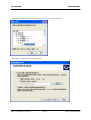
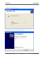
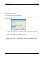
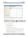
JZC-E052HS USER MANUAL Date 07.26.2007 Version 20070726 Number T/LT.T.04-2007 Approved CE JZC-E052HS LASER SELF-LEVELING PLUMMET Auto testing system of the elevator guide rails’ verticality MANU_JZC-E052HS_en_001.doc ©2008, LINGGAO GmbH JZC-E052HS Contents USER MANUAL Sheet 1 COMPONENTS.........................................................................................................................................1 1.1 JZC-E laser self-leveling plummet ................................................................................................1 1.2 SZ-A Auto Receiver ...............................................................................................................3 1.3 FJ11Digital Display Target ............................................................................................................3 1.4 Parameter .......................................................................................................................................4 2 OPERATION .............................................................................................................................................5 2.1 Operation of main body and Auto Receiver...................................................................................5 2.2 Operation of main body and Digital Display Target (FJ11)...........................................................6 3 MEASUREMENT COORDINATE AND READING ............................................................................6 4 RELAY MEASUREMENT .......................................................................................................................7 5 INSTALL THE SOFTWARE....................................................................................................................7 5.1 install the driver from CD ................................................................................................................... 7 5.2 Install the control software ............................................................................................................... 10 6 SOFTWARE OPERATION ...................................................................................................................10 6.1 Introduction of the software windows ............................................................................................10 6.2 Main interface introduction.............................................................................................................10 6.3 Set Options......................................................................................................................................14 6.4 Measuring with SZ-A Auto Receiver..............................................................................................14 6.5 Measuring with FJ11 Digital Display Target ..................................................................................15 6.6 Software instruction when relay measurement ...............................................................................15 7 ATTENTION AS FOLLOWS .................................................................................................................15 8 SECURITY INSTRUCTION..................................................................................................................16 8.1 Use Range of Instruments............................................................................................................16 8.2 Using of Restriction .....................................................................................................................17 8.3 The Responsibility of Instruments principals. .............................................................................17 8.4 Problems come alone in testing ...................................................................................................17 8.5 Laser Class...................................................................................................................................17 MANU_JZC-E052HS_en_001.doc ©2008, LINGGAO GmbH JZC-E052HS USER MANUAL 1. Components The instrument integrates the optical, mechanical and electric. Including the main body of JZC-E laser self-leveling plummet, the optional accessories of SZ-A Auto Receiver, FJ11 digital display target and software etc. 1.1 JZC-E laser self-leveling plummet Bubble Principal Switch Battery Fixer Double Adjustable Fig 1.1 JZC-E laser self-leveling plummet(see Fig1.1)transmits a visible laser plumb line with high precision. It is composed by laser transmitter, optical collimation、self-leveling system, power supply and circuit system and special fixer, adjusting wheel, bubble, shell etc. With the aid of Auto Receiver(see Fig 1.7) or digital display target (see Fig 1.8), the complete system can supply the function of testing verticality, linearity and parallelism of the elevator guide rails. The laser transmitter is semiconductor laser, wave length 658nm, output power<1mw, Class 2 laser device. The reaction of dodging (including wink) is safeguard for eyes. Consistent with National Standard of the People’s Republic of China《Radiation safety and classification of laser products, requirements and users guide 》 GB7247—1995 and European Standard EN61010-1:2001 EN60825-1:1994+A1+A2, certified by CE. JZC-E is a kind of safe laser product , the radiation of laser is harmless. JZC-E power is 3V (see Fig 2), two pieces of AA batteries could be used continuously for 35 hours safely and conveniently. 图 1.2 The principal part and basement could be rotated with 360° and there is the graduation of MANU_JZC-E052HS_en_001.doc Page 1 0°、90°、 ©2008, LINGGAO GmbH JZC-E052HS USER MANUAL 180°、270° on the principal part (see Fig 1.3). The white sign on the basement is the finger to point the graduation. User can easily make the self-inspection of the precision. The measurement error can be eliminated by rotating 180°(see Fig 1.4). Graduation Sign 图13 Roate180° Fig 1 4 The fixer is to fasten JZC-E instrument on the guide rail conveniently and the safety tether is to prevent the instrument from it’s falling (see Fig 1.5). There is the interface on the principal part to install the instrument on the tripod when it is used for other application. The weight of JZC—E principal part is 1500g which is easy to carry. Fig 1.5 The laser instrument is fitted with a liquid-based self-leveling system which guarantees the verticality and uncertainty is highest among the congener products. JZC adopts the special optical system (Spatial phase modular). So the laser beam is a group of light and shade concentric annulus which is a kind of big and clear contrast (see Fig 1.6). It eliminates the focusing MANU_JZC-E052HS_en_001.doc Page 2 ©2008, LINGGAO GmbH JZC-E052HS USER MANUAL error and improves the read precision that ensures the verticality and linearity inspection of the guide rails. Fig 1 6 1.2 SZ-A Auto Receiver SZ-A receives and acquires the images of every testing point and then transmit the images to the computer. It is conclusive of lens cap, filter, sunshade, connection, moving part, lock wheel, magnet, rolling bearing, transmission line etc. Sunshade Connection Lens Cap Moving Part Rolling Bearing Lock Wheel1 Magnet Fig 1.7 The moving part is available to most of models of guide rails. There is the rolling bearing and magnet. Rolling bearing can be close-contact with the guide rail under the effect of the magnet. The moving part can move on the guide rail along with the movement of lift car. Lock the Auto Receiver by lock wheel when it is on the testing point. 1.3 FJ11Digital Display Target FJ11 digital display target is composed by calipers, digital display vernier, prism, reticle, try power supply and special fixer etc. The length of verniers of X and Y is in the scope of 60mm×70mm, the angle of two veriner is 90°±6ˊ, read error 0.02mm, alignment error of laser beam on the prism is 0.1~0.2mm(to normal operator). MANU_JZC-E052HS_en_001.doc Page 3 ©2008, LINGGAO GmbH JZC-E052HS USER MANUAL Tray Reticle Fixer Prism Callipers Digital Fig 1.8 1.4 Parameter JZC-E Laser Self-leveling Plummet Standard deviation double-run plumbing Vertical precision in 1/200000 5″ Leveling compensator error 0.1″/1′ Bubble accuracy 8′ Wave length of laser 658nm Output power <1mW Global distance 1-150 m 100m ≤φ8mm 50m ≤φ3mm <15s Diameter of central beam Damping time Temperature of ambient 5~35℃ Humidity of ambient <90%RH Power DC Weight 3V 1.5Kg Digital display target FJ11 Working range 60mm×70mm Digital display veriner error 0.02mm Power of digital display DC 1.5V,AG 12 Auto Receiver SZ-A Working range 40mm×30mm Auto receiver error MANU_JZC-E052HS_en_001.doc ±0.05mm Page 4 ©2008, LINGGAO GmbH JZC-E052HS 2 USER MANUAL Operation Used for the elevator installation, elevator inspection and maintenance etc. Read carefully through the User Manual. 2.1 Operation of main body and Auto Receiver 2.1.1 Before using the laser instrument JZC, insert the batteries. 2.1.2 Fasten the main body on the top of the guide rail. The rail should be clean. The five pegs should be close-contact on the two faces of guide rail. Lock the wheel and fasten it on the rail (see Fig 1.5). The main body will not be moved again during the measurement unless the relay measurement is operated for the high building. 2.1.3 Drill the hole on the fixer and tie the tether on the bracket of guide rail against instrument falling down (see Fig 1.5). 2.1.4 Check if the bubble is on the center. Adjust the jacking bolts to center the bubble. 2.1.5 Switch off the lens cap and switch on the power. Hold a sheet of paper horizontally under the lens and check whether the light spot forms a circle. If the light point does not form a circle, the instrument must be removed again and moved gently back and forth. The fluid in the equipment will then congregate completely. 2.1.6 Take out the Auto Receiver (SZ-A) and check if there is damage and distortion on the bearings and magnet. It could not measure in case of bad damage or distortion. 2.1.7 Fasten the Auto Receiver about 100~200mm beneath the main body, the five rolling bearings should osculate wit the guide rail completely. The receiver should move on the rail body smoothly. Because the measurement of linearity is relative measurement. This point will be set as point zero. 2.1.8 Connect the Auto Receiver and computer by transmission line. 2.1.9 Open the cap of Auto Receiver. 2.1.10 Launch the software(elevator.EXE)for measurement (the instruction of software is Part 5). Pay attention to connect the line before launching the software. 2.1.11 Run the lift car at the speed of examining and repairing. Low and uniform speed. Stop the car at the first testing point and fasten the Auto Receiver on the point to measure it. 2.1.12 Turn the main body on the other guide rail according to step of 2. Rotate it with 180°. Measure the points according to steps of 3~11. 2.1.13 Turn off the power, disconnect the transmission line, cover the lens cap, clear all the components into the container. Finish the measurement. 2.1.14 Dealing with the data, see the instruction of software. MANU_JZC-E052HS_en_001.doc Page 5 ©2008, LINGGAO GmbH JZC-E052HS USER MANUAL 2.2 Operation of main body and Digital Display Target (FJ11) Steps of 1~5 is same with the steps of 1~5 in part 2.1 z Pass over the steps of 2.6-2.12 when using Digital Display Target (FJ11). z Take out the Digital Display Target (FJ11) and fasten it on the first point. Move the verniers to center the reticle with the laser spot. If the interference stripe is not clear, center the recicle by the outer loop of the spot. Set the digital display verniers of X and Y to be zero and this point is the origin. Record the data on the sheet. 3 z Continue the measurement for the following points. z Measure the other guide rail according to the steps of 2.14 and 2.15. z Put all components into the container. Finish the measurement. z Input the data to the software for analysis. See the instruction of software. Measurement coordinate and reading Coordinate of left guide rail Coordinate of shaft X Y Y O X Coordinate of right guide rail Fig 3.1 coordinates of Auto Receiver, Digital Display Target and the shaft The coordinates of Auto Receiver, Digital Display Target and shaft are different. SZ-A Auto Receiver and FJ11 Digital Display Target have the same coordinate. Pay attention to the orientation in the shaft and distinguish the left and right rail against confusion of data. Customarily for the shaft coordinate, the rail on the left is the left rail and the rail on the right is right rail when the inspector stands at the elevator door and faces to shaft. The direction of connecting two rails is Y and the upright direction to the Y is X. But when measuring, the coordinates for measurement and reading of the target is the relative one defined for every rail. It’s not according to the shaft coordinate. The relationship of the measurement coordinate and shaft coordinate, please refer to Fig 3.1. When using FJ11 Digital Display Target, please record the data with its positive sign or negative sign MANU_JZC-E052HS_en_001.doc Page 6 ©2008, LINGGAO GmbH JZC-E052HS USER MANUAL from the vernier. 4 Relay measurement After the numerous operation at site, the working range of JZC-E is 0~150 meters according to the various environment. The optimal working range is about 0-70 meters. Though the laser beam could be visible at more than 150 meters, the laser spot will be changed due to the swing of the high building and the libration of ambient. The centering error will be enlarged. User can operate the relay measurement to solve the problem and continue the measurement. So JZC can be sued for all high buildings. For example: the elevator is 120 meters, the laser spot is swinging clearly when the testing point is bracket No. 25. Take down the main body from the top and turn it on the bracket No. 23, fix the target on the bracket No. 24 and set the target to be zero. Continue the measurement from the bracket No.25. For example, the previous data for No. 24 is X:+2.5mm, Y:-3.20mm, after moving main body and setting zero at No. 24, the data of No. 25 is X:+0.10mm, Y:-0.20mm. And the final result of No. 25 is calculated as X25=2.50mm+0.10mm=2.60mm Y25=(-3.20mm)+(-0.20mm)=-3.40mm The rest points are calculated in the same way. 5 Install the software 5.1 install the driver from CD This driver is only for SZ-A Auto Receiver. Not available for FJ11 Digital Display Target. 5.1.1 Connect the Receiver and computer by USB, the window appears as following: MANU_JZC-E052HS_en_001.doc Page 7 ©2008, LINGGAO GmbH JZC-E052HS USER MANUAL 5.1.2 Select "Don't search ,I will choose the driver to install". Then click Next. 5.1.3 Select “\Target Drivers” and click “OK. MANU_JZC-E052HS_en_001.doc Page 8 ©2008, LINGGAO GmbH JZC-E052HS USER MANUAL 5.1.4 Select the position and click Next. 5.1.5 Wait for a while, there is the window as following: MANU_JZC-E052HS_en_001.doc Page 9 ©2008, LINGGAO GmbH JZC-E052HS USER MANUAL 5.1.6 Click “Finish”. The driver of the receiver is installed successfully. 5.2 Install the control software 5.2.1 Open folder of “software_eh” in CD disk, copy the folder “JZCE” to the computer. 5.2.2 Run JZCE.exe in “JZCE”. 6 Software operation 6.1.Introduction of the software windows Click “jzce.exe”, open window is for Login. Because there are two kinds of targets, user should select the proper one firstly. Fig 6.1 For SZ-A Auto Receiver, user need input serial No. (serial No. is on the Receiver), for example “SZ-A070003”. For FJ11 Digital Display Target, user needn’t input serial No. 6.2. Main interface introduction After selecting target, click “OK”, see Fig 6.2 Remark: “record”、“delete”、“options” and “select guide rail” is not available to FJ11 Digital Display Target. MANU_JZC-E052HS_en_001.doc Page 10 ©2008, LINGGAO GmbH JZC-E052HS USER MANUAL Fig 6.2 Main interface is composed by tool bar, input information, image area, data area and statusbar etc. z tool bar (see Fig 6.3): includes 12 buttons. Fig 6.3 new:create or delete current file. Save file: save current data. Open file:open previous document. print:print the data table and data chart. preview:preview the print. record:record the data while manual measurement. calculate:analyze the data. Analysis method: make fitted line based on the data of left rail using method of least squares. Then calculate the deviation of every testing point of left rail to the fitted line. After measurement of left rail, move the fitted line to the coordinate of the right rail and calculates the deviation of right rail. It is operated after complete testing. Delete:delete current data –data of last line. Relay:relay measurement. The different operation with two targets is introduced in the next MANU_JZC-E052HS_en_001.doc Page 11 ©2008, LINGGAO GmbH JZC-E052HS USER MANUAL part. z Option: set the pictures for every point. Quit: quit the programme. Input information and image area Input information see Fig 6.4. Image Area see Fig 6.5. Input information is for the information of project name, elevator No., producer, test dept., department, operator and time. Image Area: the image collected on the receiver is displayed on the image area synchronal. Fig 6.5 Fig 6.4 z Data area Include data table and data chart. Data table is for the data measured and deviation analyzed. See Fig 6.6. NO.: the number of testing point. X1: measured data in X direction of left guide rail. X2: measured data in X direction of right guide rail. Y1: measured data in Y direction of left guide rail. Y2: measured data in Y direction of right guide rail. XL1: deviation in X direction of left guide rail. XL2: deviation in X direction of right guide rail. YL1: deviation in Y direction of left guide rail. YL2: deviation in Y direction of right guide rail. MANU_JZC-E052HS_en_001.doc Page 12 ©2008, LINGGAO GmbH JZC-E052HS USER MANUAL Fig 6.6 Data chart: after measurement, it shows the deviation trend of X and Y direction (XL1, XL2, YL1, YL2) (See Fig 6.7). Fig 6.7 MANU_JZC-E052HS_en_001.doc Page 13 ©2008, LINGGAO GmbH JZC-E052HS z USER MANUAL Status bar It ‘s for SZ-A Auto Receiver to display the calculating time for every image. 6.3 Set Options Click “options”, window shows as Fig 6.8: Fig 6.8 To set the pieces of picture for every point, more pictures will bring higher precision. Also more pictures will take more time. Generally setting small number at the range of 30~40 meters to the main body. When far distance and intensive sway, set big number. The scope is 1—50. User can change the option during measurement. For example, set 1 for former 20 points, set 5 for 20~30 points, set 10 for rest points after No.30. “Options” is not available for FJ11 Digital Display Target. 6.4 Measuring with SZ-A Auto Receiver 6.4.1 Connect the receiver and computer with transmission line, launch the software. When there is wrong connection or disconnection, the window Fig 6.9 will appear. Fig 6.9 When this window appears, check the transmission line and then launch the software again. If there is no problem, laser spot will show on the image area. See Fig 6.5 6.4.2 Start measurement Click “record” at every testing point, the software records the data in the data table. 6.4.3 After measurement of two rails, click “calculate”, the software calculates the deviation. MANU_JZC-E052HS_en_001.doc Page 14 ©2008, LINGGAO GmbH JZC-E052HS USER MANUAL 6.4.4 User can save the data table and data chart and preview it and print it. 6.5 Measuring with FJ11 Digital Display Target When using FJ11 Digital Display Target, user records the data on the book or sheet and input them to the data table of the software, then click “calculate”. The software calculates the deviation. User can save the data table and data chart and preview it and print it. 6.6 Software instruction when relay measurement 6.6.1 SZ-A Auto Receiver: operation see Part 4 Relay measurement. For example relay the measurement at point No. 25, move the main body to No. 23, remeasure the point No. 24. Before the operation of remeasuring, click the “relay” on the interface and there will be “R” on the No. 24 to sign it as relay point (see Fig 6.10). Click “record” to start the measurement , remeasurement on point No. 24 will not change the previous data of point No.24. Move the receiver to the rest points to continue the measurement. 6.6.2 FJ11 Digital Display Target: for example the relay measurement is from point No. 25, input the data of former points to the software, then click “relay”, the “R” in front of point No. 24 is signed as relay point. Input the data of rest points which are measured by relay measurement. The data (X=0,Y=0) of remeasurement on point No. 24 is not needed to be input into the software. Fig 6.10 7 Attention as follows 7.1 Forbid direct view laser bean when testing, in case of causing harm for eyes. 7.2 This testing result is void if light souse is interfered, collided or covered by others. 7.3 The precision of testing result is direct affected If Laser Self-leveling Plummet and computer are power supply insufficient. Please maintain power sufficiently. 7.4 When Laser Self-leveling Plummet doesn’t work for a long time, make sure that batteries are taken out. In case of corrupting instrument. The disused battery should handled in a proper way, in case of contaminate the environment. 7.5 Filter forbid touching, scratching and touching other pollutions. The filter and dust-proof protective cap should be cover timely at the end of using instruments. If there is a little dust and fingerprint on filter when MANU_JZC-E052HS_en_001.doc Page 15 ©2008, LINGGAO GmbH JZC-E052HS USER MANUAL using it. Please blew the dust off the glasses by blast ball, avoid sweeping with hand and blowing with mouth. The hard coat of precision optical instrument would be easily destroyed by using impropriety or unnecessary cleaning way and the capability may be reduce. 7.6 Taking the instrument and putting on it correctly and keeping it in the special container. This will reduce clean time and possibility of destroyed components. 7.7 Instruments should be kept in dry place and exposure to air for freshening and be kept off moisture. If instruments don’t use for a long time (above one month), exposure to air for freshening at least once a month. 7.8 Stockpile temperature is better within 10°C~40°C, instruments should avoid depositing in same room with corrosive medium. When instruments are taken from outside to indoor in winter and should be unpacked the case after depositing for a while, in case there is a little dew on instrument inside, it will cause that cords of electrical appliances short circuited and filter will be shortened lifespan. 7.9 Auto Receiver have strong magnetism, it had better deposit far from computers, in case of magnetization computers, affecting computers’ capability and using life-span. 7.10 Auto Receiver should be avoided direct irradiation of sun’s ray and attention water proof. 7.11 If Auto Receiver hasn’t been used for a long time and there is a lot of oil and filth under it, the Auto Receiver could be clean by gasoline or diesel oil. 8 Security Instruction The instruction could make principals and users who use Elevator Guider Rails Self-leveling Plummet Testing acknowledge any complexions of occurred and danger, in order to taking some precautionary measure in advance. Principals should make sure that all users must read and follow this catalogue. 8.1 Use Range of Instruments 8.1.1 Use Rang of Appointed Laser Self-leveling Plummet’s use range of appointed as follows: z Guide Rail of Plummet and Linearity Testing z Storage, educing and print the testing result. 8.1.2 Forbidden Range z Startup instrument without reading specifications. z Using instruments out of the range of Use Range of Instruments z Destroyed security system, taken out instruction or danger sign. z Opening instruments with tool(e.g. screwdriver) MANU_JZC-E052HS_en_001.doc Page 16 ©2008, LINGGAO GmbH JZC-E052HS USER MANUAL z Updating or rebuilding instruments z Testing under the dazzle of the sunlight environment z Testing under the open air, mist and rainfall environment. 8.1.3 Warning When using forbidden way, it would cause failure, loss and people injury. Instrument principles should explain fatalness and how to prevent to users. Instruments don’t be worked before not ferreting out Laser Self-leveling Plummet’s method of application. 8.2 Using of Restriction Environment: Using in fit condition of life and not usable under the inflammable and explosive environment. 8.3 The Responsibility of Instruments principals. Warning: Instruments principals must guarantee to operate the instrument comply with the instruction. The responsibility of Instruments principals as follows: z Must know products of safety notice and instruction of using catalogue. z Must acquaint Safety Operational Rule during in the work. z Once instrument occurred the familiar malfunction, please contact with manufacturer----Lat Laser Company as soon as possible. Tel:+86-411-87638648 8.4 Problems come alone in testing 8.4.1 It maybe appear wrong result when using failure instrument, impacted instrument, misuse instrument and rebuilt instrument. Preventive Measure: Inspected instrument periodically. Keeping optical glass of Laser Self-leveling Plummet clean and keeping the body’s integrality. 8.4.2 Faulty safety precautions or insecurity measure, e.g. When guide rail is moving with nonstandard in testing, it would cause injury people. Preventive Measure: Attending testing environment is safe and flawless safety measures. 8.4.3 It maybe appears wrong result when testing with shake environment. Preventive Measure: Avoiding testing in shaking environment. 8.4.4 It maybe appears wrong result when testing with resplendent light environment. Preventive Measure: Avoiding testing with resplendent light environment. 8.5 Laser Class This instrument belongs to II genus laser products. II Genus Laser Products: MANU_JZC-E052HS_en_001.doc Page 17 ©2008, LINGGAO GmbH JZC-E052HS USER MANUAL It’s dangerous to watch inside light bean directly. It’s general safety to observe the diffuse reflection. Warning Sign: Workaround of II genus laser products and the entrance of enclosed protection had better attach relevant warning sign. Warning one: It’s harmful for eyes to watch laser light beam directly. Preventive Measure: Not watch laser light beam directly. Wearing laser-light protective goggles at any moment. Warning two: The surface of mirror reflection with potential danger appeared on the projected optical elements (e.g. lens, prism, transmission window, beam splitter) and radiation with potential danger could be transferred by a little reflective optional elements. Preventive Measure: Try to avoid accidental mirror reflection of laser radiation. Reflector , lens and beam splitter are tried to be made secure and when laser is sending, it is only under the controlled remove. Producer: Dalian Lat Laser Technical Development Co., Ltd. Sales representation in Germany by: Linggao GmbH An der Ling 27 50739 Köln Tel: Fax: 49-221-95754-34 49-221-95754-28 Email: [email protected] http://www.linggao.com MANU_JZC-E052HS_en_001.doc Page 18 ©2008, LINGGAO GmbH