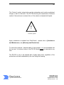
1
USER MANUAL
and
PROGRAMMING GUIDE
FiberControl
Polarization-Independent
Polarization State Scrambler
PS-700
FiberControl
Lightwave Polarization Solutions
1-888-91-FIBER toll free
732 332-1860 telephone
732 332-1861 facsimile
[email protected] email
www.fibercontrol.com web
ii
Please Note:
With the understanding and the desire of improving the clarity and readability
as well as to reduce omissions and correct errors, the information within this
manual is subject to change without notice.
FiberControl shall not be liable for any errors herein or for any accompanying
or subsequent damage in connection with the furnishing, operation, or use of
this material. With regard to this material, FiberControl makes no warranty
regarding the suitability and fitness for any specific function, purpose, or use.
Base FiberControl part number: PS-700
Printed: 16-May, 2002
© Copyright FiberControl 2002
All rights reserved
FiberControl
Lightwave Polarization Solutions
1-888-91-FIBER toll free
732 332-1860 telephone
732 332-1861 facsimile
[email protected] email
www.fibercontrol.com web
iii
FiberControl’s goal is to produce the best-valued Lightwave Polarization
Solutions© to meet a wide range of applications in the field of optical
measurements. We greatly value input from our customers with ideas to improve
and enhance our existing products as well as expand our product-line. Please
feel free to offer your ideas and/or criticisms. We look forward to hearing from
you and in meeting your needs in the field of polarization.
– The Staff of FiberControl
FiberControl
Lightwave Polarization Solutions
1-888-91-FIBER toll free
732 332-1860 telephone
732 332-1861 facsimile
[email protected] email
www.fibercontrol.com web
iv
Warranty and Restrictions:
FiberControl (FC) warrants material and production of the PS-700 for a period of
12 months from the shipping date. During this warranty period, FC will see to
defaults arising from manufacturing via direct repair or replacement at FC’s
discretion. For warranty repairs or service, the unit must be sent back to FC
(U.S.A.) or to a place determined by FC. The customer will be responsible for
shipping costs to FC, and in case of warranty repairs, FC will cover the shipping
costs back to the customer. If no warranty repair is applicable, the customer will
be responsible to return shipping expenses. In case of shipment from outside the
United States, all duties (taxes, etc.) arising from the transfer will be the
responsibility of the customer.
FC warrants the hard-, firm-, and software designed by FC for this unit to operate
fault-free if they are handled according to our requirements. However, FC does
not warrant a fault-free and uninterrupted operation of the unit, of the soft-, firmor hardware, for any specific or special application(s) nor this instruction manual
to be error free. FC is not liable for consequential damages.
The warranty mentioned before does not cover errors and defects being the
result of improper treatment, software, or interface not supplied by us,
modifications, misuse or operation outside the defined ambient stated by us or
unauthorized maintenance. All further claims will not be consented to and will not
be acknowledged. FC does not explicitly warrant the usability or the economical
use for any application.
FC reserves the right to change this instruction manual or the technical data of
the described unit at any time. Removal of any of the top and/or bottom
enclosure cover’s screws even in only an effort to gain entry inside the enclosure
nullifies the PS-700’s warranty and incurs the risk of physical harm.
FiberControl
Lightwave Polarization Solutions
1-888-91-FIBER toll free
732 332-1860 telephone
732 332-1861 facsimile
[email protected] email
www.fibercontrol.com web
v
Contact Information:
United States of America
FiberControl
P.O. Box 198
Holmdel, New Jersey 07733
phone: +1-732-332-1860
toll-free: +1-888-91-FIBER
fax: +1-732-332-1861
email: [email protected]
Web: http://www.fibercontrol.com
Call to obtain the ‘ship to’ address.
Outside the U.S.A.
Several distributors throughout the world also represent FiberControl. Please
refer to our web site or call our US based offices to ask for the nearest
distributor.
FiberControl
Lightwave Polarization Solutions
1-888-91-FIBER toll free
732 332-1860 telephone
732 332-1861 facsimile
[email protected] email
www.fibercontrol.com web
vi
Assistance and Maintenance:
Calibration, service, and maintenance agreements for the PS-700 are available
from FiberControl. Assistance for proper product usage is also available.
Feel free to contact FiberControl via phone, fax, and/or email for assistance.
FiberControl
Lightwave Polarization Solutions
1-888-91-FIBER toll free
732 332-1860 telephone
732 332-1861 facsimile
[email protected] email
www.fibercontrol.com web
vii
Hazard and Warning Labels/Symbols:
The following symbols have been placed at various points on the PS-700. To
ensure personal safety of users and those around them, the user must be
familiar with their meaning before operating the unit.
Assistance is available from FiberControl – see §Assistance and Maintenance,
and §Warranty and Restrictions.
These symbols signify posted warnings where extreme caution is required,
therefore, it is not recommended to proceed past them into the enclosure. These
symbols do not imply that FiberControl recommends the user to proceed inside
the enclosure but instead that if the user does choose to proceed, it must be with
great caution. Moreover, entry into the enclosure not only incurs the risk of
physical harm, but also nullifies the PS-700‘s warranty.
Placed on the back of the PS-700 is the following “Caution High Voltage” symbol.
This symbol, shown as a lightning bolt inside an equilateral triangle, warns of the
presence of “life-threatening” voltages inside of the enclosure if entered by the
user.
"Caution High Voltage" symbol
On the inside of the PS-700, the locations of these “life-threatening” voltages are
not specifically marked. Therefore, significant and meaningful personal physical
risk is present for anyone not completely familiar with the PS-700’s’ design. The
level of risk also holds true for the measurement and test equipment of the user.
FiberControl
Lightwave Polarization Solutions
1-888-91-FIBER toll free
732 332-1860 telephone
732 332-1861 facsimile
[email protected] email
www.fibercontrol.com web
viii
The “Caution” symbol, shown below as the exclamation point inside a equilateral
triangle, is also on the back of the PS-700 denoting the requirement of extreme
caution if the enclosure is entered into or if the exterior is cleaned with liquids.
!
"Caution" symbol
Again, assistance is available from FiberControl – please refer to §Assistance
and Maintenance, and §Warranty and Restrictions.
To insure the personal / physical safety of the operator, it is recommended that
the top and / or bottom covers of the PS-700 should never be removed at any
time.
The PS-700 is only to be cleaned with a lightly damp cloth, regardless of the
precautions and care undertaken by the user doing the cleaning.
FiberControl
Lightwave Polarization Solutions
1-888-91-FIBER toll free
732 332-1860 telephone
732 332-1861 facsimile
[email protected] email
www.fibercontrol.com web
ix
Ground Label/Symbol:
Located on the inside of the PS-700, near the power supply, is the symbol for the
“Protective Earth,” shown below. This ground symbol is placed next to the
green/yellow striped ground wire that attaches near the power supply on the side
of the enclosure and the ground connection on the power entry module.
Consistent with CE marking requirements, this procedure ensures that all metal
portions of the enclosure are properly grounded.
"Protective Earth" symbol
Despite the grounding design and procedure, the outside enclosure of the PS700 is only to be cleaned with a lightly damp cloth, regardless of the precautions
and care undertaken by the user doing the cleaning,
FiberControl
Lightwave Polarization Solutions
1-888-91-FIBER toll free
732 332-1860 telephone
732 332-1861 facsimile
[email protected] email
www.fibercontrol.com web
x
High-Level View of this User Guide:
The FiberControl PS-700’s User Manual and Programming Guide is organized as
follows:
Section 1
Section 2
Section 3
Section 4
Section 5
Appendix A
Setup and Preparation
Specifications and General Information
General Concepts and Applications
Front and Rear-Panel Description
Remote Operation: The PS-700 Command Set
Key Operations, Quick Reference
FiberControl
Lightwave Polarization Solutions
1-888-91-FIBER toll free
732 332-1860 telephone
732 332-1861 facsimile
[email protected] email
www.fibercontrol.com web
xi
Table of Contents
1
Setup and Preparation ................................................................. 1
1.1
1.2
2
3
Specifications and General Information ....................................... 4
General Concepts and Applications ............................................. 8
3.1
3.2
3.3
3.4
3.5
4
Tabletop Unit ..........................................................................................1
Rack Mounting the Tabletop Unit ...........................................................2
Introduction.............................................................................................8
Applications ............................................................................................9
Representations of the rapidly scrambled SOPs ....................................9
Design Background ..............................................................................11
Principle of Operation ...........................................................................12
Front and Rear-Panel Description.............................................. 17
4.1
General.................................................................................................17
4.2
Front-Panel Indicators, Rear-Panel Interface .......................................18
4.2.1
General Usage, Powering-up and Powering-down........................18
4.2.2
Optical Interface ............................................................................21
4.2.3
Remote Control and its Connections .............................................21
4.3
Rear-Panel Marking and Fusing Information ........................................24
5
Remote Operation: The PS-700 Command Set......................... 25
5.1
General.................................................................................................25
Appendix A: Key Operations, Quick Reference................................ 28
FiberControl
Lightwave Polarization Solutions
1-888-91-FIBER toll free
732 332-1860 telephone
732 332-1861 facsimile
[email protected] email
www.fibercontrol.com web
xii
Tables
Table 1: Optical specifications ..............................................................................4
Table 2: Instrumentation control............................................................................5
Table 3: Line power and temperature ...................................................................6
Table 4: Physical characteristics of the PS-700....................................................6
Table 5: SCPI command tree of PS-700 with ICS Electronics Model 4864. .......26
Table 6: PS-700 Scrambling Control (with Form B relays)..................................26
FiberControl
Lightwave Polarization Solutions
1-888-91-FIBER toll free
732 332-1860 telephone
732 332-1861 facsimile
[email protected] email
www.fibercontrol.com web
xiii
Figures
Figure 1: One of the two (left-hand side) rack-mounting brackets for the PS-700.2
Figure 2: Front-on view detailing dimensions of the rack-mount capability of the
PS-700...........................................................................................................3
Figure 3: Top-down view of the partially assembled rack-mounting brackets. ......3
Figure 4: Experimental data of the scrambled output displayed as a polarimetric
plot on the Poincaré Sphere and on the Observable Polarization Sphere. ..10
Figure 5: Experimental data showing the distribution of the frequency
components of the scrambling with the scrambler on and off. .....................11
Figure 6: Basic piezo-electric (PZT) tube shown with fiber wrapping..................13
Figure 7: Cross sectional view of PZT tube with fiber wrapping..........................14
Figure 8: Details of stress induced birefringence in the fiber. .............................14
Figure 9: Block diagram showing the basic internal structure. ............................15
Figure 10: Front view of PS-700. ........................................................................17
Figure 11: Rear view of PS-700. .........................................................................17
Figure 12: Rear panel depiction with an oval highlighting the location of the on-off
power switch. ...............................................................................................18
Figure 13: Depiction of front panel with an oval highlighting the location of the
green LED that indicates the unit is powered up..........................................19
Figure 14: Front panel depiction with an oval to highlight the location of the GPIB
status LEDs. ................................................................................................20
Figure 15: Depiction of PS-700’s front panel with highlighted oval showing the
locations of the optical input/output connectors. ..........................................21
Figure 16: Rear panel depiction with an oval highlighting the location of the GPIB
interface. ......................................................................................................22
Figure 17: Line voltage and fusing information located on the rear-panel of the
PS-700.........................................................................................................24
FiberControl
Lightwave Polarization Solutions
1-888-91-FIBER toll free
732 332-1860 telephone
732 332-1861 facsimile
[email protected] email
www.fibercontrol.com web
1
1 Setup and Preparation
1.1 Tabletop Unit
The PS-700 was designed primarily as a tabletop unit. Four small rubber pads
have been placed at the corners on the underside providing anti-skid protection
and to protect the table’s surface.
While the placement of these rubber pads was chosen for upright positioning on
a lab-bench, the PS-700 can be oriented in any desired direction, i.e., upside
down or on any of its sides, with the only caveat being the equipment’s secure
placement to ensure the safety of the end-user as well as others.
Plug the appropriate end of the provided power cord into the PS-700’s IEC-320
receptacle and the other end into a properly grounded electrical outlet. Press the
power rocker switch, located on the back panel, to the ‘I’ position to turn-on the
power to the unit.
With the unit secured in place, the optical fibers can be attached. See §4.2.2.
FiberControl
Lightwave Polarization Solutions
1-888-91-FIBER toll free
732 332-1860 telephone
732 332-1861 facsimile
[email protected] email
www.fibercontrol.com web
2
1.2 Rack Mounting the Tabletop Unit
While the PS-700 polarization scrambler has been designed primarily for the
tabletop, it can also be rack mounted. This section discusses details about the
mounting brackets.
The rack-mounting hardware for the PS-700 consists of two brackets attached on
each side near the front panel and is provided standard from the factory. Each
rack-mounting bracket is attached by a pair of #10-32 by 3/8” stainless steel flathead screws. These two mounting brackets can be easily removed using a #2
Phillips head screwdriver.
Below in Figure 1 is shown the top-down view of the unattached rack-mounting
bracket and hardware (i.e., #10 flat head screws).
#10 FLAT HEAD SCREWS (2)
RACK MOUNT BRACKET
FRONT PANEL
Figure 1: One of the two (left-hand side) rack-mounting brackets for the PS-700.
FiberControl
Lightwave Polarization Solutions
1-888-91-FIBER toll free
732 332-1860 telephone
732 332-1861 facsimile
[email protected] email
www.fibercontrol.com web
3
As shown in Figure 1, these two rack-mounting brackets are attached towards
the front panel on the left and right-hand sides with #10 flat head screws.
Figure 2 and Figure 3 show the front-on and top-down views, respectively, of the
PS-700 with the rack mounting brackets unattached and partially attached,
respectively. The PS-700 arrives from the factory with rack-mounting brackets
already attached; on delivery, the PS-700 is ready for mounting to an industry
standard 19” equipment rack rails.
PS-700
Polarization-State Srambler
2.75
INPUT
OUTPUT
OPTICAL
RDY
TALK/TX
LSTN/RX
SRQ/SRM
ERR
FiberControl
Industries
Figure 2: Front-on view detailing dimensions of the rack-mount capability of the PS-700.
12.000
12.785
16.740
18.932
Figure 3: Top-down view of the partially assembled rack-mounting brackets.
FiberControl
Lightwave Polarization Solutions
1-888-91-FIBER toll free
732 332-1860 telephone
732 332-1861 facsimile
[email protected] email
www.fibercontrol.com web
4
2 Specifications and General Information
Table 1: Optical specifications
Optical Specifications
Insertion-Loss (typical) 1
Coverage of Poincaré Sphere
Degree-of-Polarization
Polarization Dependent Loss 2
Wavelength Operating Range
Connector Types
Return Loss (Connector polish)
1
2
3
4
Max. Signal Power 3
Scrambling Rate 4
Residual AM Modulation
< 1.00 dB
90% to 99% (near pseudo-random)
< 5%
< ± 0.002 dB
1300 nm to 1600 nm,
or 980 nm region
FC, SC, or Bare Fiber
> 50 dB (0°)
> 60 dB (8°, fusion splice)
+ 30 dBm
4 MHz
< 0.1%
1550 nm with connectors
1550 nm, FC/PC connectors
Below SRS limit (SBS limit determined by the spectral broadening of user’s source)
Measured at the –10dB point from near uniform electrical rf spectral distribution
FiberControl
Lightwave Polarization Solutions
1-888-91-FIBER toll free
732 332-1860 telephone
732 332-1861 facsimile
[email protected] email
www.fibercontrol.com web
5
Table 2: Instrumentation control
INSTRUMENTATION CONTROL‡
Parallel Control Interface
GPIB (IEEE 488.2), 1 port
Response Time†
≤ 5 msec
Software Compatibility
w/ GUI interface
System Controller
GPIB Controller / Processor
Labview 6.0, or any other GPIB
capable development environment
Embedded EBX w/ microcontroller, ICS
Elect., Model 4864
National Instruments / µPD7210
Make/Break Contacts
Six independent high-current relays
Host Operating Systems
Windows 95, Windows 98, Win NT 4.0,
Win2000 Pro, Windows XP
Front Panel Control Interface
Display
LED Indicators
RDY
TALK
LSTN
SRQ
ERR
‡
†
None
Yes
Yes
Yes
Yes
Yes
– refer to ICS Elect. Owner’s manual
– following GPIB standard (IEEE-488.2)
FiberControl
Lightwave Polarization Solutions
1-888-91-FIBER toll free
732 332-1860 telephone
732 332-1861 facsimile
[email protected] email
www.fibercontrol.com web
6
Table 3: Line power and temperature
LINE POWER / TEMPERATURE
Electrical Input Voltage
85 VAC – 264 VAC, auto-switching
Line Frequency
47 – 63 Hz
Power Dissipation (nominal)
45 W
Fusing Requirements
1 Amp
Power Receptacle
IEC 320
Power Supply Efficiency (nominal)
82 %
Operating Temperature
– 10 °C to + 35 °C
Table 4: Physical characteristics of the PS-700
PHYSICAL
Dimensions
Weight
Overall H x W x D
(Metric)
Overall H x W x D
(English)
Enclosure
Height
Enclosure
Width
9.2 x 48.1 x 32.5 cm
3⅝ x 18.9 x 12.8 "
2U
83.7HP
34.6 N (3.53 kg)
7.79 lbs.
Note:
•
Overall heights (H) of desktop units include the presence of skid-resistant rubber pads located on the
bottom panel, 0.32 cm (1/8 ”) thick.
•
Overall widths (W) of rack-mount units include mounting hardware.
•
Enclosure height and width are related to the enclosure only – does not include the rack-mounting
hardware or skid-resistant rubber pads.
•
1U = 4.44 cm (1 3/4 “)
•
1HP = 0.51 cm (0.2 “)
FiberControl
Lightwave Polarization Solutions
1-888-91-FIBER toll free
732 332-1860 telephone
732 332-1861 facsimile
[email protected] email
www.fibercontrol.com web
7
Declaration of Conformity
Declaration de Conformité
Konformitätserklärung
FiberControl
P.O. Box 198
Holmdel, New Jersey 07733
U.S.A.
declares under its own responsibility, that the product:
Polarization-Independent Polarization-State Scrambler, PS-700
conforms to the following product Directives and Standards:
Safety:
73/23/EEC, 1973
93/68/EEC, 1993
EN 60950: 1992
Low Voltage Directive
Including amendments to above LV Directive
Standard, including amendments 1, 2, 3, 4, and 11
EMC:
89/336/EEC
EN 50081-1, 1992
EN 55022, 1998
EN 61000-3-2, 1995
EN 61000-3-3, 1995
EMC Directive
Standard, Electromagnetic Compatibility – emissions
Standard – Radio disturb., information technology equipment
Standard – Harmonic current emissions
Standard – Voltage fluctuation and flicker emissions
EN 50082-1, 1997
EN 61000-4-2, 1995
EN 61000-4-3, 1995
EN 61000-4-4, 1995
EN 61000-4-5, 1995
EN 61000-4-6, 1995
EN 61000-4-11, 1995
Standard, Electromagnetic Compatibility – immunity
Standard – Electrostatic discharge immunity
Standard – Radiated, r-f, e-m field immunity
Standard – Electrical fast transient/burst immunity
Standard – Surge immunity
Standard – Conducted immunity
Standard – Voltage dips and interruptions immunity
Supplementary Information:
Since this product conforms to the requirements of the Low Voltage Directive 73/23/EEC and the EMC
Directive 89/336/EEC, the PS-700 carries the CE marking.
Declaration of Conformity originally conducted by F-Squared Laboratories, Damascus, MD 20872 (Report
#2227-01, Issue Date: 12-21-2000). Subsequently, switcher replaced Power-One linear power supply.
Holmdel, New Jersey, USA
20, February 2002
J. D. Evankow, Jr. / MTS
FiberControl
Lightwave Polarization Solutions
1-888-91-FIBER toll free
732 332-1860 telephone
732 332-1861 facsimile
[email protected] email
www.fibercontrol.com web
8
3
General Concepts and Applications
3.1 Introduction
This manual describes the operation and specifications of FiberControl’s
Polarization-Independent Polarization State Scrambler, PS-700.
The PS-700 rapidly alters the state-of-polarization (SOP) of light within singlemode optical fibers in a pseudo-random manner. It provides a simple userfriendly front panel interface for direct interaction, as well as remote computer
control via GPIB 488.2. Moderately rapid short-term variations of output SOPs is
inherent in this technique. The PS-700 is capable of altering the SOP over a wide
range of wavelengths while minimally impacting the other optical parameters:
•
•
•
Ultra-low insertion loss,
Ultra-low reflection, and
Ultra-low PDL.
Based on techniques originally developed by Hervé C. Lefèvre at Stanford
University1, the PS-700 utilizes time-varying stress-induced birefringence to alter
the SOP of the polarized components of light.
With one continuous length of optical fiber secured onto six independent piezoelectric tubes, each receiving an r.f. drive voltage via a novel patented method2,
a time-varying birefringence is imparted into the fiber. Multiple sections of the
fiber receive spatially distributed sets of stress. These provide polarization
independent operation. In other words, the scrambler’s capability to provide a
fast and near uniform distribution of output Stokes’ vectors does not depend of
the input SOP.
Alternative SOPs appearing at the input of the PS-700 result only in altering the
scrambling path and continues to provide near uniform, but different, coverage of
Stokes’ 3-space (e.g., the Poincaré sphere).
1
2
USPTO #4,389,090
USPTO #20020037127
FiberControl
Lightwave Polarization Solutions
1-888-91-FIBER toll free
732 332-1860 telephone
732 332-1861 facsimile
[email protected] email
www.fibercontrol.com web
9
3.2 Applications
Many applications exist for the PS-700, a few examples are:
•
•
•
•
•
PDL system and component measurements,
Moderate/High-speed polarization scrambler,
As a component in a PMD emulator or compensator,
Semiconductor optical amplifiers measurements, and
General use throughout the laboratory.
3.3 Representations of the rapidly scrambled SOPs
The control and manipulation of the SOP is fundamental within the field of optics.
At the PS-700’s output, a scrambled SOP is provided. For those involved in fiberoptic research, development, and manufacturing, utilizing these rapid variations
in SOP is at the heart of many applications.
The displayed image of Figure 4 shows an example of scrambled experimental
data. Two representations of the Stokes parameters are plotted in 3-space (i.e.,
Poincaré Sphere and the Observable Polarization Sphere – both of which are
equivalent from the standpoint of representing the data). The Poincaré
representation is quite common. For both spheres, the data points plotted in red
corresponds to front surface of the sphere; blue the back surface.
FiberControl
Lightwave Polarization Solutions
1-888-91-FIBER toll free
732 332-1860 telephone
732 332-1861 facsimile
[email protected] email
www.fibercontrol.com web
10
Figure 4: Experimental data of the scrambled output displayed as a polarimetric plot on
the Poincaré Sphere and on the Observable Polarization Sphere.
An important scrambling figure-of-merit is the near-uniform distribution of the
SOPs in Stokes’ 3-space. Figure 4 shows the distribution of SOPs from the PS700 that was obtained in fewer than 5 seconds. It’s important to mention that
most commercial polarimeters are not well suited for measurements at MHz
scrambling rates since only a small portion of the originally generated
independent SOPs is ever collected and displayed. This is especially true in this
case where sampling was limited by a third-party polarimeter (2 ks/sec) and
IEEE-488.2 GPIB interface (<600 ks/s).
For this reason, alternative measurement techniques were developed to better
test and represent the nature of high-speed polarization scramblers, i.e., r.fbased. Figure 5 is a typical set of plots showing the r.f.-spectral response viewed
after an in-line polarizer that follows a PS-700: scrambling on (top curve) and off
(lower curve).
FiberControl
Lightwave Polarization Solutions
1-888-91-FIBER toll free
732 332-1860 telephone
732 332-1861 facsimile
[email protected] email
www.fibercontrol.com web
11
Figure 5: Experimental data showing the distribution of the frequency components of the
scrambling with the scrambler on and off.
The curves show frequency-dependent intensity variations at the polarizer’s
output that correspond to rapid changes in the SOP resulting from the PS-700.
The lower curve (scrambling off) shows that, aside from a very small peak near
1.25 MHz, the source laser is stable and well behaved.
This r.f.-spectral behavior is significantly different from other commercially
available polarization-state scramblers which produce only one or two well
defined peaks. Section 3.5 discusses in greater detail the inner working of the
PS-700.
3.4 Design Background
Light emanating from many types of lasers is highly polarized and has a relatively
constant state-of-polarization (SOP). The term SOP is a well-known defining
metric which describes a relative position of electric fields that make up light and
which remains unaltered unless encountering birefringence. Since there are
many situations/applications where highly polarized light with a constant SOP is
FiberControl
Lightwave Polarization Solutions
1-888-91-FIBER toll free
732 332-1860 telephone
732 332-1861 facsimile
[email protected] email
www.fibercontrol.com web
12
undesirable, optical scrambling was developed. Optical polarization scrambling
effectively changes the SOP of light over time.
Techniques were developed that ostensibly produced polarization-dependent
optical polarization scrambling utilizing a single-mode optical fiber that was
wrapped around a single cylindrical piezoelectric tube (PZT) where the tube was
then activated with an R.F. electrical signal.
In practice, effective optical scrambling could only be achieved if the drive
frequency and drive voltage supplied to the PZT were precisely adjusted and
controlled. A major drawback of this conventional technique is that an input SOP
had to be maintained at a particular SOP in order to achieve effective random
scrambling; therefore, this technique was actually polarization dependent.
Adjusting the electrical drive voltage and frequency was problematic but having
to control and maintain the input SOP was even more so and thus highly
undesirable. Hence, this technique proved unworkable in practice.
Consequently, the PS-700 polarization scrambler was developed to provide
optical scrambling that does not require the input SOP to be at any particular
value.
3.5 Principle of Operation
Advantageously, the PS-700 overcomes the deficiencies associated with the
conventional technique of providing optical polarization scrambling.
Polarization independence is achieved by wrapping a single optical fiber, under
proper tension, around each tube in a cascade of separate piezoelectric tubes
(PZTs), with random amounts of fixed birefringence separating each tube, where
each tube is then separately excited on a time-varying basis. Geometrical,
physical displacement of each tube, resulting from its excitation, imparts a
time-varying birefringence to a portion of the fiber wound around that particular
tube. This time-varying birefringence perturbs an initial SOP of the light from its
original pseudo-stationary position on a Poincaré sphere.
FiberControl
Lightwave Polarization Solutions
1-888-91-FIBER toll free
732 332-1860 telephone
732 332-1861 facsimile
[email protected] email
www.fibercontrol.com web
13
Specifically, an optical signal, upon entering the scrambler, passes through a
fiber that is wound around each successive tube – grouped into two groups of
three PZTs. Each of these sets of tubes is operated in a similar fashion and is
excited by a two separate types of specially modulated radio-frequency (RF)
electrical drive signal.
These two sets of signals when applied to each group of the PZTs, cause the
tubes to exhibit a specific behavior vis-à-vis its geometric physical displacement,
i.e. the tubes slightly expand and contract physically, in response to the signals.
Theses time-varying displacements, which effectively stress the fiber wound
around the tubes, induces time-varying birefringence in the fiber. This
time-varying birefringence produced by each tube perturbs the initial SOP from
its original pseudo-stationary position on the Poincaré sphere.
+
R .F . S ig na l
-
O p tic a l F ib e r (Inp ut)
O p tic a l F ib e r (O utp ut)
P ie z o -E le c tric T ub e (P Z T )
Figure 6: Basic piezo-electric (PZT) tube shown with fiber wrapping.
Figure 6 shows the basic building block of the polarization scrambler. It consists
of a piezo-electric ceramic tube wrapped with a length of single-mode optical
fiber. The fiber is wrapped in a special manor and secured against the outside
wall of the tube to insure proper operation during the application of the r.f.
electrical signal.
Figure 7 below shows the cross-sectional cut-away view of the fiber wrapped
PZT tube. Also illustrated, is the mechanical displacement of the tube that results
from the r.f.-electrical signal.
FiberControl
Lightwave Polarization Solutions
1-888-91-FIBER toll free
732 332-1860 telephone
732 332-1861 facsimile
[email protected] email
www.fibercontrol.com web
14
Wall of PZT
Optical Fiber
Mechanical Movement
(Birefringence Stress)
Figure 7: Cross sectional view of PZT tube with fiber wrapping.
Small mechanical movement, on the scale of microns, stresses the fiber thus
causing birefringence within the fiber. Figure 8 shows the cross-sectional view of
the fiber with the resulting internal stresses generating the birefringence. Also
shown in Figure 8 is the angular orientation of linear electric field corresponding
to the ideal interaction for scrambling.
Orientation of
Electric-Field Vector
with no effect
Optimal Orientation of
Electric-Field Vector
θ = 45 degrees
EY
θ
EX
Orientation of
Electric-Field Vector
with no effect
Time-varying
Stress
Time-varying
Birefringence
Figure 8: Details of stress induced birefringence in the fiber.
FiberControl
Lightwave Polarization Solutions
1-888-91-FIBER toll free
732 332-1860 telephone
732 332-1861 facsimile
[email protected] email
www.fibercontrol.com web
15
In general, the two orthogonal SOPs, shown in Figure 8 as Ex and Ey, produce a
minimum interaction between linear input SOPs and the time-varying
birefringence. The maximum interaction occurs when the linear input SOP is
orientated 45 degrees relative to these minimums.
This time-varying birefringence enables scrambling provided the input SOP is
properly aligned. It is important to note that while there is two well defined SOPs
corresponding to optimal scrambling there also exists only two well-defined
states where the converse is true (i.e., where extremely poor scrambling occurs).
Understanding and making use of this detail is the basis of the polarizationindependent polarization scrambler.
R.F. Driver
R.F. Driver
Random
Birefringence
Random
Birefringence
PZT
Tube1
Input
Stationary SOP
R.F. Driver
PZT
Tube2
PZT
Tube3
Random
Birefringence
PZT
PZT
Random
Birefringence
Random
Birefringence
Tube4
R.F. Driver
PZT
Tube5
R.F. Driver
Tube6
Output
Pseudo-random SOP
R.F. Driver
Figure 9: Block diagram showing the basic internal structure.
Shown in Figure 9 is a basic block diagram of the internal structure of the PS700. Each PZT tube is shown in a cascade of six tubes, each with its own r.f.
signal from a unique drive circuit. The separate r.f. drives provide independent
modulation to each tube.
FiberControl
Lightwave Polarization Solutions
1-888-91-FIBER toll free
732 332-1860 telephone
732 332-1861 facsimile
[email protected] email
www.fibercontrol.com web
16
Since there are only two well-defined SOPs where scrambling does not occur,
the multiple set of tubes, with random birefringence separating each, provide
opportunity for the following PZT tube to scramble those states that were
ineffective in the previous.
Referring back to Figure 5, the top curve is a typical example measurement
describing the behavior of the r.f. frequency components seen on a spectrum
analyzer. As mentioned earlier, it represents the variation of the linear Stokes
parameters at the output of the PS-700.
Other third-party scramblers produce one or two narrow peaks centered at the
resonant frequency of the tube(s) (e.g., centered at 1 MHz), which is related to a
simple well-defined cyclical movement about the Poincaré sphere. Their behavior
has been referred to as operating in a “deterministic” manner where their single
resonant behavior is a byproduct of the predictable rate that the polarization state
moves around the Poincaré Sphere. By contrast, the PS-700 has an almost
“white-noise” quality indicating a near pseudo-random movement in Stokes
space and is a direct result of multiple independently driven PZT tubes and
unique AM-FM modulation technique (refer to patent at http://www.uspto.gov for
additional information).
Please note: to minimize the danger to the end-user, the loaded internal drive
voltage to each of the PZT tubes was designed to operate well below 20 Vp-p and
open-circuit drive voltages are less than 40 Vp-p.
FiberControl
Lightwave Polarization Solutions
1-888-91-FIBER toll free
732 332-1860 telephone
732 332-1861 facsimile
[email protected] email
www.fibercontrol.com web
17
4
4.1
Front and Rear-Panel Description
General
The PS-700 Polarization Controller provides high-performance polarization
scrambling, together with an easy-to-use interface. The front and rear-panel
interfaces enable the user to perform all operations.
PS-700
Polarization-State Srambler
INPUT
OUTPUT
OPTICAL
RDY
TALK/TX
LSTN/RX
SRQ/SRM
FiberControl
Industries
ERR
Figure 10: Front view of PS-700.
The rear-panel provides the easy access for connecting line-power (via IEC-320)
and control cabling (i.e., GPIB IEEE 488.2). Next to the GPIB connector is a
dipswitch that can be used to set the address. Also on the rear-panel is the on-off
rocker switch, exhaust for the cooling fan, and warning labels / fusing
information.
INPUT
I
O
RS-485
MODEL NUMBER PS-700
LINE VOLTAGE ( 50 / 60 HZ )
100 , 120 VAC + 10 %
230 , 240 VAC + 10 %
OPTICAL
FUSE
1A
1/2 A
FiberControl
GPIB
RS-232/RS-422
+1-732-332-1860
www.fibercontrol.com
MADE IN USA
SERIAL NO.
XXXXXXXX
A
D
D
R
E
S
S
PATENT PENDING
OUTPUT
Figure 11: Rear view of PS-700.
FiberControl
Lightwave Polarization Solutions
1-888-91-FIBER toll free
732 332-1860 telephone
732 332-1861 facsimile
[email protected] email
www.fibercontrol.com web
18
Be certain that the vents on the top of the unit and the back fan are free of
obstruction so that cooling air can properly circulate through the unit.
Please note:
Sections of text surrounded by boxes with 10% gray-level (similar
to this example), periodically listed throughout the manual, are intended as
concise summaries to aid the user. These summaries are grouped together in
Appendix A.
4.2 Front-Panel Indicators, Rear-Panel Interface
4.2.1 General Usage, Powering-up and Powering-down
To power-up the PS-700, press the large dark-colored button in the upper left
rear-panel marked above the power cord.
On the surface of the switch are two small labels to designate the operation of
the powering (i.e., rocking the switch to the “1” corresponding to “powered on”
and the rocking the button to the “0” position corresponding to “unpowered” (“0”)).
The oval in Figure 12 shows the location of the power switch, receptacle and
fuse holder.
INPUT
I
O
RS-485
MODEL NUMBER PS-700
LINE VOLTAGE ( 50 / 60 HZ )
100 , 120 VAC + 10 %
230 , 240 VAC + 10 %
OPTICAL
FUSE
1A
1/2 A
FiberControl
GPIB
RS-232/RS-422
+1-732-332-1860
www.fibercontrol.com
MADE IN USA
SERIAL NO.
XXXXXXXX
A
D
D
R
E
S
S
PATENT PENDING
OUTPUT
Figure 12: Rear panel depiction with an oval highlighting the location of the on-off power
switch.
FiberControl
Lightwave Polarization Solutions
1-888-91-FIBER toll free
732 332-1860 telephone
732 332-1861 facsimile
[email protected] email
www.fibercontrol.com web
19
With the rocker switch pressed to the “1” position, a green LED on the front panel
will light indicating the unit is powered. See Figure 13.
PS-700
Polarization-State Srambler
INPUT
OUTPUT
OPTICAL
RDY
TALK/TX
LSTN/RX
SRQ/SRM
ERR
FiberControl
Industries
Figure 13: Depiction of front panel with an oval highlighting the location of the green LED
that indicates the unit is powered up.
If the LED does not light, verify that the power cord is connected and/or that the
line voltage is within the proper range (see PS-700 input power specifications in
section 2).
To Power-up the PS-700:
Attach provided power cord by mating C13 plug to the PS-700’s IEC-320
receptacle, then insert plug end into line power, and push the rocker
switch to the “1” position.
•
•
•
•
Green LED on the front panel will light.
LSTN/RX GPIB status LED flashes once (default).
RDY GPIB status LED lights.
Scrambler is now ready for operation.
The GPIB board within the PS-700, on power-up, runs through a self-test
initialization process and momentarily blinks the LSTN/RX LED on the lower
portion of the front panel. This momentary lighting of the LSTN/RX LED indicates
that the GPIB address is set to 4. This is the default GPIB address – refer to
FiberControl
Lightwave Polarization Solutions
1-888-91-FIBER toll free
732 332-1860 telephone
732 332-1861 facsimile
[email protected] email
www.fibercontrol.com web
20
section 4.2.3 for additional information. After the GPIB address is changed from
its default setting, when the PS-700 goes through its initialization process at
startup, a different LED or set of LEDs will light momentarily indicating the new
GPIB address. Immediately following this, the left most LED (RDY) lights; the PS700 is available for use. See Figure 14.
PS-700
Polarization-State Srambler
INPUT
OUTPUT
OPTICAL
RDY
TALK/TX
LSTN/RX
SRQ/SRM
ERR
FiberControl
Industries
Figure 14: Front panel depiction with an oval to highlight the location of the GPIB status
LEDs.
After the internal GPIB has run through its initialization process, the RDY LED
will light (far left LED).
Powering down an energized PS-700 is a simple matter of rocking the switch to
the “0” position. All LEDs on the PS-700, specifically those at the upper righthand side of the front panel and associated with the GPIB will dim slowly over the
course of a few seconds. If so desired, the power cord can now be removed from
the back panel’s IEC-320 receptacle.
To Power-down the PS-700:
Press the rocker switch to the “0” position.
•
•
The once lighted green LED will dim slowly over a few seconds
until dark.
The GPIB LEDs will dim slowly over a few seconds until dark.
FiberControl
Lightwave Polarization Solutions
1-888-91-FIBER toll free
732 332-1860 telephone
732 332-1861 facsimile
[email protected] email
www.fibercontrol.com web
21
4.2.2 Optical Interface
The highlighted oval in Figure 15 shows the location of the input and output
optical connections for the PS-700. The unit is shipped with dust covers on the
FC/UPC bulkhead adapters to keep dust and other contaminants away from the
optical interface.
PS-700
Polarization-State Srambler
INPUT
OUTPUT
OPTICAL
RDY
TALK/TX
LSTN/RX
SRQ/SRM
ERR
FiberControl
Industries
Figure 15: Depiction of PS-700’s front panel with highlighted oval showing the locations of
the optical input/output connectors.
Standard industry practice must be followed to insure that the connectors remain
clean. Be sure to follow proper cleaning procedure for the connectors prior to
inserting them into the bulkhead feedthrough (e.g., using an industry-standard
cleaning tool, or compressed air to remove dust particles).
4.2.3 Remote Control and its Connections
Located on the rear panel is the GPIB connector and address switch. Following
the GPIB standards, the GPIB cable can be attached as desired: directly to a
controlling computer or in a festooned configuration.
FiberControl
Lightwave Polarization Solutions
1-888-91-FIBER toll free
732 332-1860 telephone
732 332-1861 facsimile
[email protected] email
www.fibercontrol.com web
22
INPUT
I
O
RS-485
MODEL NUMBER PS-700
LINE VOLTAGE ( 50 / 60 HZ )
100 , 120 VAC + 10 %
230 , 240 VAC + 10 %
OPTICAL
FUSE
1A
1/2 A
FiberControl
GPIB
RS-232/RS-422
+1-732-332-1860
www.fibercontrol.com
MADE IN USA
SERIAL NO.
XXXXXXXX
A
D
D
R
E
S
S
PATENT PENDING
OUTPUT
Figure 16: Rear panel depiction with an oval highlighting the location of the GPIB
interface.
The usable address range is limited to the industry standard range of 0 and 30. It
is not recommended that addresses 0, 7, or 21 be used for the PS-700 since
industry standards customarily use these for GPIB bus controllers.
The PS-700 provides two different methods to set the GPIB address: configuring
from other controllers and via the external dipswitch. The GPIB address set to 4.
The default method has the external dipswitch disabled and therefore requires
the GPIB address in the non-volatile flash memory to be set using another
controller. Please note, as mentioned earlier, when the GPIB address is changed
from its default setting, a different LED (or set of LEDs) in the highlighted portion
of Figure 14 will light momentarily when the PS-700 is turned on.
To change the GPIB address to 20:
• CALL ieOutput(4, “SYST:COM:GPIB:ADDR 20”)
• msDelay 70
• CALL ieOutput(20, “SYST:COM:GPIB:ADDR?”)
• Rdg$== String$(10, “ “)
• CALL ieEnter(20, Rdg$)
• PRINT Rdg$
Alternatively, setting the GPIB address via the external dipswitch is a four-step
process. Since the switch inputs are low true signals with pullup resistors, the
address signals (ADSW1 – ADSW5) are switched to ground following a binary
format (i.e., the GPIB address is the sum of the binary weights of the grounded
bits).
In addition, it is required that the external address switch be enable using the
following SCPI command SYST:COMM:GPIB:ADDR:EXT 1 via a personal
computer in either the DOS or windows based the configuration programs
FiberControl
Lightwave Polarization Solutions
1-888-91-FIBER toll free
732 332-1860 telephone
732 332-1861 facsimile
[email protected] email
www.fibercontrol.com web
23
supplied on the ICS Electronics CD (or others such as National Instruments
niconf_w.exe).
Since the GPIB board reads the external address switch during the power up
phase, the final steps are to save the configuration settings (*SAV 0) and cycle
the power to the PS-700 (from on to off, wait a few seconds, and back on).
For example, to set the address to 0:
• Set ADSW1 – ADSW5 to the off position
• SYST:COMM:GPIB:ADDR:EXT 1
(in configuration program)
• *SAV 0
(in configuration program)
• Cycle power to PS-700 to re-initialize GPIB card
Refer to the ICS Electronics instruction manual that shipped with the PS-700 for
additional information: MODEL 4864 GPIB Relay Interface MODEL 2364 Serial
Relay Interface Instruction Manual, Publication Number: 120144, October 2000
Edition Rev 3. ICS Electronics’ web listing is http://www.icselect.com.
To change the GPIB address:
Address range is 0 to 30 (do not choose 0, 7, 21).
Method 1: (configuring from other controllers)
• Refer to ICS Elect. owner’s manual, §2.7
• Default internal GPIB address is set to 4
Method 2: (activating and using external dipswitch)
• Refer to ICS Elect. owner’s manual, §2.10.3
• Slide the dipswitch to desired address setting
FiberControl
Lightwave Polarization Solutions
1-888-91-FIBER toll free
732 332-1860 telephone
732 332-1861 facsimile
[email protected] email
www.fibercontrol.com web
24
4.3 Rear-Panel Marking and Fusing Information
The rear-panel of the PS-700 provides the easy access for connecting line-power
via the IEC-320 receptacle in the power entry module.
Also present on the overlay is a table showing the specifications and information
on the fusing and line-voltage. Below, in Figure 17, is shown a likeness of the
table on the label that appears directly underneath the power entry module on
the back panel of the PS-700.
MODEL NUMBER: PS-700
LINE VOLTAGE (47 – 63 )Hz
85 – 264 VAC
FUSE
1A
Figure 17: Line voltage and fusing information located on the rear-panel of the PS-700.
The line fuse is housed in right-hand side of the power-entry module, see oval
highlighting this area in Figure 12. It is important to note that all power must be
disconnected from the PS-700 prior to accessing the fuse-holder or fuse; the plug
must be removed from the PS-700’s IEC-320 receptacle. The fuse can be
accessed by gently prying out the fuse-holder with a small slot-head screwdriver
– a small rectangular void to the right of the power receptacle provides an aid for
leverage during prying. A slow-blow, ¼” x 1 ¼”, is placed under the plastic
retaining strip of the fuse-holder. Only fuses from a reputable manufacturer with
the proper voltage and current rating must be used.
Because the PS-700 was designed with an internal auto-switching power supply,
a wide range of line voltages is acceptable (i.e., exceeding the nominal 100 VAC,
50 Hz to 240 VAC, 60 Hz range). This provides the opportunity for proper
operation of the PS-700 even if the line voltage dips slightly during seasonal high
demand periods.
The rear-panel also contains the warning labels – see §Hazard and Warning
Labels/Symbols, for additional information. Read this section carefully.
A fan with integrated fan guard and serial number is also located on the rearpanel.
FiberControl
Lightwave Polarization Solutions
1-888-91-FIBER toll free
732 332-1860 telephone
732 332-1861 facsimile
[email protected] email
www.fibercontrol.com web
25
5 Remote Operation: The PS-700 Command Set
5.1 General
An ICS Electronics Instruction Manual for Model 4864 GPIB control interface
along with a CDROM is provided with FC’s PS-700. This CDROM contains a
software program that can be installed onto standalone IBM PC computers thus
providing a platform for programming and control of the PS-700. In other
situations, where the PS-700 is integrated into an existing GPIB programming
environment, that existing IEEE-488.2 control environment can be used, so that
the software on the CDROM does not need to be used due to its conformity to
the IEEE-488.2 Standard.
The PS-700’s GPIB accepts SCPI commands and command extensions to
enable the scrambling to be turned on and off. This is accomplished by operating
internal relays. The PS-700's SCPI commands conform to SCPI Standard 1994.0
and provide an industry standard, self-documenting form of code that makes it
easy for the programmer to maintain.
Each command can be used as a query except where noted. The SCPI
commands are not case sensitive. The portion of the command shown in capitals
denotes the abbreviated form of the keyword. Either the abbreviated or whole
keyword may be used when entering a complete command.
Optical polarization scrambling is controlled using the OPEN and CLOSE SCPI
commands. It is important to note that ICS Electronics’ standard product, and as
such is outlined within their Instruction Manual, contains form A relays (normally
open). FC replaced these with form B relays (normally closed) to reduce overall
power consumption. Therefore, because the form B relays are normally closed at
startup, the PS-700’s default state is with scrambling enabled, see Table 6.
The IEEE 488.2 Standard mandated a list of common commands that are
common to all IEEE 488.2 compatible devices. The ICS Electronics’ Model 4864
within the PS-700 responds to these commands and to additional optional
common commands defined in the IEEE-488.2 Standard. Within the ICS’
FiberControl
Lightwave Polarization Solutions
1-888-91-FIBER toll free
732 332-1860 telephone
732 332-1861 facsimile
[email protected] email
www.fibercontrol.com web
26
Instruction Manual, Table 3-1 lists the respond to these commands and
describes their effect and its status reporting structure.
The PS-700’s GPIB accepts SCPI commands and command extensions to
operate relays that determine the status of optical polarization scrambling. The
4864's SCPI commands conform to SCPI Standard 1994.0 and provide an
industry standard, self-documenting form of code that makes it easy for the
programmer to maintain. Table 2 shows the SCPI command tree.
Keyword
Parameter Form
ROUTe
:CLOSe
:OPEN
:ALL
Notes & Single
Letter Commands
Relay Control
Cn
On
A
channel list
channel list
Table 5: SCPI command tree of PS-700 with ICS Electronics Model 4864.
Note: The format for a SCPI channel list is (@1,2,n) or (@1:n)
The relays are listed in the SCPI channel list format. The channel list format is
(@space 1,2,3,n) or (@space 1:n). Examples are: (@1,2) or (@1:4). The space
between the @and the first number is required. In the examples, (@1,2,...n)
means a list of items up to n characters long.
SCPI COMMAND
Relay Energized? Relay Status
Optical Scrambling
Status
OPEN
CLOSE
No
Yes
Enabled
Disabled
Closed
Open
Table 6: PS-700 Scrambling Control (with Form B relays).
FiberControl
Lightwave Polarization Solutions
1-888-91-FIBER toll free
732 332-1860 telephone
732 332-1861 facsimile
[email protected] email
www.fibercontrol.com web
27
The following are provided as equivalent examples to disable optical scrambling:
ROUTe:CLOSe (@ 1:7)
ROUTe:CLOSe (@ 1,2,3,4,5,6,7)
The following is provided as an example to enable optical scrambling:
ROUTe:OPEN:ALL
Refer to Appendix A-1 of the ICS Electronics’ Instruction Manual for more
information about SCPI commands and on how to concatenate multiple
commands on the same line.
FiberControl
Lightwave Polarization Solutions
1-888-91-FIBER toll free
732 332-1860 telephone
732 332-1861 facsimile
[email protected] email
www.fibercontrol.com web
28
Appendix A: Key Operations, Quick Reference
To Power-up the PS-700:
Attach provided power cord by mating C13 plug to the PS-700’s IEC-320
receptacle, then insert plug end into line power, and push the rocker
switch to the “1” position.
•
•
•
•
Green LED on the front panel will light.
LSTN/RX GPIB status LED flashes once.
RDY GPIB status LED lights.
Scrambler is now ready for operation.
To Power-down the PS-700:
Press the rocker switch to the “0” position.
•
•
The once lighted green LED will dim slowly over a few seconds
until dark.
The GPIB LEDs will dim slowly over a few seconds until dark.
To change the GPIB address:
Address range is 0 to 30 (do not choose 0, 7, 21).
Method 1: (configuring from other controllers)
• Refer to ICS Elect. owner’s manual, §2.7
• Default internal GPIB address is set to 4
Method 2: (activating and using external dipswitch)
• Refer to ICS Elect. owner’s manual, §2.10.3
• Slide the dipswitch to desired address setting
FiberControl
Lightwave Polarization Solutions
1-888-91-FIBER toll free
732 332-1860 telephone
732 332-1861 facsimile
[email protected] email
www.fibercontrol.com web