1
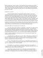
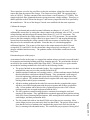
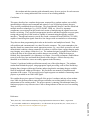
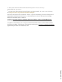
AC 2011-2532: AUTOMATED BATTERY CHARGER INSTRUMENTATION INTERFACE FOR MULTIPLE INTERCONNECTED BATTERY STRINGS AS A STUDENT PROJECT Herbert L. Hess, University of Idaho, Moscow Herbert L. ’Herb’ Hess received the PhD degree from the University of Wisconsin - Madison in 1993. He then joined the University of Idaho where he is Professor of Electrical Engineering. His work is in power electronic converters, great and small, alternative energy systems, power quality, energy storage electronics, and on-chip designs of energy management systems. In ASEE, he is currently Program Chair of the Instrumentation Division and is immediate past chair of the ECE Division and a past chair of the ECC Division. Page 22.269.1 c American Society for Engineering Education, 2011 Automated Battery Charger Instrumentation Interface for Multiple Interconnected Battery Strings as a Student Project Abstract The goal of this project was to create a remote monitoring and control capability for the eight large battery charging units currently in use at the Naval Acoustic Research Detachment in Bayview, Idaho. These units charge 1866 valve regulated lead acid batteries that provide power for propulsion, instrumentation, and control of the second Large Scale Vehicle (LSV 2), a Navy acoustic research submarine. These batteries must be charged while the submarine is dry docked with each of eight battery groups connected to its own independent charging unit. Charging consumes up to eighteen hours and requires constant monitoring by a battery technician. To allow for increased control of the inputs, students designed a remote control capability utilizing an incumbent government-approved, but unused and poorly documented, hardware interface within the chargers. The students verified data collection from existing sensors and formatted it within the charger’s architecture. They then transmitted the data to a computer workstation and stored and displayed it in a nearby office area. They implemented a government-approved algorithm to generate input commands for the chargers through their custom-designed graphical user interface. RS-232 serial communications presented these commands to the charger for automatic implementation. As required, a human operator verified the loop, comparing commands to resulting voltage and current readings. Initial testing of the prototype showed communications were established with Charger #1. Subsequent designs, accomplished as a follow-on project for a graduate student, completed the interface for the remaining chargers. This paper describes the design process, including both hardware and software design, as well implementation and testing, performance results, and recommendations for further improvement. Introduction Page 22.269.2 The US Navy operates an experimental quarter-scale submarine to test new concepts in naval architecture. This submarine is an all-electric ship, run by a six-phase synchronous motor. Nominal operating voltage is 720V DC, supplied from seven parallel strings of sixty lead-acid batteries each. These batteries must be charged, a process that takes from eight to eighteen hours. Each charger supplies energy to one of the strings of batteries. The incumbent system required an operator to manually configure, start, monitor, and manage each of the chargers individually. Previous efforts to interface to the chargers’ internal digital interface had failed. The project assigned to a senior undergraduate design team was to investigate the digital interface and design a software configuration that would communicate with it. The students were tasked to collect data from each charger, e.g., voltage, current, power, energy history, and temperature. Such data should be communicated to a desktop computer and displayed with a graphical user interface of the students’ design. From there, commands from the charging algorithm and from a human operator should be returned to the charger, implemented, and, using the same data collection system, verified at the operator’s console. Background The goal of this project is to develop an improved charging system for the electric Large Scale Vehicle (LSV) housed at the Naval Surface Warfare Center, Carderock Division (NSWCCD) at the Acoustic Research Detachment in Bayview, Idaho. This project was given to a senior design research team because “the University of Idaho and the NSWCCD seek to collaborate for the purpose of capitalizing on unique capabilities in intelligent systems development, autonomous vehicle control, power electronics, and advanced signal and data processing techniques.”1 The intent of the project is to support the operational needs of the NSWCCD; particularly addressing the charging requirements of this electric vehicle. The LSV2 USS Cutthroat, a follow-on-project from the first variation of a large-scale submersible vehicle the USS Kokanee, is the largest autonomous submarine in the world. The USS Cutthroat serves as a research and development platform for the United States Navy. The LSV2 is a completely autonomous 205 ton, 0.294-scale version of the Virginia Class submarine that utilizes an electric motor capable of producing up to 6000HP. A large bank of lead acid batteries mounted in the bow, or front compartment, of the boat supplies the power for this motor. This battery bank must be charged prior to each use with the charging process taking between eight and eighteen hours. A battery technician must remain on site throughout the charging process making necessary adjustments and monitoring voltage and current levels. A previous research team from the University of Idaho undertook the task of optimizing the charging profile to maintain the reliability of the lead acid batteries increasing their life span dramatically. Currently, these profiles must be manually monitored requiring that the technician verify the outputs on the front panel of the charging units and making adjustments as necessary. Incumbent system Presently, a battery technician utilizes a watch screen on a desktop computer to display the voltage and current levels being fed into the seven battery strings comprising the bank, and the single auxiliary charger. Upon encountering a condition requiring action, the technician must leave the computer workstation, walk out to a different location in the dry dock to reach the charging unit in question, and adjust analog knobs on its front. After the change has been set manually on the charging unit, the technician returns indoors to the workstation to verify that the desired effect has begun to take place. The technician repeats this process for each individual charging unit. The charging algorithm has predetermined set points during the charging process, each of which requires command changes and necessitates a new round trip as described above. This is not desirable because it introduces needless inaccuracy with the use of analog knob controls as well as delay and the loss of productivity from the commute between office and chargers. Proposed system Page 22.269.3 The proposed system allows the technician to monitor directly the charge via the computer workstation. The technician then commands adjustments, again from a computer workstation, without rising from the chair. Due to government contract restrictions, the proposed changes to the system must be add-ons for the current chargers, making no physical changes to units themselves. This adjustment interface contains an eight-port serial communications card with a custom (student-designed) graphical user interface (GUI) that controls the charging process of the seven propulsion chargers and the single auxiliary system charger. This addition of computer control of the chargers from the technician’s office streamlines the charging process, increases productivity, and allows for improved implementation of the charging algorithm with almost instantaneous command response from the charger outputs. Problem definition1 The charging profiles require several adjustments to both the voltage and current levels applied during a charging cycle. These charging profiles maximize the life of the lead acid batteries used on board the USS Cutthroat. Eight charging stations are connected to eight strings of batteries. The battery bank is separated into propulsion and auxiliary to facilitate servicing the power requirement of each system. The propulsion system battery bank is comprised of 1680, two-volt, valve regulated lead acid (VRLA) batteries connected in four parallel strings. The auxiliary battery bank, powering the test equipment and supporting apparatus, consists of 186, two-volt, VRLA batteries connected in a single string. After each LSV2 underway (operation), both the propulsion and auxiliary batteries require recharging. Throughout the charging process, voltage and current transitions are manually controlled on eight separate battery chargers by a battery-charging technician. A typical battery Figure 1. Interior of Charging Unit charge lasts between approximately eight and sixteen hours under expected load. The process requires close monitoring to maintain the appropriate current and voltage levels applied to the batteries. This process introduces human error to the charging algorithm for the LSV2’s battery bank. Once implemented, the proposed design will reduce the variations encountered using the present method. This will help to extend the lifecycle of the VRLA batteries used in the LSV2 as well as provide the maximum amount of stored charge for the performance of each test run. Criteria for successful completion1 Page 22.269.4 The team’s objective is to investigate and design a remote control for the LSV2 charging system. The Navy research team requires that the current charging system remain unaltered because it works. It has also passed the lengthy technical approval process as agreed between the builder and the Navy. The Navy desires only an improvement shell, not a redesign or modification of the incumbent system. Our improved design adds to the current system to accomplish our specific goals. The control system must have the ability to adjust the level of current and voltage supplied to the battery banks. Additionally, the control system must be able to display the front panel indicators of each of the eight charging units including: unit power, over voltage, over current, fan loss, over temperature, ground fault, and the current/voltage magnitudes. The controls on the front panel include adjustment knobs for voltage and current, and buttons for stop, start, and fault reset. The goal is to achieve remote manipulation of all of these controls. Specifications The primary goal of the research team is remote monitoring and control of all eight of the chargers. The charging units, manufactured by PTCI, have a remote/local stitch on the front panel connected to an ICS Electronics Corporation Model 2361 serial interface circuit board (Figure 1)2. The desired method of interaction with the chargers is to use this card, attaching external control to the serial interface circuitry installed via the J4 jack, 0.001-inch center pin connector. The interface card is mounted on the interior of the front panel and is easily accessible for the installation of the connecting cables. The ICS interface card is version 5 and has modifications that allow it to Figure 2. ICS 2361 Serial Interface Board be powered through the main connection header (J2). The required power for the card is +12V (volts) unregulated at J2 on pins 17, 39, and 60 with ground connected to pins 16, 38, and 59. These power connections are already made in the charging unit. The J2 header is wired to control the charging unit and is connected per the manufacturer’s design. A graphical user interface (GUI, pronounced “gooey”) is the chosen method for the battery technician to control the system. A GUI will enable the technician to communicate with the ICS board by entering desired values into preprogrammed fields, making it unnecessary for the technician to have programming knowledge. This will eliminate the need for additional training of the technician (e.g., to use a command line interface) as well as increase the speed of the commands as a program can communicate faster than human response times. Page 22.269.5 Front panel indications will be retrievable through the ICS card and displayed via the GUI. The primary use of the front panel indicators is to alert the battery technician of a fault condition. These indications must be checked and polled frequently, to assure their accuracy at the computer terminal display. The terminal emulation will send the check commands at regular intervals, every five to thirty seconds, to check these fault indicators. These intervals will be kept as short as possible. Design development restrictions The Navy requires the charging units remain unaltered from their original, functioning state. Any hardware necessary for the functionality of the design either must be already installed, or added in such a way that it does not interfere with the physical charging process itself. The statement of work from Navy reads: “Any additional hardware needed to accomplish autonomous charger control must be able to be installed, mounted, and operated in concert with the existing LSV2 battery chargers and must interface with the existing LSV2 support barge powering and cooling systems.”1 Additionally, the computer system used to control the chargers is a secure machine, isolated from outside data sources to protect the classified nature of the USS Cutthroat; because of this, there is no available Internet connection. Therefore, all software, for both the GUI and the hardware drivers, must be fully contained on a premade compact disc, which then installs and updates the system. Hardware design: Connection to charger control cards The ICS interface card has an RS232/RS-485 connection at J4; connecting the following three wires achieves this connection: transmit data output (Tx), receive data input (Rx), and signal ground (GND). The ten-pin header located at J4 uses the following pin assignments for connecting these wires in a RS232 configuration: Tx = pin 3, Rx = 2, and Figure 3. Wire Connections from Computer GND = pin 7 or pin 9. The signal ground is a to ICS Board very important component of serial communications as it is the baseline for all high and low determinations of signals. Therefore, it is necessary to take additional precautions to reduce the amount of electrically coupled noise by connecting wire shielding to a single ground point, eliminating ground-loop interference. Hardware design: Interconnecting Cables The connection made between the computer workstation and the charger’s interface card raises specific concerns including shielding, cross talk, and length restrictions that need to be addressed. The communication cabling environment is electromagnetically noisy due to the magnetic flux generated by the chargers’ large transformers. When these transformers step voltages to the appropriate levels during a charge cycle, they generate magnetic flux that can induce undesired voltages and currents. Magnetically coupled interference is very difficult to protect against; the proposed design uses twisted communication wiring to effectively cancel out electromagnetic interference (EMI) from external sources.3 Page 22.269.6 The possible conflicts with the communications via electromagnetic wave interference imposes constraints on cable length. The length of the cable connecting the parts of the system begins to have a deleterious effect when it exceeds approximately 100 feet. The lengths required for this project range from 20 to 40ft, well within the length allowed. This restriction must be contained in all installation and maintenance instructions in order to avoid system failure due to this kind of electromagnetic interference (EMI) problem. Software design The graphical user interface (GUI) is a key part of this project because it is the point where the battery technician remotely interfaces with the chargers. There are two aspects necessary for this interface to be successful: ease of monitoring and ease of making adjustments. The chargers’ front panel controls include three buttons (Start, Stop, and Fault Reset) and two knobs controlling voltage and current. An accompanying display shows a digital seven-segment LED readout. The design implemented these controls and display into the software for ease of use and familiarity for the technician. The GUI also provides fault. Figure 4. MOXA CP-118EL, 8 Port Serial Communication Card Computer communications interface card Page 22.269.7 A MOXA CP-118EL card is the serial networking interface card is installed in the PC to talk with the ICS cards. The product requires a computer workstation with an Figure 5. Wiring Diagram of System available PCI express slot on the motherboard for installation. Once connected, the switches must be set to select RS- 232. This changes the output pins and the output level range of the signal from the card. This product offers eight RS232, optically isolated communication lines, allowing each individual charger to have its own COM port. The terminal emulation program, PComm Lite, included with the MOXA card, allowed us to interface with the serial connection to send preprogrammed SCPI commands to the ICS boards. MOXA PComm Lite provided an alternative to using Microsoft's more complex Win32 COMM API; this added flexibility when designing and interfacing the GUI with the system. Wire and connectors To ensure the highest quality signal was achieved during communication, a premade and shielded cable was used. Using standard DB-9 cable connectors allowed for an easy connection with the MOXA card that has eight DB-9 male headers corresponding to each of the available COM ports. It was then determined using an ohmmeter, which wires corresponded to the appropriate pins in the MOXA connection. A ten-pin header was then attached to the opposite end ensuring these individual wires were properly positioned to connect with the proper pins of the ICS board. Removing all unused wires from the ten-pin header was a precaution to reduce risk of noise. These extra wires were secured using heat shrink on the exterior of the cable. All cables were constructed fifty feet in length— omitting unnecessary connectors to prevent possible uneven attenuation of the signal. Figure 6: GUI Simple Format Graphical user interface (GUI) Figure 7: GUI Advance Mode Page 22.269.8 The GUI has the human factors of a battery technician in mind. It incorporates the same terminology and control settings currently available on the front of the charging units. The GUI, implemented as a .exe file developed using Microsoft Visual 160 25 140 20 Volts 120 100 15 80 10 60 40 5 Voltage Out 20 Current Out 0 0 0 1 2 3 4 5 Input Voltage (Volts) 160 30 140 25 120 20 Volts 100 80 15 60 Amps Result of hardware testing 30 180 Amps Studios, allows the user to enter a desired value into a labeled block as a simple integer. The GUI then converts the desired inputs into Standard Commands for Programmable Instruments (SCPI), processed by the ICS cards inside of the chargers. The GUI makes it easier for users of all levels to control the chargers accurately. Its terminal mode, when open, allows the user to type in and send direct SCPI commands to the chargers. The standard mode, a programming interface, performs the same conversion for the user also. We designed the GUI for two different formats for entering commands: a simple format to send the same desired outputs to all chargers simultaneously (Figure 6), and an advanced format to make desired changes to a single charger at a time (Figure 7). The GUI contains all controls and indicators that are available on the front of all the chargers. The GUI allows for increased efficiency by sending out the required sequence of commands necessary to accomplish certain tasks in milliseconds instead of the order of seconds that humans can achieve. 10 40 20 Voltage Out 5 Current Out 0 Page 22.269.9 0 The hardware design and 0 0.2 0.4 0.6 0.8 setup was tested using charger #1 as a base. These test results Input Current (Amps) were then used to create the GUI, and provided a basis for the proper scaling of entries for Figure 8. Calibration curves: Voltage and current response mapping inputs to outputs. See to respective voltage and current inputs Figure 8. This test, conducted on the Navy site at Bayview, Idaho, and following a specific test plan, verified that the ICS board connected to the MOXA card controlled the charger in response to the proper SCPI commands. The data obtained was the output voltage and current of the charger with respect to the input voltage and currents applied. These responses enabled computing a slope that could convert and calibrate the input integers to necessary SCPI values. Software test, version 1.0 After the completion of the GUI, the software design was tested to verify correct operation and functionality between the GUI and the charging units. Once again, charger #1 performed the initial solo charger testing. This test was successful: the outputs entered into the GUI were correctly sent and implemented by the charger. However, these results could not be replicated on the other chargers, and it could not be determined if the GUI could accurately control multiple charges at once. While not able to set the outputs of chargers, other than Charger #1, the GUI was able to establish communications with all the chargers, and perform the basic start up and initialization procedure. After this initialization procedure, all commands to alter the outputs were received incorrectly by the chargers. The values entered into the GUI were not the values being sent to the chargers and use of the command prompt line showed the inaccuracies of what the GUI was showing and the values being read into the individual chargers. Revisions to address the incomplete success of version 1.0 At the 2008 ASEE Annual Conference in Pittsburgh, we presented a successful model for organizing and teaching students using large, daunting projects like this. 5 This model again proved successful in enabling completion of this project on time and within budget. A team of three undergraduates, under the supervision of a professor and one graduate student, designed the system during academic year 2009 - 2010. The graduate student mentored the undergraduates and then assumed responsibility for finishing the project. He solved the shortcomings of the project as described as follows. An important discovery after the test was that a delay of 100ms between commands was not always long enough to allow the ICS board time to process a command before receiving a new one. The delay was set to 250ms to compensate for this. This delay change resolved the problem of commands not realizing on the charger. Accuracy of data appeared to be a problem as well. Analog data was normalized to a 05V scale. Testing revealed an output reading from the charger by the ICS board could deviate by up to 0.2V. This large an error was not acceptable In an attempt to overcome the error in reading the output, the GUI was modified to average five consecutive readings of the output for display. Though this reduced the error, it was still insufficiently accurate and unacceptably imprecise. Page 22.269.10 Output voltage readings of charger #1 were significantly more repeatable and more accurate than readings from the other seven chargers. Comparing the ICS board in charger #1 with charger #7 revealed that two capacitors, labeled C82 and C83 were missing on charger #7. These capacitors served as low pass filters on the plus and minus voltage lines that collected sensor data from the output of the charger. The resistor used was 1KΩ. The capacitors had a value of 0.022µF. The time constant of this circuit forms a cutoff frequency of 7.23MHz. This simple single pole filter eliminated the noise causing inaccurate voltage readings. Therefore, we added capacitors to the ICS board in charger #7 and accuracy improved to the level specified by the manufacturer. The rest of the chargers’ boards were modified with the same capacitors. Calibrate the chargers We performed and recorded a manual calibration on chargers #1, #2, and #7. We calibrated the current first, by setting the voltage control to the maximum value of 5.0V, to avoid voltage limiting, and then step up the current control from 0-5V, in 0.25V increments. The process was repeated as the voltage stepped down, also in 0.25V increments. We repeated the process, this time setting the voltage control to its upper limit of 5V and stepping through the current, then decrementing the voltage control for the next sequence of current steps, etc. The data proved to be consistent and repeatable. From this data, we calculated appropriate calibration functions. The accuracy of the input to the output measured on the ICS board averaged 98.53% and 99.02% for the current and voltage respectively on charger #1; other chargers exhibited similar accuracy. The graduate student verified these results on site at the Navy base. Educational aspects of this project Page 22.269.11 As mentioned earlier in this paper, we engaged the students using a previously successful model for organizing and teaching students using large, daunting projects. We presented the details of our model in our award-winning ASEE paper from 2008. 5 For this project, we again consider our method of teaching students to be successful for the following reasons: The project finished on time and under budget. Navy engineers and contractors who had attempted the same project in the past did not finish at all. Student anecdotal comments were strongly positive. All three students returned feedback that described their satisfaction with their learning. They encountered a wide range of electrical engineering problems and solved each successfully to the satisfaction of the project’s sponsor. The students identified and recognized this wide range of successful learning in their end-of-project comments. All three students graduated at the end of the semester that they completed the project. All three were offered employment with the project sponsor and all three accepted the offer. Of ten students who worked on Navy-sponsored projects since 2007 with our teaching model, nine accepted employment with the Navy The Navy sponsors returned strongly positive comments concerning the work and learning of the students. They applauded their organized approach, their problem-solving skills, their focused learning and performance, their meeting the deliverables on time and under budget, and their presentation skills. The Navy made bids with no less than $25,000 each of the next two semesters. Most senior design projects at our university draw less than $5000. The project officer made it clear that the success of students who completed this project had a lot to do with the Navy’s returning with substantial money. We consider the project sponsor’s hiring all of the students and then returning with substantial money for new projects for each semester since to be a strong indication of the success of our teaching methods. Conclusions This paper describes how a student design team, mentored by a graduate student, successfully automated data collection and command and control of a set of eight large battery chargers. They carefully established the specifications. They found that the chargers’ interface board had multiple interface technologies, e.g., RS232, RS485, GPIB, etc. However, important components were missing from the boards and a means of multiplexing the signals from seven boards was lacking. They specified an appropriate interface and then bought the necessary parts, testing and proving the revised boards as capable of communicating through the available interfaces. Through and extensive search, they found a commercial board (MOXA CP-118EL) capable of interfacing that signals from the seven chargers with no translation or reformatting. They then set about programming their tasks on the interface and multiplexer boards. They collected data and communicated it to a data file on the computer. They sent commands to the interface board in a manner that caused appropriate actions, e.g., start, check system for safe and defined initial condition, change parameters to conform to a desired state, engage charging mode, stop charging, set or change current level, etc. The students designed a graphical user interface to show the state of the system and to enable changes conveniently. When the design was finished, they demonstrated it in a laboratory on campus. Successful performance enabled them to travel to the Navy base and install their boards on the chargers. On their first trip, they identified several interface issues not readily apparent in the laboratory. Version 1.0 performed within specifications on only one of the eight chargers. The graduate student then finished the project, using appropriate signal processing, such as filters and delays, bringing three chargers within specifications and proving that the remaining chargers could be likewise multiplexed within specifications. We provided a user manual for installation and operation of the system. This successful project again supports our methods of mentoring senior projects as presented in our 2008 ASEE paper. We consider the projects sponsor’s hiring all of the project’s students (and nine of ten students since 2008 who performed their senior design work under our teaching model) to be a strong endorsement of our teaching model. The project sponsor’s returning with substantial money to fund more projects every semester since is also a strong indicator of the success of our teaching method. References 1 “ICS 2361A RS-232/RS-485 to Analog Interface,” ICS Electronics div Systems West, Inc., ©2010, access 17 January 2011, http://www.icselect.com/pdfs/2361A_ds.pdf. Page 22.269.12 2 Klein, James M., “LSV2 Autonomous Battery Charge Implementation Statement of Work”, August 2009. 3 S. Wolf, Guide to Electronic Measurements and Laboratory Practice. 2nd ed., New Jersey: Prentice-Hall, 1983, pp. 387–412. 4 “CP-118EL 8-port RS-232/422/485 smart PCI Express serial board,” MOXA, Inc., ©2011, access 17 January 2011, http://www.moxa.com/product/download/CP-118EL.pdf. 5 Klein, James M., Herbert L.Hess, and Brian K. Johnson, “Cooperative Methodology for Successful Integration of Undergraduate and Graduate Research Projects,” 2008 ASEE Annual Conference and Exposition, Pittsburgh, Pennsylvania, June 2008, Paper AC-2008-114. 6 Axelson, Jan. Serial Port Complete: COM Ports, USB Virtual COM Ports, and Ports for Embedded Systems. Second. Madison: Lakeview Research LLC, 2007. 7 Georg Becke, Christian Borgert, Steve Corrigan, Frank Dehmelt, Matthias Feulner, Carmen Gonzalez, Michael Groenebaum, Firoj Kabir, Arek Kacprzak, Clark Kinnaird, Johann Zipperer. SLLA067A: Comparing Bus Solutions. Application Report. Dallas: Texas Instruments, 2004. Page 22.269.13