1
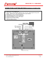
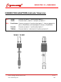
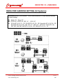
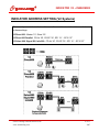
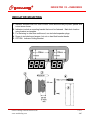
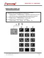
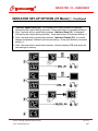
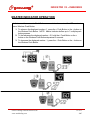
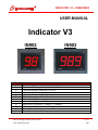
INDICATOR V3 ~ IN902/IN903 USER MANUAL Indicator V3 IN902 Page # 2 3 4 5 6 7 8 9 10 11 12 13 IN903 USER MANUAL CONTENTS: Product Configurations Connections & Setting-Switches (On Back Of Indicator) Connection Adapters (Indicator V2service) Indicator Address Setting (V3 Systems) Indicator Address Setting (V2 Systems) Indicator Mounting Indicator Start-Up Indicator Set-Up Options (V3 Master) Indicator Set-Up Options (V3 Master) ~ Continued Indicator Sound Tone & Volume Settings Master Indicator Operation Turn-O-Matic Contact Information SATO Labeling Solutions America, Inc. www.satolabeling.com 1 of 13 2007 INDICATOR V3 ~ IN902/IN903 PRODUCT CONFIGURATIONS 1. 2. 3. 4. 5. 6. 7. 8. Indicator Module V3, IN902M Indicator Module V3, IN903M Indicator V3, IN902 Indicator V3, IN903 Indicator Pack V3, IN902 PB Indicator Pack V3, IN902 RF Indicator Pack V2service, IN902 Indicator Pack V2service, IN903 SATO Labeling Solutions America, Inc. www.satolabeling.com 2 of 13 2007 INDICATOR V3 ~ IN902/IN903 CONNECTIONS & SETTING-SWITCHES (ON BACK OF INDICATOR) 1. Data In/Out, RJ10 modular plug 2. Power In/Out, 2.5mm DC plug. Maximum 5m (16-1/2 ft.) cable length in from power supply. Maximum 1m (3 ft.) cable length Out to next Indicator. 3. Push Buttons (- and +), RJ10 modular plug 4. Cascade display In/Out, RJ10 modular plug 5. Wireless Push Button receiver, IDC-10 pin 6. Sound tone and volume setting 7. TOM-Net address setting SATO Labeling Solutions America, Inc. www.satolabeling.com 3 of 13 2007 INDICATOR V3 ~ IN902/IN903 CONNECTION ADAPTERS (Indicator V2service) DC ~ 12VAC: 15VDC: RJ ~ Connect one lead to 1, and the other lead to 2 Connect minus (-) lead to 1, and plus (+) lead to 2 Push Button: Connect one lead to 2, and the other lead to 3. Use one adapter for plus (+) Push Button, and one adapter for minus (-) Push Button. Cascade: Connect one lead to 1, and the other lead to 2 TOM-Net: Connect shield to 1, white lead to 2 and brown lead to 3 12VAC / 15 VDC 1 2 SATO Labeling Solutions America, Inc. www.satolabeling.com 123 4 of 13 2007 INDICATOR V3 ~ IN902/IN903 INDICATOR ADDRESS SETTING (V3 Systems) Disconnect power to the Indicator. Use a small screwdriver to rotate address switches to these settings: S3 Master ‘51’, Slave ‘50’ M3 CD-Nr ‘50’, CD-SP ‘60’, SP1 ‘51’ … SP15 ‘5F’ L3 CD-Nr (ST A..E) ‘C1…C5’, CD-SP(ST A..E) ‘D1…D5’, Recall-Nr (ST A..E) ‘CA…CE’, Recall-SP (ST A..E) ‘DA…DE’, SP1 ‘51’…SP16 ‘61’…SP30 ‘6F’, HCW (ST A..E) ‘BA…BE’, HAP ‘B9’, AWT(ST A..E) ’3A…3E’, DSN (ST A..E) ’31…35’. SATO Labeling Solutions America, Inc. www.satolabeling.com 5 of 13 2007 INDICATOR V3 ~ IN902/IN903 INDICATOR ADDRESS SETTING (V2 Systems) Disconnect power to the Indicator. Use a small screwdriver to rotate address switches to these settings: V2 Direct 900: Master ’21’, Slave ‘20’ V2 Direct 900 Parallel: CD-Nr ‘20’, CD-SP ‘30’, SP1 ‘21’…SP15 ‘2F’ V2 Select 900, Signal 900, Info 900: CD-Nr ‘20’, CD-SP ‘30’, SP1 ‘21’…SP15 ‘2F’ SATO Labeling Solutions America, Inc. www.satolabeling.com 6 of 13 2007 INDICATOR V3 ~ IN902/IN903 INDICATOR MOUNTING 1. Indicator Modules click into 3mm or 6mm thick aluminum/acrylic plastic panels with cutout sizes shown 2. Indicators include a mounting bracket that must be fastened. Mark hole location using bracket as template. 3. For fastening in other than solid wood, use included expander plugs. 4. Screw in included wood screws, but not so hard that bracket bends. 5. OPTION: Indicator Ceiling Bracket SATO Labeling Solutions America, Inc. www.satolabeling.com 7 of 13 2007 INDICATOR V3 ~ IN902/IN903 INDICATOR START-UP 1. Plug power supply into a suitable mains outlet and into the indicator. 2. An Indicator set to a Master address (51 or 21) displays: Program Version … TOM-Net address … Last number displayed at power OFF (00 / 000 if first start). If duplicate Master (NOT allowed) ‘Ed’ is displayed. 3. An Indicator set to a non-Master address (50, 20, 30, C1 etc.) displays: Program Version … TOM-Net address … Bland screen. 4. An Indicator set to an invalid address (ex. 81) displays: Program Version … EA … address … EA … address … EA … SATO Labeling Solutions America, Inc. www.satolabeling.com 8 of 13 2007 INDICATOR V3 ~ IN902/IN903 INDICATOR SET-UP OPTIONS (V3 Master) 1. Connect a Push Button to the Push Button plus(+) port on the Indicator. Restart the Indicator by disconnecting and reconnecting power. Hold the Push button depressed during the Indicator start-up display sequence to enter the setup options. 2. Alternatively, for an Indicator pack with a Wireless Push Button, hold the plus (+) button on the Wireless Push Button depressed during the Indicator start-up sequence to enter the setup options. Continued on next page SATO Labeling Solutions America, Inc. www.satolabeling.com 9 of 13 2007 INDICATOR V3 ~ IN902/IN903 INDICATOR SET-UP OPTIONS (V3 Master) ~ Continued 3. ‘Indicator Update delay (UP)’ (on multiple push button presses) is displayed, followed by the current setting (seconds). Press push button to increment setting +1. 4. After 3 seconds with no push button presses, ‘Indicator Sleep (SL)’ is displayed, followed by the current setting (minutes). Press push button to increment setting +1. 5. After 3 seconds with no push button presses, ‘Indicator Flashes (FL)’ on number change is displayed, followed by the current setting. Press push button to increment setting +1. 6. After 3 seconds with no push button presses, Indicator displays ‘CS’ and saves the new settings to memory. SATO Labeling Solutions America, Inc. www.satolabeling.com 10 of 13 2007 INDICATOR V3 ~ IN902/IN903 INDICATOR SOUND TONE & VOLUME SETTINGS Use a small screwdriver to change switch settings: 1. Sound tone is set with switches 1-2: SW1-OFF, SW2-OFF = no sound (for 2 or more indicators in a cluster, set sound on for only one indicator) SW1-OFF, SW2-ON = single tone SW1-ON, SW2-OFF = double tone SW1-ON, SW2-ON = triple tone 2. Sound volume is set with switches 3-4: SW3-OFF, SW4-OFF = low volume SW3-ON, SW4-Off = medium volume (recommended for most installations) SW3-OFF, SW4-ON = high volume SATO Labeling Solutions America, Inc. www.satolabeling.com 11 of 13 2007 INDICATOR V3 ~ IN902/IN903 MASTER INDICATOR OPERATION Indicator must have + and – Push Buttons connected or have an installed RF receiver to use a Wireless Push Button: 1. To advance the displayed number +1, press the + Push Button or the + button on the Wireless Push Button. NOTE: Master Indicator buffers up to 7 multiple push button presses. 2. To fast advance the displayed number +10, hold the + Push Button or the + button on the Wireless Push Button depressed 3 seconds. 3. To decrease the displayed number -1, press the – Push Button or the – button on the Wireless Push Button. SATO Labeling Solutions America, Inc. www.satolabeling.com 12 of 13 2007 INDICATOR V3 ~ IN902/IN903 TURN-O-MATIC CONTACT INFORMATION: CUSTOMER SERVICE: Customer Service SATO LABELING SOLUTIONS AMERICA, INC. 1140 Windham Parkway Romeoville, IL 60446 Customer Service Toll Free Phone #: (800) 645-3290, Ext. 8 Customer Service Direct Phone #: (630) 771-4200, Ext. 8 Customer Service Fax #: (630) 771-4250 TECHNICAL CENTER: Technical Center SATO LABELING SOLUTIONS AMERICA, INC. 30 Chapin Road, Suite 1201 PO Box 777 Pine Brook, NJ 07058 Technical Center Toll Free Phone #: (800) 205-7611, Ext. 3654 Technical Center Direct Phone #: (973) 287-3654 Technical Center Fax #: (973) 227-3961 SATO Labeling Solutions America, Inc. www.satolabeling.com 13 of 13 2007