1
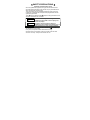
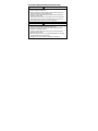
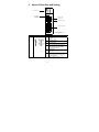
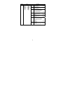
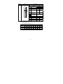
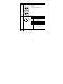
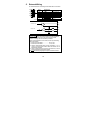
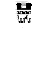
A1SJ71UC24-R4/A1SJ71C24-R4
Computer Link Module
MITSUBISHI
General-Purpose PROGRAMMABLE CONTROLLER
User's Manual
(Hardware)
Thank you for buying the Mitsubishi general-purpose
programmable controller MELSEC-A Series.
Prior to use, please read this manual thoroughly and
familiarize yourself with the product.
MODEL
A1SJ71C24-R4(H/W)U-E
MODEL
CODE
13JE52
IB(NA)-66491-D (0902) MEE
©1998 MITSUBISHI ELECTRIC CORPORATION
SAFETY PRECAUTIONS
(Read these precautions before using.)
When using Mitsubishi equipment, thoroughly read this manual and the
associated manuals introduced in the manual. Also pay careful attention to
safety and handle the module properly.
These precautions apply only to Mitsubishi equipment. Refer to the CPU
module user’s manual used for a description of the programmable controller
system safety precautions.
These SAFETY PRECAUTIONS classify the safety precautions into two
categories: "DANGER" and "CAUTION".
DANGER
CAUTION
Procedures which may lead to a dangerous
condition and cause death or serious injury if not
carried out properly.
Procedures which may lead to a dangerous
condition and cause superficial to medium injury, or
physical damage only, if not carried out properly.
Depending on circumstances, procedures indicated by
CAUTION may
also be linked to serious results.
In any case, it is important to follow the directions for usage.
Store this manual in a safe place so that you can take it out and read it
whenever necessary. Always forward it to the end user.
[DESIGN PRECAUTIONS]
DANGER
• When performing the control of the programmable controller in operation
(especially changing data, program and operation status (Remote
RUN/STOP)) by connecting a personal computer, etc. to the special
function module, configure an interlock circuit in a sequence program so
the safety of the overall system is always maintained.
Particularly in the above described control for a remote site programmable
controller from an external device, troubles occurring on the
programmable controller side may not be immediately handled due to a
data communication error. Construct an interlock circuit in the sequence
program and determine between the external device and programmable
controller CPU the system's error handling procedure and other items
regarding data communication errors.
CAUTION
• Do not bunch the control wires or communication cables with the main
circuit or power wires, or install them close to each other.
They should be installed 100 mm (3.9 inch) or more from each other.
Not doing so could result in noise that would cause malfunction.
[INSTALLATION PRECAUTIONS]
CAUTION
• Use the programmable controller in the environment given in the general
specifications section of the applicable User's Manual for the CPU module
used.
Using this programmable controller in an environment outside the range of
the general specifications could result in electric shock, fire, malfunction,
and damage to or deterioration of the product.
• Shut off the external power supply for the system in all phases before
wiring.
If you do not switch off the external power supply, it will cause electric
shock or damage to the product.
• Insert the tabs at the bottom of the module into the mounting holes in the
base module, and tighten the module installation screws with the specified
torque.
If the module is not properly installed it may result in malfunction, failure or
fallout.
• Tighten the screw within the range of specified torque.
If the screw are loose, it may result in fallout, short circuit or malfunction.
Tightening the screws too far may cause damage to the screw and /or the
module, resulting in fallout, short circuit or malfunction.
• Do not directly touch the module's conductive parts or electronic
components. Doing so could cause malfunction or failure in the module.
• Perform correct pressure-displacement, crimp-contact or soldering for wire
connections using the tools specified by the manufactures.
Attach connectors to the module securely.
[WIRING PRECAUTIONS]
CAUTION
• Be sure that the communication cable connected to the module is kept in
a duct or fixed with cramps.
Failure to do so may cause a damage to the module or cables due to
dangling, shifting or inadvertent handling of cables, or misoperation
because of bad cable contacts.
• Before connecting the cables, check the type of interface to be connected.
Connection, or erroneous wiring to the wrong interface may damage the
module and external device.
• When connecting an external device to RS-422 interface of this module,
do not connect a device that must receive power from this module.
The module or external device may be damaged.
• Tighten the terminal screw within the range of specified torque.
If the screws are loose it may result in short circuit or malfunction.
Tightening the screws too far may cause damage to the screw and/or the
module, resulting in fallout, short circuit or malfunction.
• Do not grab on the cable when removing the communication cable
connected to the module.
When removing the cable without connector, loose the screw on the side
that is connected to the module.
Pulling the cable that is still connected to the module may cause
malfunction or damage to the module or cable due to bad cable contacts.
• Be sure there are no foreign substances such as sawdust or wiring debris
inside the unit.
Such debris could cause fire, damage or malfunction.
[STARTING AND MAINTENANCE PRECAUTION]
DANGER
• Do not touch the terminals while the power is on.
Doing so may cause malfunction.
• Always switch OFF the external supply power used by the system in all
phases before cleaning or retightening screws.
If you do not switch off the external power supply, it will cause failure or
malfunction of the module.
If the screws are loose, it may result in fallout, short circuit or malfunction.
Tightening the screws too far may cause damage to the screws and/ or
the module, resulting in fallout, short circuit or malfunction.
CAUTION
• Do not diassemble or modify the modules.
Doing so could cause failure, malfunction, injury or fire.
• Shut off the external power supply for the system in all phases before
mounting or removing the module.
If you do not switch off the external power supply, it will cause failure or
malfunction of the module.
• Before handling the module, touch a grounded metal object to discharge
the static electricity from the human body.
Not doing so may cause a failure or malfunction of the module.
[OPERATION PRECAUTIONS]
DANGER
• Do not write data to the "system area" in the buffer memory of the special
function module.
Also, do not output (or turn on) a "use prohibited" signal from the
programmable controller CPU to the special function module. If data is
written to the "system area" or if the "use prohibited" signal is output, there
is a risk that the programmable controller system will operate incorrectly.
CAUTION
• Before performing the control of the programmable controller in
operation(especially changing data, program and operation status(Remote
RUN/STOP)) by connecting a personal computer, etc. to the special
function module, read User's Manual (Com. link func. /Print. func.)
carefully and confirm if the overall safety is maintained.
Failure to perform correct operations to change data, program or the
status may result in system malfunction, machine damage or an accident.
[DISPOSAL PRECAUTIONS]
CAUTION
• When disposing the product, treat it as industrial waste.
About Manuals
The following product manuals are available. Please use this table as a
reference to request the appropriate manual as necessary.
Related Manuals
Manual No.
(Model Code)
Manual Names
Computer Link Module Guide Book
SH-3510
(13JE76)
Computer Link Module (Com. link func. /Print. func.)
User’s Manual
SH-3511
(13JE77)
When using this module, be sure to read Computer Link Module User's
Manual (Com. link func. /Print. func.) as well as this manual.
A1SJ71UC24-R4 computer link function is the same as AJ71UC24.
When you refer to the following manual to use A1SJ71UC24-R4, replace
the module model name to refer.
Computer Link Module User's Manual (Com. link func. /Print. func.)
...................................... Version C or before
AJ71UC24 → A1SJ71UC24-R4
Conformation to the EMC Directive and Low Voltage Instruction
For details on making Mitsubishi programmable controller conform to the
EMC directive and low voltage instruction when installing it in your
product, please see Chapter 3, "EMC Directive and Low Voltage
Instruction" of the User's Manual (Hardware) of the programmable
controller CPU to use.
The CE logo is printed on the rating plate on the main body of the
programmable controller that conforms to the EMC directive and low
voltage instruction.
By making this product conform to the EMC directive and low voltage
instruction, it is not necessary to make those steps individually.
1. Overview
This manual is intended for installing the computer link module and
performing wiring for external devices.
After unpacking the module, check that the following products are
included:
Model name
A1SJ71UC24-R4
A1SJ71C24-R4
Item name
A1SJ71UC24-R4 computer link module
Terminal resistor for RS-422 communication
330 Ω 1/4 W (orange-orange-brown )
Terminal resistor for RS-485 communication
110 Ω 1/2 W (brown-brown-brown )
A1SJ71C24-R4 computer link module
Terminal resistor for RS-422 communication
330 Ω 1/4 W (orange-orange-brown )
Terminal resistor for RS-485 communication
110 Ω 1/2 W (brown-brown-brown )
Quantity
1
2
2
1
2
2
* In the explanation hereafter, the computer link/multi-drop link module is
abbreviated as the "C24" except when differentiate specially.
* The following accesses to the programmable controller CPU with a
dedicated protocol of the computer link function are possible by using
A1SJ71UC24-R4.
Access to the device extended by AnACPU, AnUCPU and
A2US(H)CPU.
Access to the other stations via MELSECNET/10.
Other specifications are the same as A1SJ71C24-R4.
* Differentiate the terminal resistors as follows:
330Ω
Orange Orange Brown
110Ω
1
Brown
Brown
Brown
2. Transmission Specifications
The following table indicates the transmission specifications when using
the C24 computer link function.
For general specifications of the UC24, see the user's manual for the
CPU module used.
Item
Interface
Transmission method
Specification
Conform to RS-422/485
Dedicated protocol Half duplex communication method *1
No protocol/
1:1
Full duplex
connection communication method
Bidirectional
1 : n, m : n
connection
Synchronization system
Transmission speed
Data
format
Start bit
Data bit
Parity bit
Stop bit
Access cycle
Error detection
DTR/DSR control
(ER/DR)
DC1/DC3, DC2/DC4
control
Line configuration
(external device:
programmable
controller CPU)
Transmission distance
Current consumption
Occupied I/O points
Weight
Half duplex
communication method
Start-stop synchronization method
300, 600, 1200, 2400, 4800, 9600, 19200 bps
(Selected via the switch)
1
7 or 8
Selected via the switch
1 or none
1 or 2
Processing for one request is performed during the END
processing of the sequence program. Therefore, the
access cycle is one scan time.
Parity check yes (odd/even) or no
Sum check yes or no
No
Yes/No (selected by setting to the buffer memory)
Dedicated protocol
No protocol
1 : 1, 1 : n, m : n
1 : 1, 1 : n
Bidirectional
1:1
RS-422/485 Overall distance 500m (1640 ft.) or less
5VDC 0.1A
32 points *2
0.25 kg(0.56 lb.)
*1 When data communication can be performed using the full duplex
transmission method, this transmission method is used whenever
the on-demand function is used.
*2 When performing I/O assignment using the GPP function, set as
special 32 points.
The model name to register when using the dedicated commands,
the following model name should be set depending on C24 and
programmable controller CPU mounted to C24.
2
Programmable
Types of C24 to mount
controller CPU
mounted to C24
A1SJ71UC24-R4
A1SJ71C24-R4
AnUCPU
A1SJ71UC24
AJ71C24S3
AnACPU
AJ71C24S3
Other than AnU/AnACPU (Model name setting is not necessary as the dedicated
command cannot be used.)
3
3. Name of Each Part and Setting
A1SJ71C24-R4
1) Indicator LED's
MD
SW
01
02
ST.DWN
MD L
STATION NO.
03
04
01
456
78
9
2) Transmission
specification
setting switch
SCAN
SET E.
SCAN E.
SIO E.
NEU
ACK
NAK
C/N
P/S
PRO
SIO
COM
10
23
05
06
01
456
9
78
07
08
1
3) Station number
setting switch
23
09
10
11
89
67
012
12
EF
CD
AB
MODE
4) Mode setting switch
345
SDA
SG
SDB
FG
6) RS-422/485 interface
RDA
NC
RDB
RS-422/485
A1SJ71C24-R4
Number
Name
1)
Indicator LEDs
RUN
SD
RD
CPU
MD
NEU
ACK
NAK
C/N
P/S
PRO
SIO
COM
RUN
SCAN
SET E.
SCAN E.
SIO E.
ST.DWN
MD L
SD
RD
CPU
MD
NEU
4
* The module diagram is shown
with A1SJ71C24-R4.
Description
Normal operation indicator
Normal : lit
Error
: unlit
Transmission status
Data being transmitted
: flashing
Reception status
Data being received
: flashing
Communication Status with CPU main
module.
Communicating with programmable
controller CPU : flashing
Multi-droplink
Multi-droplink
: lit
Computer link : unit
Neutral status
Transmission sequence initial status
(waiting for ENQ)
: lit
ENQ reception complete : unlit
Number
1)
Name
Indicator LEDs (continued)
RUN
SD
RD
CPU
MD
NEU
ACK
NAK
C/N
P/S
PRO
SIO
COM
SCAN
SET E.
SCAN E.
SIO E.
ACK
NAK
ST.DWN
MD L
C/N
P/S
PRO
SIO
COM
5
Description
ACK transmission status
ACK transmitted
NAK transmitted
NAK transmission status
NAK transmitted
ACK transmitted
Result of communication with
programmable controller CPU
Error in communication with the
programmable controller CPU
Normal communication
Parity/sum check error
Parity/sum check error
Normal
Protocol error
Normal protocol error
Normal
SIO error
When overrun or framing error
When received data has been
discarded due to OS receive
area full
Normal
Computer link
Computer link or multi-drop link
(local station)
Multi-drop link (master station)
: lit
: unlit
: lit
: unlit
: lit
: unlit
: lit
: unlit
: lit
: unlit
: lit
: lit
: unlit
: lit
: unlit
Number
Name
2)
Transmission setting switch
SW
01
02
03
04
ON
ON
05
06
07
08
09
10
11
12
Description
Transmission settings (all are set to OFF at the time
of shipment)
SW
Setting item
Status
ON
OFF
01
Not used
⎯
⎯
Computer link/multi- Computer Setting
02
drop link selection
impossible
link
03
A1ADP-SP setting A1ADP- A1ADP*1
SP used
SP not
used
04
Setting for write
Enabled Disabled
during RUN
05
Transmission
06
speed setting
See *2
07
08
Data bit setting
8 bits
7 bits
09
Parity bit setting
YES
NO
10
Even/odd parity
Even
Odd
setting
11
Stop bit setting
2 bits
1 bit
12
Sum check setting
YES
NO
*1
This setting is available when software version of the
A1SJ71UC24-R4 is X or later, and not available for the
A1SJ71C24-R4.
*2
Transmission speed settings
Setting switch
300
600
SW05
SW06
SW07
OFF
OFF
OFF
ON
OFF
OFF
Transmission speed (unit: bps)
1200 2400 4800 9600 19200
OFF
ON
OFF
6
ON
ON
OFF
OFF
OFF
ON
ON
OFF
ON
OFF
ON
ON
Setting
prohibited
ON
ON
ON
Number
Name
3)
Station number setting
switch
7 8
0 1
4 5 6
9
×10
Description
Module station number setting (set to 00 at time of
shipment)
<Setting range>
00 to 31
X10 --- set the station number ten's place
X1 --- set the station number unit's place
2 3
7 8
0 1
4 5 6
9
×1
2 3
Mode setting switch
012
67
A
BCD
EF
89
4)
MODE
Mode setting (set to 0 at the time of shipment)
Mode
Setting contents
0
Use prohibited
1
to
Use prohibited
3
4
Non procedure mode
5
Type 1 dedicated protocol mode
6
Type 2 dedicated protocol mode
7
Type 3 dedicated protocol mode
8
Type 4 dedicated protocol mode
345
9
to
Use prohibited
E
5)
RS-422/485 interface
F
For module test
RS-422/485 interface for external device connection
7
4. Loading and Installation
This section explains precautionary items regarding handling of the C24
from unpacking up to installation, and the installation environment that are
common to all modules.
See the user's manual for the programmable controller CPU module
used for further details regarding module loading and installation.
4.1
Precautionary Items when Handling
The following explains precautionary items when handling the module:
(1) Do not drop or apply severe shock to the module case since it is
made of resin.
(2) Tighten the module installation screws within the specified torque
range as follows:
Screw Area
RS-422 / 485 terminal block terminal screws
(M3.5 screw)
Module installation screws (M4 screw)
Tightening Torque Range
59 to 88N • cm
(5.2 to 7.8lb • inch)
78 to 118N • cm
(6.9 to 10.4lb • inch)
RS-422 / 485 terminal block installation screws 49 to 78N • cm
(M3.5 screw)
(4.3 to 6.9lb • inch)
8
4.2
Installation Environment
Avoid the following conditions for the installing location of the AnS Series
programmable controller:
(1) Location where the ambient temperature exceeds the range of 0 to
55 °C.
(2) Location where the ambient humidity exceeds the range of 10 to
90% RH.
(3) Location where condensation occurs due to a sudden temperature
change.
(4) Location where corrosive or inflammable gas exists.
(5) Location where a lot of conductive powdery substance such as dust
and iron filing, oil mist, salt, or organic solvent exists.
(6) Location exposed to direct sunlight.
(7) Location where strong electric fields or magnetic fields form.
(8) Location where vibration or impact is directly applied to the main
module.
9
5. External Wiring
The standard method for connecting the RS-422/485 line is shown below:
SDA
SG
SDB
RDA
NC
RDB
Signal
Signal direction
External device
abbreviation C24
SDA
SDB
RDA
RDB
SG
FG
NC
Description
Transmission data
Transmission data
Reception data
Reception data
Signal ground
Frame ground
Vacancy
(Function block diagram for the C24)
SDA
+
Transmission data
–
SDB
+
RDA
–
RDB
Reception data
Point
If the C24 serves as the first or the last station on the RS-422/485 line,
connect a terminal resistor as shown below to the RS-422/485
interface according to the communication specification.
When a terminal resistor is not connected, an error may result during
data communication.
• For RS-422 communication ...................... 330 Ω, 1/4W
• For RS-485 communication ...................... 110 Ω, 1/2W
(1) When an external device and the C24 are connected in 1:1 or 1:n,
connect a terminal resistor between SDA and SDB as well as
between RDA and RDB.
(2) When an external device and C24 are connected in m:n, connect
a terminal resistor between RDA and RDB.
The R in the following wiring diagram represents a terminal resistor.
10
(1) Example of connecting external devices and C24 by 1:1
External device
Signal name
RDA
RDB
SDA
SDB
RSA
RSB
CSA
CSB
R
R
Cable connection and
signal direction (example)
C24
Signal name
SDA
SDB
RDA
RDB
R
R
NC
SG
FG
SG
FG
(2) Example of connecting external devices and C24 by 1:n
* Connecting external devices and C24 modules via RS-485
External
device
R
R
RS-485
RS-485
Station 0 C24
RS-485
Station 1 C24
Station n C24
SDA
SDA
SDA
SDB
SDB
SDB
SDB
RDA
RDA
RDA
RDA
SDA
RDB
RDB
RDB
RDB
SG
SG
SG
SG
FG
FG
FG
FG
R
R
(3) Example of connecting external devices and C24 by m:n
* Connecting external devices and C24 modules via RS-485
External
device
External
device
SDA
SDB
RDA
RDB
SG
FG
SDA
SDB
RDA
RDB
SG
FG
Station 0
C24
Station 1
C24
Station n
C24
SDA
SDB
RDA
RDB
SG
FG
SDA
SDB
RDA
RDB
SG
FG
SDA
SDB
RDA
RDB
SG
FG
11
(4) Countermeasure for data reception errors in the external device with
the RS-422 or RS-422/485 connection
During data communication with external devices via C24 RS422/485 interface , if there is a possibility that the external
device receives an error data, install pull-up and pull-down
resistors to the external device side (about 4.7kΩ, 1/4 W as a
reference of resistor value).
Installation of pull-up and pull-down resistors will prevent data
reception errors.
RDA
RDB
4.7kΩ1/4W
+
Reception data
Terminal resistor
–
4.7kΩ1/4W
External device
Point
Installation of pull-up and pull-down resistors will prevent data
reception errors.
Remarks
The following explains the case in which pull-up and pull-down
resistors are not installed to the external device:
1) When none of the stations are receiving, the transmission line is
in a state of high impedance, causing the transmission line to
become unstable due to noise and a possibility that the data will
be received incorrectly at the external device.
When this happens, a parity error or framing error is likely to
occur. Therefore, skip the data when the error has occurred.
2) For data communication using the dedicated protocol, the first
data will be determined based on the format used by the user.
Skip the data received prior to the first data as determined.
12
(5) Precautionary items when wiring
1) When connecting the SG and FG signals of the C24 to an
external device, follow the specification of the external device.
2) If data communication cannot be performed normally due to
external noise even if the wiring is done according to this section,
perform wiring as follows:
(Connect nnA and nnB in each signal of the connector cable as
a pair.)
(C24)
*
Shield
(Opposite device)
SDA
RDA
SDB
RDB
RDA
SDA
RDB
SDB
SG
SG
FG
FG
When data communication cannot be performed normally even if this
wiring is done, connect the connector cable shield to either one of the
FG terminals on the connected device. (when connect to the external
device, refer to the handling manual of the external device.)
Point
(1) In the explanation of the terminal resistor setting/connection in this
section, when an RS-232C - RS-422 converter or other
equipment is used for the device which serves as either of the line
terminating stations, setting and wiring for a terminal resistor is
required on the converter (or the equipment).
(2) The devices connected to the C24's RS-422/RS485 interface
must use all RS-422 or all RS-485, including 1:n and m:n
connections.
13
6. External Dimensions
A1SJ71C24-R4
MD
SCAN
SET E.
SCAN E.
SIO E.
NEU
ACK
NAK
C/N
P/S
PRO
SIO
COM
SW
01
02
03
ST.DWN
MD L
STATION NO.
10
4
01
56
78
9
04
23
05
06
4
1
01
56
78
9
07
08
09
10
11
12
23
89
67
01
EF 2
CD
AB
MODE
130 (5.12)
27
(1.06)
RUN
SD
RD
CPU
345
SDA
SG
SDB
R1
r1
RDA
NC
RDB
RS-422/455
A1SJ71C24-R4
71.6 (2.82)
6.5
(0.26)
93.6 (3.69)
22
(0.87)
34.5 (1.36)
(unit: mm (inch))
R1 (Bending radius near terminal block) :
r1 (Bending radius near crimp contact) :
Cable diameter × 4
Can be connected in a
range without extreme
bend
External dimensions of A1S71UC24-R4 and A1SJ71C24-R4 are the
same. The diagram above is of A1SJ71UC24-R4 external dimensions.
14
Country/Region Sales office/Tel
Country/Region Sales office/Tel
U.S.A
Mitsubishi Electric Automation Inc.
Hong Kong
Mitsubishi Electric Automation
(Hong Kong) Ltd.
500 Corporate Woods Parkway Vernon
10th Floor, Manulife Tower, 169 Electric
Hills, IL 60061, U.S.A.
Road, North Point, Hong Kong
Tel : +1-847-478-2100
Tel : +852-2887-8870
Brazil
MELCO-TEC Rep. Com.e Assessoria
China
Mitsubishi Electric Automation
Tecnica Ltda.
(Shanghai) Ltd.
Rua Correia Dias, 184,
4/F Zhi Fu Plazz, No.80 Xin Chang Road,
Edificio Paraiso Trade Center-8 andar
Shanghai 200003, China
Paraiso, Sao Paulo, SP Brazil
Tel : +86-21-6120-0808
Tel : +55-11-5908-8331
Taiwan
Setsuyo Enterprise Co., Ltd.
Germany
Mitsubishi Electric Europe B.V. German
6F No.105 Wu-Kung 3rd.Rd, Wu-Ku
Branch
Hsiang, Taipei Hsine, Taiwan
Gothaer Strasse 8 D-40880 Ratingen,
Tel : +886-2-2299-2499
GERMANY
Korea
Mitsubishi Electric Automation Korea
Co., Ltd.
Tel : +49-2102-486-0
1480-6, Gayang-dong, Gangseo-ku
U.K
Mitsubishi Electric Europe B.V. UK
Seoul 157-200, Korea
Branch
Tel : +82-2-3660-9552
Travellers Lane, Hatfield, Hertfordshire.,
Singapore
Mitsubishi Electric Asia Pte, Ltd.
AL10 8XB, U.K.
307 Alexandra Road #05-01/02,
Tel : +44-1707-276100
Mitsubishi Electric Building,
Italy
Mitsubishi Electric Europe B.V. Italian
Singapore 159943
Branch
Tel : +65-6470-2460
Centro Dir. Colleoni, Pal. Perseo-Ingr.2
Thailand
Mitsubishi Electric Automation (Thailand)
Via Paracelso 12, I-20041 Agrate Brianza.,
Co., Ltd.
Milano, Italy
Bang-Chan Industrial Estate No.111
Tel : +39-039-60531
Moo 4, Serithai Rd, T.Kannayao,
Spain
Mitsubishi Electric Europe B.V. Spanish
A.Kannayao, Bangkok 10230 Thailand
Branch
Tel : +66-2-517-1326
Indonesia
P.T. Autoteknindo Sumber Makmur
Carretera de Rubi 76-80,
Muara Karang Selatan, Block A/Utara
E-08190 Sant Cugat del Valles,
No.1 Kav. No.11 Kawasan Industri
Barcelona, Spain
Pergudangan Jakarta - Utara 14440,
Tel : +34-93-565-3131
P.O.Box 5045 Jakarta, 11050 Indonesia
France
Mitsubishi Electric Europe B.V. French
Tel : +62-21-6630833
Branch
India
Messung Systems Pvt, Ltd.
25, Boulevard des Bouvets, F-92741
Electronic Sadan NO:III Unit No15,
Nanterre Cedex, France
M.I.D.C Bhosari, Pune-411026, India
TEL: +33-1-5568-5568
Tel : +91-20-2712-3130
South Africa
Circuit Breaker Industries Ltd.
Australia
Mitsubishi Electric Australia Pty. Ltd.
Private Bag 2016, ZA-1600 Isando,
348 Victoria Road, Rydalmere,
South Africa
N.S.W 2116, Australia
Tel : +27-11-928-2000
Tel : +61-2-9684-7777
HEAD OFFICE : TOKYO BUILDING, 2-7-3 MARUNOUCHI, CHIYODA-KU, TOKYO 100-8310, JAPAN
NAGOYA WORKS : 1-14, YADA-MINAMI 5-CHOME, HIGASHI-KU, NAGOYA, JAPAN
When exported from Japan, this manual does not require application to the Ministry
of Economy, Trade and Industry for service transaction permission.
Specifications subject to change without notice.
Printed in Japan on recycled paper.