1
Operating instructions
SenTRI ONE panel-based
Fire detection and alarm system
one
4188-978 issue 2_04-10_SenTRI ONE system oper
Part of Document pack 2535-235 issue 2
042bc/14
1
Operating instructions
Contents
User responsibility - - - - - - - - - - Daily - - - - - - - - - - - - - - - - - Weekly - - - - - - - - - - - - - - - - Quarterly - - - - - - - - - - - - - - - Limitation of false alarm - - - - - - - - Control and indicating equipment - - - Control panel - - - - - - - - - - - - - Repeat indicator panel - - - - - - - - Description of controls and indications - Navigation - - - - - - - - - - - - - - Normal condition - - - - - - - - - - - How to enter 'Customer mode'
PIN for access to Level 2 menus - - - Weekly tests - - - - - - - - - - - - - How to enter the Weekly test mode - - How to exit the Weekly Test mode- - - How to view the active Test log - - - - How to manually raise an alarm of FIRE Automatic detection of FIRE - - - - - - Coincidence Fire Detection - - - - - - Fault condition - - - - - - - - - - - - Typical fault messages - - - - - - - - Disablement condition- - - - - - - - - Typical Disablement Messages - - - - To carry out a display test - - - - - - - How to change time and date - - - - - How to view or print the
Historic Events log - - - - - - - - - - How to view or print active Fire events - How to view or print active Fault events How to view or print active
Disablement events - - - - - - - - - How to put the system in 'Day mode' or
'Night Mode' - - - - - - - - - - - - - How to view, enable/disable or
test mode a Zone- - - - - - - - - - - How to view or enable/disable
an alarm Sector - - - - - - - - - - - How to view the Loop map and
Device details - - - - - - - - - - - - How to view channel details of
interface devices - - - - - - - - - - - How to enable/disable master alarms,
fire relay and evacuate input - - - - - How to view the Loop status- - - - - - How to view panel 'Firmware' version - How to view 'Site data' version - - - - The 'Loop Repair' option - - - - - - - -
2
4
4
4
4
4
5
5
5
6
8
9
9
10
10
11
11
12
13
14
15
16
17
17
18
18
19
19
20
20
21
21
22
22
23
23
24
24
25
25
General Maintenance - - - - - - - Replacing the glass on a
Manual Call Point - - - - - - - - Resetting the resettable element on a
Manual Call Point - - - - - - - - Battery replacement- - - - - - - - -
- - 26
- - 26
- - 26
- - 26
SenTRI ONE fire system
Preface
This is the second issue of the operating instructions for
the single loop SenTRI ONE panel based fire detection
and alarms system having Version 2.xx software. It covers
all the Customer mode Access level 2 user instructions.
Symbol Keys
What you will see
Associated documents
SenTRI ONE panel based fire detection and alarm system
- Document Pack
What you will hear
Conventions
"
This is a note to highlight
important text that is normally hidden in the
main text.
&
This is either a caution to
prevent damage to the equipment or a
warning to inform of dangerous
conditions that may result in injury or
death.
A fire condition
LED illuminated - On
LED illuminated - Flashing
Abbreviations
LCD - Liquid Crystal Display
LED - Light emitting diode (light)
MCP - Manual call point
PIN - Personal Identification Number
(a password code)
3
Operating instructions
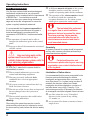
User responsibility
Your fire alarm system should have been designed,
installed and commissioned to your site specific
requirements and in accordance with the requirements
of BS5839 Part 1. You should have received
instructions about your system during the handover
stage and must make arrangements to ensure the
system is regularly tested and maintained.
It is recommended that the person responsible for
the fire alarm system should ensure the system is
tested and maintained in accordance with the
requirements of BS5839:Part 1 and become familiar
with:
¨ the operation of controls and be able to
interpret the indications given at the control
panel
¨ A different manual call point of the system
should be tested to ensure the system is
capable of operating under alarm conditions.
¨ The operation of the alarm sounders should
be checked, which also reminds the
occupants that there is a fire alarm system
which gives a particular sound output.
"
The test should be performed
at a regular time to avoid confusion
between a test and a genuine fire alarm.
The alarm receiving centre must be
contacted before and after the test to
check alarms are received and also to
avoid unwanted alarms.
¨ keep up to date all documentation associated Quarterly
with the system.
&
Any servicing work on the
system must be carried out by a
suitably trained person, please refer to
your servicing organisation.
Daily
BS 5839:Part 1, states that the system should be
inspected daily to ensure:
¨ That a normal indication is given at the
At quarterly intervals the system should be inspected
and any work necessary should be performed by a
trained maintenance engineer.
"
For help with service and
maintenance please refer to your servicing
organisation, see contact details entered
in the log book.
Limitation of false alarm
control and indicating equipment.
¨
¨
¨
It is recommended that the person responsible for the
fire alarm system should arrange for suitable
That any previously indicated fault
investigation and appropriate action on occasion of
conditions have received appropriate
every false alarm. For a system having less than 40
attention.
automatic fire detectors installed, an in-depth
All system events are entered into the Log
investigation should be instigated on occurrence of
Book for future reference.
two false alarms in any rolling 12 months. For a
That the use of the 'area(s) that are inspected' system having more than 40 automatic fire detectors
has not changed since the system was
an investigation should be instigated if there has been:
designed.
¨ one false alarm for every 20 installed
¨ That no unsafe practices that could lead to
fire are being undertaken.
Weekly
When testing the system there may be a need to
isolate ancillary outputs and it is important to contact
the alarm receiving centre before and after the weekly
test.
4
detectors in the system in any rolling
12 months, or
¨ two or more false alarm occurrences from a
single device.
SenTRI ONE fire system
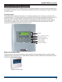
Control and indicating equipment
On occurrence of a fire, fault or disablement event in the protect premises, the event is quickly indicated at the
control panel. The panel controls are password protected and must only be operated by the person responsible
for the fire system.
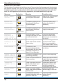
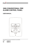
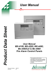
Control panel
The control panel is the heart of the system. It is normally located near to the main entry or exit point of the
protected premises. The control panel continuously monitor devices that are connected to the device loop. The
device loop cable is routed through the protected premises to cover all areas with both ends of the loop
terminating at the control panel. On the loop cable are installed devices such as fire sensors that constantly
monitor the environment for fire. Alarm devices on the loop provide alert and evacuation alarm to warn
occupants in the protected premises in the event of a fire.
Display
Menu navigation controls
Emergency controls
Fault, disablement and
status indicators
Zone indicators
Common indicators
042bc/14
0XXxx
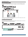
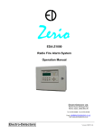
Repeat indicator panel
There may be one or more repeat indicator panels installed in the protected premises to provide secondary
indications of the system events. The repeat indicator panels are usually located near to secondary entry and
exit points of the protected premises.
Repeat indicator panel
5
Operating instructions
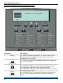
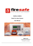
Description of controls and indications
09:37 Thu 01/04/10
SenTRI Fire Alarm System
one
Menu
Cancel
Buzzer
Sound
Alarms
Reset
Silence
Alarms
Disablement
Test
Delay
Verify
System Fault
Power Fault
Sounder Fault
Sounder
Disablement
Zone 1
Zone 2
Zone 3
Zone 4
Zone 5
Zone 6
Zone 7
Zone 8
Zone 9
Zone 10
Zone 11
Zone 12
Zone 13
Zone 14
Zone 15
Zone 16
FAULT
Indicators
Display
POWER
POWER
FIRE
Description
The display provides messages of the system status under
normal and event conditions, by means of 8 lines by 40
characters per line display.
The POWER light when illuminated indicates that a supply to
the panel is present.
[green LED]
FIRE
[red LED]
FAULT
[amber LED]
6
The COMMON FIRE light when illuminated indicates that a
FIRE has been detected in the protected premises.
The COMMON FIRE light when flashing indicates the external
evacuate input is active.
The COMMON FAULT light when illuminated indicates that a
FAULT has been detected in the fire detection and alarm
system.
SenTRI ONE fire system
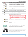
ZONE n
[red LEDs]
Delay
[amber LED]
Verify
[amber LED]
Test
[amber LED]
Sounder Fault
[amber LED]
Power Fault
[amber LED]
System Fault
[amber LED]
The ZONE 'n' light when illuminated indicates that a FIRE has
been detected in the respective zone(s). ('n'=zone number)
The DELAY light when illuminated indicates that Day Mode
delays are setup and active on the panel.
The VERIFY light when illuminated indicates the verification
delay is active.
The TEST light when illuminated indicates that one or more
zones are in Test mode.
The SOUNDER FAULT light is always illuminated with the
FAULT light, which indicates that there is a sounder fault.
The POWER FAULT light when illuminated indicates the
battery or mains supply to the panel has failed.
The SYSTEM FAULT light when illuminated indicates that a
fault has occurred with the system processor.
&
It is very important to investigate this fault
because the fire alarm system may not be able to detect
fires.
Disablement
[amber LED]
Sounder
Disablement
[amber LED]
Controls
The DISABLEMENT light when illuminated indicates that a part
of the system has been disabled.
The SOUNDER DISABLEMENT light is always illuminated with
the DISABLEMENT light, which indicates that there is sounder
disablement.
Description
Menu
The two selection buttons with a line above allow selection of
an option on the display. In this example the option is MENU
and on pressing the corresponding button the menu is
displayed.
These buttons are used to scroll through a range in a form.
They are also used to scroll through the alphabet or number
range when entering a label or a PIN code.
7
Operating instructions
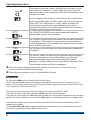
Verify v
This button is normally used to highlight the next menu or sub
menu option for selection. It is also used to scroll to the next
character position when entering a PIN code and similarly when
editing a text label.
In a fire condition this button is a selection for the 'Verify' option,
which is available when the 'Day mode' option is active and the
'Delay LED' is lit. Selecting the 'Verify' option will delay the
alarm further to provide the responsible person(s) time to
investigate the cause of the alarm and the option of cancelling
the alarm within the delay time period.
Cancel
Buzzer
uv
Sound
Alarms
v
Silence
Alarms
v
Reset
v
The CANCEL BUZZER button when pressed will stop the
internal panel buzzer from sounding.
The SOUND ALARM button will activate all the alarm sounders
in the system. This button is only pressed in an emergency or
at other agreed times, for example when conducting a sounder
test or practice evacuation.
The SILENCE ALARM button will silence the alarm sounders in
the system.
The RESET button will clear any fire indication and messages
and return the panel to its normal condition, providing the
devices generating alarm have been cleared for normal
operation. If a fire condition occurs immediately after reset then
the indicated device should be investigated.
u This button may be configured to site specific operation at Access level 1 or Access level 2, latter
requiring a Customer mode PIN (factory setting).
v These buttons are operable on entry of a Customer Mode PIN code.
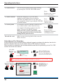
Navigation
On selecting the Menu option the display shows the user menu.
The functions and submenu options accessible are determined by the access level. The access level 1 is
without a PIN code entry, while access level 2 (Customer Mode) or higher access level will require a PIN code
entry. Normally the panel is at access level 1.
The instructions covered here are of all those menu options under Access levels 1 and 2.
At any level in a menu momentarily selecting the Back option will abort the operation.
At any point in a form selecting the Quit option will disregard and not save entries made and return to the menu
display. Once a form is filled-in you must select the Save option to acknowledge and save any changes made.
If the time taken between button presses exceed a few minutes then the panel will automatically revert to
system status indication.
The Customer Mode PIN code is programmed during the commissioning of the system and is passed on to
the person(s) responsible for the fire alarm system on site.
8
SenTRI ONE fire system
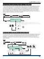
Normal condition
When the system is operating normally with no fault or disablement condition present then the panel indications
are as follows:
¨ the display will show the SenTRI system message
¨ and only the POWER light is lit.
042bc/14
16:15 Thu 01/04/10
POWER
one
[green LED]
Menu
SenTRI ONE Fire Alarm System
When at access level 2 the display reads :PANEL IN CUSTOMER MODE
When at access level 3 the display reads :PANEL IN ENGINEERING MODE
When at access level 4 the display reads :PANEL IN MAINTENANCE MODE
NOTE: The Engineering and Maintenance Modes are not covered in this manual.
How to enter 'Customer mode' PIN for access to Level 2 menus
A Customer mode PIN code is normally set up by the servicing organisation during commissioning of the
system. The Customer mode PIN code (password) is for the end user, the person(s) responsible for the fire
alarm system. The Customer mode allows access to menu options that are required to be protected by coded
entry. It is important the PIN code is changed on a regular basis for security, ask your servicing organisation for
advice on changing the PIN code.
Menu
User
When prompted for
a PIN code only these
procedures apply.
Select
System
>
Select
Select
Code
10:15 Tue 12/01/10
User Access Code Entry
Enter User Code
Accept
: [0***]
Accept
Quit
Factory set access level
code for customer mode is:
0000
Use these buttons to scroll to a
To move to the next
required number of your PIN from
character (or PIN
a range 0 to 9.
Code) position.
Then repeat the sequence for the
next character (or PIN code) position.
Other Access levels exist
for engineering use only
and are not covered in this
document.
9
Operating instructions
Weekly tests
Every week during normal working hours the fire detection and alarm system should be tested. It is important to
inform the alarm receiving centre of the fire test. A fire test reminder will appear on the display every week on
the specified day if the option is turned on. The fire test should be conducted at a specific time of the day.
A weekly test can be carried out at a manual call point without breaking the call point glass by use of a test key.
How to enter the Weekly test mode
To put the system in a weekly test mode and to identify the next device to be tested, carry out the following
procedure at the panel.
¨ First enter the Customer Mode by entering Access Level 2 PIN code, see page 9.
¨ Set the system for 'Weekly Test' by following these procedures.
Menu
User
Select
System >
Select
Start/Stop
Select
Select
Weekly Test >
10:15 Mon 11/01/10
Start Weekly Fire Test
Warning!
Selecting 'FIRE TEST’ causes all
zones to enter test state
ARE YOU SURE YOU WANT TO PROCEED?
Yes
Yes
NO
Test
Weekly Fire Test
10:15 Mon 11/01/10
ALL ZONES IN TEST STATE
Next manual call point to be tested:
Dev 004
Device 4
Zn 001
Zone 1
+/- More
Quit
¨ Go to the manual call point to be tested, its green light will be giving a flashing indication.
Insert the test key into the Call point keyhole. The keyhole is located on the bottom-centre front
face of the call point and is concealed behind a slider cover. Turn the key one quarter of a turn
clockwise.
Device to be tested
Manual Call point
1 ZONE IN FIRE
Green LED
FIRE TEST IN PROGRESS
XX:TEST(S)
Menu
Audible
Buzzer
ZONE 1
Test Key
FIRE
First fire indication
(flashing LED)
[red LED]
Test Fire
Alarm
key
On
Flashing
Test duration is 5 seconds before
automatic SILENCE ALARMS and
further 5 seconds before RESET.
Common fire LED
(Steady indication)
The PLANT equipment will not
operate during ‘Fire Test’ condition.
¨ Check the alarms are sounding in the building and an indication is given of the fire event.
¨ Turn the key anticlockwise one quarter of a turn and remove it from the call point.
Record the event
10
Make an entry in the log book of the event for future reference.
SenTRI ONE fire system
How to exit the Weekly Test mode
When the weekly test is over you will need to exit the weekly test mode.
¨ Ensure you are still in the Customer Mode at Access level 2, see page 9.
¨ To exit the 'Weekly Test' follow these procedures.
Menu
User
Select
Select
System
Start/Stop
>
Weekly Test >
Select
Select
10:15 Tue 12/01/10
Stop Weekly Fire Test
Warning!
Stopping ‘FIRE TEST’ will cause all
zones to leave the test state
Select
ARE YOU SURE YOU WANT TO PROCEED?
Yes
No
Yes
Test
How to view the active Test log
The active test log will show the zones that are in weekly test mode, that is if weekly test is active. Additionally
the test log will also show any zone that have been manually placed in test. The 'Test' light will be lit. Follow
these procedures to view the Test log:
Test
[amber LED]
Menu
Logs
Select
Active
>
Select
Test >
10:38 Mon 11/01/10
Test Log (
Select
View
Select
2)
1:
Zone in Test
Zn 16:Zone 16
10:37:20 Mon 11/01/10
Quit
Quit
To view other active
test events
11
Operating instructions
How to manually raise an alarm of FIRE
If you see a fire in the protected premises and want to raise a fire alarm to warn occupants in the
building, you can do this manually by:
¨ going to the nearest manual call point that is located away from the fire hazard.
¨ press hard with thumb onto the centre of the glass until it breaks.
Manual Call point
Sound
Alarms
At any time you can press
the ‘Sound Alarms button
to activate alarms site wide.
You will need to be in the
Customer Mode, see page 9.
Displayed if Fault, Disablement or Test Event is present.
Typical example of multiple fires
FAULT:0 DISABLE:1 TEST:0
17:53 Mon 11/01/10
17:52
FIRST FIRE: Zone 1
Dv 02 DEVICE 2
LATEST: Zone 4
17:53
Dv 03 DEVICE 3
MA Disabled
Menu
Logout
How to scroll multiple fire events
ZONE 1
[flashing indication of first zone in fire]
ZONE 4 + other zone in fire
Audible
Buzzer
[steady indication of other zones in fire]
FIRE
To view other active events
[red LED]
[Common fire indication]
How to cancel the fire buzzer
Key
MA + Sector X-Y, Z Disabled
On
Cancel
Buzzer
Where ‘Master Alarm (MA)’ and/or alarm
‘Sectors’ are disabled in the system then
they will be displayed in place of ‘Total fires’.
Audible
Buzzer
Flashing
NOTE: Where applicable the PLANT equipment will
operate in a Fire Condition.
To operate the alarm controls you will need to be in the Customer Mode at Access level 2, see page 9.
To silence
alarms
When the emergency is over the alarm
sounders can be silenced.
Silence Alarms
Press:
Display reads:
'Alarms silenced'
To reset system
To return the system to normal condition clear
any residual smoke or heat from devices, reset
any fire inputs and reset Manual call points.
Ensure the fire system is checked by your
servicing organisation if there has been fire
damage in the protected area.
Reset
Press:
Display reads: 'Resetting
fire - please wait.
Resets all plant
equipment controlled via
'Plant Sectors'.
Record the event
12
Make an entry in the log book of the event for
future reference.
SenTRI ONE fire system
Automatic detection of FIRE
A fire in your protected premises is automatically sensed at any one of the fire detection devices
installed. A fire detection can be from a fire sensor, manual call point or fire input from an
interface. The control panel actions the alarm sounders in the system and at the same time give
details of the fire event. The event indication is repeated at all repeat indicator panels in the
system.
Typical example of a fire event
FIRST FIRE: Zone 1
Dv 02 DEVICE 2
17:53 Mon 11/01/10
17:52
MA + Sector X-Y, Z Disabled
Total Fires: 1
Menu
Audible
Buzzer
Where ‘Master Alarm (MA)’
and/or alarm ‘Sectors’ are
disabled in the system then
they will be displayed in place
of ‘Total fires’.
Logout
ZONE 1
[flashing indication of first zone in fire]
ZONE x (other zones in fire)
[A steady indication is given of subsequent zones in fire]
FIRE
Key
[red LED]
NOTE: PLANT equipment
will operate in a Fire Condition.
Multiple fires
On
[Common fire indication]
Flashing
The 1st Fire will always appear at the top part
of the display. Latest fires appear beneath the
1st Fire message and multiple fires can be
scrolled.
The zone light(s) show zones in fire condition.
The first zone to go into a fire condtion will be
indicated by a flashing zone light, all other
zones in fire will give a steady indication.
To view other active events
Use these buttons to
scroll through the fire
events.
Each fire is logged in the Historic Events log,
which can be recalled using the menus. See
How to view the Historic Events.
To operate the following controls you will need to be in the Customer Mode at
Access level 2, see page 9.
To activate
Verification delay
The 'Verify' option will appear on the display
if the 'Delay' light is lit. On selecting the
'Verify' option there is a further delay before
alarm activation giving time to investigate the
cause of the alarm.
Verify
Press:
Verify
[amber LED]
13
Operating instructions
To cancel buzzer
Cancel Buzzer
You can stop the panel buzzer from sounding
by pressing the CANCEL BUZZER button.
Press:
Display reads ' Local
buzzer cancelled'.
To silence alarms
To reset system
Record the event
When the emergency is over the alarm
sounders can be silenced by pressing the
SILENCE ALARM button. At any time you
can resound the alarms by pressing the SOUND
ALARMS button.
To return the system to normal condition clear
any residual smoke or heat from device(s),
reset manual call point(s) and reset any fire
inputs. Then press the RESET button
Ensure the fire system is checked by your
servicing organisation if there has been fire
damage in the protected area.
Silence Alarms
Press:
Display reads:
'Alarms silenced'
Reset
Press:
Resets all plant
equipment controlled
via 'Plant Sectors'.
Make an entry in the log book of the event for
future reference.
Coincidence Fire Detection
If there are area(s) in your protected building configured to operate coincidence fire detection, then the first
automatic detection of fire event in that area will cause a FIRE indication at the panel.
When a second fire is detected in the coincidence detection area then the system will go into a FULL FIRE
condition and sound the fire alarms.
First FIRE
After investigation in to
the cause of First FIRE
and if it is appropriate to
do so you can RESET the
system as described above
FIRE MESSAGE
ZONE n
[steady indication of a fire]
Audible
Buzzer
The above indications are given when the system is set up for ‘Zone Coincidence’
only. A system set up for ‘Detector coincidence’ will only give a fire message, there
is no light indication nor an audible indication on First Fire.
Second FIRE
Procedures to
SILENCE ALARMS
and RESET the
system are as for
FIRE Condition
FIRE MESSAGE
ZONE n
[steady indication of fires]
FIRE
[Common fire indication]
all red LEDs
14
Audible
Buzzer
SenTRI ONE fire system
Fault condition
A fault in the system, such as the failure of mains power to the panel or removal of any monitoring device will
cause a Fault condition to appear at the control panel. The control panel will provide details of the event, this
event indication is repeated at all repeat indicator panels.
Typical indications of Fault events
FAULT:6 DISABLE:0 TEST:0
LATEST FAULT AT 11/01/10 16:15
Device Lost
Dv 145: Room 1 first floor 1
Zn 001: Zone 1
Menu
16:15
[amber LED]
Quit
How to scroll multiple fault events
FAULT
Common FAULT indication
may be accompanied with:
Audible
Buzzer
Power Fault
[amber LED]
Sounder Fault
[amber LED]
To view other active fault events
System Fault
[amber LED]
To cancel fault
buzzer
You may need to enter the Customer mode PIN, see page 9
To stop the panel buzzer from sounding press:
Cancel Buzzer
Display reads:
'Local Buzzer Silenced'
What must be
done?
You need to ensure the panel is returned to normal
condition.
&
Only the trained engineer who is responsible for the fire alarm system
must attempt any fault rectification work. For advice please call your servicing
organisation, see contact details in the Log book.
Record the
event
Make an entry in the log book of the event for
future reference.
Multiple faults
On the top line of the display the word 'FAULT'
appears followed by a number 'n'. The 'n' indicates
the number of faults present in the system.
Each fault is logged in the Historic Events log,
which can be recalled using the menus. See How
to view the Historic Events.
15
Operating instructions
Typical fault messages
The table below is for guidance only and shows some of the more typical fault messages and indications that
may appear at the panel. It also gives the meaning and possible rectification action for each fault event.Only
the trained engineer who is responsible for the fire alarm system must attempt any fault rectification
work. For advice please call your servicing organisation, see contact details in the Log book.
Message
Mains supply
failed
Indication
FAULT
Meaning
The mains supply to the
control panel has failed.
Possible action
Restore the mains supply
to the control panel.
The battery supply to the
control panel has been
fully discharged.
Check the battery and
replace the battery if
necessary.
The battery supply to the
control panel has been
disconnected.
Reconnect the battery
supply to the panel.
Power Fault
Batteries
discharged
FAULT
Power Fault
Batteries
disconnected
FAULT
Power Fault
External
Evacuate or
Class Change
input OC or SC
Master
Alarm(s) OC or
SC n
FAULT
FAULT
Sounder Fault
Lost Device
FAULT
Sounder Fault
Sensor out of
specification
Loop Wiring
changed SC
Interface
channel OC or
SC
Device Mains
failed
Device Battery
fault
16
FAULT
FAULT
FAULT
FAULT
FAULT
The Evacuate or Class
Check the wiring and
Change input has an open ensure the end-of-line
or short circuit fault.
devices are connected in
the circuit.
There is an open or short Check the wiring and
circuit fault on the master ensure the end-of-line
alarm wiring.
device is connected to
each master alarm circuit.
The device is not
Check the connections to
communicating with the
the device.
control panel via the Loop.
Additional indication is
given if it is a Sounder.
The device indicated is not Device needs replacing.
functioning correctly.
There is a short circuit on
the loop wiring.
Identify the device where
a cable fault has occurred
and remove the fault.
There is an open or short Locate and remove the
circuit fault on the input
wiring fault. Ensure the
line of an interface.
end-of-line device is
connected to the circuit.
There is a mains supply
Check the fuse and
failure at a mains powered mains supply to the unit.
interface unit.
The batteries at mains
Check the batteries and
powered interface unit has replace them if
failed the load test.
necessary.
SenTRI ONE fire system
Disablement condition
A disablement condition is the manual or automatic disablement of a part of the fire detection system. An
automatic disablement may be pre-configured for your premises to disable smoke sensors, in areas where
smoke may be present for example during the normal working hours. Also a disablement may be necessary
where building work is being undertaken that could result in a false alarm.
16:15 Thu 01/04/10
Disablement
SenTRI ONE Fire Alarm System
one
[amber LED]
FAULT:0 DISABLE:1 TEST:0
Sounder
Disablement
[amber LED]
A message is given and the ‘Sounder Disablement’ light is lit when
an alarm sector, sounder device or master alarms are disabled.
16:15 Mon 11/01/10
Disablement Log (
1:
Loop Disabled
1)
16:15:47 Mon 11/01/10
For details of disablement,
see How to view or print
active Disablement events.
CAUTION: Any changes to
the setting of an automatic
disablement must only be
attempted by a trained
engineer who is
responsible for the fire
alarm system, see contact
details in the Log book.
Quit
What must be done?
Investigate the reason for the disablement and re-enable if appropriate.
Record the event
Where necessary make an entry in the log book of the event for future
reference.
Multiple
Disablements
The default page will have the word 'DISABLE' followed by a number
'n'. The 'n' indicates the number of disablements present in the system.
Each disablement is logged in the Historic Events log which can be
recalled, using the menus, see How to view the Historic Events log.
Typical Disablement Messages
The following table show some typical disablement messages and indications that may appear at the panel.
Message
Indication
Meaning
Action
Zone
Disabled
Disablement
The displayed zone has
been disabled.
If manually disabled then
investigate and if necessary
re-enable the zone.
Device
disabled
Disablement
The device connected to
the loop circuit has been
disabled. Additional
indication is given if it is a
sounder device.
If manually disabled then
investigate and if appropriate
re-enable the device.
Sector
disabled
Disablement
The fire alarm sector has
been disabled.
If manually disabled then
investigate and if appropriate,
re-enable the sector.
Master
alarm(s)
disabled
Disablement
The master alarms have
been disabled.
If disabled then investigate
and if appropriate, re-enable
the master alarms.
Sounder
Disablement
Sounder
Disablement
Sounder
Disablement
17
Operating instructions
To carry out a display test
You can test the message display and the lights on the control panel. To operate the'display test' option you
will need to be in the Customer Mode at Access level 2, see page 9. Then carry out the following operation.
Menu
User
Select
Select
Display Test
Test duration is
approximately
8 seconds.
Select
System >
[red LEDs]
[amber LEDs]
FIRE
[red LED]
FAULT
POWER
[amber LED]
Audible
Buzzer
[green LED]
The display will clear, the indicators will illuminate, the buzzer sounds and then the display shows the system
status message. The test will run for several seconds.
How to change time and date
The time and date shown on the panel can be changed or adjusted. To make the changes you will need to be
at Access level 2, see page 9, then follow these procedures:
Menu
Settings
Select
System
>
Select Clock
Select
To scroll range
12:30 Tue 12/01/10
Save
To move to
the next setting
System Clock
Current Time :
Current Date :
Current Day
:
Save
18
Enter the current time in hours and minutes
Enter today’s date
The day of the week is displayed here
[12]:[30]
[12]/ [ 1]/[2010]
Tuesday
Quit
SenTRI ONE fire system
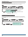
How to view or print the Historic Events log
The past events of the systems are stored in the Historic events log of the panel. To view the Historic events
log follow these procedures:
Menu
Logs
Select
Historic
Select
>
6:15 Mon 11/01/10
View
Select
Print
Select
Event Log (200)
1:
Device Disabled
Device 002 Loop
10:37:20 Sun
10/01/10
01
Quit
Quit
To view other
historic events
The ‘Print’ option is only available
in Customer Mode and only when
a printer is connected to the panel.
6:15 Mon 11/01/10
Print Event Log (200)
First Event to Print [175]
Last Event to Print [200]
Print
Print
Quit
The event number '1' is always the most recent event.
How to view or print active Fire events
All active fire events that are still present and have not cleared can be viewed or printed at any time. The fire
lights will be lit at the panel. Follow these procedure to view the fire events log:
FIRE
ZONE 1
First fire indication
(flashing LED)
(Steady indication)
ZONE 4 + other zones in fire
(steady LED)
Audible
Buzzer
Key
(all red LEDs)
On
Flashing
Menu
Logs
Select
Active
Select
>
Fire
>
Select
17:54 Mon 11/01/2010
Fire log (2)
1:
Dv 02 DEVICE 2
View
Print
17:53:58 11/01/2010
Quit
Select
Select
MA + Sector X-Y, Z Disabled
To view other active events
17:56 Mon 11/01/10
Print Active Fire Log
WARNING ! - This option will print all
entries in the active fire log!
The ‘Print’ option is only applicable
if a printer is connected to the panel.
Print
Where ‘Master Alarm (MA)’
and/or alarm ‘Sectors’ are
disabled in the system then
they will be displayed in place
of ‘Total fires’.
Print
Quit
19
Operating instructions
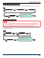
How to view or print active Fault events
All active fault events that are still present and have not cleared can be viewed or printed at any time. The fault
light will be lit. Follow these procedures to view the active fault events log:
FAULT
+ May be accompanied with other Fault indicators
[amber LED]
Menu
Logs
Select
Active
>
Select
Fault >
16:15 Mon 11/01/10
Fault Log ( 2)
1:
16:10:45 Mon 11/01/2010
Loop wiring open circuit
Dv 002:Device 2
Select
Quit
Select
View
Quit
Print
Select
To view other active fault events
16:15 Mon 11/01/10
Print Active fault Log
The ‘Print’ option is only available
in Customer Mode and only when
a printer is connected to the panel.
WARNING ! - This option will print all
entries in the active Fault log !
Print
Print
Quit
How to view or print active Disablement events
All the active disablement events that are still present and have not cleared can be viewed or printed at any
time. The disablement light(s) will be lit. Follow these procedures to view the disablement events log:
Disablement
[amber LED]
+ Sounder Disablement
LED may also be lit
Menu
Logs
Select
Active
>
Select
Disablement >
16:15 Mon 11/01/10
Disablement Log ( 1)
1:
10:15:47 Mon 11/01/2010
Device Disabled
Device 002 Loop 01
Select
View
Select
Quit
Quit
Print
Select
To view other active disablement events
The ‘Print’ option is only available
in Customer Mode and only when
a printer is connected to the panel.
16:15 Mon 11/01/10
Print Active Disablement Log
WARNING ! - This option will print all
entries in the active Disablement log !
Print
20
Quit
Print
SenTRI ONE fire system
How to put the system in 'Day mode' or 'Night Mode'
The fire system normally operates in the 'Night Mode', which means all the fire alarms operate without a delay
in the event of a fire detection. The 'Day Mode' allows a delayed operation of fire alarms. The 'Day mode' is
active when the 'Delay' light is lit. The delay durations are programmed to site specific requirements by the
servicing organisation. The 'Day Mode' will remain active for a predefined period of time. You can manually
place the system in 'Day mode', 'Night Mode' or 'NONE'. Selecting the 'NONE' option will revert the panel
delays to operate according to the 'Day mode delay settings' made during commissioning. You will need to be
at Access level 2 to change 'Day mode' settings, see page 9.
Menu
User
Select
System
Select
>
Day Night Mode
10:15 Wed 10/02/10
Select
Day Mode Control
Mode: CALENDAR
Level 2 Override:
State: NIGHT
[NONE ]
Save
Save
Quit
NONE The ‘NONE’ selection means the Day/Night override is Off.
Therefore the panel delays will operate according to the
Day mode settings made during commissioning, ie with Calendar,
ON or OFF settings, therefore the Delay LED may be ON or OFF
depending on these settings.
Delay
To scroll range
Night [amber LED]
Delay
Day
[amber LED]
How to view, enable/disable or test mode a Zone
The 'Zone' form allow a zone to be placed in test mode and also allow a zone to be disabled or enabled. Notice
the 'Test' light is lit if a zone is in Test mode and the selected zone will function as described for 'weekly test',
see page 10. A disabled zone will not detect fires from sensors or manual call points in the zone, the
'Disablement' light will be lit. To access the 'Zone' form you will need to be in the Customer Mode at Access
level 2, see page 9.
Menu
User
Select
Select
Zones
Select from a range of zones - 1 to 16
10:15 Tue 12/01/10
Zone : [ 1]
Label: Zone Label
Save
Status : [ ENABLED ]
Test : [ NO ]
Save
To scroll range
To move to
next setting
Quit
Place the zone in Test mode? NO (factory default setting) or YES,
for the latter a test indication is
given:
Test
[amber LED]
Select the zone status:
Zone ‘ENABLED’ (factory default setting)
or Zone ‘DISABLED’, for the latter
a disablement indication is given:
Disablement
[amber LED]
21
Operating instructions
How to view or enable/disable an alarm Sector
The 'Sector' form displays the label given to a sector, its activation control and current status. You can also use
this form to manually disable or enable a sector. A disabled sector will not activate its alarm devices in the
event of a fire and the disablement light(s) will be lit. To view the 'Sector' form you will need to be in the
Customer Mode at Access level 2, see page 9.
Menu
Select
User
Alarms
Select
>
Sectors
Select from a range of sectors - 1 to 16
10:15 Tue 12/01/10
To scroll range
Sector: [ 1]
Label : Sector Label
Select
Activation Control :
Status Control:
Current State: IDLE
Save
EVACUATE
[ENABLED
]
To move to
next setting
Save
Quit
Select sector status:
Sector ‘ENABLED’ (factory default setting) or Sector ‘DISABLED’,
the latter will give the following indications:
Disablement
[amber LED]
Sounder
Disablement
[amber LED]
How to view the Loop map and Device details
The 'Loop map' form lists all the devices connected to the loop circuit. You can select a device from the map
and view the 'Device details', which gives information on device label, type, status and assignment. To view
'Loop map' and 'Device details' you will need to be in the Customer Mode at Access level 2, see page 9.
Menu
User
Select
Loop
>
Select
Select
Devices
The + indicates the device is SAFE addressed
10:15 Mon 11/01/10
Loop
1+
2
3
4
Map
9 Device
9 Device
9 Device
9 Device
Select
‘Loop map’ form showing devices
connected to the loop circuit.
1
2
3
4
DEVICE
Select
Loop Map
1+ 9 Device 1
|
20 9 Device 20
9 Device 21
9 Device 22
23 9 Device 24
The Devices 21 and 22 are indented,
which implies they are on the spur
circuit off Device 20.
Quit
Select from a range of devices - 1 to 127
Device :
Label :
Type
:
Status :
Assigned
Save
22
10:15 Mon 11/01/10
[ 1]
Device Label
2
O H Sensor Sounder Strobe
ENABLED
to Zone 1
Quit
Device details form
Save
To scroll range
Certain devices will not be assigned to a zone, this
line may or may not be displayed.
SenTRI ONE fire system
How to view channel details of interface devices
The 'Channels' form show details of a 4-channel interface device on the loop circuit. To view the details of a
4-channel device you will need to be in Customer mode at access level 2.
Menu
User
Select
Select
Loop
>
Select
10:15 Tue 12/01/10
Channel:[Device 18 Channel 1]
Label : Channel Label
Status : ENABLED
Channels
Save
To scroll range
of channels of
4-channel interface
devices
on the loop
WARNING: Find will action relay outputs!
Back
How to enable/disable master alarms, fire relay and evacuate input
The 'Other alarms' form allows the disablement or enablement for Master alarms, Fire relay and Evacuate
input. If any of these features are disabled then the 'Disablement light(s) are lit, you will need to be in the
Customer Mode at Access level 2, see page 9.
Menu
User
Select
Alarms
>
Select
Other
10:15 Mon 11/01/10
Save
Alarms Status
Select
State
Master Alarms : INACTIVE
Fire Relay
: INACTIVE
Evacuate Input: INACTIVE
Enable Status
[ ENABLED ]
[ ENABLED ]
[ ENABLED ]
Save
Quit
To scroll range
To move to
next setting
Alarm status of:
Master Alarm can be (INACTIVE) ENABLED [Factory default setting) or DISABLED
Fire Relay can be (INACTIVE) ENABLED [Factory default setting) or DISABLED
Evacuate Input can be (INACTIVE) ENABLED [Factory default setting) or DISABLED
Disablement
[amber LED]
Additional indication
for Master alarm
disablement:
Sounder
Disablement
[amber LED]
23
Operating instructions
How to view the Loop status
The 'Loop status' form provides information about the number of devices on the loop circuit and the status of
the loop circuit. This form is accessible in the Customer Mode at Access level 2, see page 9.
Menu
User
Select
Loop
Select
>
Status
Back
10:15 Mon 11/01/10
Select
Loop status
Current status :
Started
Total devices :
127
Wiring Status :
Complete
Last device found at address : 127
Here the current loop
status is ‘Started’
This value is the total number
of devices found on the loop
Back
The device number of the last device found
on the loop circuit
How to view panel 'Firmware' version
To check you have the required panel firmware to support the installed system, you can view the firmware
version of the Main Controller, Loop driver and PSU. This form is accessible in the Customer Mode at Access
level 2, see page 9.
Menu
Engineering
Select
System
>
Select
Versions >
10:15 Tue 12/01/10
Firmware Version Numbers
Select
Firmware
Select
Main Controller
Loop Driver
Vig Compact PSU
V2.37
V1.03
V2.05
Back
23-01-10
15-01-09
01-07-08
Back
24
SenTRI ONE fire system
How to view 'Site data' version
You can view site data version. This form is accessible in the Customer Mode at Access level 2, see page 9.
Menu
Engineering
Select
System
>
Select
Versions
10:15 Mon 11/01/10
Site Data Version Details
Select
Site Data
Version Number:
Select
Last Updated:
Back
003
11-01-2010
Back
The 'Loop Repair' option
"
Any wiring fault on the system must be rectified by an engineer from the
servicing organisation, for contact details see the log book. A wiring fault will require
correction to the wiring before running the 'Repair' option at the main panel.
The 'Loop Repair' option is normally used by a trained person when rectifying wiring faults. Under normal
circumstances it is unnecessary to use this option. The 'Repair' option is accessible in the Customer Mode at
Access level 2, see page 9.
Menu
User
Select
Loop
>
Select
10:15 Tue 12/01/10
Warning!- Ensure that the loop wiring faults
have been cleared before continuing
with this function!
Repair
Select
Yes
ARE YOU SURE YOU WANT TO PROCEED?
Yes
No
25
Operating instructions
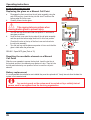
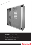
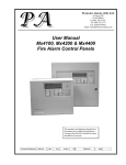
General Maintenance
Replacing the glass on a Manual Call Point
a.
Disengage the front cover from the call point assembly using the
end of the test key. Insert the key into the slots 'E' and from the
bottom edge lift out the cover.
Carefully remove broken glass.
b.
&
E
YELLOW
ARM
Take appropriate precautions when
clearing broken glass to prevent injury.
c.
Turn the test key such that the tab is at position 'F' and insert a
new glass as shown.
Hook the front cover onto the top edge of the call point assembly
and then push the bottom edge down until it clicks into position.
Check both hooks on the top of the front cover are locked onto
the call point assembly.
Turn the test key anticlockwise one quarter of a turn such that the
glass is held under the yellow arm.
d.
e.
GLASS
F
SEN-891 Spare MCP glass (Pack of 10)
Resetting the resettable element on a Manual
Call Point
Slide the cover upwards to expose the key hole. Insert the test key in
the keyhole and turn it clockwise by one quarter of a turn. Then turn the
test key anticlockwise by one quarter of a turn to reset the call point
element.
Cover
Test Key
Battery replacement
It is recommended where batteries are installed they must be replaced at 4 Yearly intervals from the date the
system is first commissioned.
"
Any servicing work on the system must be carried out by a suitably trained
person, such as an engineer from the servicing organisation.
26
27
SELECT
Access Level 2
(Customer)
Factory default
PIN: 0000
SELECT (P20)
SELECT (P11)
Disablement >
Test
>
SELECT (P19)
SELECT (P20)
Print
View
SELECT (P25)
Repair
Status
SELECT (P22)
SELECT (P23)
SELECT (P24)
Channel
SELECT (P23)
Other
Device
SELECT (P22)
SELECT
SELECT (P24)
SELECT (P25)
Site Data
SELECT
>
Firmware
>
SELECT
(P10 & P11)
SELECT
(P18)
Versions
Start/Stop
Clock
System
SELECT The ‘Print’ option is only applicable
SELECT if a printer is connected to the panel.
SELECT (P18)
SELECT (P21)
SELECT
SELECT (P9)
SELECT
SELECT
>
SELECT
System
Engineering
Settings
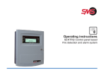
Where you see ‘(Pxx)’ the P signify ‘see page’
and the associated number xx is the page number.
Sectors
Display Test
Day Night Mode
>
>
>
Fire
Fault
SELECT
(P19)
SELECT
>
Loop
Weekly Test
SELECT(P21)
SELECT
Zones
Code
SELECT
Alarms >
System
SELECT
User
Active
>
Historic >
SELECT
Logs
MENU
Customer Mode - Access Level 2 Menu maps
Quick Reference
SenTRI ONE fire system
At the end of their useful life, the packaging,
product and batteries should be disposed of
via a suitable recycling centre and in
accordance with national or local legislation.
delay
[amber LED]
Verify
Audible
Buzzer
Verify
Cancel
Buzzer
IF APPLICABLE
To activate Verification delay
To cancel the panel Buzzer
To reset and return the system to normal condition first clear:
any residual smoke or heat from devices
reset any fire inputs and
reset Manual call point(s)
Ensure the fire system is checked by your servicing organisation
if there has been fire damage in the protected area.
Reset
Silence Alarms
To Reset System
At any time you can press
the ‘Sound Alarms’ button
to activate alarms site wide.
You will need to be in the
Customer Mode
Sound
Alarms
To Silence Alarms
To move to the next character
position (PIN code number) position.
(The factory set PIN for Customer mode is: 0000)
Accept
Enter User Code : [0***]
Use the - and + keys to scroll the number
range to show the first PIN number and
then repeat the sequence for the next
character (PIN code number) position.
On entry of all 4 digits select ‘Accept’.
On pressing the
button you will be prompted to enter
your password (a PIN Code) to access emergency controls.
Silence Alarms
How to Silence Alarms and Reset system
Quick Reference
Operating instructions
0832
Gent by Honeywell
Hamilton Industrial Park, 140 Waterside Road, Leicester LE5 1TN, UK
0832-CPD-1397
SenTRI1
WEEE Directive:
At the end of their useful life, the packaging,
product and batteries should be
disposed of via a suitable recycling centre.
Do not dispose of with your normal household waste.
Do not burn.
EN54-2: 1997, A1:2006
Control and Indicating equipment for fire detection and fire alarm systems in buildings.
7.8
Output to fire alarm devices
7.11 Delays to action outputs
8.3
Fault signals from point
10
Test condition
EN54-4: 1997, A1:2002, A2:2006
Power supply equipment for fire detection and fire alarm systems in buildings.
Gent by Honeywell reserves the right to revise this publication from time to time and make changes to the content hereof without
obligation to notify any person of such revisions of changes.
Hamilton Industrial Park, Waterside Road, Leicester LE5 1TN
28
Fax (UK): +44 (0)116 246 2016
4188-978 issue 2_04-10_SenTRI ONE system oper
Part of Document pack 2534-235 issue 2
%
Telephone: +44 (0)116 246 2100