1
Patent #6,533,067 ; 7,004,284 and other patents pending
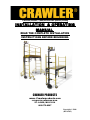
INSTALLATION & OPERATING
MANUAL
READ THE COMPLETE INSTALLATION
INSTRUCTIONS BEFORE BEGINNING
CRAWLER PRODUCTS
www. Crawlerproducts.com
2354 NORTH LINDBERGH BLVD.
ST. LOUIS, MO 63114
866.572.8297
Copyright © 2006
(Revised 5)
Crawler®
Table of contents:
TOOLS & DRILLS NEEDED................1
IDENTIFYING PARTS.........................2
SAFETY..............................................3-6
INSTALLATION..................................7-17
OPERATING MANUAL.......................18-28
WARRANTY........................................29
SAVE THESE INSTRUCTIONS.
Refer to them often
and use them to instruct others.
Crawler®
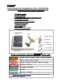
Tools needed for installation of the CRAWLER
(Crawler drive unit & caster locking bar)
1. Framing square
2. Tape measure
3. Standard /metric deep well socket set
4. Adjustable wrench
5. 3/8" Allen wrench (included)
6. 3/16 Allen wrench
7. Electrical tape
8. 1/2" DRILL
9. 3/8" &1/2" DRILL BITS
Drills compatible with the Crawler®drive unit
DC980 – DC983 – DC984 – DC987 – DC988 - DC900KL
13614 – 33614 – 13618 - 13624
0614-20 – 0617-20 – 0624-20 – 0627-20 – 0724-20
SF180-A - SF151-A
DS14DMR - DS18DMR
EY6450
BDDF451 - BHP451
Visit www.crawlerproducts.com for a list of the most current
compatible drill models.
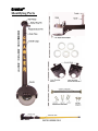
Crawler®
Identifying Parts
Crawler®
GENERAL SAFETY RULES
Don't operate the Crawler above a safe platform height. Use the 2:1
height-to-base width ratio outlined in the “MAX OPERATING HEIGHT”
section of the operating manual.
Don't operate the Crawler with a drill speed other than #1 (low)
selected. The Crawler has been designed to operate at a safe and moderate
speed. Operating the drill at any speed other than #1 (low) will allow the
scaffold to travel at unsafe speeds, possibly causing it to overturn and result
in serious injury to the operator. Operating the drill at any speed other than
#1 (low) will void all warranties and is not compliant with O.S.H.A
regulations.
Don't operate the Crawler without
properly in place.
the caster locking bar secured
Don't operate the Crawler without first making certain you are able to
lock and unlock the casters, using the telescopic “Caster Locking Pole”
supplied. O.S.H.A. Regulations require all casters be locked. To lock
the casters use the CRAWLER “Caster Locking Pole” provided. Lock
all casters before climbing on and off the scaffold, as soon as the
scaffold comes to a complete stop, and before any work begins.
Don't operate the crawler on a grade steeper than 3 degrees.
Don't drive the scaffold through door openings or low clearance areas
with the Crawler attached. Always dismount the scaffold, remove the
drill from the carriage and push the scaffold and Crawler under low
clearance areas.
Don't operate the Crawler without having the telescopic height selector
pin and the safety ring pin securely in place as outlined in the
“TELESCOPIC HEIGHT ADJUSTMENT” section of the operating manual.
Crawler®
GENERAL SAFETY RULES CONT.
Don't drive the Crawler at full speed in the reverse mode. This may
cause the scaffold to flip over if stopped abruptly. Read and fully
understand all safety material in the operating manual and warning labels
posted on the Crawler unit before operating the Crawler.
Don't allow anyone to operate the crawler without first reading and
fully understanding the complete installation and operating manual.
Perform routine inspections on the Crawler's components as outlined in
the “SAFTEY CHECK BEFORE OPERATING” section of the operating
manual.
When raising the telescopic section (the drill carriage and upper tube)
of the Crawler make certain to have a firm hold on the upper tube and
drill carriage before pulling out the selector pin. After the pin is pulled
outward the tubes become disengaged and the upper section will fall,
possibly causing serious injury to the operator.
Don't wear loose clothing or jewelry while operating the Crawler.
Loose clothing and jewelry can become entangled with the scaffold or
Crawler possibly resulting in serious injury. Follow all O.S.H.A.
guidelines concerning movable scaffolds found in O.S.H.A. Publication
3150 (1926.452.(w).
Don't operate the Crawler without first surveying the site for debris
and obstacles which may scotch the casters on the scaffold, possibly
causing it to overturn.
Don't operate the Crawler while under the
alcohol.
influence of drugs or
Don't operate the Crawler if you are tired or have been deprived of
sleep.
Crawler®
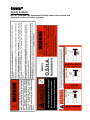
Safety Labels:
NOTE: Read and fully understand all Safety Labels shown below and
displayed on the unit, before operating.
Crawler®
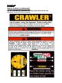
Safety Labels (continued):
NOTE: Read and fully understand all Safety Labels shown below and
displayed on the unit, before operating.
Crawler®
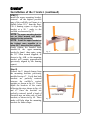
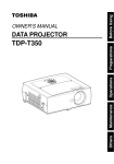
Installation of the Caster Locking Bar
NOTE: Install the caster locking bar prior to installing the Crawler drive unit.
STEP 1)
Rotate the two casters on one end of
the scaffold so both wheels are
positioned
with
the
locking
mechanisms to the outside of the
scaffold, as shown in fig. #1A.
NOTE: It may be helpful to elevate
the scaffold's end frame and
suspend the casters by placing an
object such as a 5 gal. bucket
between the floor and the first rung
of the scaffold, as shown in fig. #1B,
STEP 2)
Remove the nuts and axle bolts from
both casters. Locate the correct
diameter replacement axle bolts.
There are three sizes (5/16", 3/8",
and 1/2") supplied with the Crawler.
Install the new axle bolts so the
threads are facing each other and
pointing to the inside of the scaffold,
as shown in fig. #2A.
Fig. #1A
NOTE: Some caster's axles are
riveted and must be drilled out and
replaced with the axle bolts that are
supplied.
NOTE: Make certain to re-install the
original washers, spacers, and
bushings (as found in the caster
assembly, prior to removing the
original axle bolts).
NOTE: If the axle bolts supplied are
not the proper diameter or length
replace the original axle bolts with
grade 5 hex bolts and lock nuts.
The replacement bolts should match
the diameter of the original bolts
removed and project 7/8" to 1 1/4"
beyond the caster, as shown in 2B.
Fig. #2A
Fig. #2B
Fig. #1B
Crawler®
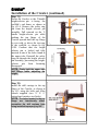
Installation of the Caster Locking Bar (continued)
STEP 3)
With the axle nuts removed check to
see if the top-hat shaped caster
adapters will fit over the new axle
bolts. The adapters are pre-drilled for
use with 5/16" axle bolts. If the axle
bolts on your casters are larger it will
be necessary to enlarge the hole
using a ⅜" or ½" drill bit, depending
on the diameter of the axle bolt.
Some casters may have a raised flap
or contour, making it difficult for
the top-hat shaped adapter to seat
properly. Make certain to rotate the
adapter, aligning the notch in the
adapter with the raised flap or
contoured shape located on the
caster, as shown in fig.#3.
NOTE: Make certain the axle bolt
Fig. #3
does not project beyond the rim of
the top hat adapter.
STEP 4)
Thread the new lock nuts (supplied
with the Crawler) over the end of the
new axle bolts. Tighten the lock nuts
using a deep well socket and socket
wrench, as shown in fig. #4..
NOTE: When installing the axle
nuts use the appropriate size nut for
the axle bolt used. Do not overtighten the axle nuts which will
prevent the caster wheels from
turning freely.
NOTE: The “top-hat” adapters can
Fig. #4
permanently remain on the casters WARNING: DO NOT “OVER TIGHTEN”
and will not affect the performance Make sure the casters turn freely.
of the scaffold, even when the caster
locking bar is not installed.
Crawler®
Installation of the Caster Locking Bar (continued)
STEP 5)
Install the caster locking bar by
pulling outward on the spring pins
and slipping the female adapters
(found on both ends of the caster
locking bar) over the rim of the tophat shaped adapters, as shown in fig.
#5A. Confirm that spring pins are
fully inserted, securing the caster
locking bar to both casters, as
shown in fig. #5B. With the spring
pins fully inserted in both top-hat
adapters the bar is locked, secured,
and will not disengage.
NOTE: After completing Step 5, the
Fig. #5A
front casters are now locked parallel
with the scaffold and will allow the
Crawler drive unit, when installed, to
steer the scaffold in a manner
similar to the operation of an
outboard motor on a fishing boat.
Fig. #5B
Crawler®
Installation of the Crawler
STEP 6)
Install the lower mounting bracket,
centered on the bottom rung of the
scaffold's end frame. (located at the
opposite end of the caster locking
bar, as previously installed in steps
1-5). Use a framing square to align
the bracket at a 90° angle to the
scaffold, as shown in fig. #6A.
Firmly tighten the knurled knob
attached to the lower mounting
bracket by hand, then again
using
the 3/8" Allen wrench supplied, as
shown in fig. #6B, so the mounting
bracket will remain perpendicular
(previously aligned by the framing
square).
Fig. #6A
NOTE:
The lower mounting
bracket has no Allen wrench or
Allen wrench holder attached.
NOTE: If the top of the bottom rung
on your scaffold is less than 11½"
above the floor surface, move the
bottom mounting bracket to the
second rung.
Fig. 6B
The table below shows the min./max. dimensions needed from the finished floor to
the top of the mounting bracket:
Mounting Bracket
Top
Bottom
Minimum
52"
11¾"
Maximum
59¾"
24"
Crawler®
Installation of the Crawler (continued)
STEP 7)
Install the upper mounting bracket,
centered on the highest possible
rung of the scaffold's end frame at or
slightly below 59½" from the floor.
Use a framing square to align the
bracket at a 90 ° angle to the
scaffold, as shown in fig. #7.
NOTE: The upper mounting bracket
has an Allen wrench and holder
attached to the underside.
NOTE: Install the upper bracket on
the highest rung possible at or
below 59½" above the floor surface.
Firmly tighten the knurled knob
attached to the upper mounting
bracket by hand, then again using
the 3/8" Allen wrench supplied, as
shown in fig. #6B, so the mounting
bracket will remain perpendicular
(previously aligned by the framing
square).
Step 8)
Remove the U shaped clamps from
the mounting brackets previously
installed in step #7. Verify that both
brackets are perfectly centered
between the scaffold’s vertical
uprights, as shown in fig. #8. If not,
adjust the brackets to the center
following the steps shown in figs. #6
and #7. Once the brackets are
perfectly centered, install a band of
electrical tape on either side of both
brackets, as shown in fig. #8. These
marks will help align the mounting
brackets for future setups.
Fig. #7
Fig. #8
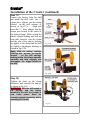
Crawler®
Installation of the Crawler (continued)
Step 9)
Install the Crawler drive unit to the
mounting
brackets
previously
installed on the scaffold. The vertical
CRAWLER logo should be facing
outward and centered left to right, as
shown in fig. #9A.
NOTE: The brackets only attach to
the outer tube. Allow 2½" of
clearance between the top of the
drive unit and the bottom of the
outer tube, as shown in fig. #9B.
NOTE: If the top of the bottom rung
on the scaffold is less than 11½"
above the floor surface, you must
move the bottom mounting bracket
to the second rung from the bottom
to
achieve
proper
clearance
between the drive unit and the outer
tube. If so, follow the steps in figs.
#6
relocating the lower mounting
bracket to the second rung from the
bottom..
Fig. #9A
Fig. #9B
Step 10)
Secure the Crawler drive unit to the
scaffold by installing the U-shaped
clamps over the outer tube and
bolting the clamps to the mounting
brackets using the four ½" X 1"
stainless steel cap screws previously
removed. Tighten the clamps to the
mounting brackets using the
⅜"Allen wrench supplied, as shown
in fig. #10. These brackets are now
secure on the Crawler and only need
to be moved if the Crawler is used
on a different brand and/or model of
scaffolding.
Fig. #10
Crawler®
Installation of the Crawler (continued)
Step 11)
Rotate the Crawler so the T-handle
height-selector pin is facing the
scaffold’s end frame, as shown in
fig. #11A. Remove the safety ring
pin from the height selector pin
assembly. Pull outward on the Thandle height-selector pin while
pushing the top flange of the
Crawler upward until the top flange
is even with, or above the top rung
of the scaffold, as shown in fig.
#11B. Confirm that the height
selector pin is locked and fully
inserted in one of the holes found in
the upper tube. Reinstall the safety
ring pin through the height selector
pin assembly, preventing the heightselector
pin
from
becoming
disengaged.
NOTE: Firmly hold the upper tube
and flange
height.
while
adjusting
Fig. #11A
the
Fig. #11B
Step 12)
Install the drill carriage to the top
flange of the Crawler, as shown in
fig. #12, using the bolts and Allen
wrench supplied (two ⅝" X ½"
button-head stainless steel bolts).
NOTE: The holes located in the top
flange are intentionally offset,
preventing the drill carriage from
being installed improperly by 180°.
Fig. #12
Crawler®
Installation of the Crawler (continued)
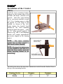
Step 13)
Using the charts below, locate the
brand and model # of drill you plan
to use and note the bushing number
in the column to the right. Locate
the bushing with the corresponding
number, from the bushings supplied.
The bushings are clearly marked
with an identifying number located
on the side of the bushing, as shown
in fig.#13A.
BUSHING #
#1
#2
#13614
#0614-20
#13618
#0617-20
#33618
#0624-20
#13624
#0627-20
#0724-20
#3
#4
#5
DC980
DS14DMR
SF180-A
DC983
DS18DMR
Fig. #13A
DC984
DC987
DC988
DC900KL
BDDF451
BHP451
EY6450
SF151-A
* Registered trademakes of identified companies
Insert the bushing into the clamp,
located on the drill carriage, making
certain the groove in the bushing
aligns properly with the pin found on
the rear of the clamp, as shown in fig
#13B.
NOTE: Make certain the continuous
split in the bushing, found 180°
from the groove, aligns with the split
in the front of the clamp.
Fig. #13B
Crawler®
Installation of the Crawler (continued)
Step14)
Make certain the clamp is
secured to the mounting plate in the
proper location, depending on the brand
of drill being used, as shown in
fig.#14A and the label below.
Fig. #14A
It may be necessary to relocate the
clamp to accommodate your brand of
drill. The clamp may be relocated by
removing the two Allen head mounting
screws using a 3/16” Allen wrench.
Move the clamp vertically to it's new
location and align the holes in the clamp
with the proper pre-drilled holes found
in the mounting plate. Reinstall the
mounting screw previously removed.
NOTE: When reinstalling the clamp to
the mounting plate, make certain the
clamp's mounting block is positioned
at the bottom of the clamp, as shown in
fig. # 14B.
Fig. #14B
Crawler®
Installation of the Crawler (continued)
Step 15)
Insert the hex end of the square
drive adapter (supplied) completely
into the chuck of the drill being
used, as shown in fig. #15
Fig. #15
NOTE: Make certain the drive
adapter is fully inserted into the
drill's chuck, leaving the ½" square
end of the
adapter projecting
approx. 2¼", as shown in fig. #15.
Step 16)
Move the speed selector switch to
the low or #1 speed position on the
drill and make certain the torque
setting is adjusted to the drill mode,
as shown in fig. #16.
WARNING:
All drills must be
installed into the drill carriage with
the low or #1 drill speed selected.
Any higher speed selected will allow
the scaffold to travel in excess of 1
ft. per second , possibly causing
injury and is not OSHA compliant.
Fig. #16
Crawler®
Installation of the Crawler (continued)
Step 17)
Remove the battery from the drill
and install the drill, with the ½"
square drive adapter, into the clamp
located on the drill carriage, as
shown in fig,#17A.
Align and
insert the ½" drive adapter into the
female port located in the center of
the bottom flange. Make certain the
plastic adapter bushing and drill are
both fully inserted into the clamp
and the rim of the adapter bushing
fits tightly to the clamp and the drill
fits tightly to the adapter bushing, as
shown in fig.#17B.
Note: With the battery removed
Fig. #17A
from the drill activate the throttle
located
on the drill carriage,
making certain the linkage operates
smoothly and fully engages and
disengages the trigger located on
the drill.
Fig. #17B
Step 18)
Tighten the knob on the clamp
clockwise and reinstall the battery,
as shown in fig. #18.
WARNING: With the drill locked in
the carriage and the battery
installed in the drill, the Crawler is
now under power. Read the
operating manual completely before
operating the Crawler.
Fig. #18
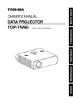
Crawler®
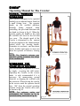
Operating Manual for The Crawler:
NORMAL FORWARD
OPERATION
The Crawler is designed to be operated
similarly to an outboard motor found on
a small fishing boat. The operator
stands on the scaffold platform,
normally
facing
forward,
while
controlling the speed and direction with
one hand, as shown in fig #1. When the
operator pushes the handle to the right
the scaffold will travel to the left and
vice versa. The desired speed of the
Crawler is determined by the amount
of pressure applied to the thumb throttle
located above the steering handle.
Remember to accelerate and decelerate
slowly. Sudden rapid starts or stops can
throw the operator off balance, causing
injury.
NOTE: The Crawler's extreme gear
reduction greatly increases the torque
of the cordless drill.
Fig. #1
OPERATING THE
CRAWLER IN REVERSE
The Crawler may be operated in reverse
by simply reversing the drill motor.
Operating the Crawler in the reverse
mode is only recommended if it is
necessary for maneuvering around
obstacles or aligning the scaffold with
the work area. When driving the crawler
in the reverse mode the operator should
turn 180° from the normal operating
position, facing the Crawler drive unit,
as shown in fig. #2.
NOTE: For optimum safety and
performance the Crawler is to be
operated mainly, as shown in Fig. #1.
Fig. #2
Crawler®
Operating Manual for The Crawler (continued)
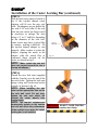
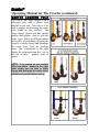
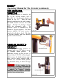
CASTER LOCKING POLE
The Crawler has been shipped with a
telescopic pole with a plastic boot
attached to one end. This pole is to be
used to engage and disengage the caster
locks found on your scaffold. The
“boot shaped” plastic tool has various
profiles and notches, used to grab the
brake levers found on different makes
and models of scaffolding, allowing the
operator to easily engage and disengage
the caster locks from the platform
above. The illustrations to the right
display the proper position and use of
the tool on three
popular styles of
casters.
NOTE: If the casters on your scaffold
differ from those shown to the right,
make certain you are able to easily
engage and disengage the caster locks,
with the tool provided before using
Crawler®
Operating Manual for The Crawler (continued)
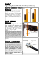
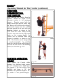
CASTER LOCKING POLE
STORAGE
The caster locking pole comes with a
metal hook attached to the end of the
pole, for easy storage. While the caster
locking pole is not in use it should be
stored by hanging it from the scaffold
frame or guard rail, as shown in fig. #3
ALLEN WRENCH
STORAGE
Fig. #3
The Crawler is shipped with a 3/8"
Allen wrench for the installation and
future adjustments. A plastic storage
clip has been provided and attached to
the underside of the upper mounting
bracket, as shown in fig. #4.
NOTE: If the Allen wrench storage clip
is located on the underside of the lower
mounting bracket, it may be relocated
to the upper bracket by removing the
center screw and attaching the clip to
the pre-drilled hole, found on the
underside of the upper mounting
bracket.
Fig. #4
CASTER LOCKING BAR
The caster locking bar is essential for
the safe operation of the Crawler drive
unit and should be checked regularly to
be sure the locking pins are fully
engaged above the rim of the top-hat
adapters, as shown in fig.# 5. If the bar
becomes disengaged, the operator will
no longer be able to steer the scaffold
properly, possibly causing injury to
operator or others.
Fig. #5
Crawler®
Operating Manual for The Crawler (continued)
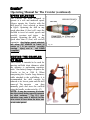
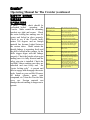
SPEED SELECTOR
The Crawler has been designed to
operate at a safe and moderate speed.
Always operate the Crawler with the
drill speed #1 (low) selected, as shown
in fig.#6. Operating the drill in any
speed other than #1 (low) will cause the
scaffold to travel at unsafe speeds and
possibly overturn and injure
the
operator. Operating the drill at any
speed other than #1 (low) will void all
warranties. Any higher speed selected,
will allow the scaffold to travel in
excess of 1 ft. per second , possibly
causing
injury and is
not OSHA
compliant.
Fig. #6
MOVING THE CRAWLER
BY HAND
The Crawler is intended to be used for
moving scaffolds short distances while
the operator is performing repetitive
tasks. One battery charge can power the
Crawler as far as 1500 ft. When
transporting the Crawler long distances
while attached to the scaffolding, it is
recommended the drill carriage be
reduced to its lowest point and the drill
removed. The operator
can then
manually push and steer the scaffold
using the handle, as shown in fig. #7)
NOTE: It may be necessary to elevate
the drive wheel during manual transport
on slick surfaces.
The 15:1 gear
reduction may make it difficult for the
drive wheel to turn when the drive unit
is not under power.
Fig. #7
Crawler®
Operating Manual for The Crawler (continued)
TELESCOPIC HEIGHT
ADJUSTMENT
Remove the safety ring pin from the Thandle height selector pin assembly.
While having a firm grip on the drill
carriage and upper tube assembly with
one hand, pull outward on the T- handle
selector pin with the other hand, as
shown in fig. #8A. The Crawler's upper
tube becomes disengaged from the lower
tube allowing the upper section to be
raised or lowered. This function allows
the Crawler to become telescopic and
adapt to various heights of scaffolding.
DANGER: Before pulling the height
selector pin, make certain you have a
firm hold on the upper tube and drill
carriage assembly, as shown in fig. #8A.
If the upper tube should fall, it could
cause serious injury to the operator.
Fig. #8A
After the proper height is achieved,
make certain the height selector pin
locates and is fully inserted in one of the
adjustment holes, located in the upper
tube. Reinstall the safety ring pin
through the height selector pin assembly,
as shown in fig.# 8B.With the height
selector pin fully inserted and the safety
ring pin reinstalled, the Crawler's
telescopic tubes are now locked and
ready for use.
DANGER: Never attempt to use the
Crawler without first inserting the safety
ring pin through the height selector pin
assembly.
This step is critical in
preventing the height selector pin from
accidentally
becoming
disengaged
causing the upper tube and drill
carriage to fall, potentially causing
serious injury to the operator or others.
Fig. #8B
Crawler®
Operating Manual for The Crawler (continued)
OPERATING THE
CRAWLER UNDER LOW
CLEARANCE CONDITIONS
While operating the Crawler, pay close
attention to obstacles overhead, as well
as any change in ceiling height. The
Crawler can compress to a total height
of 79", allowing it to pass through a
standard door opening. NEVER DRIVE
THE SCAFFOLD THROUGH A DOOR
OPENING OR LOW CLEARANCE AREA.
When encountering a door opening or
low clearance area, always dismount the
scaffold, remove the drill from the
carriage, and push the scaffold manually
until a safe and consistent operating
height is reached , as shown in fig. #9.
NOTE: It may be necessary to elevate
the drive wheel during manual transport
on slick surfaces.
The 15:1 gear
reduction may make it difficult for the
drive wheel to turn when the drive unit
is not under power.
THE FLOATING
WHEEL
Fig. #9
DRIVE
The Crawler's drive assembly is
connected only to the inner steering
column and floats independent of the
shorter outer tube (used to secure the
Crawler to the scaffold). This allows the
Crawler's drive assembly to
travel
vertically higher or lower than the
scaffold's casters, making it possible to
negotiate irregularities found on most
floor surfaces, or even travel over small
obstacles. It is imperative that a 2 ½"
clearance is maintained between the top
of the drive assembly and the outer tube,
as shown in fig. #10.
Fig. #10
Crawler®
Operating Manual for The Crawler (continued)
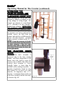
THE CRAWLER'S
THROTTLE
The Crawler's throttle is located at the
top of the steering handle and is
controlled by the operator's thumb, as
shown in fig. #11. With the drill
properly positioned in the drill carriage,
the thumb throttle activates the drill's
trigger through the linkage located
inside the rectangular tube.
The
Crawler's speed is controlled by the
amount of pressure applied. The more
pressure applied, the more power is
transfered to the drive wheel. Take time
to become familiar with the throttle's
operation and sensitivity.
Fig. #11
CRAWLER SAFETY &
SECURITY
The Crawler's mounting brackets are
equipped with two 3/8" holes to accept
an extended shank padlock
for
additional security on the job site, as
shown in fig. # 12A. The safety ring pin,
which secures the height selector pin in
place, can be easily replaced with a
common 3/8" extended shank padlock
for maximum safety, as shown in fig.#
12B
WARNING: If the crawler is left
Fig. #12A
unattended it is strongly recommended
that the safety ring pin be replaced with
a padlock to prevent someone
unfamiliar with the Crawler's telescopic
function from serious injury.
Fig. #12B
Crawler®
Operating Manual for The Crawler (continued)
REMOVING
&TRANSPORTING
THE CRAWLER
When removing the Crawler from the
scaffold
shorten the length of the
telescopic portion to the minimum
distance.
Properly secure both the
height selector pin and the safety ring
pin. Remove the drill from the carriage.
Loosen both clamps from the scaffold
and push upward on the outer tube and
mounting bracket, as shown in fig.
#13A. With one hand firmly on the
Crawler's outer tube and the other hand
firmly on the steering handle, the
Crawler can be wheeled from one
location to another, as shown in fig.
#13B. The Crawler can be transported
or stored horizontally
by carefully
laying the Crawler down and allowing it
to rest on the back side of the mounting
brackets, as shown in fig. #13C.
MAXIMUM OPERATING
HEIGHT
Never operate the Crawler while
standing at a platform height greater
than a 2:1 height-to-base width ratio.
For example, if the base width of the
scaffold's end frame is 30", the
maximum safe platform height is 60"
(i.e., width x 2 = max. platform height).
Fig. #13A
Fig. #13B
Fig. #13C
Crawler®
Operating Manual for The Crawler (continued)
ADDING ADDITIONAL
PIN SELECTOR HOLES
Additional holes may be added between
the pre-drilled holes, located in the
upper tube, in order to
achieve
additional
operating
height
requirements. The location for these
additional holes can be located by
moving the drill carriage vertically to
the desired height. While holding the
drill carriage at the desired height
wrap a piece of masking tape around
the perimeter of the upper tube at the
lowest visible point possible and even
with the top of the middle tube, as
shown in fig.#14A. Fully extend the
upper tube and drill carriage. Lock the
tubes together using the height selector
pin, as outlined in the “TELESCOPIC
HEIGHT ADJUSTMENT” section of this
manual. With the tubes locked together,
locate and mark the position of the new
hole by measuring down 1 ½" from the
bottom of the masking tape in line with
the existing pre-drilled holes using a
framing square, as shown in fig. #14B.
Center punch and drill a 3/8" hole
through the upper tube at the mark
previously located.
Fig. #14A
NOTE: Be
extremely careful when
drilling through the upper tube not to
drill into or damage the internal drive
shaft assembly.
NOTE: Make sure to allow at least 3/4"
between the new hole and the existing
pre-drilled holes in the upper tube.
Fig.#14B
Crawler®
Operating Manual for The Crawler (continued)
THE CRAWLER'S
TORQUE & AUTO BRAKE
The Crawler acquires its unbelievable
torque by drastically reducing the gear
ratio of an already powerful cordless
drill. Through
gear reduction, the
Crawler reduces the speed of the drill by
a ratio of 15:1 thereby increasing the
torque of the drill fifteen times. The
same principle applies for stopping the
Crawler. The auto brake on the drill is
amplified fifteen times through the
same gear reduction system. The
Crawler will come to a complete stop as
soon the unit is no longer under power.
It's still necessary and mandatory that
all casters are locked when the unit is
not under power.
NOTE: Lock all casters using the
CASTER LOCKING POLE
before
climbing on or off the scaffold, as soon
as the scaffold comes to a complete
stop and before any work begins.
TIRE PRESSURE
The Crawler uses an 8” pneumatic nonmarking tire, and should be inflated to a
maximum of 50 psi. for normal use.
Additional traction may be needed when
operating the Crawler on slick or
smooth concrete surfaces. This can be
achieved by reducing the tire pressure.
By reducing the tire pressure, friction is
added and may result in a temporary
decrease in battery life. Remember to
inflate the tire to the normal operating
psi. when the conditions return to
normal.
Crawler®
Operating Manual for The Crawler (continued
SAFETY CHECK
BEFORE
OPERATING
A daily
safety check should be
performed before
operating
the
Crawler. Make certain the mounting
brackets are tight and secure. Check
the caster locking bar making sure it's
secure and locked in place properly.
Check to see if the Crawler easily
rotates 360 degrees and no foreign
material has become lodged between
the various tubes. Make certain the
throttle linkage is operating freely and
the drill is locked in the carriage so the
drill's trigger aligns with the linkage
properly. Check the height selector pin
making sure it is fully inserted and the
safety ring pin is installed. Check the
scaffold's casters making sure they are
unlocked and turn freely and the
“caster locking pole” is present and
able to engage and disengage the caster
locks found on your scaffold. Remove
all debris (plaster, paint, joint
compound, etc.) from the Crawler after
every use. Foreign material can
damage the unit making it dangerous to
operate.
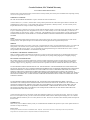
Mounting brackets
Make sure they are tight & secure.
Caster locking bar
Make sure it's in place & the lock
pins are fully engaged.
Steering
Rotate the top handle making sure
the Crawler can rotate 360°
Linkage
Check to see if it moves freely.
Drill
Make sure the drill is positioned in
the carriage so the linkage aligns
properly with the drill's trigger.
Drill clamp
Make sure the clamp is snug & the
drill is secure.
Height selector pin
Make sure the pin is fully inserted
through both tubes and that the
tubes are securely locked together.
Make certain the safety ring pin is
inserted through the height selector
pin assembly at all times.
Make sure it is present and able to
engage and disengage the caster
locks found on your scaffold.
If left unattended, make certain a
padlock is placed through the height
selector pin assembly.
Safety ring pin.
Caster locking pole
Padlock
Crawler Products, LLC Limited Warranty
For Crawler Products and Accessories
Welcome to the Crawler Products Family! Please read this warranty carefully and consult your User Manual before requesting warranty
service to avoid a possible service call.
WARRANTY COVERAGE
This ONE YEAR LIMITED WARRANTY on parts is limited to the terms set forth below:
Crawler Products, LLC (“Crawler”) warrants those Crawler products purchased in the United States against defects in materials and
workmanship for a period of one (1) year from the date of original retail purchase ("Warranty Period"). To ensure warranty service,
keep the dated bill or sale receipt as evidence of the purchase date.
If a defect arises and a valid claim is received by Crawler within the Warranty Period, Crawler will provide, when needed, service labor
to repair a manufacturing defect at its designated Service Center. To obtain warranty service in the United States, you must call our
Customer Support at 1.866.572.8297, 9:00am – 5:00pm CST. The determination of service will be made by Crawler Customer Support.
PLEASE DO NOT RETURN YOUR PRODUCT TO CRAWLER WITHOUT PRIOR AUTHORIZATION AND REPAIR MEMO
NUMBER.
PARTS
New or remanufactured replacements for defective parts will be used for repairs by Crawler at its designated Service Center for the
Warranty Period. Such replacement parts are warranted for the remaining portion of the original Warranty Period.
SERVICE
During the Warranty Period, at its option, Crawler will (1) repair the defective part(s), (2) replace the defective part(s), or (3) replace the
entire product. The customer will be required to ship the product to the Service Center indicated at the time Customer Service is
contacted to make the necessary repairs. You are responsible for all transportation charges to and from the Service Center. Crawler is
not responsible for the de-installation or re-installation of the product.
PACKAGING AND SHIPPING INSTRUCTIONS
When you send the product to the authorized Crawler Service Center you must use the original cart, box and packaging material or an
equivalent as approved by Crawler. Crawler accepts no responsibility for any damage during shipping due to improper packaging.
EXCLUSIONS AND LIMITATIONS
This warranty does not cover defects, malfunctions or failures resulting from shipping or transit accidents, abuse, misuse, operation
contrary to furnished instructions operation on incorrect power supplies, operation with faulty associated equipment, modification,
alteration, improper servicing, tampering or normal wear and tear or products which the serial number has been removed or defaced.
TO THE MAXIMUM EXTENT PERMITTED BY LAW, THIS WARRANTY AND THE REMEDIES SET FORTH ABOVE ARE
EXCLUSIVE AND IN LIEU OF ALL OTHER WARRANTIES, REMEDIES AND CONDITIONS, WHETHER ORAL OR WRITTEN,
EXPRESS OR IMPLIED. CRAWLER SPECIFICALLY DISCLAIMS ANY AND ALL IMPLIED WARRANTIES, INCLUDING,
WITHOUT LIMITATION, WARRANTIES OF MERCHANTABILITY AND FITNESS FOR A PARTICULAR PURPOSE. IF
CRAWLER CANNOT LAWFULLY DISCLAIM OR EXCLUDE IMPLIED WARRANTIES UNDER APPLICABLE LAW, THEN TO
THE EXTENT POSSIBLE ANY CLAIMS UNDER SUCH IMPLIED WARRANTIES SHALL EXPIRE ON EXPIRATION OF THE
WARRANTY PERIOD.
TO THE MAXIMUM EXTENT PERMITTED BY LAW, CRAWLER IS NOT RESPONSIBLE FOR DIRECT, SPECIAL,
INCIDENTAL OR CONSEQUENTIAL DAMAGES RESULTING FROM ANY BREACH OF WARRANTY OR CONDITION, OR
UNDER ANY OTHER LEGAL THEORY, INCLUDING, BUT NOT LIMITED TO, LOST PROFITS, DOWN TIME, AND ANY
DAMAGE TO OR REPLACEMENT OF EQUIPMENT AND PROPERTY. SOME JURISDICTIONS DO NOT ALLOW THE
EXCLUSION OR LIMITATION OF INCIDENTAL OR CONEQUENTIAL DAMAGES, SO THE ABOVE LIMITATIONS OR
EXCLUSIONS MAY NOT APPLY TO YOU.
Crawler retains the right to assess all warranty claims and to determine if damages are covered by the warranty. In the case of a claim
that is not covered by the warranty you will be contacted to determine whether Crawler should repair the damages for a fee or whether
the product should be returned to you as received by the Service Center. There are no warranties which extend beyond the description on
the face hereof.
USER MANUAL
Please review your User Manual carefully so that you will understand the installation and operation of your Crawler product and how to
maximize its safety and efficiency.
WARRANTY SERVICE
For warranty service information contact Crawler at 1.866.572.8297, 9:00am – 5:00pm CST. Parts and service labor that are the responsibility of Crawler will be provided without
charge. Other service is at customer’s expense. You must provide the model, serial number and purchase date.