1
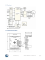
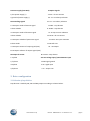
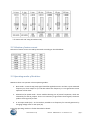
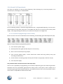
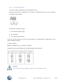
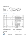
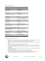
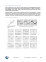
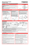
SMC64 WP v2 Manual SMC64 WP v2 – programmable driver for 2-phase bipolar motors P.P.H. WObit E.K.J. Ober s.c. Dęborzyce 16, 62-045 Pniewy tel. 48 61 22 27 422, fax. 48 61 22 27 439 e-mail: [email protected] www.wobit.com.pl Contains 1.Safety and assembly rules .................................................................................................................................... 3 1.1.Safety rules ................................................................................................................................................... 3 1.2 Assembly recommendation .......................................................................................................................... 3 2.Main characteristic of the driver .......................................................................................................................... 3 2.1Features: ........................................................................................................................................................ 3 2.2. Power supply ............................................................................................................................................... 4 2.3. Connection with a motor ............................................................................................................................. 4 2.3. Flowchart ..................................................................................................................................................... 5 2.4. Connectors description ................................................................................................................................ 5 3. Driver configuration ............................................................................................................................................ 6 3.1 Selection of step division .............................................................................................................................. 6 3.2. Selection of motor current .......................................................................................................................... 7 3.3. Operating modes of the driver .................................................................................................................... 7 3.3.1.Selected V1/V2 speed mode ................................................................................................................. 8 3.4 Scheme of controlling signals inputs .......................................................................................................... 10 3.5Table of operating parameters of the driver ............................................................................................... 10 4.Technical data .................................................................................................................................................... 11 5.Main exploitation rules ...................................................................................................................................... 11 6.Complementary information ............................................................................................................................. 12 Thank you for selecting our product! This instruction will help you at correct service and accurate exploitation of described device. Information included in this instruction were prepared with high attention by our specialists and is description of the product. Based on the information should not be inferred a certain features or suitability for a particular application. This information does not release the user from the obligation of own judgment and verification. P.P.H. WObit E.K.J. Ober S.C. reserves the right to make changes without prior notice. Please read instructions below carefully and adhere to its recommendation Please pay special attention to the following characters: CAUTION! Not adhere to instruction can cause damage or impede the use of hardware or software. www.wobit.com.pl Manual -SMC64 WP v2 – 27.10.2014 – v.1.1 page 2 1.Safety and assembly rules 1.1.Safety rules Prior to first start-up of the device please refer to this manual; Prior to first start-up of the device please make sure all cables are correctly connected, Provide appropriate working conditions, in compliance with the device specifications (e.g.: power supply voltage, temperature, maximum current consumption). Before making any modifications to wiring connections, disconnect the power supply voltage. 1.2 Assembly recommendation In environments with unknown noise levels, it is recommended to follow measures described below to prevent any possible interruptions of the device operation: Ground or reset metal rails, on which are mounted instruments, Do not power devices on the same line as the device without a corresponding high power line filters; Please use screening of the supply, sensor and signal cables, with the ground for the screen should be connected only on one side, as close to the device; For motor power supply please use twisted pair cables, and if possible use a ferrite bead assumed on the wire; Please avoid of leading control cables (Signal) parallel or in close to electrical and power wires; Please avoid proximity to devices that generate high levels of electromagnetic interferences and/or pulse (high-power loads, the burden of the phase or power control group). 2.Main characteristic of the driver Miniature SMC64v2 driver is designed for use with 2-phase stepper motor with bipolar winding (8 or 4 wires) or unipolar 6-wires used as bipolar. It enables controlling with full step or step division on 2/4/5/8/10 or 16 parts. Rated current of motor is set by miniature switches in range of 1,2 – 3,5A. At decreased current consumption mode (up to 50%) occurs fading of clock pulses (automatically reduction after 0,5 sec). SMC64v2 driver has active cooling as radiator with cooler (C) and is designed for mounting on a mounting rail. For installation in the device is provided version(B) with the angular radiator with aluminum sheet (2mm thickness). The controller has built-in generator, which allows programming of two motor velocities. Additionally jumper allows for turn on function “SOFTSTART”, which gently accelerate motor up to selected velocity. 2.1Features: microprocessor, integrated power stages for 2-phase bipolar motors, Thermal, voltage and short –circuit protection (partly, do not protect against short-circuit for power supply an between phases), High rated current 3,5A (4A temp) www.wobit.com.pl Manual -SMC64 WP v2 – 27.10.2014 – v.1.1 page 3 Full, half step and microstep operation (1/4, 1/5, 1/8, 1/10, 1/16), Two programmable timing frequency, Soft start and return function, Analog input 0-5V for generate velocity, Opto- isolated output and input signals, Severable automatic current reduction, Power supply, signals for motor and controlling on separable rails Combicon type. 2.2. Power supply The driver must be supply from source with proper output voltage (max. 40V) and current efficiency. The feeder also must receive motor braking energy, which is provided by initial capacitors with capacity at least 4700µF. It is recommended to use (dedicated for drivers) ZN100 feeder for small motors and ZN200 feeder for large motors. CAUTION! Do not exceed maximal power supply of the driver, it can cause its damage. 2.3. Connection with a motor To minimize disturbance caused by way of drivers work (current regulation by width, filling) cables, which derivate signals to motor phases should be twist in pairs (A with /A, B with /B). Additionally it is recommended to mount a ferrite bead on a cable. www.wobit.com.pl Manual -SMC64 WP v2 – 27.10.2014 – v.1.1 page 4 2.3. Flowchart 2.4. Connectors description www.wobit.com.pl Manual -SMC64 WP v2 – 27.10.2014 – v.1.1 page 5 J1 Power supply (max.40V) J3 Option signals 1 plus power supply (+) 1-2 NC – do not connect 2 ground of power supply (-) 3-4 V2 –V2 velocity selection J2 Controlling signals 5-6 V1 – V1 velocity selection 1 transoptor anode of execute signal 2 ditto cathode 7-8 M2 – step division 9-10 M1 – step division 3 transoptor anode of direction signal 4 ditto cathode 11-12 stop current reduction 13-14 NC- do not connect 5 transoptor cathode of permission signal 6 ditto anode 15-16 An- Ain input activation 17-18 Soft start 7 transoptor emitter of output signal (OUT) 19- +5V output 8 transoptor collector of output signal (OUT) J4 Output for motor J5 1-2 M3 – step division 1 A phase J6 0..5V voltage input/ potentiometer input 2 /A phase 1 GND signal ground 3 B phase 2 Ain signal input 4 /B phase 3 +5 – output +5V 3. Driver configuration 3.1 Selection of step division Step division is made by M1, M2 and M3 jumpers according to scheme below: www.wobit.com.pl Manual -SMC64 WP v2 – 27.10.2014 – v.1.1 page 6 * for motor with 1.8 step (in brackets 0.9) 3.2. Selection of motor current Selection of motor current is made by SW switch according to the table below: 3.3. Operating modes of the driver SMC64 v2 driver can operate in three operating modes: 1. Basic mode – external step (CLK) signal should be applied into CLK+ and CLK- inputs. Maximal frequency on driver output is up to 60 kHz. Above this frequency it is not guarantee correct operation of the driver. 2. Selected V1/V2 speed mode – driver enables selecting one of preset frequencies, which are selected by V1 and V2 jumpers. Then is not necessary to give external CLK signals, the driver produce clock signal by its own. 3. 0…5V intput mode (Ain) – at this mode is possible to set frequency for internal generator by changing voltage value on Ain input (J6). Particular operating modes are further described in details. www.wobit.com.pl Manual -SMC64 WP v2 – 27.10.2014 – v.1.1 page 7 3.3.1.Selected V1/V2 speed mode The driver can operate in constant timing frequency, after selecting it by V1 and V2 jumpers on J3 connector pin, according to a scheme below: Prior to selecting velocity it should be programmed at first. Programmed frequency is store at nonvolatile memory of the driver, due this it is accessible also after turn on and turn off of driver power supply. After programming the velocity is set, when on CLK input is set a high state. 3.3.1.1. Procedure of programming V1 and V2 velocity Both to V1 and to V2 can be subordinate one of following, automatically generated frequencies (Hz): Order of V1 (V2) frequency programming actions: 1) Turn off driver power supply 2) Give EN permission signal (5 and 6 clamps of J2 connector), 3) Short -circuit V1 and V2 pins by jumpers, 4) Turn on driver power supply – motor should start rotate with rising velocity every 0,5s according to table above, 5) At the moment of reaching proper velocity took off the V1 (V2) jumper, and then V2 (V1) 6) Turn off power supply. The procedure above assume non active clock input (CLK) There is also a possibility of programming as V1 and V2 frequencies given from external generator. Therefore turn off a permission signal (EN non active), and on CLK input (1 and 2 clamps of J2 connector) give signal with required frequency, and made all actions from 4 to 6 of procedure above. In this case it is impossible to observe motor work. www.wobit.com.pl Manual -SMC64 WP v2 – 27.10.2014 – v.1.1 page 8 3.3.2. 0…5V intput mode (Ain) This mode enables setting velocity by analog input Ain (J6). Analog signal should be connected to J6 connector. A potentiometer also can be connected, according to picture below. Procedure of activation Ain input: 1) Turn off driver power supply 2) Put AN jumper 3) Turn of driver power supply From this moment frequency of driver internal generator is proportional to voltage given on Ain input according to formula: Fgen(Hz)=Ain*204,8 Where for voltage <0,1V Fgen =0 (motor is stopped) Additionally by V1 and V2 jumpers can be calibrated generator frequency. CAUTION! On Ain input can be given voltage from range 0..5V. Do not exceed this range. www.wobit.com.pl Manual -SMC64 WP v2 – 27.10.2014 – v.1.1 page 9 3.4 Scheme of controlling signals inputs CLK, DIR, ENABLE inputs and OUT output are opto-isolated. Controlling signals should be connected according to scheme below: 3.5Table of operating parameters of the driver Description: For STEP, EN, DIRECTION columns: 0 – no signal (0V) 1 – signal at low level (+5V) 010101- generated signal 0 1 give signal 1 0 signal decline www.wobit.com.pl For J3-V1, J3-V2, Soft start, AN columns: 0 – pin open 1 – pin closed 0 1 pins are open during operation of the device Manual -SMC64 WP v2 – 27.10.2014 – v.1.1 page 10 4.Technical data Type SMC 64WP V2 Power supply DC 18 up to 36V Phase current 1,2 -3,5 A Set current DIP SWITCH Automatic current reduction Yes, up to 50% Type of work Bipolar Step division 1, ½, ¼, 1/5, 1/8, 1/10, 1/16 Step frequency 0-16 kHz Input signals TTL, CMOS Optically isolation For inputs and outputs Input signals current 15mA Operation temperature range 0-40C Motor connection Pluggable terminal block Signals connection Pluggable terminal block Dimensions 56*102*52mm Way of mounting Handle for DIN35 rail 5.Main exploitation rules Application of described device at special importance systems (e.g. medical systems, machines, etc.) requires using additional protection against working errors. Device must be correctly mounted in panel. Not following to the rules can cause electric shock. Do not connect external devices if the device is turned on. Do not disassemble and make modifications to the device. If necessary, please contact us. Unauthorized alterations may result in electric shock or cause a fire. This causes in its invalidation. This devices can’t be exploited outside. It may result in electric shock and shorten expected life time of the device. External power supply connections should be made by ZOAWG cables. Exceeding recommended operating parameters can lead to damage of the device or fire. For cleaning the device do not use cleaning products containing water or oils. www.wobit.com.pl Manual -SMC64 WP v2 – 27.10.2014 – v.1.1 page 11 6.Complementary information High controlling currents along with motor winding inductivity cause damaging resonances distort current waveform and negatively influence on motor moving linearity. It is especially troublesome at higher velocities. Typical drivers usually do not keep up current changes at windings causing significant distortions of its waveform. SMC64 driver allows to major reduction of this effects due built-in, advanced modes for controlling current value (so called fast and mixed modes), which keep up its changes at velocity and step division functions. At pictures below are presented current waveforms of windings with applying mentioned modes against distorted waveforms due controlling at typical mode (so called slow), for different velocities and step divisions. www.wobit.com.pl Manual -SMC64 WP v2 – 27.10.2014 – v.1.1 page 12