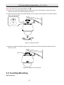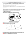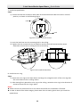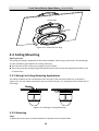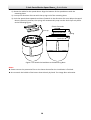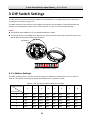
1
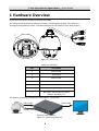
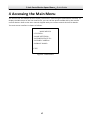
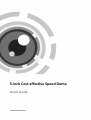
5-inch Cost-effective Speed Dome Quick Guide UD.6L0201B1044A02 5-inch Cost-effective Speed Dome·Quick Guide Thank you for purchasing our product. If there are any questions, or requests, please do not hesitate to contact the dealer. This manual applies to 5-inch cost-effective speed dome. This manual may contain several technical incorrect places or printing errors, and the content is subject to change without notice. The updates will be added to the new version of this manual. We will readily improve or update the products or procedures described in the manual. DISCLAIMER STATEMENT “Underwriters Laboratories Inc. (“UL”) has not tested the performance or reliability of the security or signaling aspects of this product. UL has only tested for fire, shock or casualty hazards as outlined in UL’s Standard(s) for Safety, UL60950-1. UL Certification does not cover the performance or reliability of the security or signaling aspects of this product. UL MAKES NO REPRESENTATIONS, WARRANTIES OR CERTIFICATIONS WHATSOEVER REGARDING THE PERFORMANCE OR RELIABILITY OF ANY SECURITY OR SIGNALING RELATED FUNCTIONS OF THIS PRODUCT.” 0100011030402 1 5-inch Cost-effective Speed Dome·Quick Guide Regulatory Information FCC Information FCC compliance: This equipment has been tested and found to comply with the limits for a digital device, pursuant to part 15 of the FCC Rules. These limits are designed to provide reasonable protection against harmful interference when the equipment is operated in a commercial environment. This equipment generates, uses, and can radiate radio frequency energy and, if not installed and used in accordance with the instruction manual, may cause harmful interference to radio communications. Operation of this equipment in a residential area is likely to cause harmful interference in which case the user will be required to correct the interference at his own expense. FCC Conditions This device complies with part 15 of the FCC Rules. Operation is subject to the following two conditions: 1. This device may not cause harmful interference. 2. This device must accept any interference received, including interference that may cause undesired operation EU Conformity Statement This product and - if applicable - the supplied accessories too are marked with "CE" and comply therefore with the applicable harmonized European standards listed under the Low Voltage Directive 2006/95/EC, the EMC Directive 2004/108/EC, the RoHS Directive 2011/65/EU. 2012/19/EU (WEEE directive): Products marked with this symbol cannot be disposed of as unsorted municipal waste in the European Union. For proper recycling, return this product to your local supplier upon the purchase of equivalent new equipment, or dispose of it at designated collection points. For more information see: www.recyclethis.info. 2006/66/EC (battery directive): This product contains a battery that cannot be disposed of as unsorted municipal waste in the European Union. See the product documentation for specific battery information. The battery is marked with this symbol, which may include lettering to indicate cadmium (Cd), lead (Pb), or mercury (Hg). For proper recycling, return the battery to your supplier or to a designated collection point. For more information see: www.recyclethis.info. 2 5-inch Cost-effective Speed Dome·Quick Guide Safety Instruction These instructions are intended to ensure that user can use the product correctly to avoid danger or property loss. The precaution measure is divided into “Warnings” and “Cautions” Warnings: Serious injury or death may occur if any of the warnings are neglected. Cautions:Injury or equipment damage may occur if any of the cautions are neglected. Warnings Follow these safeguards to prevent serious injury or death. Cautions Follow these precautions to prevent potential injury or material damage. Warnings All the electronic operation should be strictly compliance with the electrical safety regulations, fire prevention regulations and other related regulations in your local region. Please use the power adapter, which is provided by normal company. The standard of the power adapter is 24VAC10% or 12VDC10% (depending on models). The power consumption cannot be less than the required value. Do not connect several devices to one power adapter as adapter overload may cause over-heat or fire hazard. Please make sure that the power has been disconnected before you wire, install or dismantle the speed dome. When the product is installed on wall or ceiling, the device shall be firmly fixed. If smoke, odors or noise rise from the device, turn off the power at once and unplug the power cable, and then please contact the service center. If the product does not work properly, please contact your dealer or the nearest service center. Never attempt to disassemble the speed dome yourself. (We shall not assume any responsibility for problems caused by unauthorized repair or maintenance.) Cautions Do not drop the dome or subject it to physical shock, and do not expose it to high electromagnetism radiation. Avoid the equipment installation on vibrations surface or places subject to shock (ignorance can cause equipment damage). Do not place the dome in extremely hot, cold, dusty or damp locations, otherwise fire or electrical shock will occur. The operating temperature should be -30°C ~ 65°C(outdoor speed dome) and -10°C ~ 50°C (indoor speed dome). The dome cover for indoor use shall be kept from rain and moisture. Exposing the equipment to direct sun light, low ventilation or heat source such as heater or radiator is forbidden (ignorance can cause fire danger). 3 5-inch Cost-effective Speed Dome·Quick Guide Do not aim the speed dome at the sun or extra bright places. A blooming or smear may occur otherwise (which is not a malfunction however), and affecting the endurance of sensor at the same time. Please use the provided glove when open up the dome cover, avoid direct contact with the dome cover, because the acidic sweat of the fingers may erode the surface coating of the dome cover. Please use a soft and dry cloth when clean inside and outside surfaces of the dome cover, do not use alkaline detergents. Please keep all wrappers after unpack them for future use. In case of any failure occurred, you need to return the speed dome to the factory with the original wrapper.Transportation without the original wrapper may result in damage on the speed dome and lead to additional costs. 4 5-inch Cost-effective Speed Dome·Quick Guide Table of Contents 1 Hardware Overview ..................................................................................... 6 2 Installation ................................................................................................... 7 2.1 Wall Mounting.................................................................................................................................. 7 2.2 In-ceiling Mounting .......................................................................................................................... 9 2.3 Ceiling Mounting ............................................................................................................................ 12 2.3.1 Wiring For Ceiling Mounting Applications ............................................................................ 12 2.3.2 Mounting................................................................................................................................. 12 3 DIP Switch Settings ..................................................................................... 15 3.1.1 Address Settings ..................................................................................................................... 15 3.1.2 Baudrate Settings ................................................................................................................... 16 4 Accessing the Main Menu .......................................................................... 17 5 5-inch Cost-effective Speed Dome·Quick Guide 1 Hardware Overview Please turn the power off before connect the cables. The cable interfaces of speed dome are shown in following figure(right). The cables are distinguished by different colors. The labels attached on the cables are for identification. CK BLA D RE 1 2 3 LL YE V 24 N AC EE V R /G C24 OW A 4 5 VIDEO ORANGE RS485 + YELLOW RS485 - 7 Figure 1-1 Overview Table 1-1 Overview No. Description 1 Power cable 2 Grounding 3 Power cable 4 RS-485 cable 5 RS-485 cable 6 Video cable 7 DIP switch for settings the dome address, baudrate, etc. The typical connecting system of the speed dome is as follows: Video Cable Video Cable RS-485 Cable Speed Dome Remote Control Device Figure 1-2 Connecting Diagram 6 Monitor 6 5-inch Cost-effective Speed Dome·Quick Guide 2 Installation Before you start: Check the package contents and make sure that the device in the package is in good condition and all the assembly parts are included. There are several ways to install the analog speed dome. The wall mounting is taken as an example below. 2.1 Wall Mounting Steps: 1. Loosen the two lock screws as shown in the following figure. 2. Remove the lower dome. Back Box Lock Screw Lock Screw Lower Dome Figure 2-1 Disassemble the Speed Dome 3. Remove the protective lens cover,foam and sticker as shown in the following figure. 4. Set the address andbaudrate for the speed dome. Please refer to the Section 3 DIP Switch Settings for DIP switch settings. 5. Install the lower dome back and tighten the two lock screws. Protective sticker protectivefoam 7 5-inch Cost-effective Speed Dome·Quick Guide Figure 2-2 Disassemble the Speed Dome 6. Drill four M8 screw holes on the wall according to the screw holes of the wall mount. 7. Secure the wall mount to the wall with screws. Notes: For cement wall mounting, you need to use the expansion screw to fix the mount. The mounting hole of the expansion pipe on the wall should align with the mounting hole on the mount. For wooden wall mounting, you can just use the self-tapping screw to fix the bracket. Please make sure that the wall is strong enough to withstand more than 8 times the weight of the dome and the mount. Nuts and Washers Expansion Screws Figure 2-3 Install the Wall Mount 8. Wrap the threadpart with the threadtape and rotate the pendant adapter to the wall mount. 9. Secure the pendant adapterto the wall mount with a set screwas shown in Figure 2-4. 10. Loosen the lock screws of the adapter. ② ① Top View of Pendant Adapter Pendant Adapter Lock Screw Lock Screw Figure 2-4 Install the Pendant Adapter 8 5-inch Cost-effective Speed Dome·Quick Guide 1 Note: The dimension of pendant adapter is G1 . 2 11. Hook the two ends of thesafety rope to theback box of the speed dome and the wall mount respectively. Route the cables through the mount. 12. Align the direction label of pendant adapter with the label of the back box to install the speed dome as shown below. ② ① ③ ④ Figure 2-5 Align the Labels 13. Rotate the back boxclockwise tightly. Secure the back box and the pendant adapter with the two lock screws. Lock Screw Figure 2-6 Tighten the Lock Screws 2.2 In-ceiling Mounting Before you start: 9 5-inch Cost-effective Speed Dome·Quick Guide The in-ceiling mounting is applicable to the indoor ceiling construction. The followings are the mandatory precondition for mounting: The height of the space above the ceiling must be more than 250mm. The thickness of the ceiling must ranges from 5 to 40mm. The ceiling must be strong enough to withstand more than 4 times the weight of the dome and its accessories. Steps: 1. Rotate the lower dome counterclockwise to separate it from the back box as shown in Figure 2-7. 2. Remove the protective lens cover, foam and sticker from the dome drive. 3. Set the address and baudrate for the speed dome. Please refer to the Section 3 DIP Switch Settings for DIP switch settings. 4. Attach lower dome to the back box, and rotate clockwise to secure it. Foam Back Box Lower Dome Sticker Figure 2-7 Remove the Protective Accessory 5. Drill a hole on the ceiling according to the drill template (supplied). Note: ±2mm of the diameter of the circle is tolerable. Φ 224 Figure 2-8 Draw and Cut Hole on the Ceiling 6. Connect the cables. The video cable, control wire and network cable have been connected to the corresponding interfaces. Connect the power cable and the red LED indicator turns on when the power is on. Note: Please turn the power off after checking the speed dome. 10 5-inch Cost-effective Speed Dome·Quick Guide 7. Install the speed dome. Steps: 1). Loosen the two lock screws on both sides of the back box and make the locks in internal position, as shown in the following figure: Lock Lock Figure 2-9 Locks and Lock Screws 2). Push the back box into the mounting hole in the ceiling. 3). Tighten the lock screws with the screwdriver and the locks will automatically rotate outwards to secure the in-ceiling mount to the ceiling. Ceiling Lock Lock Figure 2-10 Install the back box 8. Install the trim ring. Steps: 1). Attach the trim ring to the lower dome and align the triangular notch of the trim ring with the arrow label on the in-ceiling mount. 2). After having firmly placed the trim ring to the ceiling, rotate the trim ring in the direction of arrow to secure the trim ring in place. Notes: Please remove the protective film on the lower dome after the installation is finished. In order to obtain clear video images, please wear the anti-static gloves when you install the speed dome. 11 5-inch Cost-effective Speed Dome·Quick Guide Arrow label Notch Figure 2-11 Install the Trim Ring 2.3 Ceiling Mounting Before you start: The ceiling mounting is applicable to the indoor/outdoor solid ceiling construction. The followings are the mandatory precondition for ceiling mounting: The thickness of the ceiling must ranges from 5 to 40mm. The ceiling must be strong enough to withstand more than 4 times the weight of the dome and its accessories. 2.3.1 Wiring For Ceiling Mounting Applications The cables of dome can be routed either from the top or the side of the back box, as shown in Figure 2-12. For the cables routed from the top of the back box, it is required to drill a cable hole in the ceiling. Figure 2-12 Cabling for Ceiling Mounting 2.3.2 Mounting Steps: 1. Rotate the lower dome counterclockwise to separate it from the back box. 12 5-inch Cost-effective Speed Dome·Quick Guide 2. Remove the protective lens cover, foam and sticker from the dome drive. Foam Back Box Lower Dome Sticker Figure 2-13 Remove the Protective Accessory 3. Set the address and baudrate for the speed dome. Please refer to the Section 3 DIP Switch Settings for DIP switch settings. 4. Attach lower dome to the back box, and rotate clockwise to secure it. 5. Use the mounting base as a template to mark four screw holes onto the ceiling. 6. If you route cables from the top of the back box, mark the cable hole on the ceiling and drill a hole. 7. Secure the mounting base to the ceiling with set screws. Screw Holes Cable Hole Figure 2-14 Mark the Screw Positions If the speed dome is installed to the wooden wall, use the self-tapping screws to secure the mounting base. If the dome is installed to the cement wall, drill three Φ5 mounting holes onto the wall according to the hole locations, and then insert the cement screws into the holes and finally use self-tapping screws to secure the mounting base to the wall. 8. Install the speed dome to the mounting base. Steps: 13 5-inch Cost-effective Speed Dome·Quick Guide 1). Route the cables for the speed dome. Align the bottom of the speed dome with the mounting base. 2). Line up the direction of arrow with the spring end of the mounting base. 3). Push the speed dome upwards and then forwards in the direction of arrow. When the speed dome is placed in position, the spring will automatically snap into the lock clip firmly. Refer to the following figure. Push forwards Line up Push upwards Spring Lock clip Figure 2-15 Attach the Back Box to the Mounting Base Notes: Please remove the protective film on the lower dome after the installation is finished. Do not touch the bubble of the lower dome directly by hand. The image blurs otherwise. 14 5-inch Cost-effective Speed Dome·Quick Guide 3 DIP Switch Settings The DIP switchis used for setting the address and baudrate for the speed dome,with value ON=1 and OFF=0, as shown in Figure 3-1. The SW1 switches from the first to the eighth are used to set the address. The SW2 switches are used to set the baudrate. Please refer to the section 3.1.1 and 3.1.2 for detailed settings. Notes: The default dome address is 0. The default baudrate is 2400. The speed dome is self-adaptive to the Pelco-P, Pelco-D and Private-Code. You don’t have to set the RS-485 control protocol by the DIP switch. DIP Switch ON 1 2 3 4 5 6 7 8 1 2 Figure 3-1 DIP Switch Settings 3.1.1 Address Settings The SW1-switches from 1 to 8 are used for setting the address of speed dome. You can refer to Table 3-1 for details of setting the speed dome address to a specific number. Table 3-1 Set the Dome Address between 0 and 31 Switch number 1 2 3 4 5 6 7 8 Dome Address 0 OFF OFF OFF OFF OFF OFF OFF OFF 1 ON OFF OFF OFF OFF OFF OFF OFF 2 OFF ON OFF OFF OFF OFF OFF OFF 3 ON ON OFF OFF OFF OFF OFF OFF 4 OFF OFF ON OFF OFF OFF OFF OFF 15 5-inch Cost-effective Speed Dome·Quick Guide 5 ON OFF ON OFF OFF OFF OFF OFF 6 OFF ON ON OFF OFF OFF OFF OFF … … … … … … … … … ON ON ON ON ON ON ON ON 255 3.1.2 Baudrate Settings The number 1 and 2SW2-switches are used for setting the baudrate of the speed dome.The baudrate can be 2400bps, 4800bps, 9600bps and19200bps. The baudrate will be set as 2400bps by default if it is out of this range. Refer to the following table: Table 3-2 Set the Baudrate of the Dome Switch Number 1 2 2400 OFF OFF 4800 ON OFF 9600 OFF ON 19200 ON ON Baudrate 16 5-inch Cost-effective Speed Dome·Quick Guide 4 Accessing the Main Menu You need to use the OSD(On Screen Display) menu when controlling the speed dome remotely. To display the OSD menu on the live view screen, you can call the preset number 95 by the remote control devices. Refer to the user manual shipped with your remote control devices for details. The main menu interface is shown as follows: MAIN MENUS <SYS INFO> <DOME SETTINGS> <RSTORE DEFAULTS> <RSTORE CAMERA> <RSBOOT DOME> EXIT Figure 4-1 Main Menu 17