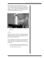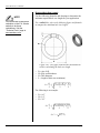
1
PowerDrill User’s Manual OBSOLETE EFFECTIVE JUNE 2013 E.H. Wachs 600 Knightsbridge Parkway Lincolnshire, IL 60069 www.ehwachs.com E.H. Wachs Part No. 76-MAN-00 Rev. OBS-0613, June 2013 Revision History: Original July 2008 Rev. 1 July 2011 Copyright © 2011 E.H. Wachs. All rights reserved. This manual may not be reproduced in whole or in part without the written consent of E.H. Wachs. PowerDrill User’s Manual Part No. 76-MAN-00, Rev. OBS-0613 E.H. Wachs Table of Contents Table of Contents Declaration of Conformity . . . . . . . . . . . . . . . . . . . . . . . . . . . . . . . . . . . . . . . . . . . . . . . . . . . . . . iv Chapter 1: About the PowerDrill . . . . . . . . . . . . . . . . . . . . . . . . . . . . . . . . . . . . . . . . . . . . . . . . 1 Purpose of This Manual . . . . . . . . . . . . . . . . . . . . . . . . . . . . . . . . . . . . . . . . . . . . . . . . . . . . . . . . . 1 How to Use The Manual . . . . . . . . . . . . . . . . . . . . . . . . . . . . . . . . . . . . . . . . . . . . . . . . . . . . . . . . 1 Symbols and Warnings . . . . . . . . . . . . . . . . . . . . . . . . . . . . . . . . . . . . . . . . . . . . . . . . . . . . . . . . . 2 Manual Updates and Revision Tracking . . . . . . . . . . . . . . . . . . . . . . . . . . . . . . . . . . . . . . . . . . . . 3 Equipment Description . . . . . . . . . . . . . . . . . . . . . . . . . . . . . . . . . . . . . . . . . . . . . . . . . . . . . . . . . 3 Machine Components . . . . . . . . . . . . . . . . . . . . . . . . . . . . . . . . . . . . . . . . . . . . . . . . . . . . . . . 4 Optional Configurations . . . . . . . . . . . . . . . . . . . . . . . . . . . . . . . . . . . . . . . . . . . . . . . . . . . . . . 5 Feed Reduction . . . . . . . . . . . . . . . . . . . . . . . . . . . . . . . . . . . . . . . . . . . . . . . . . . . . . . . . . 5 2-Speed Gearbox . . . . . . . . . . . . . . . . . . . . . . . . . . . . . . . . . . . . . . . . . . . . . . . . . . . . . . . . 5 Feed Reduction and 2-Speed Gearbox . . . . . . . . . . . . . . . . . . . . . . . . . . . . . . . . . . . . . . . . 5 Pivot Mount . . . . . . . . . . . . . . . . . . . . . . . . . . . . . . . . . . . . . . . . . . . . . . . . . . . . . . . . . . . . 5 Accessories and Hand Tools . . . . . . . . . . . . . . . . . . . . . . . . . . . . . . . . . . . . . . . . . . . . . . . . . . 6 Specifications . . . . . . . . . . . . . . . . . . . . . . . . . . . . . . . . . . . . . . . . . . . . . . . . . . . . . . . . . . . . . . 7 Drill Specifications . . . . . . . . . . . . . . . . . . . . . . . . . . . . . . . . . . . . . . . . . . . . . . . . . . . . . . 7 Spindle . . . . . . . . . . . . . . . . . . . . . . . . . . . . . . . . . . . . . . . . . . . . . . . . . . . . . . . . . . . . . . . . 8 Operating Envelope . . . . . . . . . . . . . . . . . . . . . . . . . . . . . . . . . . . . . . . . . . . . . . . . . . . . . . . . . 9 Chapter 2: Safety . . . . . . . . . . . . . . . . . . . . . . . . . . . . . . . . . . . . . . . . . . . . . . . . . . . . . . . . . . . . 17 Safe Operating Guidelines . . . . . . . . . . . . . . . . . . . . . . . . . . . . . . . . . . . . . . . . . . . . . . . . . . . . . . 17 Safe Operating Environment . . . . . . . . . . . . . . . . . . . . . . . . . . . . . . . . . . . . . . . . . . . . . . . . . 18 Operating and Maintenance Safety . . . . . . . . . . . . . . . . . . . . . . . . . . . . . . . . . . . . . . . . . . . . 18 Hydraulic Powered Equipment . . . . . . . . . . . . . . . . . . . . . . . . . . . . . . . . . . . . . . . . . . . . . . . . . . . 19 Pneumatic Powered Equipment . . . . . . . . . . . . . . . . . . . . . . . . . . . . . . . . . . . . . . . . . . . . . . . . . . 19 Loss or Shut-Off of Power Supply . . . . . . . . . . . . . . . . . . . . . . . . . . . . . . . . . . . . . . . . . . 19 Safety Alerts in This Manual . . . . . . . . . . . . . . . . . . . . . . . . . . . . . . . . . . . . . . . . . . . . . . . . . 19 Protective Equipment Requirements . . . . . . . . . . . . . . . . . . . . . . . . . . . . . . . . . . . . . . . . . . . 20 Protective Clothing . . . . . . . . . . . . . . . . . . . . . . . . . . . . . . . . . . . . . . . . . . . . . . . . . . . . . 20 Eye Protection . . . . . . . . . . . . . . . . . . . . . . . . . . . . . . . . . . . . . . . . . . . . . . . . . . . . . . . . . 20 Hearing Protection . . . . . . . . . . . . . . . . . . . . . . . . . . . . . . . . . . . . . . . . . . . . . . . . . . . . . . 21 Safe Operation of the PowerDrill . . . . . . . . . . . . . . . . . . . . . . . . . . . . . . . . . . . . . . . . . . . . . . . . 21 Intended Uses . . . . . . . . . . . . . . . . . . . . . . . . . . . . . . . . . . . . . . . . . . . . . . . . . . . . . . . . . . . . . 21 Proper Use of the PowerDrill . . . . . . . . . . . . . . . . . . . . . . . . . . . . . . . . . . . . . . . . . . . . . . . . . 21 Misuse . . . . . . . . . . . . . . . . . . . . . . . . . . . . . . . . . . . . . . . . . . . . . . . . . . . . . . . . . . . . . . . 22 PowerDrill Safety Features . . . . . . . . . . . . . . . . . . . . . . . . . . . . . . . . . . . . . . . . . . . . . . . . . . 24 Stop-on-Release Power Control . . . . . . . . . . . . . . . . . . . . . . . . . . . . . . . . . . . . . . . . . . . . 24 Over-Feed Safety Pin . . . . . . . . . . . . . . . . . . . . . . . . . . . . . . . . . . . . . . . . . . . . . . . . . . . . 24 Guidelines for Safe Setup, Operation, and Service . . . . . . . . . . . . . . . . . . . . . . . . . . . . . . . . 25 E.H. Wachs Company Part No. 76-MAN-00, Rev. OBS-0613 i PowerDrill User’s Manual Pre-Operation Checklist . . . . . . . . . . . . . . . . . . . . . . . . . . . . . . . . . . . . . . . . . . . . . . . . . Operating Safety . . . . . . . . . . . . . . . . . . . . . . . . . . . . . . . . . . . . . . . . . . . . . . . . . . . . . . . Operator Position . . . . . . . . . . . . . . . . . . . . . . . . . . . . . . . . . . . . . . . . . . . . . . . . . . . . . . . Service Checklist . . . . . . . . . . . . . . . . . . . . . . . . . . . . . . . . . . . . . . . . . . . . . . . . . . . . . . . Loss of Power Procedure . . . . . . . . . . . . . . . . . . . . . . . . . . . . . . . . . . . . . . . . . . . . . . . . . Disconnecting Power . . . . . . . . . . . . . . . . . . . . . . . . . . . . . . . . . . . . . . . . . . . . . . . . . . . . Safe Lifting and Handling . . . . . . . . . . . . . . . . . . . . . . . . . . . . . . . . . . . . . . . . . . . . . . . . . . . Safety Labels . . . . . . . . . . . . . . . . . . . . . . . . . . . . . . . . . . . . . . . . . . . . . . . . . . . . . . . . . . . . . . . . Machine Safety . . . . . . . . . . . . . . . . . . . . . . . . . . . . . . . . . . . . . . . . . . . . . . . . . . . . . . . . . . . . . . 25 26 26 26 26 27 28 29 32 Chapter 3: Operating Instructions . . . . . . . . . . . . . . . . . . . . . . . . . . . . . . . . . . . . . . . . . . . . . Installing the Drill . . . . . . . . . . . . . . . . . . . . . . . . . . . . . . . . . . . . . . . . . . . . . . . . . . . . . . . . . . . . Configuring and Mounting the Saddle . . . . . . . . . . . . . . . . . . . . . . . . . . . . . . . . . . . . . . . . . Using the Magnetic Protractor . . . . . . . . . . . . . . . . . . . . . . . . . . . . . . . . . . . . . . . . . . . . . Mounting the Drill . . . . . . . . . . . . . . . . . . . . . . . . . . . . . . . . . . . . . . . . . . . . . . . . . . . . . . . . . Position Adjustments . . . . . . . . . . . . . . . . . . . . . . . . . . . . . . . . . . . . . . . . . . . . . . . . . . . . . . . . . . Rotating the Saddle Around the Pipe . . . . . . . . . . . . . . . . . . . . . . . . . . . . . . . . . . . . . . . . . . Moving the Column on the Saddle . . . . . . . . . . . . . . . . . . . . . . . . . . . . . . . . . . . . . . . . . . . . Moving the Drill on the Column . . . . . . . . . . . . . . . . . . . . . . . . . . . . . . . . . . . . . . . . . . . . . . Rotating the Drill on the Column . . . . . . . . . . . . . . . . . . . . . . . . . . . . . . . . . . . . . . . . . . . . . Pivoting the Drill . . . . . . . . . . . . . . . . . . . . . . . . . . . . . . . . . . . . . . . . . . . . . . . . . . . . . . . . . . Using the Laser Center . . . . . . . . . . . . . . . . . . . . . . . . . . . . . . . . . . . . . . . . . . . . . . . . . . . . . Operating the Drill . . . . . . . . . . . . . . . . . . . . . . . . . . . . . . . . . . . . . . . . . . . . . . . . . . . . . . . . . . . . Using the Two-Speed Gearbox . . . . . . . . . . . . . . . . . . . . . . . . . . . . . . . . . . . . . . . . . . . . . . . Adjusting the Feed Tension . . . . . . . . . . . . . . . . . . . . . . . . . . . . . . . . . . . . . . . . . . . . . . . . . . Drilling . . . . . . . . . . . . . . . . . . . . . . . . . . . . . . . . . . . . . . . . . . . . . . . . . . . . . . . . . . . . . . . . . . Spot Facing . . . . . . . . . . . . . . . . . . . . . . . . . . . . . . . . . . . . . . . . . . . . . . . . . . . . . . . . . . . . . . Tapping . . . . . . . . . . . . . . . . . . . . . . . . . . . . . . . . . . . . . . . . . . . . . . . . . . . . . . . . . . . . . . . . . Cutting with a Hole Saw . . . . . . . . . . . . . . . . . . . . . . . . . . . . . . . . . . . . . . . . . . . . . . . . . . . . 33 33 34 38 41 44 44 45 46 47 47 48 49 49 50 51 56 60 65 Chapter 4: Maintenance . . . . . . . . . . . . . . . . . . . . . . . . . . . . . . . . . . . . . . . . . . . . . . . . . . . . . . Lubrication . . . . . . . . . . . . . . . . . . . . . . . . . . . . . . . . . . . . . . . . . . . . . . . . . . . . . . . . . . . . . . . . . . Grease Fittings . . . . . . . . . . . . . . . . . . . . . . . . . . . . . . . . . . . . . . . . . . . . . . . . . . . . . . . . . . . . Column . . . . . . . . . . . . . . . . . . . . . . . . . . . . . . . . . . . . . . . . . . . . . . . . . . . . . . . . . . . . . . . . . Repositioning the Feed Handle . . . . . . . . . . . . . . . . . . . . . . . . . . . . . . . . . . . . . . . . . . . . . . . . . . Air Motor Maintenance . . . . . . . . . . . . . . . . . . . . . . . . . . . . . . . . . . . . . . . . . . . . . . . . . . . . . . . . Disassembling Air Motor Subassemblies . . . . . . . . . . . . . . . . . . . . . . . . . . . . . . . . . . . . . . . Right Angle Head . . . . . . . . . . . . . . . . . . . . . . . . . . . . . . . . . . . . . . . . . . . . . . . . . . . . . . Gear Case . . . . . . . . . . . . . . . . . . . . . . . . . . . . . . . . . . . . . . . . . . . . . . . . . . . . . . . . . . . . . Motor . . . . . . . . . . . . . . . . . . . . . . . . . . . . . . . . . . . . . . . . . . . . . . . . . . . . . . . . . . . . . . . . Handle . . . . . . . . . . . . . . . . . . . . . . . . . . . . . . . . . . . . . . . . . . . . . . . . . . . . . . . . . . . . . . . Reassembly . . . . . . . . . . . . . . . . . . . . . . . . . . . . . . . . . . . . . . . . . . . . . . . . . . . . . . . . . . . . . . Motor . . . . . . . . . . . . . . . . . . . . . . . . . . . . . . . . . . . . . . . . . . . . . . . . . . . . . . . . . . . . . . . . Air Motor Vanes . . . . . . . . . . . . . . . . . . . . . . . . . . . . . . . . . . . . . . . . . . . . . . . . . . . . . . . Right Angle Head . . . . . . . . . . . . . . . . . . . . . . . . . . . . . . . . . . . . . . . . . . . . . . . . . . . . . . 73 73 73 75 75 85 86 86 86 86 86 86 87 87 88 ii Part No. 76-MAN-00, Rev. OBS-0613 E.H. Wachs Company Table of Contents Chapter 5: Parts List and Ordering Information . . . . . . . . . . . . . . . . . . . . . . . . . . . . . . . . . . 89 Ordering Information . . . . . . . . . . . . . . . . . . . . . . . . . . . . . . . . . . . . . . . . . . . . . . . . . . . . . . . . . . 89 Ordering Replacement Parts . . . . . . . . . . . . . . . . . . . . . . . . . . . . . . . . . . . . . . . . . . . . . . . . . 89 Repair Information . . . . . . . . . . . . . . . . . . . . . . . . . . . . . . . . . . . . . . . . . . . . . . . . . . . . . . . . . 89 Warranty Information . . . . . . . . . . . . . . . . . . . . . . . . . . . . . . . . . . . . . . . . . . . . . . . . . . . . . . 90 Return Goods Address . . . . . . . . . . . . . . . . . . . . . . . . . . . . . . . . . . . . . . . . . . . . . . . . . . . . . . 90 Drawings and Parts Lists . . . . . . . . . . . . . . . . . . . . . . . . . . . . . . . . . . . . . . . . . . . . . . . . . . . . . . . 90 E.H. Wachs Company Part No. 76-MAN-00, Rev. OBS-0613 iii PowerDrill User’s Manual iv Part No. 76-MAN-00, Rev. OBS-0613 E.H. Wachs Company Chapter 1, About the PowerDrill Chapter 1 About the PowerDrill PURPOSE OF THIS MANUAL This manual explains how to operate and maintain the multi-axis PowerDrill. It includes instructions for set-up, operation, and maintenance. It also contains parts lists, diagrams, and service information to help you order replacement parts and perform user-serviceable repairs. Before operating the PowerDrill, you should read through this manual and become familiar with all instructions. In This Chapter PURPOSE OF THIS MANUAL HOW TO USE THE MANUAL SYMBOLS AND WARNINGS MANUAL UPDATES AND REVISION TRACKING EQUIPMENT DESCRIPTION HOW TO USE THE MANUAL This manual is organized to help you quickly find the information you need. Each chapter describes a specific topic on using or maintaining your equipment. Throughout this manual, refer to this column for warnings, cautions, and notices with supplementary information. Each page is designed with two columns. This large column on the inside of the page contains instructions and illustrations. Use these instructions to operate and maintain the equipment. The narrower column on the outside contains additional information such as warnings, special notes, and definitions. Refer to it for safety notes and other information. E.H. Wachs Company Part No. 76-MAN-00, Rev. OBS-0613 1 PowerDrill User’s Manual SYMBOLS AND WARNINGS The following symbols are used throughout this manual to indicate special notes and warnings. They appear in the outside column of the page, next to the section they refer to. Make sure you understand what each symbol means, and follow all instructions for cautions and warnings. WARNING A WARNING alert with the safety alert symbol indicates a potentially hazardous situation that could result in serious injury or death. This is the safety alert symbol. It is used to alert you to potential personal injury hazards. Obey all safety messages that follow this symbol to avoid possible injury or death. CAUTION A CAUTION alert with the safety alert symbol indicates a potentially hazardous situation that could result in minor or moderate injury. CAUTION A CAUTION alert with the damage alert symbol indicates a situation that will result in damage to the equipment. This is the equipment damage alert symbol. It is used to alert you to potential equipment damage situations. Obey all messages that follow this symbol to avoid damaging the equipment or workpiece on which it is operating. IMPORTANT An IMPORTANT alert with the damage alert symbol indicates a situation that may result in damage to the equipment. 2 Part No. 76-MAN-00, Rev. OBS-0613 E.H. Wachs Company Chapter 1, About the PowerDrill: Manual Updates and Revision Tracking NOTE NOTE This symbol indicates a user note. Notes provide additional information to supplement the instructions, or tips for easier operation. A NOTE provides supplementary information or operating tips. MANUAL UPDATES AND REVISION TRACKING Occasionally, we will update manuals with improved operation or maintenance procedures, or with corrections if necessary. When a manual is revised, we will update the revision history on the title page. You may have factory service or upgrades performed on the equipment. If this service changes any technical data or operation and maintenance procedures, we will include a revised manual when we return the equipment to you. Current versions of E.H. Wachs Company manuals are also available in PDF format. You can request an electronic copy of this manual by emailing customer service at [email protected]. EQUIPMENT DESCRIPTION The multi-axis PowerDrill is designed for drilling, boring, and tapping pipes 6” or more in diameter. The standard mounting saddle (part no. 76-400-00) is designed for pipes from 6” to 24” diameter. Saddles for other pipe sizes, or for plate or other structural shapes, can be custom-ordered. The drill features a long feed travel for flexibility in setup and tool installation. Options include a two-speed gearbox and multiple axes of adjustment that allow variable drilling configurations. A modular design and simple chain mount make setup easy, even for one operator. Single-direction and reversible air motors are standard, and hydraulic or electric motors are available. (A reversible motor is required for tapping applications.) The PowerDrill can use any standard motor supplied for Wachs’ popular low clearance split frame (LCSF) product line. E.H. Wachs Company Part No. 76-MAN-00, Rev. OBS-0613 NOTE An air treatment module, or ATM (not supplied), is required for the air drive. You can provide your own ATM or order one from E.H. Wachs (part no. 26-407-00). 3 PowerDrill User’s Manual Machine Components The PowerDrill consists of the following modular assemblies: • • • • • • Saddle and clamping chain (30 lb; 13.6 kg) Mounting column assembly (69 lb; 31.3 kg) Spindle assembly (10-20 lb; 4.5-9.0 kg) Swivel for pivot option (10 lb; 4.5 kg) Drive motor, air (14 lb; 6.4 kg) Drive motor, hydraulic (26 lb; 11.8 kg). Air motor Gearbox Feed handle Speed select lever (center position is neutral) Spindle Feed rails Column Mounting flange Saddle Mounting chain Figure 1-1. The photo shows the major components of the PowerDrill. 4 Part No. 76-MAN-00, Rev. OBS-0613 E.H. Wachs Company Chapter 1, About the PowerDrill: Equipment Description Optional Configurations The base PowerDrill (part no. 76-000-01) features a hightorque gearbox and standard feed system. Chapter 5 includes a configuration drawing for the base drill. The following optional configurations are available. Feed Reduction A 4:1 feed gear reduction is available. This option makes feeding the drill easier, reducing operator fatigue. A drawing of this configuration (part no. 76-000-02) is included in Chapter 5. 2-Speed Gearbox The 2-speed gearbox includes the standard high-torque gearing (3:1 motor speed reduction) and a higher speed setting (1:1 motor speed). The higher speed is useful for drilling smaller holes using a twist drill insert. Low speed should be used for tapping and cutting with hole saws. IMPORTANT The feed reduction results in much greater downward force than you feel on the feed handle. Take care when applying feed pressure not to overload the tooling. A drawing of this configuration (part no. 76-000-03) is included in Chapter 5. Feed Reduction and 2-Speed Gearbox A configuration with both feed reduction and 2-speed gearbox is available. A drawing of this configuration (part no. 76-000-04) is included in Chapter 5. Pivot Mount A 360° pivoting mount assembly (part no. 76-402-00) is available with any drill configuration. The pivot feature allows the drill to be rotated for drilling non-radial holes, or for positioning the drill when mounting straight over the desired drilling location is not possible. The pivot mount accessory includes a base plate that is installed between the saddle and column mounting flange. The base plate provides 4.75” (121 mm) of linear adjustment that allows you to drill radial holes that are not tangent to the saddle. Two gib plates are provided to secure the base plate to the saddle. E.H. Wachs Company Part No. 76-MAN-00, Rev. OBS-0613 5 PowerDrill User’s Manual Column mounting flange Base plate Gib plates Base plate adjustment Figure 1-2. The base plate is held in place on the saddle with two gib plates. Loosen the gibs to move the drill column perpendicular to the axis of the pipe. Accessories and Hand Tools The PowerDrill is provided with the following standard accessories and hand tools. 76-134-00 #3 MT spindle adapter 76-158-00 0.18-0.81” (4.5-20.6 mm) chuck assembly 76-166-00 #3/#4 MT eject drift 60-227-00 Tool box 90-800-01 1-1/4” open end wrench 90-800-26 7/8” combination wrench 90-800-40 3/16-3/8” hex wrench set 90-800-45 3/8” drive ratchet 90-800-46 3/8” hex driver long socket 90-800-74 5/16” hex driver short socket 90-800-81 7/8” socket, 3/8” drive The following are optional accessories available for the PowerDrill. 76-133-00 6 R8 Collet Spindle Adapter Part No. 76-MAN-00, Rev. OBS-0613 E.H. Wachs Company Chapter 1, About the PowerDrill: Equipment Description 76-169-00 Laser Center 76-171-00 #4 MT Spindle Adapter 76-172-00 Mag base protractor 76-173-00 ¾” End Mill Holder x #3 MT Contact the E.H. Wachs Company for availability of other accessories and tooling, or to request a quote on custom tooling. See “Ordering Information” in Chapter 5. Specifications Drill Specifications • • • • • • Feed travel: 11-1/4” (286 mm) See “A” in Figure 1-3 below. Drill vertical adjustment on column: 8-1/2" (216 mm) See “B” in Figure 1-3 below. Drill head angular adjustment about column: 360° See “C” in Figure 1-3 below. Drill head vertical position on column and angular position on column are independently adjustable. Drill head angular adjustment from vertical: 360° See “D” in Figure 1-3 below. Drill head angular position from vertical is infinitely variable with the pivoting option part number 76-402-00. Drill linear adjustment on pipe saddle: 9" (229 mm) Max. pipe diameter for standard saddle: 24" (610 mm) Other mounting configurations available. E.H. Wachs Company Part No. 76-MAN-00, Rev. OBS-0613 7 PowerDrill User’s Manual D B C A Figure 1-3. The photo illustrates the feed travel (A), vertical adjustment (B), angular adjustment (C), and pivot angle adjustment (D). Spindle Base drill speed 1/3 of drive motor RPM 2-speed gearbox high speed Same RPM as drive motor 8 Spindle bore 1.5” (38 mm) straight bore Adapter sockets accepted Up to #4 MT Maximum hole size 5-1/4” (133 mm) hole saw Power tap Up to 1-5/8"-8 UN Step drill sizes Up to 2-1/2" in 1/2" increments Part No. 76-MAN-00, Rev. OBS-0613 E.H. Wachs Company Chapter 1, About the PowerDrill: Equipment Description Dimensions Height Drill: 15.1”-35.4” (384-899 mm) Saddle: 3.2” (81 mm) Air motor: 3.2” (81 mm) Width Standard: 14.2” (361 mm) With feed reduction: 16.3” (414 mm) Length (front to back) Min. without pivot: 12.1” (306 mm) Max. without pivot: 20.8” (528 mm) Min. with pivot: 16.4” (415 mm) Max. with pivot: 23.3” (592 mm) Weight (total) 76-000-01: 136 lb (62 kg) 76-000-02: 139 lb (64 kg) 76-000-03: 146 lb (67 kg) 76-000-04: 149 lb (68 kg) Pivot option: 22 lb (10 kg) (including adjustable base plate) Air motor: 14 lb (6.4 kg) Operating Envelope The drawings on the following pages illustrate the component sizes and operating clearances for each of the PowerDrill configurations. Operating envelopes for the standard and reversible air motors are included. E.H. Wachs Company Part No. 76-MAN-00, Rev. OBS-0613 9 PowerDrill User’s Manual 10 Part No. 76-MAN-00, Rev. OBS-0613 E.H. Wachs Company Chapter 1, About the PowerDrill: Equipment Description E.H. Wachs Company Part No. 76-MAN-00, Rev. OBS-0613 11 PowerDrill User’s Manual 12 Part No. 76-MAN-00, Rev. OBS-0613 E.H. Wachs Company Chapter 1, About the PowerDrill: Equipment Description E.H. Wachs Company Part No. 76-MAN-00, Rev. OBS-0613 13 PowerDrill User’s Manual 14 Part No. 76-MAN-00, Rev. OBS-0613 E.H. Wachs Company Chapter 1, About the PowerDrill: Equipment Description E.H. Wachs Company Part No. 76-MAN-00, Rev. OBS-0613 15 PowerDrill User’s Manual 16 Part No. 76-MAN-00, Rev. OBS-0613 E.H. Wachs Company Chapter 2, Safety Chapter 2 Safety In This Chapter E.H. Wachs takes great pride in designing and manufacturing safe, high-quality products. We make user safety a top priority in the design of all our products. Read this chapter carefully before operating your E.H. Wachs equipment. It contains important safety instructions and recommendations. SAFE OPERATING GUIDELINES SAFETY LABELS MACHINE SAFETY SAFE OPERATING GUIDELINES Follow these guidelines for safe operation of all E.H. Wachs equipment. • • • READ THE OPERATING MANUAL. Make sure you understand all setup and operating instructions before you begin. Keep this manual with the machine. INSPECT MACHINE AND ACCESSORIES BEFORE USE. Before starting the machine, look for loose bolts or nuts, leaking lubricant, rusted components, and any other physical conditions that may affect operation. Properly maintaining the machine can greatly decrease the chances for injury. ALWAYS READ STICKERS AND LABELS. Make sure all labels and stickers are in place, clearly legible, and in good condition. Refer to “Safety Labels” later in this chapter for label locations on the machine. Replace any damaged or missing safety labels; see Chapter 10 for ordering information. E.H. Wachs Company Part No. 76-MAN-00, Rev. OBS-0613 Look for this symbol throughout the manual. It indicates a personal injury hazard. 17 PowerDrill User’s Manual • KEEP CLEAR OF MOVING PARTS. Keep hands, arms, and • fingers clear of all rotating or moving parts. Always turn the machine off and disconnect the power source before doing any adjustments or service. SECURE LOOSE CLOTHING AND JEWELRY. Secure or remove loose-fitting clothing and jewelry, and securely bind long hair, to prevent them from getting caught in moving parts of the machine. • FOLLOW SAFE PROCEDURES FOR HANDLING LUBRICANTS. Refer to the manufacturer’s instructions and the Material Safety Data Sheets. Safe Operating Environment • • • Do not use this equipment in a potentially explosive atmosphere. Fire or explosion could result, with the risk of serious injury or death. Provide adequate lighting to use the equipment, in accordance with worksite or local regulations. KEEP WORK AREA CLEAR. Keep all clutter and nonessential materials out of the work area. Only people directly involved with the work being performed should have access to the area. Operating and Maintenance Safety • • • • • • 18 This equipment is to be operated and maintained only by qualified, trained personnel. Make sure the equipment is stable when attached to the workpiece for the operation. Ensuring stability of the installed tool is the responsibility of the operator. Make sure the workpiece is supported adequately for installation of the equipment. This includes supporting any workpiece “fall-off” section when severing the workpiece. Ensuring support of the workpiece is the responsibility of the operator. Tooling on any cutting equipment—including lathe tools, saw blades, milling tools, etc.—may get very hot. Do not touch tooling until you have made sure it is cool enough to handle. Wear gloves when removing or cleaning up chips and cutting debris. Chips can be very sharp and cause cuts. Before performing any service on the equipment, disconnect the power source. Follow all lock-out/tag-out procedures required at the worksite. Part No. 76-MAN-00, Rev. OBS-0613 E.H. Wachs Company Chapter 2, Safety: Safe Operating Guidelines Hydraulic Powered Equipment • • Hydraulic components such as hoses, motors, and manifolds will get hot during operation and may cause burns. Do not touch hydraulic components, except for operator controls, during or after operating the machine. Hydraulic injection injury—A pinhole in a hydraulic hose or fitting can eject fluid with enough force to pierce skin. Check hoses and fittings regularly for leaks. Do not use bare hands to check for leaks while the system is pressurized. If you suspect a leak, move a piece of paper or cardboard at least 6 inches (15 cm) over the suspicious area and watch for fluid spraying on the surface. Pneumatic Powered Equipment • • WARNING Injection of hydraulic fluid through the skin is a serious injury that can result in infection, tissue damage, and possible loss of limb. Seek medical treatment immediately. First aid is not sufficient treatment for injection injury. Air motors may get hot during operation and may cause burns. Do not touch the air motor, except for operator controls, during or after operating the machine. Before disconnecting the air line from the equipment, always turn off air at the source and bleed all residual air pressure at the air motor. Loss or Shut-Off of Power Supply Also refer to the section “Loss of Power Procedure” on page 26 for specific instructions. • • • If the power source to the equipment is lost, disconnect power from the equipment and lock out the power supply immediately to prevent accidental restarting of the machine. ELECTRIC POWERED EQUIPMENT—If the electric drive shuts off because of its built-in thermal protection, disconnect the motor from the power source immediately. For all power sources, follow all lock-out/tag-out procedures required at the worksite when disconnecting or servicing the equipment. Safety Alerts in This Manual The following alerts are used throughout this manual to indicate operator safety hazards. In all cases, these alerts include a notice describing the hazard and the means to avoid or reduce risk. Carefully read all safety alerts. E.H. Wachs Company Part No. 76-MAN-00, Rev. OBS-0613 19 PowerDrill User’s Manual This icon is displayed with any safety alert that indicates a personal injury hazard. WARNING This safety alert, with the personal injury hazard symbol, indicates a potentially hazardous situation that, if not avoided, could result in death or serious injury. CAUTION This safety alert, with the personal injury hazard symbol, indicates a potentially hazardous situation that, if not avoided, could result in minor or moderate injury. Protective Equipment Requirements Protective Clothing Wear safety shoes when operating or servicing the equipment. Serious injury could result from dropping the machine or its components. NOTE Gloves should be worn when cleaning up chips and other cutting debris. Chips can be very sharp and can cause serious cuts. Do not wear gloves when the machine is operating. Do not wear gloves while operating the machine. Gloves can become entangled in moving parts, resulting in serious injury. Gloves may be worn when setting up the machine or cleaning up after the operation, but take them off when operating the machine. Eye Protection Always wear impact-resistant eye protection while operating or working near this equipment. For additional information on eye and face protection, refer to Federal OSHA regulations, 29 Code of Federal Regulations, Section 1910.133., Eye and Face Protection and 20 Part No. 76-MAN-00, Rev. OBS-0613 E.H. Wachs Company Chapter 2, Safety: Safe Operation of the PowerDrill American National Standards Institute, ANSI Z87.1, Occupational and Educational Eye and Face Protection. Hearing Protection This equipment can produce noise levels above 80 dB. Hearing protection is required when operating the equipment. The operation of other tools and equipment in the area, reflective surfaces, process noises, and resonant structures can increase the noise level in the area. For additional information on hearing protection, refer to Federal OSHA regulations, 29 Code of Federal Regulations, Section 1910.95, Occupational Noise Exposure and ANSI S12.6 Hearing Protectors. SAFE OPERATION OF THE POWERDRILL Intended Uses The PowerDrill is designed to O.D. mount on pipes (or other objects with custom mounting adapters), and perform drilling, hole-cutting, spot facing, and tapping operations.A variety of accessories and tooling is available for different cutting applications. Make sure to follow all safety guidelines and procedures required for machining operations at the work site, including personal protective equipment (PPE). Do not use the PowerDrill in a manner that violates these guidelines. Proper Use of the PowerDrill • • • The PowerDrill should only be used by trained, qualified operators. The workpiece must be within the operating capacity of the PowerDrill. See operating envelope information and drawings in Chapter 1. Make sure the operating environment allows you to mount the machine securely and squarely on the workpiece. E.H. Wachs Company Part No. 76-MAN-00, Rev. OBS-0613 21 PowerDrill User’s Manual • • • Make sure there is adequate clearance around the PowerDrill and workpiece to operate the machine controls as described in the operating instructions (Chapter 3). Mount the PowerDrill with the drive adapter positioned for convenient mounting and operation of the drive motor. Use the PowerDrill only on empty, depressurized pipe. Misuse • • • 22 Do not attempt to mount or operate the PowerDrill on any workpiece to which it cannot be securely mounted. Do not attempt to mount or operate the PowerDrill on any workpiece that is not stable enough to hold the machine. Do not disable any safety feature of the PowerDrill or remove any safety labeling. Replace worn or damaged safety labels immediately. (See “Safety Labels” later in this chapter.) Part No. 76-MAN-00, Rev. OBS-0613 E.H. Wachs Company Chapter 2, Safety: Safe Operation of the PowerDrill Potential Hazards The following figures illustrate potential hazards of operating the PowerDrill. Refer to the description of each hazard for guidelines on safe operation. 2 3 1 Figure 2-1. Potential operating hazards of the PowerDrill. See the descriptions in the side column. 4 1. Drop/crush hazard—The drill can fall or shift when you are mounting it or adjusting the height or pivot angle. Support the drill with a lifting device attached to the lift eyes while mounting or making adjustments. 2. Hot surfaces—Air motors and hydraulic components such as hoses, manifolds, and motors can become very hot during operation. Make sure these components are not hot before touching them. 3. Entanglement hazard for gloves or clothing—Do not wear gloves or loose-fitting clothing when operating the PowerDrill. They can become entangled with moving parts, resulting in serious injury. 4. Sharp cutting tools—Cutting tools used with the PowerDrill can be very sharp. Be careful when handling the tools, and stay clear of them when the drill is operating. 5. Chips—The metal debris from the cutting process can be very sharp and very hot. Use care in cleaning debris from the machine and cleaning up the work area. Stop the machine before clearing chips. Use appropriate gloves when handling chips. 5 Figure 2-2. Potential operating hazards of the PowerDrill. See the descriptions in the side column. E.H. Wachs Company Part No. 76-MAN-00, Rev. OBS-0613 23 PowerDrill User’s Manual PowerDrill Safety Features The design of the PowerDrill incorporates the following features for safe operation. Stop-on-Release Power Control WARNING Do not disable or override the stop-on-release feature. Letting the machine run when you are not holding the power control could result in serious injury. All drives for the PowerDrill (pneumatic and hydraulic) require the operator to hold the power control on to operate the machine. When the operator releases the power control, the PowerDrill stops immediately. Figure 2-3. Hold the air motor trigger to operate the PowerDrill (left). When you release the trigger (right), the air motor shuts off. Figure 2-4. Hold the hydraulic lever to operate the PowerDrill (left). When you release the lever (right), the hydraulic motor shuts off. Over-Feed Safety Pin The pin is inserted through the support column to prevent the drill from being raised past the top of the column. Always have the pin in place when operating the drill. 24 Part No. 76-MAN-00, Rev. OBS-0613 E.H. Wachs Company Chapter 2, Safety: Safe Operation of the PowerDrill Figure 2-5. Insert the over-feed pin through the top of the support column before operating the drill. Guidelines for Safe Setup, Operation, and Service CAUTION: When adjusting the position of the PowerDrill, support the machine using a lifting device attached to the lift eyes. When adjustment bolts are loosened, the drill could slip or drop suddenly. Injuries could result if the machine slips during position adjustment. The PowerDrill is designed to be disassembled into modules for convenient storage and installation. Even when disassembled, some of the modules are too heavy for one person to lift (more than 40 lb/18 kg). Use a lifting device to install the PowerDrill, and to lift the machine into and out of its case. Pre-Operation Checklist Every time you use the PowerDrill, perform the following checks to make sure it is in good operating condition: • • • • Check that all safety components are operating properly. Inspect it for damage or wear that could affect operation and safe use of the machine. Repair any defective component before using the machine. Make sure the machine is clean and properly lubricated. Make sure that tooling is sharp and in good condition. Poor quality tooling can cause difficult cutting and the possibility of machine malfunction and/or injury. E.H. Wachs Company Part No. 76-MAN-00, Rev. OBS-0613 25 PowerDrill User’s Manual • Check power connections (pneumatic or hydraulic) to make sure they are in good condition. Operating Safety • • Stop the PowerDrill drive motion to clear chips or make any machine adjustments. Keep air and hydraulic hoses and electrical cords away from moving parts while operating the machine. Operator Position It is recommended that you operate the PowerDrill with the drive motor on the same side as the feed handle. This lets you avoid reaching across the work area while operating the machine. The drive motor has multiple mounting holes in the flange, allowing you to mount it in different positions. You can mount the feed handle on either side of the PowerDrill; see the instructions in Chapter 4. If the feed handle location is not convenient for the work environment, move it to the other side. Service Checklist • • Disconnect power from the PowerDrill during service. See instructions in the following section. Remove the drive motor and tooling unless they are part of the service procedure. Loss of Power Procedure If air or hydraulic power to the PowerDrill is lost or interrupted during operation, perform the following procedure before restarting the machine: 26 1. Release the power lever on the drive motor (air or hydraulic). 2. Put the speed select lever in the neutral (center) position (for machines with the two-speed gearbox). 3. Turn off the power supply at the source. 4. Bleed any residual pressure from the air or hydraulic hoses. Part No. 76-MAN-00, Rev. OBS-0613 E.H. Wachs Company Chapter 2, Safety: Safe Operation of the PowerDrill 5. Use the feed handle on the PowerDrill to move the cutting tool away from contact with the workpiece. Make sure the tooling is not damaged. Disconnecting Power The following photos show the means of disconnecting power for the PowerDrill. Follow all lock-out/tag-out procedures at your work site. • PNEUMATIC POWER—To disconnect power from the pneumatic PowerDrill, remove the air line from the air motor coupling. WARNING Before disconnecting the air line, always turn off air at the source and bleed all residual air pressure at the air motor. Disconnecting the air line while under pressure could result in serious injury. Figure 2-6. Disconnect pneumatic power by removing the air line from the pneumatic drive. • HYDRAULIC POWER—To disconnect power from the hydraulic PowerDrill, remove the hydraulic hoses from the fittings on the manifold. WARNING Hydraulic components such as hoses, motors, and manifolds will get hot during operation and may cause burns. Use appropriate gloves or wait until the components cool before touching them. E.H. Wachs Company Part No. 76-MAN-00, Rev. OBS-0613 27 PowerDrill User’s Manual Figure 2-7. Disconnect hydraulic power by removing the hydraulic hoses from the fittings on the manifold. Safe Lifting and Handling • • • • Machines or assemblies over 40 lb (18 kg) must be lifted by two people or a lifting device. See the machine weight table below. It is the responsibility of the end user to determine whether a machine or assembly can be lifted by two or more people. A lifting device is recommended for machines or assemblies that cannot be handled easily by two people. The PowerDrill is equipped with eye bolts in the top of the feed assembly. Attach a lifting device to these eye bolts to handle the machine. Do not rig or lift the PowerDrill while power is attached. Whenever possible, remove the drive motor and tooling while lifting and handling the machine. It is not recommended to lift the PowerDrill with the saddle attached. Table 1: PowerDrill Subassembly Weights Subassembly 28 Part No.* Weight Saddle assembly 76-400-00 30 lb (13.6 kg) Column assembly 76-401-00, 76-403-00, 76-404-00, 76-405-00, 76-406-00 69 lb (31.3 kg) Part No. 76-MAN-00, Rev. OBS-0613 E.H. Wachs Company Chapter 2, Safety: Safety Labels Table 1: PowerDrill Subassembly Weights Subassembly Part No.* Weight Spindle assembly (single speed) 76-407-00, 76-408-00 10 lb (4.5 kg) Spindle assembly (two speed) 76-407-00, 76-409-00 20 lb (9.0 kg) Swivel (pivot option) 76-401-00 10 lb (4.5 kg) Drive motor—air 60-4010-01 14 lb (6.4 kg) Drive motor—hydraulic 76-411-00 26 lb (11.8 kg) * Multiple numbers indicate all machine assemblies that are part of the subassembly. SAFETY LABELS The following safety labels are on the PowerDrill. Figure 2-8. This label is on the axial column clamp on the back of the drill. Make sure to support the drill on the column when loosening the height adjustment bolts. The drill could slide down the column, causing personal injury or equipment damage. E.H. Wachs Company Part No. 76-MAN-00, Rev. OBS-0613 29 PowerDrill User’s Manual Figure 2-9. This label is on the feed lock clamp. Hold the feed lever when you loosen the feed lock lever. The spindle assembly could fall when loosening the lock, causing personal injury or equipment damage. Figure 2-10. The crush injury label is on both sides of the PowerDrill. Support the machine with a lifting device when making any adjustments. Figure 2-11. The crush and force from above label is on both sides of the PowerDrill. Support the machine with a lifting device when making any adjustments. Figure 2-12. The rotating blade hazard label is on the front of the PowerDrill. Keep hands away from the bit or blade while the machine is running or while power is energized. 30 Part No. 76-MAN-00, Rev. OBS-0613 E.H. Wachs Company Chapter 2, Safety: Safety Labels Figure 2-13. The lifting point label is on the frame in 2 places next to the lifting eyes. Always lift the machine using the lifting eyes. Do not lift on any other component. Figure 2-14. The two-person lift label is on both sides of the machine. Do not lift the machine by yourself. (Use of a lifting device is recommended.) Figure 2-15. The laser exposure label is on the optional laser center. Avoid eye exposure with the laser. E.H. Wachs Company Part No. 76-MAN-00, Rev. OBS-0613 31 PowerDrill User’s Manual MACHINE SAFETY To avoid damaging the equipment, follow these usage guidelines. • • • • • • 32 Lubricate the machinery according to the recommendations in Chapter 4. Before starting the machine, make sure the tool holder and tooling are secure. When using a lifting device to pick up or position the drill, always use the attached lifting eyes (part no. 90099-92). Do not attach a lifting device to any other component. (For drills with the optional feed reduction.) Do not overfeed the drill while drilling. The PowerDrill uses a feed reduction handle, so turning the handle produces a greater feed thrust than a conventional drill press. (For drills with the optional two-speed gearbox.) Do not operate the drill at the high speed setting when cutting large holes with a hole saw. Larger tools require the greater torque available at the low speed setting. (For drills with the optional two-speed gearbox.) Do not move the speed select lever when the drill is running. This could damage the gearbox. Part No. 76-MAN-00, Rev. OBS-0613 E.H. Wachs Company Chapter 3, Operating Instructions Chapter 3 Operating Instructions In This Chapter INSTALLING THE DRILL INSTALLING THE DRILL POSITION ADJUSTMENTS The drill can be installed module by module on the pipe to make installation easier. The drill components are light enough to be mounted by one person, but you may find it easier to perform the installation with two people. OPERATING THE DRILL Figure 3-1 shows the drill components stored in the case. Mounting column and feed slide assembly Gearbox assembly Air motor Saddle and chain Figure 3-1. The photo shows the disassembled drill in its storage case. See Table 1 in Chapter 2 for weights of the subassemblies. E.H. Wachs Company Part No. 76-MAN-00, Rev. OBS-0613 33 PowerDrill User’s Manual Configuring and Mounting the Saddle 1. Take the saddle out of the case. If necessary, remove the mounting shoes and adjust them for the pipe size you are drilling. Figure 3-2. Attach the mounting shoes to the saddle using the supplied screws. NOTE You can set the mounting shoes in different locations on the saddle if the application requires off-center mounting. 34 There are three mounting locations on the saddle for the mounting shoes. Set all four shoes to the same location on the saddle. Table 1: Saddle Mounting Shoe Locations Pipe Diameter Mounting Position Figure Reference 6”-14” (150-356 mm) Inner Figure 3-3 14”-22” (356-558 mm) Middle Figure 3-4 22”-24” (558-610 mm) Outer Figure 3-5 Part No. 76-MAN-00, Rev. OBS-0613 E.H. Wachs Company Chapter 3, Operating Instructions: Installing the Drill Figure 3-3. The photo shows the mounting shoes in the inner position, for pipes 6”-14” (150-356 mm) diameter. Figure 3-4. The photo shows the mounting shoes in the middle position, for pipes 14”-22” (356-558 mm) diameter. Figure 3-5. The photo shows the mounting shoes in the outer position, for pipes 22”-24” (558-610 mm) diameter. E.H. Wachs Company Part No. 76-MAN-00, Rev. OBS-0613 35 PowerDrill User’s Manual NOTE The optional magnetic protractor (part no. 76-172-00) helps to locate holes at specific orientations (10° off vertical) and aligns the saddle to be tangent to the hole location. See “Using the Magnetic Protractor” at the end of this section. 2. Locate and mark the center for the hole. 3. Set the saddle on the pipe. Position it so that the front of it is approximately 2 inches from the punch point (for drills without the pivot mount), or 4.5 inches from the punch point (for drills with the pivot mount). (These dimensions assume you will mount the drill on the center of the saddle and that the hole size is less than 3.5”.) Figure 3-6. Set the saddle on the pipe the appropriate distance from the drilling location. NOTE The column assembly mounting flange has slots with 1.5” (38 mm) of adjustment. These slots allow the column to be moved 1.5” without repositioning the screws. 4. From underneath the saddle, insert the threaded end of the clamping chain through the countersunk hole in the saddle. Turn the chain so that the flats on the threaded end fit through the slot. Figure 3-7. Insert the threaded end of the clamping chain through the hole in the saddle. 36 Part No. 76-MAN-00, Rev. OBS-0613 E.H. Wachs Company Chapter 3, Operating Instructions: Installing the Drill 5. Thread the chain tensioning nut loosely onto the threaded end of the chain. Figure 3-8. Install the chain tensioning nut on the threaded end of the chain. 6. Wrap the clamping chain around the pipe and pull it tight. Engage the closest cross pin of the chain in the slot on the other side of the saddle. Figure 3-9. Pull the chain tight around the pipe and engage the closest cross pin in the slot. 7. 8. Orient the saddle so that the top surface is tangent to the hole you are drilling—in other words, so the drill will be perpendicular to the hole location. Using the supplied 1-1/4” wrench, turn the chain tensioning nut clockwise to tighten the chain until the saddle is firmly clamped on the pipe. E.H. Wachs Company Part No. 76-MAN-00, Rev. OBS-0613 NOTE You can use the optional magnetic protractor (part no. 76-172-00) to align the saddle. See “Using the Magnetic Protractor” at the end of this section. 37 PowerDrill User’s Manual Figure 3-10. Tighten the chain nut with the supplied end wrench to secure the saddle to the pipe. Using the Magnetic Protractor The optional magnetic protractor (part no. 76-172-00) is used to locate and mark specific locations on the pipe for drilling, and to orient the saddle to the tangent of the hole location. The optional laser center is used to align the spindle of the drill over the marked hole location. NOTE You can also use the protractor to measure the angle of a hole location you have already marked. Set the protractor on the pipe with the punch at the marked location, and read the angle from the dial. Then use this measurement to align the saddle. 38 1. To mark a hole at a specified angular location on the pipe, set the magnetic protractor on the pipe and position it so the needle points to the desired angle. (The protractor measures degrees from the top surface of the pipe.) Part No. 76-MAN-00, Rev. OBS-0613 E.H. Wachs Company Chapter 3, Operating Instructions: Installing the Drill Figure 3-11. Set the optional magnetic protractor (part no. 76-172-00) on the pipe at the specified angle. The magnetic base holds the protractor in place. 2. Tap the built-in punch with a hammer to mark the location. Figure 3-12. Using a mallet or hammer (not supplied), tap the punch to mark the hole location. 3. Mount the saddle as described above. Leave the tensioning chain loose enough to rotate the saddle around the pipe. 4. Set the magnetic protractor on the top of the saddle. E.H. Wachs Company Part No. 76-MAN-00, Rev. OBS-0613 39 PowerDrill User’s Manual Figure 3-13. With the saddle loosely mounted, set the protractor on top of it. 5. Move the saddle around the pipe until the protractor dial reads the desired angle. Figure 3-14. Rotate the saddle around the pipe until the protractor dial reads the same angle as the punch mark. 6. 40 Tighten the chain tensioning nut to secure the saddle. Part No. 76-MAN-00, Rev. OBS-0613 E.H. Wachs Company Chapter 3, Operating Instructions: Installing the Drill Figure 3-15. Tighten the chain tensioning nut with the saddle at the desired angle. Mounting the Drill Before mounting the drill on the workpiece, assembly its components on a work bench or sturdy work surface. Use a lifting device to pick up the column and feed assembly as well as the fully assembled machine. When you have the drill assembled, mount it on the pipe saddle. 1. 2. Attach the lifting device to the lifting eyes, and take the mounting column and feed assembly out of the case. Set the drill on a workbench and tip it back with the feed rails on top. Move the feed slide blocks all the way to the bottoms of the feed rails. CAUTION The column and feed assembly weigh a total of up to 79 lb (36 kg). Lifting the assembly may cause injury. Use a lifting device attached to the lifting eyes to mount the machine. Chains attached to lifting eyes E.H. Wachs Company Part No. 76-MAN-00, Rev. OBS-0613 41 PowerDrill User’s Manual Figure 3-16. Tip the machine back for assembly. Move the feed slide blocks down to the bottom of the rails. 3. Using a lifting device or two people, take the gearbox and spindle assembly out of the case and set it on the feed blocks. Position the blocks so that the screws line up with the holes. CAUTION Lift the gearbox and spindle assembly with two people or use a lifting device. Mounting screws (2 each side) Position the feed blocks to line up the screws. Figure 3-17. Set the gearbox and spindle assembly onto the feed blocks. 4. 42 Turn the screws in the gearbox case into the feed blocks. Leave them loose for the next step. Part No. 76-MAN-00, Rev. OBS-0613 E.H. Wachs Company Chapter 3, Operating Instructions: Installing the Drill 5. Turn the thumbscrews on the right side of the gearbox assembly clockwise to tighten them. This squares the gearbox assembly to the feed assembly. Mounting screws (2 each side) Thumbscrews Figure 3-18. Install the bolts loosely, then snug the two thumbscrews to square the gearbox. 6. Securely tighten the four bolts holding the gearbox assembly to the feed slide blocks. 7. Set the column mounting flange on the saddle and insert the four bolts in the saddle. There are several sets of holes in the saddle to allow different positions. Figure 3-19. Mount the column to the saddle. 8. Attach the drive motor to the top of the gearbox. You may have to rotate the spindle by hand to get the shaft E.H. Wachs Company Part No. 76-MAN-00, Rev. OBS-0613 43 PowerDrill User’s Manual to line up. Tighten the 2 screws holding the air motor flange to the gearbox. NOTE An air treatment module, or ATM (not supplied), is required for the air drive. You can provide your own ATM or order one from E.H. Wachs (part no. 26-407-00). Figure 3-20. Install the motor on top of the gearbox. The hydraulic motor uses the same flange and installs in the same manner. POSITION ADJUSTMENTS This section describes how to adjust the drill position on the pipe. To help align the drill spindle to the hole location, you can use the optional laser center (part no. 76-169-00). See “Using the Laser Center” at the end of this section. Rotating the Saddle Around the Pipe WARNING If you are rotating the saddle with the drill attached, it is recommended that you support the drill with a lifting strap or have another person hold it. The drill may tip suddenly when the screws are loosened. 44 To move the saddle and drill around the pipe, loosen the chain tensioning nut and then rotate the saddle to the desired angle. Retighten the chain tensioning nut with the saddle in position. Part No. 76-MAN-00, Rev. OBS-0613 E.H. Wachs Company Chapter 3, Operating Instructions: Position Adjustments Figure 3-21. Loosen the chain tensioning nut and rotate the saddle around the pipe to the desired position. You can use the optional magnetic protractor (part no. 76172-00) to align the saddle. See “Using the Magnetic Protractor” earlier in this chapter. Moving the Column on the Saddle To move the drill forward and back on the saddle, loosen the bolts in the column mounting base and slide the mounting plate on the saddle. You can move the mounting plate from one set of holes to the next by “leapfrogging” the bolts in the hole. Take out the two bolts in the direction you are moving, loosen the other two bolts, and push the mounting plate as far as it will go. You can then install the first two bolts in the next set of holes. To keep moving the plate, take out the back two bolts and slide the plate forward again, then put the back bolts in the next set of holes. E.H. Wachs Company Part No. 76-MAN-00, Rev. OBS-0613 45 PowerDrill User’s Manual Figure 3-22. Loosen the bolts in the mounting plate to move the drill forward or back on the saddle. Moving the Drill on the Column WARNING Support the drill with a lifting device when making adjustments. The drill may slip down the column when the screws are loosened, causing crush injury. To move the drill up and down the column, loosen the 2 vertical mounting collar screws. Slide the vertical mounting collar up or down the column, then retighten the 2 screws. Set the drill at an appropriate height so that you have enough clearance to install tooling, but still have sufficient feed travel to drill through the pipe. Figure 3-23. Loosen the 2 vertical adjustment screws to move the drill up or down the column. 46 Part No. 76-MAN-00, Rev. OBS-0613 E.H. Wachs Company Chapter 3, Operating Instructions: Position Adjustments Rotating the Drill on the Column To rotate the drill around the column, loosen the 4 angular adjustment screws. Rotate the drill assembly around the column to the desired position, then retighten the 4 screws. WARNING Support the drill with a lifting device when making adjustments. The drill may slip around the column when the screws are loosened, causing crush injury. Figure 3-24. Loosen the 4 angular adjustment screws on the back, then rotate the drill around the column. Pivoting the Drill With the optional pivot mounting plate, you can pivot the drill assembly. Loosen the 2 pivot screws on the back of the pivot plate. Pivot the drill to the desired position, then retighten the screws. Make sure the pivot screws are securely tightened before you continue. If the screws are not tight, the drill can turn on the pivot and cause injury. E.H. Wachs Company Part No. 76-MAN-00, Rev. OBS-0613 WARNING Support the drill with a lifting device when making adjustments. The drill may tip suddenly when the screws are loosened, causing crush injury. 47 PowerDrill User’s Manual Figure 3-25. Loosen the 2 pivot screws (1 each side) and pivot the drill to the desired position. Using the Laser Center NOTE The output from the laser center does not exceed 2.5 mW. You can use the optional laser center (part no. 76-169-00) to align the drill spindle with the hole location on the pipe. The laser center has a rotating switch to turn on the beam. Turn the switch until the white dot is visible, as shown in Figure 3-26. WARNING “On” indicator Rotating switch The laser light from the laser center can cause eye injury. Avoid direct eye exposure to the laser. Laser warning label Laser spot Install shaft in Jacobs chuck Figure 3-26. To turn on the laser center, rotate the switch to display the white “On” indicator dot. 1. 48 With the drill mounted on the saddle, install the Jacobs chuck in the spindle, using the #3 MT adapter. Part No. 76-MAN-00, Rev. OBS-0613 E.H. Wachs Company Chapter 3, Operating Instructions: Operating the Drill 2. Install the shaft of the laser center in the Jacobs chuck. 3. Rotate the switch to turn on the laser. 4. Using the instructions in the previous sections, adjust the drill position so that the laser spot shines on the hole center mark. OPERATING THE DRILL This section describes using the drill’s features for drilling, tapping, spot facing, and hole cutting. Because every machining application is unique, you will have to determine appropriate spindle speeds, feed rates, and machining steps. Refer to a machining handbook for your application, or call your Wachs sales representative for technical service. Using the Two-Speed Gearbox If your drill has the optional two-speed gearbox, keep the speed select lever in neutral (center position) until you are ready to start making the hole. CAUTION Do not move the speed select lever while the drill is running. This could damage the gearbox. Figure 3-27. Leave the speed select lever (models with two-speed gearbox) in neutral (center position) when not operating the drill. When using a twist drill or making small holes with a hole saw, you can usually operate the drill in high speed mode. E.H. Wachs Company Part No. 76-MAN-00, Rev. OBS-0613 49 PowerDrill User’s Manual NOTE You may need to “bump” the spindle position slightly before changing speeds. Figure 3-28. The photo shows the speed select lever in high speed mode. When tapping or making larger holes with a hole saw, you should generally operate the drill in low speed mode. Figure 3-29. The photo shows the speed select lever in low speed mode. Adjusting the Feed Tension CAUTION Make sure to hold the feed handle when you loosen the feed lock lever. The gearbox assembly will drop if you loosen the tension lever all the way. 50 The feed lock lever lets you adjust the tension on the feed drive. Turn the lever clockwise (viewed from above) to increase the tension; turn it all the way to lock the feed drive. Turn the lever counter-clockwise to loosen the feed tension. You can change the angular position of the feed lock lever. Pull up on the lever and rotate it to the desired position. Part No. 76-MAN-00, Rev. OBS-0613 E.H. Wachs Company Chapter 3, Operating Instructions: Operating the Drill The feed lock lever requires less than 1/4 turn to fully loosen or tighten the feed tension. For general operation, you can set it so that there is enough tension to hold the drill in place, yet you can still turn the feed handle easily. (Note that when you are tapping, you will need to loosen the feed tension so that the feed drive moves freely.) Tighten Loosen Feed tension lever Figure 3-30. Use the feed tension lever to adjust the feed drive. Drilling Depending on the size of hole you are drilling, the pipe wall thickness, and the pipe material, you may need to drill the hole in steps. As a general guideline, start with a 1/2” (12 mm) drill and move up in steps. If you are drilling a non-radial hole (not perpendicular to the surface of the pipe), you may need to spot face the drill location first to ensure a straight hole. See the “Spot Facing” section below. 1. If you are using the Jacobs chuck, install it in the #3 MT adapter. Tap it into the adapter with a rubber mallet (not provided) to firmly seat it. E.H. Wachs Company Part No. 76-MAN-00, Rev. OBS-0613 51 PowerDrill User’s Manual Figure 3-31. Insert the chuck into the MT #3 adapter. 2. If the drill you are using has an MT taper shaft for mounting, insert it into the MT adapter without the chuck. 3. Loosen the feed lock lever and turn the feed handle to raise the spindle assembly all the way. Tighten the feed lock lever. Figure 3-32. Loosen the feed lock lever enough to raise the spindle assembly with the feed handle. Tighten the lock when installing the tooling. 52 Part No. 76-MAN-00, Rev. OBS-0613 E.H. Wachs Company Chapter 3, Operating Instructions: Operating the Drill 4. Insert the #3 MT adapter into the spindle, making sure that the flat on the adapter is aligned with the set screw in the spindle. Align flat on adapter with the set screw NOTE Stop the drill with the set screw positioned so you can access it. If necessary, “bump” the drive motor to turn the spindle. If you have the two-speed gearbox, put the speed lever in neutral and turn the spindle by hand. WARNING Keep hands clear of the spindle when operating the drive motor. Figure 3-33. Insert the MT #3 adapter into the spindle. Align the flat on the adapter with the spindle set screw. 5. Tighten the spindle set screw securely using a 3/8” hex wrench. Figure 3-34. Tighten the spindle set screw. 6. If you are using the chuck, insert the drill into it and tighten it using the chuck key. E.H. Wachs Company Part No. 76-MAN-00, Rev. OBS-0613 53 PowerDrill User’s Manual Figure 3-35. Insert the drill in the chuck and tighten it using the chuck key. 7. Loosen the feed lock lever and turn the feed handle to lower the spindle assembly. Check the position of the drill with the punch mark on the pipe. Figure 3-36. Lower the spindle and check the drill’s alignment with the marked drilling location. 8. Adjust the position of the drill as necessary to align the drill with the punch mark. See the instructions in the “Position Adjustments” section above. 9. Raise the drill above the pipe surface. 10. If your drill has the two-speed gearbox, set the speed select lever to slow or fast, depending on your drilling application. 54 Part No. 76-MAN-00, Rev. OBS-0613 E.H. Wachs Company Chapter 3, Operating Instructions: Operating the Drill Fast Slow Neutral Figure 3-37. Set the speed select lever to the drilling speed appropriate for the application. (Drill with twospeed gearbox only.) 11. Turn on the drive motor. If you have a reversible motor, make sure the spindle is turning the correct direction. CAUTION Keep hands clear of the spindle and tool while drilling. Contact with rotating parts could cause injury. 12. Turn the feed handle to feed the drill into the pipe. On thick pipe walls, you may need to back the drill out occasionally to clear the chips. NOTE If possible, use coolant while drilling. This will make drilling faster and will increase tool life. Figure 3-38. Feed the drill into the pipe. E.H. Wachs Company Part No. 76-MAN-00, Rev. OBS-0613 55 PowerDrill User’s Manual NOTE You can use the scale on the right side of the drill guide plate to measure a specified drilling depth. 13. When you have drilled through the pipe wall or to the specified depth, retract the drill from the pipe. Turn off the drive motor. 14. Retract the feed drive to the top and tighten the feed lock lever. 15. If you are drilling a bigger hole, remove the drill and install the next size drill. 16. To remove the chuck from the MT adapter, use the drift tool. Insert the drift through the slot in the side of the adapter. Figure 3-39. Use the drift to remove the chuck from the MT adapter. Tap the drift with a hammer if necessary. Spot Facing Spot facing is performed with an end mill mounted in an end mill tool holder. Perform spot facing whenever you need to create a flat, square surface for drilling, such as when you are drilling a non-radial hole. 56 1. Assemble the end mill and end mill holder, if required. If the end mill fits in the standard chuck, insert the chuck into the MT #3 adapter. 2. Loosen the feed lock lever and turn the feed handle to raise the spindle assembly all the way. Tighten the feed lock lever. Part No. 76-MAN-00, Rev. OBS-0613 E.H. Wachs Company Chapter 3, Operating Instructions: Operating the Drill NOTE You may need to turn the spindle to access the set screw. You can “bump” the drive motor to turn the spindle. If you have the twospeed gearbox, put the speed lever in neutral and turn the spindle by hand. Figure 3-40. Loosen the feed lock lever enough to raise the spindle assembly with the feed handle. Tighten the lock when installing the tooling. 3. Insert the required tool holder into the spindle, making sure that the flat on the holder is aligned with the set screw in the spindle. Align flat on adapter with the set screw NOTE Stop the drill with the set screw positioned so you can access it. If necessary, “bump” the drive motor to turn the spindle. If you have the two-speed gearbox, put the speed lever in neutral and turn the spindle by hand. WARNING Keep hands clear of the spindle when operating the drive motor. Figure 3-41. Insert the end mill holder or MT #3 adapter with chuck into the spindle. Align the flat on the adapter with the spindle set screw. 4. Tighten the spindle set screw securely using a 3/8” hex wrench. E.H. Wachs Company Part No. 76-MAN-00, Rev. OBS-0613 57 PowerDrill User’s Manual Figure 3-42. Tighten the spindle set screw. 5. If you are using the chuck, insert the end mill into it and tighten it using the chuck key. Figure 3-43. Insert the end mill in the chuck and tighten it using the chuck key. 6. 58 Loosen the feed lock lever and turn the feed handle to lower the end mill close to the pipe. Part No. 76-MAN-00, Rev. OBS-0613 E.H. Wachs Company Chapter 3, Operating Instructions: Operating the Drill Figure 3-44. Lower the end mill to check its alignment with the drilling position. 7. Adjust the position of the drill as necessary to align the end mill with the drilling location. See the instructions in the “Position Adjustments” section above. 8. If your drill has the two-speed gearbox, set the speed select lever to slow. Figure 3-45. Set the speed select lever to slow for end milling. (Drills with two-speed gearbox only.) E.H. Wachs Company Part No. 76-MAN-00, Rev. OBS-0613 59 PowerDrill User’s Manual 9. CAUTION Keep hands clear of the spindle and tool while milling. Contact with rotating parts could cause injury. Turn on the drive motor. If you have a reversible motor, make sure the spindle is turning the correct direction. 10. Turn the feed handle to feed the end mill into the pipe. Feed until you have the required spot face. 11. Turn off the drive motor. 12. Retract the feed drive to the top and tighten the feed lock lever. 13. Loosen the spindle set screw and remove the tool holder or adapter. 14. To remove the chuck or tool holder from the MT adapter, use the drift tool. Insert the drift through the slot in the side of the adapter. Figure 3-46. Use the drift to remove the chuck from the MT adapter. Tap the drift with a hammer if necessary. Tapping You can tap up to 1-5/8”-8 UN holes with the PowerDrill. Follow the instructions in the “Drilling” section above to drill the specified hole size before tapping. IMPORTANT: Do not adjust the position of the PowerDrill after drilling the hole. 60 Part No. 76-MAN-00, Rev. OBS-0613 E.H. Wachs Company Chapter 3, Operating Instructions: Operating the Drill Tapping requires a reversible drive motor. The standard reversible Wachs air motor is part no. 60-4010-01. 1. Assemble the tap and tap holder. Figure 3-47. Assemble the tap and holder. 2. Insert the tap holder into the MT adapter. Figure 3-48. Insert the tap holder into the appropriate size MT adapter. 3. Loosen the feed lock lever and turn the feed handle to raise the spindle assembly all the way. Tighten the feed lock lever. E.H. Wachs Company Part No. 76-MAN-00, Rev. OBS-0613 61 PowerDrill User’s Manual Figure 3-49. Loosen the feed lock lever enough to raise the spindle assembly with the feed handle. Tighten the lock when installing the tooling. NOTE 4. Stop the drill with the set screw positioned so you can access it. If necessary, “bump” the drive motor to turn the spindle. If you have the two-speed gearbox, put the speed lever in neutral and turn the spindle by hand. Insert the adapter into the spindle, making sure that the flat on the adapter is aligned with the set screw in the spindle. WARNING Keep hands clear of the spindle when operating the drive motor. Figure 3-50. Insert the adapter into the spindle. Align the flat on the adapter with the spindle set screw. 5. 62 Tighten the spindle set screw securely using a 3/8” hex wrench. Part No. 76-MAN-00, Rev. OBS-0613 E.H. Wachs Company Chapter 3, Operating Instructions: Operating the Drill Align flat on adapter with the set screw Figure 3-51. Tighten the spindle set screw. 6. Loosen the feed lock lever and turn the feed handle to lower the tap close to the hole in the pipe. Figure 3-52. Lower the tap to just above the hole in the pipe. 7. If your drill has the two-speed gearbox, set the speed select lever to slow. E.H. Wachs Company Part No. 76-MAN-00, Rev. OBS-0613 63 PowerDrill User’s Manual Figure 3-53. Set the speed select lever to slow for tapping. (Drills with two-speed gearbox only.) 8. Turn on the drive motor. If you have a reversible motor, make sure the spindle is turning the correct direction. Adjust the motor speed to the lowest setting at which the speed can be maintained. 9. Loosen the feed tension lever so that the feed handle turns freely, with no tension. The threads may strip if there is too much tension on the feed drive. CAUTION Keep hands clear of the spindle and tool while tapping. Contact with rotating parts could cause injury. 10. Turn the feed handle to feed the tap into the pipe. Apply slight feed pressure on the handle. NOTE You may need to apply additional lubricant when tapping. Stop the drive motor and lubricate the tap. 11. When the tap starts cutting, apply light pressure to the feed handle to keep the tap advancing. Pushing too hard or holding back the feed handle may cause the threads to strip. 12. When you reach the desired tap depth, turn off the drive motor. 13. Set the motor direction to reverse. 14. Turn on the drive motor and apply light upward pressure on the feed handle to follow the tap out of the workpiece. 15. When the tap is out of the hole, turn off the drive motor. 16. Retract the feed drive high enough to remove the tool. Tighten the feed lock lever if necessary to hold the spindle assembly in place. 64 Part No. 76-MAN-00, Rev. OBS-0613 E.H. Wachs Company Chapter 3, Operating Instructions: Operating the Drill 17. Loosen the spindle set screw and remove the adapter. 18. To remove the tap holder from the MT adapter, use the drift tool. Insert the drift through the slot in the side of the adapter. Figure 3-54. Use the drift to remove the chuck from the MT adapter. Tap the drift with a hammer if necessary. Cutting with a Hole Saw You can use up to a 5-1/4” hole saw with the PowerDrill. Make sure the drill column is installed far enough forward on the saddle so that the saw clears the front of the saddle. The required length of the hole depends on several variables. Formulas for determining the hole saw length for both radial and non-radial holes are included at the end of this section. 1. Assemble the hole saw and its holder. 2. Select the required adapter for the hole saw tool holder and install the hole saw into it. 3. Loosen the feed lock lever and turn the feed handle to raise the spindle assembly all the way. Tighten the feed lock lever. E.H. Wachs Company Part No. 76-MAN-00, Rev. OBS-0613 CAUTION Use care when handling tooling. PowerDrill tools, especially hole saws and shell cutters, can be very sharp. 65 PowerDrill User’s Manual Figure 3-55. Loosen the feed lock lever enough to raise the spindle assembly with the feed handle. Tighten the lock when installing the tooling. NOTE Stop the drill with the set screw positioned so you can access it. If necessary, “bump” the drive motor to turn the spindle. If you have the two-speed gearbox, put the speed lever in neutral and turn the spindle by hand. 4. Insert the adapter into the spindle, making sure that the flat on the adapter is aligned with the set screw in the spindle. Align flat on adapter with the set screw WARNING Keep hands clear of the spindle when operating the drive motor. Figure 3-56. Insert the adapter into the spindle. Align the flat on the adapter with the spindle set screw. 5. 66 Tighten the spindle set screw securely using a 3/8” hex wrench. Part No. 76-MAN-00, Rev. OBS-0613 E.H. Wachs Company Chapter 3, Operating Instructions: Operating the Drill Figure 3-57. Tighten the spindle set screw. 6. If the hole saw has a shaft for chuck mounting, install the chuck and insert the hole saw shaft into the chuck. Tighten the chuck using the key. Figure 3-58. For chuck-mounted hole saws, insert the hole saw shaft into the chuck and tighten it using the chuck key. 7. Loosen the feed lock lever and turn the feed handle to lower the hole saw close to the pipe surface. E.H. Wachs Company Part No. 76-MAN-00, Rev. OBS-0613 67 PowerDrill User’s Manual Figure 3-59. Lower the hole saw close to the cutting position on the pipe. 8. Adjust the position of the drill as necessary to align the hole saw with the cutting location. See the instructions in the “Position Adjustments” section above. 9. If your drill has the two-speed gearbox, set the speed select lever to slow. Figure 3-60. Set the speed select lever to slow for end milling. (Drills with two-speed gearbox only.) 10. Turn on the drive motor. If you have a reversible CAUTION Keep hands clear of the spindle and tool while cutting. Contact with rotating parts could cause injury. 68 motor, make sure the spindle is turning the correct direction. 11. Turn the feed handle to feed the hole saw into the pipe. If possible, use coolant while cutting to improve cutting performance and increase tool life. Part No. 76-MAN-00, Rev. OBS-0613 E.H. Wachs Company Chapter 3, Operating Instructions: Operating the Drill 12. When you finish cutting the hole, retract the saw out of the hole with the drive motor still running. 13. When the hole saw is out of the hole, turn off the drive motor. 14. Retract the feed drive high enough to remove the tool. Tighten the feed lock lever if necessary to hold the spindle assembly in place. 15. Loosen the spindle set screw and remove the adapter. IMPORTANT If your drill has the feed reduction handle, be careful not to apply too much feed pressure. Feeding too quickly will create excessive tool load, especially with larger hole saws, and may damage the tool or stall the drill. 16. To remove the chuck or hole saw holder from the MT adapter, use the drift tool. Insert the drift through the slot in the side of the adapter. CAUTION Use care when handling tooling. PowerDrill tools, especially hole saws and shell cutters, can be very sharp. Figure 3-61. Use the drift to remove the chuck from the MT adapter. Tap the drift with a hammer if necessary. E.H. Wachs Company Part No. 76-MAN-00, Rev. OBS-0613 69 PowerDrill User’s Manual Required Hole Saw Length NOTE You can access an interactive calculator on the E.H. Wachs website to do these calculations. Visit the “Technical Tools” page at www.wachsco.com. Use the following formulas and drawings to determine the minimum required hole saw length for your application. For a radial hole, refer to the following figure and formula to compute the minimum hole saw length: L W D Figure 3-62. The figure indicates the measurements used in calculating the hole saw length. • • • • D = pipe O.D. W= pipe wall thickness H = hole diameter L = length of hole saw (minimum) D – 2 W 2 H 2 D – ----------------------------L = --- – ----- 2 2 2 The following is an example: • • • D = 6.0” W= 1.0” H = 2.0” 6 – 2 1 2 2 2 L = 6--- – -------------------------- – --- 2 2 2 L = 3 – 2 2 –1 70 Part No. 76-MAN-00, Rev. OBS-0613 E.H. Wachs Company Chapter 3, Operating Instructions: Operating the Drill L= 3 – 3 • L = 1.27” For a non-radial hole, refer to the following figure and formula to compute the minimum hole saw length: O L W D Figure 3-63. The figure indicates the measurements used in calculating the hole saw length. • • • • • D = pipe O.D. W= pipe wall thickness H = hole diameter O = offset between pipe center and hole center L = length of hole saw (minimum) L= D 2 D – 2 W 2 H 2 – ----------------------------H 2 --- – O – ---- – O + --- 2 2 2 2 E.H. Wachs Company Part No. 76-MAN-00, Rev. OBS-0613 71 PowerDrill User’s Manual The following is an example: • • • • D = 12.0” W= 1.5” H = 3.0” O = 2.0” L= 2 2 2 12 – 2 1.5 2 12 ------ – 2 – 3--- – --------------------------------- – 2 + 3--- 2 2 2 2 L= 2 2 9 2 6 2 – 0.5 – --- – 3.5 2 L= • 72 35.75 – 8 L = 3.15” Part No. 76-MAN-00, Rev. OBS-0613 E.H. Wachs Company Chapter 4, Maintenance Chapter 4 Maintenance In This Chapter The PowerDrill is a rugged, reliable tool that requires little maintenance other than regular lubrication. All lubrication is done through grease fittings installed on the machine. LUBRICATION REPOSITIONING THE FEED HANDLE AIR MOTOR MAINTENANCE LUBRICATION Grease Fittings There are six fittings on the machine. Lubricate them according at the intervals described below. Every time you use the machine, grease the feed blocks: • • 2 fittings on the top feed blocks (1 each side) 2 fittings on the bottom feed blocks (1 each side) Figure 4-1. There are two grease fittings on each of the feed blocks (one side shown). E.H. Wachs Company Part No. 76-MAN-00, Rev. OBS-0613 73 PowerDrill User’s Manual Before prolonged storage of the machine, check the feed rails. If they are dry and unlubricated, grease all 4 feed block fittings. Operate the feed handle to move the spindle assembly up and down the feed rails several times. • 1 fitting on the gearbox Approximately every 100 hours of operation, remove the grease plug on the right side of the gearbox and fill the gearbox through the fitting on the left side. Replace the grease plug. Grease fitting Grease plug Figure 4-2. The gearbox grease fitting is on the left side of the gearbox (top photo). To grease the gearbox, first remove the plug on the right side (bottom photo). • 1 fitting on the spindle Approximately every 100 hours of operation, remove the grease plug on the front of the spindle housing and fill the gearbox through the fitting. Replace the grease plug. 74 Part No. 76-MAN-00, Rev. OBS-0613 E.H. Wachs Company Chapter 4, Maintenance: Repositioning the Feed Handle Figure 4-3. To grease the spindle, remove the plug (right) and apply grease through the fitting (left). Column Periodically wipe the column clean and apply a coating of light oil or spray lubricant. To clean and lubricate the entire column, loosen the vertical positioning clamp screws and move the clamp up and down the column. If necessary, you can take the clamp off the column by removing the locking pin at the top of the column. REPOSITIONING THE FEED HANDLE The feed handle is mounted on the right side of the drill as shipped from the factory, but you can move it to the left side. The feed lock is then moved to the right side. Use the following procedure to move the feed handle. 1. Loosen the feed lock lever. 2. Turn the feed handle to lower the spindle assembly all the way to the bottom of travel. E.H. Wachs Company Part No. 76-MAN-00, Rev. OBS-0613 WARNING Support the drill with a lifting device when making adjustments. The drill may slip down the column when the screws are loosened, causing crush injury. 75 PowerDrill User’s Manual Figure 4-4. Lower the spindle assembly to the bottom. 3. Using a 5/32” hex wrench, remove the 3 screws from the feed lock clamp. Figure 4-5. Remove the 3 screws from the feed lock clamp. 4. 76 Remove the feed lock clamp from the feed lock housing. Set it aside, being careful not to lose the screws. Part No. 76-MAN-00, Rev. OBS-0613 E.H. Wachs Company Chapter 4, Maintenance: Repositioning the Feed Handle Figure 4-6. Pull off the feed lock clamp. 5. Using a 5/32” hex wrench, remove the 5 screws from the feed lock housing. Figure 4-7. Remove the 5 screws around the back of the feed lock housing. 6. Remove the feed lock housing from the feed shaft. Set it aside, being careful not to lose the screws. E.H. Wachs Company Part No. 76-MAN-00, Rev. OBS-0613 77 PowerDrill User’s Manual Figure 4-8. Pull off the feed lock housing. NOTE 7. On the feed handle side, use a 9/64” hex wrench to remove the screws holding the feed cap. The standard feed mechanism has 8 screws holding the feed cap. The feed reduction mechanism has 7 screws holding the feed cap. Figure 4-9. Remove the screws holding the feed cap and handle assembly. 8. 78 Remove the feed cap and handle assembly and set it aside, being careful not to lose the screws. Part No. 76-MAN-00, Rev. OBS-0613 E.H. Wachs Company Chapter 4, Maintenance: Repositioning the Feed Handle Figure 4-10. Pull off the feed cap and handle. 9. For drills with the standard feed mechanism (no feed reduction), skip to Step 16. 10. (Feed reduction only.) Pull the planetary gearbox out of the feed reduction housing. Figure 4-11. Pull out the feed reduction planetary gearbox. 11. (Feed reduction only.) Using a 5/32” hex wrench, remove the 8 screws from the feed reduction housing. E.H. Wachs Company Part No. 76-MAN-00, Rev. OBS-0613 79 PowerDrill User’s Manual Figure 4-12. Remove the screws holding the feed reduction housing. 12. (Feed reduction only.) Remove the feed reduction housing. Figure 4-13. Pull off the feed reduction housing. 13. (Feed reduction only.) Move the feed reduction housing to the other side of the drill, where the feed lock clamp was mounted. 80 Part No. 76-MAN-00, Rev. OBS-0613 E.H. Wachs Company Chapter 4, Maintenance: Repositioning the Feed Handle Figure 4-14. Put the feed reduction housing onto the other side of the drill. 14. (Feed reduction only.) Insert the 8 screws into the feed reduction housing to attach it to the drill guide plate where the feed lock clamp was installed. Tighten the screws securely with the supplied hex wrench cluster. Figure 4-15. Insert the screws into the feed reduction housing. 15. (Feed reduction only.) Insert the planetary gearbox into the feed reduction housing. E.H. Wachs Company Part No. 76-MAN-00, Rev. OBS-0613 81 PowerDrill User’s Manual Figure 4-16. Replace the planetary gearbox in the feed reduction housing. 16. Attach the feed cap and handle assembly to the other side of the drill. Figure 4-17. Put the feed cap and handle on the drill. 17. Install the 8 screws (7 screws for feed reduction con- figuration) holding the feed cap to the drill and tighten them securely. 82 Part No. 76-MAN-00, Rev. OBS-0613 E.H. Wachs Company Chapter 4, Maintenance: Repositioning the Feed Handle Figure 4-18. Attach the feed cap with the screws. 18. Attach the feed lock housing to the side of the drill where the handle was located, with the dowel pins toward the front of the drill. Figure 4-19. Put the feed lock housing on the other side of the drill, with the dowel pins toward the front of the drill. 19. Insert and tighten the 5 screws holding the feed lock housing. The screws go in the holes toward the back of the drill. E.H. Wachs Company Part No. 76-MAN-00, Rev. OBS-0613 83 PowerDrill User’s Manual Figure 4-20. Insert the screws in the five holes around the back of the feed lock housing. 20. Attach the feed lock clamp to the feed lock housing. The feed lock handle will be at the bottom when the feed lock is on the right side of the drill. Figure 4-21. Place the feed lock clamp on the housing with the feed lock lever at the bottom. 21. Insert and tighten the 3 screws holding the feed lock clamp. 84 Part No. 76-MAN-00, Rev. OBS-0613 E.H. Wachs Company Chapter 4, Maintenance: Air Motor Maintenance Figure 4-22. Insert the three screws holding the feed lock clamp. 22. Raise the feed drive using the feed handle. Tighten the feed lock lever to make sure the feed lock holds the feed drive. AIR MOTOR MAINTENANCE See the exploded view drawings for air motors in the “Parts Lists and Drawing” section of this manual. 1. Clamp the flats of the handle in a vise with the tool in a vertical position. 2. Using a suitable wrench, loosen (left hand threads) the clamp nut and remove the angle head assembly. Unscrew and remove the clutch housing and gear case assemblies. Clamp the gear case in the vise and unscrew the clutch housing. 3. Slip the motor unit out the front of the handle. It may be necessary to bump the handle on the work bench to loosen the motor. E.H. Wachs Company Part No. 76-MAN-00, Rev. OBS-0613 85 PowerDrill User’s Manual Disassembling Air Motor Subassemblies Right Angle Head 1. Remove the bearing cap lock screw (1/16 hex) and unscrew (left hand threads) the bearing cap. Clamp the square drive in the vise and use a soft mallet to drive the angle head off. Press the spindle out of the driven gear and then press the spindle out of the ball bearing. 2. Unscrew and remove the bearing retainer and grease plug. Use a suitable driver to drive the pinion gear out of the housing. Gear Case 1. Slip the entire gear train out the rear of the gear case. The 2nd reduction idler gears may be removed for inspection by driving the idler gear pins out the rear of the spider. Motor 1. Use a soft faced mallet to drive the rotor out of the front rotor bearing. This will allow the removal of the front bearing plate, cylinder, and five (5) rotor blades from the rotor. 2. Clamp the rotor lightly in the vise and unscrew the rotor lock nut. 3. Rest the rear bearing plate on the vise jaws and use a soft faced mallet to drive the rotor out of the rear rotor bearing. Handle 1. Unscrew the inlet bushing for inspection of the throttle components. Wash the air inlet screen in a solvent and blow it out in the reverse direction of normal airflow. Replace if damaged or clogged. Reassembly The tool is reassembled in the reverse order of disassembly. 86 Part No. 76-MAN-00, Rev. OBS-0613 E.H. Wachs Company Chapter 4, Maintenance: Air Motor Maintenance 1. Clean all parts thoroughly in a solvent and inspect for damage or wear. 2. Check all bearings for wear which can be detected by excessive end play and/or roughness that would indicate a brinelled condition. 3. The rotor blades should be replaced if they measure less than 3/8" (9.5 mm) at either end. 4. All gear teeth, bearings, and pins should receive a close inspection and be replaced if necessary. All gears and open bearings should receive a generous amount of No. 2 Moly grease during reassembly. Motor 1. Install the rear rotor bearing into the rear bearing plate. Make sure the outer bearing race is firmly seated in the bearing plate. 2. Clamp the rotor body lightly in the vise with the threaded end up and slip the rear bearing plate assembly onto the rotor shaft far enough for the bearing lock nut to start. 3. Tighten the lock nut until there is approximately .0015" clearance between the rotor and bearing plate. The outer bearing race should be firmly seated and the rotor bumped forward when checking this clearance. 4. Pack both rotor bearings with a good grade of No. 2 Moly grease after assembly of the motor unit. IMPORTANT: During reassembly of the complete tool, it is important that the motor be free. After the tool is completely assembled, the right angle square drive spindle should turn freely using a small hand wrench. If the spindle does not turn freely, the motor should be checked for proper spacing. Do not run the tool until the spindle turns freely. Failure to do this could result in damage to motor components. Air Motor Vanes Before installing new rotor vanes, you may need to grind them to ensure precise sizing according to the following chart. Air Motor Part No. Description Rotor Blade Part No. Min. Length Max. Length 60-329-00 2-1/2 HP 899927 2.745” 2.748” 60-211-00 1-1/2 HP 869569 2.244” 2.247” E.H. Wachs Company Part No. 76-MAN-00, Rev. OBS-0613 87 PowerDrill User’s Manual Right Angle Head Note: When assembling the angle head to the complete tool, the clamp nut (left hand threads) must be torqued to 100/110 lb-ft (135/149 Nm). When installing needle bearings, press only on the bearing's stamped end. The pinion needle bearing should be slipped on the pinion gear and pressed into the housing to the following depth: • 88 3- 3/16" (81 mm). 1. Tighten the pinion bearing retainer to 35 to 40 lb-ft (47.5 to 54.2 Nm) ensure proper gear make-up. 2. Torque the driven gear bearing cap to 100/110 lb-ft (135/149 Nm). Part No. 76-MAN-00, Rev. OBS-0613 E.H. Wachs Company Chapter 5, Parts List and Ordering Information Chapter 5 Parts List and Ordering Information In This Chapter ORDERING INFORMATION ORDERING INFORMATION DRAWINGS AND PARTS LISTS To place an order, request service, or get more detailed information on any E.H. Wachs Company products, call us at one of the following numbers: U.S. 800-323-8185 International: 847-537-8800 You can also visit our Web site at: www.wachsco.com Ordering Replacement Parts When ordering parts, refer to the parts lists in this chapter. Please provide the part description and part number for all parts you are ordering. Repair Information Please call us for an authorization number before returning any equipment for repair or factory service. We will advise you of shipping and handling. When you send the equipment, please include the following information: • Your name/company name • Your address • Your phone number E.H. Wachs Company Part No. 76-MAN-00, Rev. OBS-0613 89 PowerDrill User’s Manual • A description of the problem or the work to be done. Before we perform any repair, we will estimate the work and inform you of the cost and the time to complete it. Warranty Information Enclosed with the manual is a warranty card. Please fill out the registration card and return to E.H. Wachs Company. Retain the owner’s registration record and warranty card for your information. Return Goods Address Return equipment for repair to the following address. E.H. Wachs Company 600 Knightsbridge Parkway Lincolnshire, Illinois 60069 USA DRAWINGS AND PARTS LISTS The drawings on the following pages illustrates the components of the PowerDrill, and include parts lists with part numbers. 90 Part No. 76-MAN-00, Rev. OBS-0613 E.H. Wachs Company