1
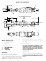
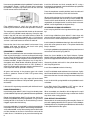
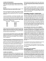
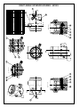
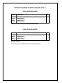
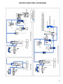
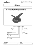
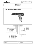
Operation & Service Manual
823220
11/24/03
140QGDA-RA-SU-MS &
140QDA-RA-SU-MS
RIGHT ANGLE DRILLS
For additional product information visit our website at www.coopertools.com
N O R T H A MER ICA
EUROPE
CooperTools
P.O. Box 1410
Lexington, SC 29071-1410
Recoules Operation
Zone Industrielle - B.P.28
Avenue Maurice Chevalier
77831 Ozoir-la-Ferriere Cedex, France
1
Safety Recommendations
For your safety and the safety of others, read and understand
the safety recommendations and operating instructions.
Always wear protective equipment:
!
WARNING
Impact resistant eye protection
must be worn while operating
or working near this tool.
For additional information on eye and face protection, refer to
Federal OSHA Regulations, 29 Code of Federal Regulations, Section 1910.133., Eye and Face Protection, and American National
Standards Institute, ANSI Z87.1, Occupational and Educational Eye
and Face Protection. Z87.1 is available from the American National
Standards Institute, Inc., 11 West 42nd Street, New York, NY 10036.
!
CAUTION
!
CAUTION
• Quackenbush drills are designed to operate on 90psig (6.2 bar)
air pressure. Excessive air pressure can increase the loads and
stresses on tool parts and drills, and may result in breakage. The
installation of a filter-regulator-lubricator in the air supply line is
highly recommended.
• Before removing a tool from service or changing drill bits, make
sure the air line is shut off and drained of air. This will prevent the
tool from operating if the throttle is accidently engaged.
• Cutting tools used with these Quackenbush drill motors are sharp.
Handle them carefully to avoid injury.
!
CAUTION
Before mounting any positive feed drill, check the lock screws in the
tooling fixture and drill bushing. Make sure both are in good condition
and securely tightened.
Lock Screws
Tool Nose
Personal hearing protection is
recommended when operating
or working near this tool.
Hearing protection is recommended in high noise areas, 85 dBA or
greater. The operation of other tools and equipment in the area,
reflective surfaces, process noises and resonant structures can
substantially contribute to and increase the noise level in the area.
For additional information on hearing protection, refer to Federal
OSHA Regulations, 29 Code of Federal Regulations, Section 1910.95,
Occupational Noise Exposure, and American National Standards
Institute, ANSI S12.6, Hearing Protectors.
WARNING
Positive feed drills can exert high torques and high thrust loads. If
failure of the lock screws or drill bushing occurs, the drill may
suddenly spin and back away from the drill fixture.
Warning Labels
COMPLETE LABEL
KIT - 641026
!
WARNING
• Wear impact resistant eye protection.
• Hearing protection is recommended.
• Avoid contact with rotating spindle or cutter.
• Wear respirator as necessary.
• Exposure to repetitive work motion
and/or vibration can injure your hands
and arms.
203246
203246
2
382788
CAUTION
!
Read operating
instructions before
using tool.
203245
382788
To begin drilling cycle, push the
green "DRILL" button. To stop the drill
before the completion of the drilling
cycle, push the red "STOP" button.
To stop rapid advance,
release rapid advance lever.
The warning labels found on these tools are an essential part of this
product. Labels should not be removed. Labels should be checked
periodically for legibility. Replace warning labels when missing or
when the information can no longer be read. Replacement labels
can be ordered from the manufacturer.
! CAUTION
Follow good machine shop
practices. Rotating shafts and
moving components entangle
and entrap, and may result in
serious injuries. Never wear
long hair, loose-fitting clothes,
gloves, ties, or jewelry when
working with or near a drill of
any type.
Do not wear loose fitting clothes,
long hair, gloves, ties or jewelry.
Tooling Fixture
DO NOT ENGAGE RAPID
ADVANCE AND GREEN "DRILL"
BUTTON AT SAME TIME.
To rapid advance the drill, rotate
rapid advance lever clockwise.
!
Standard Threaded
Drill Bushing
203245
Safety Recommendations
!
CAUTION
The spindle on right angle positive feed drills retracts at a much
faster rate than it feeds. Care should be taken to avoid entrapment.
Nose pieces usually used with these drills are generally slotted for
visibility and access to chuck, cutter, and retract stop adjustments.
A spindle guard should be used when operating tool. Spindle
guards in one inch increments are available to accommodate any
length spindle. Slotted spindle guards are available for tools with
fluid swivels.
!
WARNING
Some individuals are susceptible to disorders of the hands and arms
when exposed to tasks which involve repetitive work motions. Those
individuals predisposed to vasculatory or circulatory problems may
be particularly susceptible. Cumulative trauma disorders such as
carpal tunnel syndrome and tendinitis can be caused or aggravated
by repetitious, forceful exertions of the hands and arms. These
disorders develop gradually over periods of weeks, months, and
years.
Avoid
Extension
OK
Neutral
Avoid
Flexion
Avoid
Radial Deviation
OK
Avoid
Neutral
Ulnar Deviation
• Tasks should be performed in such a manner that the wrists
are maintained in a neutral position, which is not flexed,
hyperextended, or turned side to side.
• Stressful postures should be avoided and can be controlled
through tool selection and work location.
Keep fingers and hands away
from this area when handling
or operating tool.
!
WARNING
Wear respirator where
necessary.
Drilling or other use of this tool may produce hazardous fumes and/
or dust. To avoid adverse health effects utilize adequate ventilation
and/or a respirator. Read the material safety data sheet for any
cutting fluids or materials involved in the drilling process.
!
WARNING
• Most dusts are combustible. See material safety data sheets for
combustibility of a specific dust.
• Non ferrous metal dusts are particularly hazardous.
Examples: Aluminum, Magnesium, Titanium, Zirconium
(Never collect Magnesium in a dry dust collector)
• Never collect spark generating material in the same dust collector
with combustible material.
Examples: Collecting both steel and Aluminum dust or Steel and
Titanium dust.
• Never use flammable finishing lubricants.
Any tool operator should be aware of the following warning signs and
symptoms so that a problem can be addressed before it becomes a
debilitating injury. Any user suffering prolonged symptoms of tingling, numbness, blanching of fingers, clumsiness or weakened
grip, nocturnal pain in the hand, or any other disorder of the
shoulders, arms, wrists, or fingers is advised to consult a physician.
If it is determined that the symptoms are job related or aggravated
by movements and postures dictated by the job design, it may be
necessary for the employer to take steps to prevent further occurrences. These steps might include, but are not limited to, repositioning the workpiece or redesigning the workstation, reassigning workers to other jobs, rotating jobs, changing work pace, and/or changing
the type of tool used to minimize stress on the operator. Some tasks
may require more than one type of tool to obtain the optimum
operator/tool/task relationship.
The following recommendations will help reduce or moderate the
effects of repetitive work motions. The operator of any drill should:
• Use a minimum hand grip force consistent with proper control
and safe operation
• Keep body and hands warm and dry
• Avoid anything that inhibits blood circulation
— Smoking Tobacco
— Cold Temperatures
— Certain Drugs
• Avoid awkward postures
• Keep wrists as straight as possible
• Interrupt work activities, or rotate jobs to provide
periods free from repetitive work motions.
3
MAJOR TOOL CONTROLS
~21/32
(17 MM)
~1-11/16
(43 MM)
~2-19/32
(66 MM)
3
9
~1-13/32
(36 MM)
5
~5-3/8
(137 MM)
7
1
~18-21/32 -FOR 1000 RPM, 580 RPM & 380 RPM
(474 MM)
19 7/8 -FOR 260 RPM, 200 RPM, 150 RPM & 95 RPM
(505 MM)
6
~2-19/32
(66 MM)
~3-3/8
(86 MM)
~2-9/16
(66 MM)
3/8-18 NPT
2
1-20 UNEF-2A THD
4
8
MAJOR TOOL CONTROLS
1
2
3
4
5
6
7
8
9
Emergency Stop Button
Rapid Advance Lever
Drill Button
Retract Stop Collar
Manual Retract Lever
Adjustable Depth Stop
Rear Spindle Guard
Signal Valve
Throttle Piston
should be connected to the 1/2" in. hose. Quick disconnect
couplings (if used) should have flow capacity ratings exceeding 60 SCFM.
LOW PRESSURE:
This drill will shut-off automatically (while drilling or when
retract begins) if the pressure at the tool inlet drops below
65 psig (4.5 bars). Manual restart is required. The drill will not
continue to run when the green drill button is released if the
pressure at the tool inlet is low.
HIGH PRESSURE:
AIR SUPPLY
AIR PRESSURE, HOSES, AND COUPLINGS:
This tool is designed to operate on 90-110 psig (6.2-7.6 bars)
supply pressure using a 1/2" hose up to 20 ft. in length. If
additional hose is needed, a 5/8" or larger diameter hose
4
This drill shuts off automatically at the end of the retract cycle.
If the pressure at the tool inlet is over 115 psig (7.9 bars) the
tool may continue to retract, jamming the retract stop collar into
the housing cover causing the tool to either stall or shear the
shear pin.
If the tool has been shipped recently, been in storage, or
repaired or disassembled; it should be run (without spindle)
through a "tool crib check" of functions (See Below).
5. With air supply on, fully depress the rapid advance lever 2.
Motor should runs and spindle feed gear (threaded I.D.) must
not rotate. Spindle drive gear (splined l.D.) rotates. If the motor
runs and the splined ID does not rotate, verify that the shear pin
is whole and intact.
EMERGENCY STOP—Depressing the red emergency stop
button 1 will stop the tool, except when the rapid advance mode
is being utilized. Releasing the rapid advance lever 2 will stop
the tool during rapid advance.
6. Release rapid advance lever 2 and press green drill button
3 all the way in. Motor starts. Release green drill button 3. Motor
continues to run. Both gears should (splined and threaded)
rotate.
RAPID ADVANCE—Depressing the rapid advance lever 2 will
bring the cutting tool to the work surface faster than the regular
feed rate.
7. Depress manual retract lever 5 and release. An audible
"snap" indicates the retract valve is shifting as desired. Spindle
feed gear (threaded l.D.) stops rotating.
DRILLING—Press the green drill button 3 firmly and release
it to start the cycle. The cutter will feed to a predetermined
depth, dwell, and then retract. The drill motor will shut off
automatically at the end of the retract stroke. The cutter may
be manually retracted at any time by depressing the manual
retract lever 5.
8. Depress signal valve 8 with screwdriver and release. Motor
stops and retract valve must reset (manual retract lever 5
should rise). Depress red emergency stop button 1 slowly.
There should be no venting of air as the emergency stop button
1 is depressed.
OPERATING INSTRUCTIONS
IMPORTANT: The spindle retracts at a much faster rate than
it feeds. Care should be taken to avoid entrapment.
Do not hold the drill button down during the retract cycle —this
prevents "motor stop" and will jam the tool.
DEPTH ADJUSTMENT:
DEPTH COLLAR—Has three (3) holes for adjusting depth in
increments of .004". Tighten lock screw after each depth
adjustment. Tip of lock screw must go into a spindle slot.
IMPORTANT NOTE: To insure maximum repeatability, the
work surface, fixtures, and depth stop must be cleared of any
chips or foreign material before beginning the next hole.
Always replace the rear spindle guard after making a depth
adjustment.
TOOL CRIB CHECK
1. With air supply shut off, remove rear spindle guard.
2. Remove depth stop 6 (left hand threads).
WARNING: Keep hands and clothing clear of rotating spindle,
turn air supply on and use rapid advance to remove spindle.
3. Shut off air supply pressure.
4. Depress 5/16" diameter steel end of throttle piston 9. The
throttle piston must spring return quickly when released.
9. Press green drill button 3 and release. Motor starts. Press
emergency stop button 1 . Motor stops.
10. Inspect the manual retract lever 5. It should move freely
when depressed and return quickly when released. The thumb
pad is adjusted at the factory to be even with the top of the
head.
Do not proceed with test if steps 1 through 9 indicate malfunction.
WARNING: Keep hands and clothing clear of rotating spindle.
11. Turn air supply off. Using tool 382593, install spindle (with
retract stop collar 4 locked in place and tapered side of stop
collar 4 is toward the head). Remove tool 382593. Turn of air
supply. Depress the green drill button 3. Tool will start. Depress the manual retract lever 5. The spindle will retract fully
into the head and the motor will stop automatically. Depress
the emergency red stop button 1 slowly. There should be no
venting of air when the emergency stop button 1 is depressed.
12. Screw depth stop 6 (left hand threads) onto the rear end of
the spindle and lock in place. Rapid advance until depth stop
6 comes into contact against the back of the thrust bearings in
drill head. The spindle should stop rotating and the rapid
advance overload clutch should "chatter". The manual retract
lever 5 should not drop as the clutch "chatters". Release the
rapid advance lever 5.
13. Depress green drill button 3 and release. Motor starts.
Retract lever 5 drops and spindle retracts automatically to full
retract position. Motor will stop automatically. Verify that the
manual retract valve has reset properly.
14. Replace rear spindle guard.
NOTE: If the tool does not function properly, check for excessive leakage in the air control system as follows.
5
LOCATING EXCESSIVE LEAKAGE IN THE A.C.S.
Most air leaks create a hissing noise that is easily heard if
background noise is not too loud. With the air supply on, place
a small punch against the bottom end of the throttle piston
(place the punch through the hole in the throttle cylinder end
cap). This will prevent the throttle from opening if you push
firmly. Now push the drill button a small amount until the A.C.S.
is holding pressure. Remove the punch. You will now be able
to locate leaking air audibly. Some leakage at the retract valve
is normal. By lifting the retract lever you can detect excess
leakage at the signal valve, or in the retract piston air circuit.
Missing "O"-rings or a damaged signal valve are the most
common sources of excessive leakage.
INSTALLING A SPINDLE:
Run a "Tool Crib Check" (see page 5)
Important: Retract stop collar 4 629375 must be in place and
locked on the spindle. Install the spindle in the spindle drive
gear 622950 and use spindle "in & out" tool 382593 to push the
spindle "in". Depress the green drill button 3 to start the motor
and depress the manual retract lever 5. The spindle will retract.
Release the green drill button 3. The spindle will continue to
retract until the retract stop collar 4 depresses the signal valve
8 and the tool will automatically shut off. Note: When the retract
stop collar 4 is near or touching the signal valve 8; Do not press
the green drill button 3; as this will prevent tool shutoff and jam
the spindle into the head. Install depth stop collar 6 617962 and
adjust for proper depth.
CHANGING FEED GEARS:
Remove (left hand threads) the adjustable depth stop 6 from
the rear of the spindle. Using the spindle "in & out" tool 382593
to support the front of the spindle, depress the rapid advance
lever 2 and feed the spindle forward until the spindle feeds
itself out of the spindle feed gear. Release the rapid advance
lever, shut off the air supply, and pull the spindle out of the
spindle drive gear. Remove the side hose assembly. Unscrew
the head from the clutch housing and remove the bevel gear
622947 and bearing 847095. Remove the two small cap
screws in the thrust pack body. Unscrew the two large screws
864415 holding the thrust pack body to the head assembly.
Note: Clamping the tool in a vise will make removal of the two
large screws more convenient. Remove the thrust pack body.
Remove the thrust pack case 629344 (with bellville springs).
Remove the fourteen balls 629352. Unscrew and remove the
two screws 617166 in the bottom of the head assembly.
Remove the right angle head cover 629343. The gears will
come out with the cover. Remove the small retaining ring
847653 from the feed/retract piston shaft 629380. Do not over
expand the retaining ring. Press the shaft out of the differential
feed gear bearing 863582. Refer to the feed chart on assembly
drawing for the appropriate feed gears. The right angle head
should be securely clamped in the vise and compressed so
that the two cap screws 864415 can be firmly tightened.
SHEAR PIN MAY SHEAR BECAUSE:
1. Motor doesn't stop at full retract, or the retract valve did not
reset. Retract collar 4 jams against the bearing 622400. Pin
shears.
6
2. Packed chips or dull cutter may overload the spindle. Feed
rate may be too high. Drilling or reaming may be beyond the
torque capability of this right angle drill. Pin shears.
3. Improper adjustment of manual retract lever may prevent
automatic retract when the depth stop 6 contacts the drill head.
If this occurs possible damage to gears and shearing of pin will
result.
4. Gear teeth have broken, spindle threads have been damaged, or parts inside the drill head have failed.
CAUSES 1 & 2 DO NOT REQUIRE DISASSEMBLY OF
DRILL HEAD:
1. For cause 1 spindle may be freed in this manner:
A. Turn off air supply.
B. Remove tool from drilling fixture.
C. Rotate spindle with wrench (CCW from rear). . .
opposite drilling direction 2 or 3 turns. This will
require high torque.
D. When spindle is free, replace shear pin. Supply air
pressure and rapid advance the spindle out of the
drill head.
E. Correct malfunction and run "Tool Crib Check".
2. For cause 2 spindle may be freed in this manner:
A. Turn off air supply.
B. Remove tool from drilling fixture.
C. Correct torque overload problem.
D. Replace shear pin.
E. Return tool to service.
3 and 4 require disassembly, cleaning, inspection, and replacement of damaged parts inside the drill head. All parts
inside the drill head should be washed and re-greased. When
cause of malfunction is corrected, run "Tool Crib Check".
SHEAR PIN INSTALLATION AND REMOVAL
Align the "V" notch on the shaft with the "V" notch on the bevel
gear. Insert a 3/32" diameter pin into the hole on the side of the
bevel gear and into the shaft to maintain shear pin hole
alignment while installing or removing the shear pin.
CHANGING THRUST PACKAGE:
Remove the upper block assembly following the instructions
for changing feed gears.
Lift out the spring washers, the thrust race and any spacers
from the thrust package. The retract thrust is changed by the
addition or removal of spacers under the thrust race. Install the
correct number of spacers. Reinstall the spring washers.
Reinstall the upper block and side hose assembly.
Spacers
Note: Spring washers must be stacked exactly as shown. Two
down, two up, two down, two up. One or two spacers may be
included in the spring stack and must be installed under the
thrust race against the spring case. Align the bore of the spring
washers to clear the 1/2" O.D. of the spindle.
LUBRICATION:
An automatic in-line filter-lubricator is highly recommended.
This will supply the tool with clean, lubricated air; keep it in
sustained operation; and increase tool life.
The in-line lubricator should be regularly checked and filled
with a good grade of 10W machine oil. In the event an in-line
lubricator is not used, the tool should be disconnected from the
air supply several times daily and several drops of oil poured
into the tool's air inlet bushing.
The right angle drill head should receive a generous amount of
"Lubriplate #907" grease every fifteen (15) to twenty-five (25)
hours of "actual motor running" time through the two (2) flush
type grease fittings in the right angle head. "Lubriplate #907"
may be purchased in a 5 gallon can using Part No. 107210.
GENERAL MAINTENANCE:
Air control system filter 382505 located in the handle 382480
should be replaced every 2000 drilling cycles or when low air
control system pressure is suspected.
Spindle threads should be blown clean and lubricated every
100 drilling cycles.
DISASSEMBLY—DRILL HEAD:
Remove (left hand threads) the adjustable depth stop 6 from
the rear of the spindle. Using the spindle "in & out" tool 382593
to support the front of the spindle, depress the rapid advance
lever 2 and feed the spindle forward until the spindle feeds
itself out of the spindle feed gear. Release the rapid advance
lever, shut off the air supply, and pull the spindle out of the
spindle drive gear. Remove the side hose assembly. Unscrew
the head from the clutch housing and remove the bevel gear
622947 and bearing 847095. Remove the two small cap
screws in the thrust pack body. Unscrew the two large screws
864415 holding the thrust pack body to the head assembly.
Note: Clamping the tool in a vise will make removal of the two
large screws more convenient. Remove the thrust pack body.
Remove the thrust pack case 629344 (with bellville springs).
Remove the fourteen balls 629352. Unscrew and remove the
two screws 617166 in the bottom of the head assembly.
Remove the right angle head cover 629343. The gears will
come out with the cover.
DISASSEMBLY—RAPID ADVANCE CLUTCH:
Firmly clamp the gear case in a vise. Use a pin spanner wrench
to turn the positioning ring 629307 and a appropriate wrench
to turn the clutch housing 629602. NOTE: The positioning ring
has right hand threads and the clutch housing has left hand
threads. The clutch mechanism can be disassembled by
removing the retaining ring 867924 which retains the spring
and washer on the outside and the retaining pin on the inside.
DISASSEMBLY—GEAR TRAIN:
Clamp the governor housing in a vise and unscrew the gear
case from the motor housing. Slip the 1st reduction spider and
bearing out of the gear case.
For a double reduction gear case, clamp the gear case in a vise
and remove retainer ring 864240 with two screwdrivers. Push
the second reduction spider and bearing out of the gear case.
Turn the gear case over and remove the retaining ring 844364
and bearing 843615.
After removing the spider bearings with a suitable bearing
puller, the idler gears may be removed by driving the idler gear
pins out the rear of the spiders. The pinion gear 864239 used
in 4200 rpm, 3000 rpm and 620rpm power units can then be
removed from the 1st reduction spider.
DISASSEMBLY - MOTOR
Slide the exhaust deflector off the motor housing. Clamp the
governor housing in a vise and unscrew the clamp ring
629318. Press down on the rotor shaft while sliding the motor
housing and clamp ring off the motor. Lift the motor out of the
governor housing. Hold the motor cylinder and use a soft
hammer to tap the rotor out of the front bearing 844772. Clamp
the rotor shaft in a vise (be careful not to damage the gear
teeth) and unscrew the governor assembly (or, for nongoverned tools, the rotor nut). Be careful to keep the rotor collar
that was in the rear bearing plate separate from the one used
to space the governor body.
The governor can be disassembled by removing the two small
groove pins 864821 and pushing out the two dowel pins
867388 that retain the governor weights.
DISASSEMBLY - GOVERNOR HOUSING
Remove the two cap screws 382524 that hold the handle to the
governor housing. Remove pin 843280 from the bore. Remove retaining ring 204775 which retains rapid advance plug
629315 and spring 844869. Gently tap the housing on a
wooden bench top to remove piston 629317.
Unscrew the two Pressure Caps (382380) and remove the
springs 843250, balls 812156, vent piston 629320, and two
pins 843280. Remove retaining ring 613126 and slide rapid
advance cylinder 629321 out of the housing.
DISASSEMBLY— HANDLE
Unscrew plug 864387 and remove drill button spring 622833.
Depress the drill button 382484 and use a 1/8" diameter rod to
unscrew button guard 382671. Unscrew inlet bushing 867758
and remove spring 863072 and throttle valve 202365.
7
Unscrew end cap 382668 and spring 382489. Push out throttle
piston 382677. Screw a 1/4-20 cap screw into the metering
seat 382491. Clamp the cap screw in the vise and use a soft
faced hammer to drive the handle off.
Install the drill button and shaft assembly 381171, using a
thread retaining compound. Install the drill button spring 622833
and plug 864387 with O-ring.
Press the stop button assembly 381243, into the handle until
the shoulder on the bushing is flush with the handle.
When installing the check valve assembly, the spring 382488,
should be installed with the small coil up. Use a slender rod.
Place the 3/16" steel ball 842161, on the small coil and the Oring 844302, on the top of the ball. Install the check valve seat
382487, and O-ring 844303, and tighten firmly.
Filter 382505 located in 13/32" dia. hole adjacent to the
metering seat should be checked and replaced if necessary.
The emergency stop button 381243 should not be removed
unless the O-ring 844301 needs replacing. Clamp the stop
button in the vise and use a soft faced hammer to drive the
handle off. Tap the bushing 202354 with a 1/4-20 thread.
Screw a 1/4-20 bolt into the bushing, clamp the bolt in the vise
and use a soft faced hammer to drive the handle off.
Unscrew the check valve seat 382487 and remove O-ring
844302, 3/16" steel ball 842161 and check valve spring
382488. NOTE: Spring is very small.
REASSEMBLY— GENERAL
The tool is reassembled in the reverse order of disassembly.
Clean all parts thoroughly in a solvent and inspect for damage
or wear. Check all bearings for wear which can be detected by
excessive end play and/or roughness which would indicate a
brinelled condition. Inspect and replace any O-ring that is
damaged or worn. Rotor blades should be replaced at every
repair cycle or if they measure less than 7/32" (5.56mm) at
either end. All gear teeth, bearings, and pins should receive a
close inspection and be replaced if necessary.
All gears and bearings in the planetary gear train should
receive a generous amount of NLGI 2-EP grease during
reassembly.
All gears and bearings in the right angle drill head should
receive a generous amount of "Lubriplate #907" grease during
reassembly.
Lubricate all O-rings during reassembly with 10W machine oil.
HANDLE REASSEMBLY:
Insert throttle piston 382677 (with O-rings) into throttle piston
cylinder 382676. Replace spring 382489 and end cap 382668.
Rotate the throttle piston 382677, to line up the slot for the
throttle valve 202365. Replace spring 863072, O-ring, and inlet
bushing 867758. If the screen in the inlet bushing is torn or
clogged, replace the inlet bushing.
Insert spring 382489, O-ring 844307, and latch piston 382490,
into handle. Line up the air ports in the metering seat 382491,
and handle 382480, and tap the metering seat into the handle
until the shoulder on the seat is flush with the surface of the
handle. Use a 1/4-20 bolt to tap or press the metering seat.
8
GOVERNOR HOUSING REASSEMBLY:
Install snap ring 204776 in the large bore with the gap at the
top.
Install 0-rings 615645 on piston 629317. Lube 0-rings with
grease and insert piston, solid end first, into piston bore until
the small hole is visible through slot in the main bore.
Install a dowel pin 843280 round end up in the small hole in the
piston with some grease to retain it. The piston should slide
freely in the bore.
Install spring 844869 and plug 629315 into the piston bore and
secure them with retaining ring 204775.
Mount the Lever 382503 to the Rapid Advance Cylinder
629321 with Screw 382504. Mount the Lever so that the thumb
pad is on the opposite side from the two cutouts on the cylinder.
Grease the cylinder and install it in the cylinder bore. Secure
with Snap Ring 613126.
Install Screw 386090 into back of housing.
Install Pins 843280, round end down into valve bores. Lightly
lube Piston 629320 and install it on the pin 834280 in the valve
bore nearer the lever. Insure that the piston moves freely in the
bore.
Install a ball 812156, spring 843250 and cap 382380 in each
valve bore.
Install Right Angle Fitting 382664 in NPT port on side of
housing. Align it to face the front of the housing.
When assembled, one should be able to depress the rapid
advance lever till it hits the positive stop, and the lever should
snap back to the starting position.
FINAL REDUCTION ASSEMBLY:
Reassemble in the reverse order of disassembly. Grease all
parts with a good grade of NLGI 2-EP grease. For the 4200rpm
and 620 power units, the pinion gear 864239 must be installed
in the spider before the idler gears.
POWER UNIT REASSEMBLY:
Apply a thin film of grease to both sides of gasket 382492.
Assemble handle subassembly to governor housing subassembly with the gasket between. Secure with two screws
382524 .
MOTOR:
Measure the length of the cylinder 629324. Size four rotor
blades 625577 .005 inches shorter than the cylinder.
Measure the length of the cylinder and the length of the body
of the rotor. Subtract the rotor body length from the cylinder
length and divide the difference by two. This is the rotor end
clearance.
Install bearing 847095 in rear bearing plate 629325. Lightly
load the inner race of the bearing. Using a depth micrometer,
measure the distance from the flat face of the bearing plate to
the inner race. Add the rotor end clearance to get the rotor
collar thickness. Select the rotor collar that most closely
matches the calculated thickness.
Rotor Collar
Thickness Part Number
.1850
869260
.1860
869261
.1870
869262
.1880
204778
.1890
843913
Place the rotor collar selected on the threaded end of the rotor
with the large chamfer facing the rotor body. Install set screw
867086 in rotor with hex into hole first. For the 1100 rpm motor
(380 rpm spindle) and the 230 rpm motor (75 rpm spindle) the
set screw must be inserted normally.
Insert the governor stem 629329 into governor spider 865686
from the non-threaded end. Place the two governor weights
865663 in the spider slots and insert twogovernor weight pins
867388. Press the two lock pins 864821 in the small holes to
retain the weight pins.
Place the rear bearing plate with the bearing in place on the
threaded end of the rotor. Install Rotor collar 843913, to act as
a spacer, and the Reversing Valve 629327 (with the small
pocket facing away from the bearing plate) against the rear
bearing plate. Insert the governor spring 867084 into the rotor.
Screw the governor assembly onto the rotor and tighten.
Lubricate the rotor blades with 10 wt. oil and insert them into
rotor slots. Slide cylinder 629324 over the rotor and insert the
alignment pin in the cylinder into the hole in the rear bearing
plate. Install front bearing plate 864235 and press front bearing
844772 into place. While lying in a V-block, the rotor should
turn with no indication of dragging or rubbing.
POWER UNIT ASSEMBLY:
Insert the motor, governor end first, into the governor housing.
The reversing valve should lie on the large retaining ring in the
housing bore, and the pin in the reversing piston should
engage the small pocket on the face of the reversing valve. The
alignment button on the rear bearing plate should fit in the small
cutout at the top of the governor housing bore.
Slide the motor housing 629319 over the motor. Align the pin
in the motor housing to the hole in the governor housing. Clamp
the motor housing to the governor housing using clamp nut
629318.
Install two muffler elements 629323 in exhaust deflector
629322, covering the exhaust slots. Install two muffler elements 203632 inside of the 629323 elements. Of the three
cavities in the exhaust deflector, the middle one remains
empty. Install 0-ring 617754 in the groove. Slide the exhaust
deflector over the motor.
REASSEMBLE AND INSTALL THE GEAR TRAIN:
fOR THE 4200rpm, 3000rpm and 620rpm power units, the
pinion gear 864239 must be installed in the spider before the
idler gears. Plug the right angle fitting and run the power unit.
The output RPM should be no more than 10% above or below
the rated speed. Adjust governor if necessary. For 1100 rpm
motor (380 rpm spindle) and 230 rpm motor (75 rpm spindle),
the power unit must be disassembled and the governor removed to adjust the set screw. Turn the screw counterclockwise to increase motor speed, and clockwise to decrease
motor speed. For all other power units,remove the gear train
and use a long Allen wrench to turn the governor set screw.
Turn the screw clockwise to increase motor speed, and
counter clockwise to decrease motor speed.
RAPID ADVANCE OVERLOAD CLUTCH ASSEMBLY:
Insert two 616503 bushings into 629312 spindle (The bushings might be slight press fits in the spindle.) Lubricate the
large spline on the spindle and install 382536 Clutch Jaw. The
clutch jaw should slide freely. Install 629309 driving clutch jaw
and secure with 629310 retaining pin. Pin should sit flush with
or slightly below the spindle surface. Install 204349 spring,
852264 washer and 867924 retaining ring. With the spline
clamped in a vise, use a torque wrench to turn the hex on the
driving jaw. The clutch should trip between 3 and 5 inch
pounds. If the clutch torque is too light, disassemble the unit
and press the shaft of the driving jaw in to shorten its length by
.020 inches. Install 203339 Belleville Spring Washer over the
small spline of the clutch spindle with the dished side towards
the clutch.
Thread 629307 Positioning Ring onto 629302 Clutch Housing
with the holes in the ring towards the smaller threads.
If the subassembly is to be checked into stock or sent out as
spare parts, place both components in a plastic bag to keep
them together.
RIGHT ANGLE HEAD ASSEMBLY:
BOTTOM COVER PLATE:
Install bearing 622400 in the large bore of the right angle head
cover 629343. Press the bearing 847609 into the differential
drive gear 629367. Insert gear post 629365 into the bore of the
bearing and press the post into the housing cover. Press the
spindle drive gear 622950 into the bore of bearing 622400.
Press the idler gear post 629359 into the head cover. Insert the
signal valve shaft 629355 and the spring 867895 into the
angled bore of the head cover. Install plug 843434. Insert
bearing 847609 into the small bore at the end of the plate.
9
Install bearing 617980 and two retaining rings 619016 into
idler gear 622948. Slip the idler gear on the idler gear post.
Slide idler gear spacer 629351 onto the idler gear post.
Install retaining ring 629387 in the large bore of the housing.
Align the gap in the retaining ring towards the gear stop.
Grease the ball race on the differential feed gear. Install
fourteen balls 629352 in the ball race of the spindle feed gear.
Press shear pin gear 627628 into bearing 629353. Insert
pinion 629376 into the shear pin gear and install shear pin
629377. Insert the small diameter of the pinion into the bore of
bearing 847609.
Grease the outside and the ball race of thrust pack case
629358. Set the thrust pack case on the spindle feed gear and
rotate it to make sure the balls are properly aligned in the races.
HOUSING:
Install 0-ring 8443 05 in the stop collar in housing 629384 and
lubricate with grease.
Install the proper number of spacers 629344 for the head being
built. (High thrust - 2, Standard thrust - 1, Low thrust - 0) Install
883975.
Insert bearing 863582 into the differential feed gear and
secure with retaining ring 844568.
Install eight Bellvilles 629372 in the thrust pack case. The
bellvilles should be stacked in pairs. The first and third pairs
should be set with the dished side facing up. The second and
fourth pairs should face down.
Install spring 832595 and feed/retract piston 629380 into right
angle head housing 629384. Compress the spring and install
the differential feed gear on the shaft of the feed/retract piston.
The bearing should have a press fit on the piston shaft, and the
gear should be installed with the snap ring facing the small
diameter end of the shaft. Install washer 623538 and secure
with retaining ring 847653.
THRUST PACK BODY:
Clean and lubricate the valve bore of the thrust pack body
627851. Insure that the retract valve 382333 slides freely in the
bore. Install 0-ring 844306 on the retract valve and grease the
valve and 0-ring. Install spring 382540 on the end of the retract
valve. Insert the retract valve, spring end first, into the bore in
the thrust pack body. Thread air tube fitting 629366 into the
valve bore and tighten.
Lubricate retract sensor piston 629378 and insert it stepped
side first into the thrust pack body. Rotate the piston so that the
piston does not protrude into the thrust pack bore.
Insert spring 843030 into the blind hole in the recess for the
retract lever. Install retract lever 629374, Retract trigger 629379
and slotted pin 619154. Insure that the lever and trigger move
freely.
FINAL ASSEMBLY OF THE HEAD:
Lubricate the small diameter of the feed/retract piston and the
teeth of all the gears on the cover plate and the differential feed
gear with grease.
Place the housing over the bottom cover plate. The bottom
face of the housing should meet the face of the cover plate.
Secure with two screws 617166.
Install 0-ring 844310 on the feed/retract piston and lubricate
with grease.
Grease the teeth and bottom surface of the spindle feed gear,
and install in the head.
10
Place 0-ring 844301 on top of the idler gear post.
Place the thrust pack body on top of the head assembly. Insure
that the retract piston is aligned such that the small step will
land on the thrust pack case. Guide the feed/retract piston into
the bore in the thrust pack body. Install two screws 617166,
382539 , and 617396 finger tight. Tighten the two larger screws
alternately to pull the thrust pack body evenly to the head
assembly. Tighten the two smaller screws.
Temporarily insert a spindle into the differential drive gear and
insure that everything turns freely and evenly.
Adjust the small set screw in the retract lever to set the pad of
the lever even with the top of the thrust pack body. Secure with
Loc-Tite 290.
Grease the ball race of stop collar thrust race 629356. Place
eighteen balls 844265 in the race. Install the thrust race and
guard coupling 629357 in the thrust pack body.
Press bearing 847095 onto driving bevel gear 622947. Grease
the gear teeth and insert the gear into the housing.
FINAL ASSEMBLY:
Screw the Rapid advance clutch housing into the right angle
head and tighten. Insert the clutch into the bevel gear in the
right angle head. Unscrew the positioning ring until one or two
threads are showing. Thread the clutch housing into the gear
case making sure that the hex of the clutch is inserted into the
gear train spider. Thread the clutch housing until it bottoms out
against the gear case. Unscrew the clutch housing until the top
of the right angle head is aligned with the top of the green drill
button. With the power unit clamped in a vise, hold the clutch
housing with a wrench and tighten the positioning ring. Install
the side hose.
RIGHT ANGLE HEAD
55
2
49
1
B
B
26
1
A
ADJUST SET SCREW IN ITEM 27 SO THAT
THESE TWO SURFACES ARE FLUSH.
27
1
48
1
22
1
1
1
4
1
44
2
C
C
A
SCALE
1.0
11
RIGHT ANGLE HEAD
43
1
41
1
C-C
SECTION
23
1
25
1
54
1
50
1
47
1
51
1
SECTION
12
42
1
B-B
5
1
6
1
33
1
32
1
2
1
53
14
20
2
21
1
19
1
52
8
29
18
28
1
31
1
34
1
35
1
36
1
3
1
37
1
40
1
8
1
38
1
11
1
9
1
39
1
SECTION
13
1
A-A
12
2
24
1
10
1
11
1
14
1
18
1
17
1
7
1
45
1
46
1
15
1
16
1
RIGHT ANGLE HEAD
13
PARTS LIST FOR RIGHT ANGLE HEAD
14
PART NAME
TABEL 1
QTY.
ITEM
PART NO.
1
2
629384
629387
HOUSING, RIGHT ANGLE HEAD
RING, RETAINING (1-3/16 UR SERIES)
1
1
3
4
844305
629343
RING, O (.070 CROSS SECTION)
COVER, RIGHT ANGLE HEAD
1
1
5
6
622400
629640
BEARING, BALL
GEAR, SPINDLE DRIVE
1
1
7
847609
BEARING, BALL
1
8
9
629365
629367
POST, GEAR
GEAR, DIFFERENTIAL DRIVE
1
1
10
11
629359
617980
POST, IDLER GEAR
BEARING, BALL
1
1
12
13
619016
622948
RING, RETAINING
GEAR, IDLER
2
1
14
629351
SPACER, IDLER GEAR
1
15
16
629353
627628
BEARING, BALL
GEAR, DRIVEN
1
1
17
18
629376
629377
PINION
PIN, SHEAR
1
1
19
20
629358
629344
CASE, THRUST PACK
SPACER
1
21
22
883975
627851
RACE, THRUST
BODY, THRUST PACK
23
629378
PISTON, RETRACT SENSOR
1
24
25
844301
629379
RING, O (.070 CROSS SECTION)
TRIGGER, REVERSE
26
629366
FITTING, AIR TUBE
27
28
29
31
32
629374
629356
844265
629357
SEE TABLE 1
LEVER, RETRACT
RACE, STOP COLLAR THRUST
BALLS
COUPLING, GUARD (incl. 883975)
GEAR, SPINDLE FEED
1
1
1
1
1
18
1
1
33
SEE TABLE 1
GEAR, DIFFERENTIAL FEED
1
34
35
36
863582
844568
623538
BEARING, BALL
RING, RETAINING
WASHER, FLAT
1
1
1
37
847653
RING, RETAINING
1
38
39
629380
844310
PISTON, FEED/RETRACT
RING, O
1
1
40
41
832595
629355
SPRING, RETURN
SHAFT, SIGNAL VALVE
1
1
42
43
843434
867895
PLUG, PRESSURE
SPRING, RESET PIN
1
1
44
617166
SCREW, SFCHC
2
45
46
847095
622947
BEARING, BALL
GEAR, BEVEL DRIVING
1
1
47
48
844306
617396
RING, O (.070 CROSS SECTION)
SCREW, SHC (6-32UNC)
1
1
49
50
382539
843030
SCREW, SHC (6-32UNC)
SPRING, SOCKET LOCK PIN
1
1
51
382540
SPRING, RETRACT VALVE
1
52
53
629372
629352
WASHER, BELLEVILLE SPRING
BALL
8
14
54
844234
PIN, SLOTTED SPRING
1
55
56
864415
844833
SCREW, SHC (10-24UNC-3A)
BEARING, BALL
2
1
*
1
1
SUBASSEMBLY
PART NO.
SPINDLE DIFFERENTAL
FEED GEAR FEED GEAR
NO. OF
SPACERS
FEED RATE/
RETRACT THRUST
0
629347
629361
631956
.0005 I.P.R./LOW THRUST
0
629348
629362
631942
.001 I.P.R./LOW THRUST
0
629349
629363
631943
.002 I.P.R./LOW THRUST
631944
.003 I.P.R./LOW THRUST
629346
629360
0
631945
.006 I.P.R./LOW THRUST
629350
629364
0
631946
.0005 I.P.R./STD. THRUST
629347
629361
1
631947
.001 I.P.R./STD. THRUST
629348
629362
1
631948
.002 I.P.R./STD. THRUST
629349
629363
1
631949
.003 I.P.R./STD. THRUST
629346
629360
1
631950
.006 I.P.R./STD. THRUST
629350
629364
1
631951
.0005 I.P.R./HIGH THRUST
629347
629361
2
631952
.001 I.P.R./HIGH THRUST
629348
629362
2
631953
.002 I.P.R./HIGH THRUST
629349
629363
2
631954
629346
629360
2
.003 I.P.R./HIGH THRUST
631955
629350
629364
2
.006 I.P.R./HIGH THRUST
SUBASSEMBLY INCLUDES: SPINDLE FEED GEAR, DIFFERENTAL FEED
GEAR & SPACERS.
* SEE TABLE 1 *
PARTS NOT SHOWN ON DRAWINGS
Label - 613828
Screw (2) - 834228
Grease Fitting (2) - 843589
Retract Stop Collar - 629375
Adustable Depth Stop - 617962
(incl.617785)
Side Hoses - Power Unit RPM
629316 - 230, 360, 475, 620
382376 - 1100, 1740, 3000, 4200
9
10
11
8
ITEM
1
2
3
4
5
6
7
1
867924
629312
204349
205826
203339
PART NO.
616503
629309
629302
382536
629310
629307
ORIENT ITEM 11 AS SHOWN.
SPRING
WASHER
WASHER, BELLEVILLE SPRING
PIN, RETAINER
RING, POSITIONING
RING, RETAINING
SPINDLE, CLUTCH
HOUSING, CLUTCH
JAW, CLUTCH UPPER
PART NAME
BUSHING
CLUTCHJAW, DRIVING
A
A
8
1
1
1
1
1
1
1
1
1
1
1
QTY.
2
B
1
11
1
5
1
7
1
SECTION
10
1
B-B
3
1
SECTION
A-A
9
1
1
2
4
1
6
1
2
1
B
RIGHT ANGLE CLUTCH - 631928
15
RIGHT ANGLE POWER UNIT GEAR TRAINS
1100 864376
1740 864340
3000 864237
1100 844774
1740 844774
3000 846520
GOVERNED TOOLS
POWER UNIT RPM SPINDLE RPM
300
95
460
150
600
200
780
260
1100
380
1740
580
3000
1000
NON-GOVERNED TOOL
4200
1400
The 3000 Governed Gear Train and the
4200 Non-Governed Gear Train are the
same.
1100 NONE
1740 NONE
3000 864239
1100 843615
1740 843615
3000 617699
844364
843589
641027
1100 844799
1740 844799
3000 844081
1100 627720
1740 624127
3000 615960
847147
300
460
600
780
864241
864376
864340
864323
864237
847146
300
460
600
780
844774
844774
844774
846520
300
460
600
780
NONE
NONE
NONE
864239
844799
843589
843615
844364
PART
NO.
613733
613760
613761
615960
617699
624127
627720
629311
641027
843589
843615
844081
844364
844773
844774
844799
847146
847147
847183
864237
864238
864239
864240
864241
864242
864323
864340
864341
864376
16
300
460
600
780
864240
629311
864242
844773
613733
300
460
600
780
613760
864341
613761
864238
847147
NAME OF PART
POWER UNIT RPM
Double Reduction Gear Case
1st Reduction Spider
1st Reduction Spider
Spider
Front Bearing
Spider
Spider
Adaptor
Single Reduction Gear Case
Grease Fitting
Bearing
Gear Pin
Bearing Retainer Ring
2nd Reduction Spider Bearing
Gear Bearing
Gear Pin
Gear Bushing
1st Reduction Spider Bearing
Gear Bushing
Idler Gear (incl. 846520)
1st Reduction Spider
Rotor Pinion
Double Reduction Gear Case Snap Ring
Idler Gear (incl. 847146)
2nd Reduction Spider
Idler Gear (incl. 844774)
Idler Gear (incl. 844774)
1st Reduction Spider
Idler Gear (incl. 844774)
844799
844799
844799
844081
300
460
1
1
1
1
1
1
1
2
2
2
1
1
2
1
2
1
1
1
1
1
1
2
2
2
1
1
2
1
2
1
-
QUANITY
600 780 1100 1740 3000
1
1
1
1
1
1
1
2
2
1
2
1
2
1
2
-
1
1
1
1
1
1
1
2
2
1
2
2
1
1
1
2
1
-
1
1
1
1
1
1
1
1
2
1
1
1
1
1
1
1
1
2
-
1
1
1
1
1
2
1
1
2
1
2
2
1
-
RIGHT ANGLE MOTOR & HOUSING
864235
812164
Power Unit RPM
300
629337
460
629326
600
629336
780
629326
1100
629337
1740
629326
3000
629326
4200 Non-Gov 629326
865663
867388
865686
869260
867084
864821
629329
867086
844772
629324
864821
843913
847095
629325
625577
629327
865663
867388
842733
Non-Governed
629328
Non-Governed
629323
PART
NO.
202632
617754
625577
629318
629319
629322
629323
629324
629325
629326
629327
629328
629329
629336
629337
812164
842733
843913
844772
847095
864235
864821
865663
865686
867084
867086
867388
869260
202632
629322
617754
629318
629319
NAME OF PART
Muffler Pad
O-ring
Rotor Blade
Clamp Ring
Motor Housing
Exhaust Deflector
Muffler Element
Cylinder
Rear Bearing Plate
Rotor (460, 780, 1740, 3000 & 4200Non-Governed RPM)
Reversing Valve
Non-Governed Spacer
Governor Valve
Rotor (600 RPM)
Rotor (300 & 1100 RPM)
Cylinder Pin
Non-Governed Nut
Rotor Collar
Front Motor Bearing
Rear Motor Bearing
Front Bearing Plate
Governor Weight Retainer Pin
Governor Weight
Governor Spider
Governor Spring
Set Screw
Governor Weight Pin
Rotor Collar
QTY.
2
1
4
1
1
1
2
1
1
1
1
1
1
1
1
1
1
1
1
1
1
2
2
1
1
1
2
1
17
RIGHT ANGLE GOVENOR HOUSING - 631933
8
1
17
1
16
1
RING, RETAINING (UR SERIES)
CAP, PRESSURE
LEVER, RAPID ADVANCE
SCREW, SFCHC
ELBOW, TUBING
SCREW, SHC (5-40UNC-2A)
1
1
2
1
1
1
1
2
2
1
1
1
1
B-B
PART NO.
843250
844869
RING, RETAINING
RING, O (.070 CROSS SECTION)
HOUSING, GOVERNOR
PLUG, RAPID ADVANCE
PISTON, RAPID ADVANCE
PISTON, VENT
SECTION
204775
382380
382503
382504
382664
386090
CYLINDER, RAPID ADVANCE
7
1
D
ITEM
1
2
613126
615645
629314
629315
629317
629320
D
3
4
5
6
7
8
629321
2
3
11
1
9
10
11
12
13
14
BALL
PIN, DOWEL (.125 DIA)
QTY.
2
1
15
812156
843280
PART NAME
SPRING, GOVERNOR VALVE
SPRING (.219 X 1.625)
16
17
1
1
4
1
12
1
SECTION
D-D
A
B
A
B
17
1
13
1
9
1
SECTION
C-C
4
1
1
1
15
1
16
1
6
1
14
1
SECTION
17
1
A-A
C
C
SCALE 0.75
5
1
18
PART NO.
382480
382676
382668
382677
844303
863009
382489
629313
867732
202365
863072
382491
382490
844307
382489
381171
864387
382732
382487
844302
842161
382488
381243
382505
382524
382492
ITEM
1
2
3
4
5
6
7
8
9
10
11
12
13
14
15
16
17
18
19
20
21
22
23
24
25
26
9
1
11
1
2
1
17
1
5
2
GASKET
RING, O (.070 CROSS SECTION)
BALL
SPRING, CHECK VALVE
SUBASSY, STOP BUTTON
MUFFLER
SCREW, SHC
RING, O (.070 CROSS SECTION)
SPRING, LATCH PISTON
SUBASSY, DRILL BUTTON & SHAFT
PLUG, OIL FILL
SPRING, DRILL BUTTON (.230 X .946)
SEAT, CHECK VALVE
BUSHING, INLET
RING, O
VALVE, THROTTLE
SPRING, THROTTLE VALVE
SEAT, METERING
LATCH AND PISTON, METERING
A-A
C-C
SECTION
PART NAME
3
1
4
1
SECTION
HANDLE
CYLINDER, THROTTLE
CAP, END
PISTON, THROTTLE
RING, O (.070 CROSS SECTION)
RING, O (.070 CROSS SECTION)
SPRING, LATCH PISTON
10
1
5
1
18
1
16
1
1
1
1
1
1
1
2
1
1
1
1
1
1
1
1
1
1
1
1
1
1
1
1
4
1
1
QTY.
7
1
15
1
14
1
6
1
13
1
12
1
23
1
SECTION
D-D
SECTION
A
A
E-E
19
1
5
1
20
1
21
1
22
1
24
1
SECTION
B-B
25
2
26
1
E
E
B
D
D
B
C
C
1
1
8
1
RIGHT ANGLE BACKHEAD - 631934
19
SPINDLE GUARDS 140 RIGHT ANGLE DRILLS
SOLID SPINDLE GUARDS
Part No.
624339
624340
624341
624095
624342
Name of Part
Spindle Guard 1"
Spindle Guard 2"
Spindle Guard 3"
Spindle Guard 4"
Spindle Guard 5"
Qty.
1
1
1
1
1
Spindle Guard Caps 624355 are included with Spindle Guards.
FLUID SPINDLE GUARDS
Part No.
624328
624329
624330
624331
Name of Part
Spindle Guard 2"
Spindle Guard 3"
Spindle Guard 4"
Spindle Guard 5"
Positioning Shims 624351 and Spindle Guard Caps 624355 are included with
Fluid Spindle Guards.
Other guards for special length spindles are available upon request.
20
Qty.
1
1
1
1
140 RIGHT ANGLE DRILL AIR DIAGRAM
21
NOTES
22
NOTES
23
CooperTools
7007 Pinemont
Houston, Texas 77040
Phone: (713) 462-4521
Fax: (713) 460-7008
www.cooperindustries.com
24