1
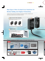
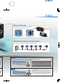
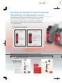
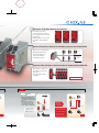
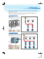
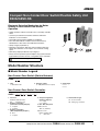
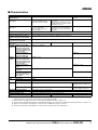
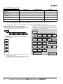
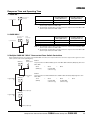
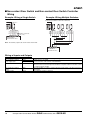
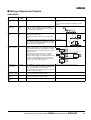
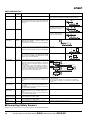
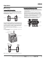
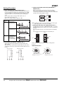
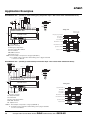
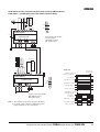
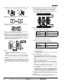
NEW
Compact Non-Contact Door Switch/
Flexible Safety Unit
D40A/G9SX-NS
Stable Operation Increases Line Efficiency
New Type of Non-Contact Door Switches for
Worker Safety and Higher Productivity
These new Non-Contact Door Switches provide more stability in detection than
previously possible with non-contact door switches.
● Easy-to-see
2-Color Indicators
Switch status is easy to see at a glance with
these red/yellow LED indicators.
Yellow:
Closed door
detected.
Red:
Open door
detected.
● Small
Not lit:
Power OFF
or failure
Actuator
An actuator that is smaller than the switch saves
space, even inside the door.
Even when mounted with an L-bracket, the
actuator's height will not hinder installation or
operation.
Compact
Switch
Actuator
Solves Conventional Switch Issues to Provide Stable Detection
Issue 1
The Switch does not accurately detect the door when it is closed slowly, resulting in an error.
Conventional switch
An error can occur
if the door is closed
slowly with
conventional
switches.
Door
closed
slowly.
Solution 1
The D40A does not use reed switches and
provides stable detection with electronic switches.
Conventional Switches
Slow
Magnet
Reed switch contacts
Slow
Magnet
Reed switch contacts
Error
If the switching timing of
reed switch contacts 1
and 2 varies too much,
the Controller detects an
error and turns OFF the
output to maintain safety.
Note: The figure is intended
only as an illustration.
Is
Stable Detection
with the D40A's
New System
Detects slow lateral operation.
Detects slow rotating operation.
So
rror.
eration.
● Mount
from Either Side
Mount from whichever side provides the easiest wiring
path to enable mounting to all types of doors.
Swinging doors
● Connect
Mount from
Either Side
Sliding doors
Up to 30 Switches to a Single Controller
Reduce costs by connecting up to 30 Switches to a single Controller.
Up to 30 Switches
Issue 2
It is nearly impossible to tell which door is open in a multi-door application.
If an error occurs...
The system cannot be started because the Controller has turned
OFF the output even though all doors appear to be closed.
It's impossible to tell if there is a door open or if an error has occurred.
All doors must be opened and closed before operation can be
started.
Solution 2
With the D40A...
The auxiliary outputs can be used to easily indicate which door is
open.
And with two-color indicators, mounting adjustments are also easy.
The D40A is the first Non-contact Door Switch to combine 2-color
indicators, auxiliary outputs, and 30-switch connection capacity,
allowing you to create a better safety environment.
Two Types of Controller to Solve Productivity,
Expandability, and Maintenance Issues
The G9SX-NS and G9SX-NSA are designed specifically for use with the
D40A, and with the G9SX-NSA you can also connect mechanical safety
door switches. Among other features, these Controllers support logical
AND connections that enable partial stops. These Controllers make the
most of D40A Switches.
● Two
Different Controllers
G9SX-NS
G9SX-NSA
@Logical AND
connection input
@Logical AND
connection input
@D40A input
@D40A plus mechanical
safety door switch input,
channel 1 or 2
@Two instantaneous
safety outputs
@Two instantaneous safety
outputs
@Two OFF-delay safety
outputs
@Logical AND
connection output
@Logical AND
connection output
Reduce Costs with these New-Concept Controllers
Issue 1
Two Controllers are required for emergency stop switches and
non-contact door switches.
Application
●One hazard.
●The system must be stopped
when either a door is opened
or an emergency stop switch
is pressed.
D40B
D40B-J1
Emergency
stop switch
(See note.)
The G9SA must be
added to connect the
G9SA
emergency stop
switch.
D40A
Emergency
stop switch
(See note.)
Two
Controllers
The D40A
Simplifies the
Configuration
With only one G9SXNSA222-T03@
Controller, both a Noncontact Door Switch
and an emergency
stop switch can be
connected.
G9SX-NSA
One
Controller
● Indicators That
Make Maintenance Easier
The indicators show the
location and cause of wiring
errors and any other errors that
are detected.
Auxiliary outputs for errors also
contribute to reducing down
time.
Input error
Logical AND
connection error
Output error
● Mechanical Safety Door Switches Can Also Be Connected with the G9SX-NSA
Inputs can be accepted from
both D40A Switches and
mechanical switches to
reduce the number of
Controllers and costs.
D40A
Safety Door
Switches
● Expansion Units to Easily Increase the Number of Outputs with the G9SX-NSA
The number of outputs can
be easily increased using
connectors.
Up to 25 outputs can be
configured.
Up to 25 Outputs
G9SX-EX Expansion Unit
Issue 2
Another Controller has to be added to use an OFF-delay timer.
Application
D40A
●Two hazards.
●The power supply must be
turned OFF immediately when
the emergency stop switch is
pressed.
●When a door is opened, a
stop signal is sent to only
servomotor B and then the
power supply is turned OFF.
D40B-J1
Emergency
stop switch
(See note.)
Wiring
D40A
Emergency
stop switch
(See note.)
D40B
The D40A
Simplifies the
Configuration
G9SX-BC
The G9SA must be
A Controller can be
G9SA
added to use an
G9SA-321-T@
OFF-delay output
OFF-delay timer.
eliminated because
the G9SX-NSA222T03@ provides an
One
Controller
G9SX-NSA
Logical AND
connection
Three
A
B
Controllers
OFF-delay output.
A
B
Two
Controllers
Note: Always use a manual reset when using an emergency stop.
Configuration Example for Logical AND Connections with the G9SX
Logical AND Connections
OMRON's unique logical AND connections enable easily constructing safety circuits that were troublesome with
previous Controllers. The new Non-contact Door Switch Controllers embody the concepts for the G9SX Series, so you
can also use the previous G9SX-series Controllers in the same system.
Small Assembly System
●Both robots will stop when the emergency stop
switch is pressed.
●Robot A will stop when robot door A is opened.
●Robot B will stop when robot door B is opened.
(1) Emergency stop
switch
(2) Robot door A
(3) Robot door B
D40A
D40A
G9SX-BC
Logical AND connections
Robot door B
Robot door A
G9SX-NS
G9SX-NS
Operation Examples
(1) Emergency stop
switch pressed.
(2) Robot door A
opened.
Stop Stop
Robot A
(3) Robot door B
opened.
Stop Stop
Stop
Robot B
Robot A
Robot B
Robot A
Robot A
Robot B
Robot B
Semiconductor Inspection System
●The entire system will stop if the emergency stop switch is pressed.
●Only segment A will stop if door A (with door switch) is opened.
●Only segment B will stop if door B (with door switch) is opened.
●Only segment C will stop if the door with the D40A is opened.
(2) Door A (with door switch)
(1) Emergency stop
switch
(3) Door B (with door switch)
(2) Door A
(3) Door B
(4) Door with D40A
(4) Door with
the D40A
Safety Door Switch
G9SX-BC
Safety Door Switch
D40A
G9SX-AD
G9SX-NS
Logical AND
connections
(1) Emergency stop
switch
Segment A
Segment B
Segment C
Operation Examples
(1) Emergency stop switch
pressed.
Stop Stop Stop
Segment A
Segment B
Segment C
(3) Door B opened.
(2) Door A opened.
G9SX-AD
Stop
Segment A
Segment B
Segment C
(4) Door with D40A opened.
Stop Stop Stop
Stop Stop Stop
Segment A
Segment A
Segment B
Segment C
Segment B
Segment A
Segment B
Segment C
Segment C
Note: Refer to the G9SX datasheet (Cat. No. J150) and to the 2006 Safety Components Series Group Catalog (Cat. No. Y106) for details on logical AND connections and the G9SX-series Controllers.
Compact Non-Contact Door Switch/Flexible Safety Unit
D40A/G9SX-NS
Electronic Detection Mechanism for Better
Stability in Non-contact Door Switch
Operation
• Stable operation reduces Controller errors caused by unstable
doors.
• Connect up to 30 Non-contact Door Switches with LED
indicators to one Controller.
• Reversible switch provides flexibility in installation.
• Two-color LED indicator enables easier maintenance by
identification of door status and cable disconnections.
• Safety category 3 (EN 954-1).
• Both Non-contact Door Switches and conventional Key-type
Safety-door Switches can be input to one Controller, saving
space.
• OFF-delay output provided for stop category 1.
• Easily construct partial stop and complete stop systems with the
logical AND connection function, using G9SX as the Controller.
Refer to “Precautions” on page 28.
Model Number Structure
■ Model Number Legend
Non-Contact Door Switch (Switch/Actuator)
D40A - @@@
1 2 3
1. Type
1: Standard model
2. Auxiliary outputs
C: 1NO (PNP transistor output)
3. Cable length
2: 2 m
5: 5 m
Non-Contact Door Switch Controller
G9SX - @@@@@@ - @@@ - @@
1
2 3 4
5
1. Functions
NS/NSA: D40A Controller
EX:
Expansion Unit
2. Output Configuration
(Instantaneous Safety Outputs)
2: 2 outputs
4: 4 outputs
3. Output Configuration
(OFF-delayed Safety Outputs)
0: None
2: 2 outputs
6
4. Output Configuration
(Auxiliary Outputs)
1: 1 output
2: 2 outputs
5. Max. OFF-delay Time
6. Terminal Block Type
RT: Screw terminals
RC: Spring-cage terminals
D40A Controller
T03: 3 s (Variable)
Expansion Unit
Blank: No OFF delay
T:
OFF delay
Compact Non-Contact Door Switch
D40A/Flexible Safety Unit G9SX-NS
7
Ordering Information
Non-Contact Door Switches (Switch/Actuator)
Classification
Appearance
Auxiliary outputs
Standard models
Semiconductor outputs
(See note 2.)
Cable length
Mode
2m
D40A-1C2
5m
D40A-1C5
Note: 1. Must be used in combination with a G9SX-NS@ Non-contact Door Switch Controller.
2. PNP open-collector semiconductor output.
Non-Contact Door Switch Controllers (Controllers for D40A)
Max. OFF
Logical
Logical
Auxiliary
outputs AND con- AND con- delay time
nection (See note 4.)
OFF-delayed (See note nection
output
input
3.)
(See note 2.)
Safety outputs
(See note.1)
Instantaneous
1
0
2
2
(Semicon(Semiconductors)
ductors)
2
(Semiconductors)
Note: 1.
2.
3.
4.
1
---
Rated
voltage
24 VDC
Terminal block type
Screw terminals
Model
G9SX-NS202-RT
Spring-cage terminals G9SX-NS202-RC
3.0 s
Screw terminals
G9SX-NSA222-T03-RT
Spring-cage terminals G9SX-NSA222-T03-RC
P channel MOS FET transistor output
The OFF-delayed output becomes an instantaneous output by setting the OFF-delay time to 0 s.
PNP transistor output
The OFF-delay time can be set in 16 steps as follows:
0/0.2/0.3/0.4/0.5/0.6/0.7/0.8/0.9/1.0/1.2/1.4/1.8/2.0/2.5/3.0 s
Expansion Units
Safety outputs
Instantaneous
4PST-NO
---
OFF-delayed
--4PST-NO
Auxiliary
outputs
OFF-delay time Rated voltage Terminal block type
--1
(Semiconductor)
(See note 1.)
(See note 2.)
24 VDC
Screw terminals
Model
G9SX-EX401-RT
Spring-cage terminals G9SX-EX401-RC
Screw terminals
G9SX-EX041-T-RT
Spring-cage terminals G9SX-EX041-T-RC
Note: 1. PNP transistor output
2. The OFF-delay time is synchronized to the OFF-delay time setting in the connected Controller (G9SX-NSA222-T03-@).
8
Compact Non-Contact Door Switch D40A/Flexible Safety Unit
G9SX-NS
Specifications
■ Ratings/Characteristics of Non-contact Door Switches
Item
Operating
characteristics
(See note 1.)
Model
D40A-1C@
Operating distance OFF→ON
5 mm min.
Operating distance ON→OFF
15 mm max.
Differential travel (max.)
20% of operating distance
Influence of temperature (max.)
±20% of operating distance at 23°C, within temperature range of −10 to 55°C
Ambient operating temperature
−10 to 55°C (no icing or condensation)
Ambient operating humidity
25% to 85%
Insulation resistance (between charged parts and case) 50 MΩ max. (at 500 VDC)
Dielectric strength (between charged parts and case)
1,000 VAC for 1 min
Vibration resistance
10 to 55 to 10 Hz (single amplitude: 0.75 mm, double amplitude: 1.5 mm)
Shock resistance
300 m/s2 min.
Degree of protection
IP67
Material
PBT resin
Mounting method
M4 screws
Terminal screw tightening torque
1 N·m
Power consumption
0.6 W max.
Auxiliary outputs (See note 2.)
24 VDC, 10 mA (PNP open-collector outputs)
LED indicators
Actuator not detected (red); actuator detected (yellow)
Connection cables
2 m, 5 m
Number of connectable switches (See note 3.)
30 max. (wiring length: 100 m max.)
Weight
Switch: approx. 145 g, actuator: approx. 20 g (D40A-1C2)
Note: 1. This is the distance where the switch operates from OFF to ON when approaching and the distance where the switch operates from ON
to OFF when separating when the switch and actuator target marks are on the same axis, and the sensing surfaces coincide.
2. Turns ON when the actuator is approaching.
3. For details, refer to item 5 on page 29.
Compact Non-Contact Door Switch
D40A/Flexible Safety Unit G9SX-NS
9
■ Ratings of Non-contact Door Switch Controllers
Power input
Item
Model
Rated supply voltage
G9SX-NS202-@
G9SX-NSA222-T03-@
G9SX-EX-@
24 V DC
Operating voltage range
−15% to 10% of rated supply voltage
Rated power consumption (See note.)
3 W max.
4 W max.
2 W max.
Note: Power consumption of loads not included.
Inputs
Item
Model
G9SX-NS202-@/G9SX-NSA222-T03-@
Operating voltage: 20.4 VDC to 26.4 VDC, internal impedance: approx. 2.8 kΩ
Safety input (See note.)
Feedback/reset input
Note: Only applies to the G9SX-NSA222-T03-@. Refers to input other than that from the Non-contact Door Switch.
Outputs
Item
Model
G9SX-NS202-@/G9SX-NSA222-T03-@
Instantaneous safety output (See note 1.) P channel MOS FET transistor output
OFF-delayed safety output (See note 1.) Load current: 0.8 A DC max. (See note 2.)
Auxiliary output
PNP transistor output
Load current: 100 mA max.
Note: 1. While safety outputs are in the ON state, the following signal sequence is output continuously for diagnosis.
When using the safety outputs as input signals to control devices (i.e. Programmable Controllers), consider the OFF pulse shown below.
Approx.100 ms
ON
OFF
360 µs max.
2. The following derating is required when Units are mounted side-by-side.
G9SX-NS202-@/G9SX-NSA222-T03-@: 0.4 A max. load current
Expansion Unit
Item
Model
G9SX-EX-@
Rated load
250 VAC, 3 A/30 VDC, 3 A (resistive load)
Rated carry current
3A
Maximum switching voltage 250 VAC, 125 VDC
10
Compact Non-Contact Door Switch D40A/Flexible Safety Unit
G9SX-NS
■ Characteristics
Item
Model
G9SX-NS202-@
G9SX-NSA222-T03-@
G9SX-EX-@
Over-voltage category
(IEC/EN 60664-1)
II
II (Relay outputs 13 to 43 and 14 to
44: III)
Operating time (OFF to ON state)
(See note 1.)
100 ms max. (Logical AND
connection input ON and Noncontact Door Switch input ON)
30 ms max. (See note 4.)
50 ms max. (Safety input: ON)
(See note 2.)
100 ms max. (Logical AND connection
input ON and Non-contact Door Switch
input ON) (See note 3.)
Response time (ON to OFF state)
(See note 1.)
15 ms max. (Logical AND
connection input: OFF)
20 ms max. (Non-contact Door
Switch input OFF)
10 ms max. (See note 4.)
15 ms max. (Safety input OFF and
logical AND connection input OFF)
20 ms max. (Non-contact Door Switch
input: OFF)
ON-state residual voltage
3.0 V max. (safety output, auxiliary output)
OFF-state leakage current
0.1 mA max. (safety output, auxiliary output)
Maximum wiring length of safety input, logical AND connection input,
and Non-contact Door Switch input
100 m max. (External connection impedance: 100 Ω max. and 10 nF max.)
Reset input time
(Reset button pressing time)
100 ms min.
Accuracy of OFF-delay time
(See note 5.)
---
Within ±5% of the set value
20 MΩ min. (at 100 VDC)
Insulation Between logical AND
resistance connection terminals,
and power supply input
terminals and other input
and output terminals connected together
Dielectric
strength
Within ±5% of the set value
---
Between all terminals
connected
together and DIN rail
100 MΩ min.
(at 500 VDC)
500 VAC for 1 min.
Between logical AND
connection terminals,
and power supply input
terminals and other input
and output terminals connected together
---
Between all terminals
connected together and
DIN rail
1,200 VAC for 1 min
Between different poles
of outputs
---
Between relay outputs
connected together and
other terminals connected together
2,200 VAC for 1 min
Vibration resistance
10 to 55 to 10 Hz, 0.375-mm single amplitude (0.75-mm double amplitude)
Shock
Destruction
resistance
Malfunction
300 m/s2
Durability
Electrical
---
100,000 cycles min. rated load,
switching frequency: 1,800 cycles/
hour)
Mechanical
---
5,000,000 cycles min. (switching
frequency: 7,200 cycles/hour)
100 m/s2
Ambient operating temperature
−10 to 55°C (no icing or condensation)
Ambient operating humidity
25% to 85%
Terminal tightening torque
0.5 N·m (For the G9SX-NS@-RT (with screw terminals) only)
Weight
Approx. 125 g
Approx. 200 g
Approx. 165 g
Note: 1. When two or more Units are connected by logical AND, the operating time and response time are the sum total of the operating times
and response times, respectively, of all the Units connected by logical AND.
2. Represents the operating time when the safety input turns ON with all other conditions set.
3. Represents the operating time when the logical AND input and the Non-contact Door Switch input turn ON with all other conditions set.
4. This does not include the operating time or response time of G9SX-NS@ that are connected.
5. This does not include the operating time or response time of internal relays in the G9SX-EX-@.
Compact Non-Contact Door Switch
D40A/Flexible Safety Unit G9SX-NS
11
Logical AND Connection
Item
Model
Number of Units connected per logical
AND output
G9SX-NS202-@
G9SX-NSA222-T03-@
4 Units max.
G9SX-EX-@
---
Total number of Units connected by logical 20 Units max.
AND (See note 2.)
---
Number of Units connected in series by
logical AND
5 Units max.
---
Max. number of Expansion Units
connected (See note 3.)
---
5 Units max.
Maximum cable length for logical AND
input
100 m max.
---
Note: 1. See Logical AND Connection Combinations below for details.
2. The number of G9SX-EX401-@ Expansion Units or G9SX-EX041-T-@ Expansion Units (OFF-delayed Model) not included.
3. G9SX-EX401-@ Expansion Units and G9SX-EX041-T-@ Expansion Units (OFF-delayed Model) can be mixed.
Logical AND Connection Combinations
1. One logical AND connection output from a G9SX-NS@ Controller
can be logical AND connected to up to four Controllers.
3. The largest possible system configuration contains a total of 20
G9SX-NS@ Controllers, G9SX-AD@ Advanced Units, and G9SXBC Basic Units. In this configuration, each Controller or Advanced
Unit can have up to five Expansion Units.
G9SX-NS@
G9SX-@
G9SX-NS@
G9SX-NS@
G9SX-NS@
G9SX-NS@
G9SX-AD@
or
G9SX-NS@
G9SX-AD@
or
G9SX-NS@
G9SX-AD@
or
G9SX-NS@
G9SX-AD@
or
G9SX-NS@
G9SX-AD@
or
G9SX-NS@
G9SX-AD@
or
G9SX-NS@
G9SX-AD@
or
G9SX-NS@
G9SX-AD@
or
G9SX-NS@
G9SX-AD@
or
G9SX-NS@
G9SX-AD@
or
G9SX-NS@
G9SX-AD@
or
G9SX-NS@
G9SX-AD@
or
G9SX-NS@
G9SX-AD@
or
G9SX-NS@
G9SX-AD@
or
G9SX-NS@
G9SX-AD@
or
G9SX-NS@
G9SX-AD@
or
G9SX-NS@
2. Any G9SX-NS@ Controller that receives a logical AND
connection input can be logically connected to other Controllers
on up to five layers.
G9SX-NS@
G9SX-NS@
G9SX-NS@
G9SX-NS@
G9SX-NS@
Number of Units connected
in series by logical AND: 5
Units max.
Note: The G9SX-NS@ in the above diagram can be replaced by the
G9SX-AD@ Advanced Unit.
For details on G9SX-AD@ Advanced Units, refer to the G9SXseries Flexible Safety Unit catalog. (Cat. No. J150).
12
Compact Non-Contact Door Switch D40A/Flexible Safety Unit
G9SX-NS
G9SX-AD@
or
G9SX-NS@
Number of Units connected
per logical AND output: 4
Units max.
G9SX-AD@
or
G9SX-NS@
G9SX-AD@
or
G9SX-NS@
Total number of Units
connected by logical AND:
20 Units max.
Response Time and Operating Time
1. G9SX-NS@
Max. response time
(excluding Expansion
Units) (See note 1.)
Non-contact Door
Switch input
Logical AND input
Max. operating time
(excluding Expansion
Units) (See note 2.)
Non-contact Door Switch input 20 ms
100 ms
Logical AND input
100 ms
20 ms
Note: 1. The maximum response time is the time it takes the output to switch from ON to OFF
after the input switches from ON to OFF.
2. The maximum operating time is the time it takes the output to switch from OFF to ON
after the input switches from OFF to ON.
2. G9SX-NSA@
Non-contact Door
Switch input
Max. response time
(excluding Expansion
Units) (See note 1.)
D4NS
Safety input
Logical AND input
Max. operating time
(excluding Expansion
Units) (See note 2.)
Non-contact Door Switch input
20 ms
100 ms
Safety input
15 ms
50 ms
Logical AND input
20 ms
100 ms
Note: 1. The maximum response time is the time it takes the output to switch from ON to OFF
after the input switches from ON to OFF.
2. The maximum operating time is the time it takes the output to switch from OFF to ON
after the input switches from OFF to ON.
3. Multiple G9SX-NS@/NSA@ Non-contact Door Switch Controllers
When multiple Controllers are logically connected with AND connections, the response time is the sum of the response times given in 1 and 2
above. (It is the same for the operating time.)
D4NS
Case 1
D40A (1)
Safety input
Response Time from When D40A (1) Turns from ON to OFF until Safety Output (2) Turns from
ON to OFF
(
20 ms
(D40A (1))
+
20 ms
=
(Logical AND
connection (1))
40 ms
Case 2
Safety output
(1)
Logical AND
(1)
D40A (2)
Response Time from When D4NS Turns from ON to OFF until Safety Output (3) Turns from
ON to OFF
15 ms
(D4NS)
+
20 ms
+
(Logical AND
connection (1))
20 ms
=
(Logical AND
connection (2))
55 ms
Safety output (2)
D40A (3)
Logical AND
(2)
Safety output (3)
Compact Non-Contact Door Switch
D40A/Flexible Safety Unit G9SX-NS
13
Engineering Data
Operating distance Y (mm)
Operating distance Y (mm)
Detection Ranges (Typical Characteristics Data)
16
14
OFF
12
10
14
12
OFF
10
8
8
6
ON
6
ON
4
4
2
2
0
−6
−4
−2
0
2
4
Distance from the target mark on the switch X (mm)
X
6
0
−15
−10
−5
0
Sensing surface
Sensing surface
Z
Y
Target marks
Y
Target marks
Note: 1. The operating distance is the distance between the switch and actuator sensing surfaces.
2. Data in the diagram is typical data at an ambient temperature of 23°C. Actual operating values may vary.
The operating distance may be affected by ambient metal, magnet catches, and temperature.
14
5
10
15
Distance from the target mark on the switch Z (mm)
Compact Non-Contact Door Switch D40A/Flexible Safety Unit
G9SX-NS
Connections
■ Internal Connection
G9SX-NS202-@ (Non-contact Door Switch Controller)
A1
D1 D2 D3 D4 T31 T32 T33
T41 T42
A1
(See
note 2.)
Logical AND
input
S14 S24
L1
X1
T11 T12 T21 T22 T31 T32 T33 Y1 D1 D2 D3 D4 T41 T42
(See
note
2.)
Power Non-contact Door Reset/Feedback
supply
Input
Switch control
circuit
Auxiliary
(See
Safety output control
output control
note 1.)
A2
G9SX-NSA222-T03-@
(Non-contact Door Switch Controller)
Power
supply
circuit
(See
note 1.)
Safety
input 1
Safety
input 2
fault
Reset/Feedback Cross
detection Non-contact Door
Input
Switch control
input
Safety output control
Auxiliary
output control
Logical
AND input
Expansion Unit
output control
X2
A2
(See note 3.)
S14 S24 S44 S54 L1
X1
X2
(See note 3.)
Note: 1. Internal power supply circuit is not isolated.
2. Logical AND input is isolated.
3. Outputs S14 to S24 are internally redundant.
G9SX-EX401-@/G9SX-EX041-T-@
(Expansion Unit/Expansion Unit OFF-delayed Model)
A1
Note: 1. Internal power supply circuit is not isolated.
2. Logical AND input is isolated.
3. Outputs S14 to S54 are internally redundant.
13 23 33 43
(See note 1.)
Exp.
sig.
IN
Safety
output
Power control
supply
Auxiliary
circuit
output
control
A2
X2
(See note 2.)
K1
Exp.
sig.
OUT
K2
14 24 34 44
Note: 1. Internal power supply circuit is not isolated.
2. Relay outputs are isolated.
■ Internal Circuit Diagram
D40A-1C@
Brown
Internal circuit
Blue
White
Black
Yellow
Compact Non-Contact Door Switch
D40A/Flexible Safety Unit G9SX-NS
15
Dimensions
Note: All units are in millimeters unless otherwise indicated.
Non-contact Door Switch (Switch/Actuator)
D40A-1C2
D40A-1C5
48
7.2 dia.
48
7.2 dia.
12
38
7.2 dia.
Sensing surface
6
13
17
9.5
Sensing surface
7.2 dia.
38
Indicator
(2)
Two, 4.2 dia.
(2)
20
25
Two, 4.2 dia.
Vinyl-insulated round cord, dia. 4,
5-conductor (conductor cross-sectional area:
0.2 mm2,Insulator diameter: 1.0 mm)
Standard length: 2 m/5 m
13
(Actuator)
(Switch)
Non-contact Door Switch Controller
(6) (See note 3.)
G9SX-NS202-@
Terminal arrangement
T31 T32 T33 D3
D1 D2 X1 A1
T31 T32 T33 D3
D1 D2 X1 A1
G9SX-NS202
24VDC
PWR
EI
PWR
FB
AND
NS
FB
AND
100 max.
NS
ERR
EI
ERR
No.
T41 T42 X2
S14 S24 L1
A2
D4
T41 T42 X2 A2
S14 S24 L1 D4
23 max.
115 max.
(6) (See note 3.)
(22.5)(See note 1.)
Note: 1. Typical dimension
2. Above outline drawing is for models with spring-cage terminals (-RC).
3. For models with spring-cage terminals (-RC) only.
Non-contact Door Switch Controller
Terminal arrangement
(6) (See note 3.)
G9SX-NSA222-T03-@
T31 T32 T33 D1 D2 D3
T11 T12 Y1 X1 X2 A1
T31 T32 T33 D1
T11 T12 Y1 X1
D2
X2
D3
A1
G9SX-NSA222-T30
24VDC
PWR
0.7
0.6
0.5
0.4
0.3
0.2
FB
T1
T2
AND
NS
EI
ED
0.8 0.91.0
1.2
1.4
1.8
2.0
2.5
0 3.0
OFF-DELAY
PWR
FB
T1
T2
AND
NS
EI
ED
100 max.
ERR
ERR
No.
T21 T22
T41 T42
S14 S24 S44 S54 L1
A2
D4
T21 T22
T41 T42 A2
S14 S24 S44 S54 L1 D4
35.5 max.
(10)
(35) (See note 1.)
115 max.
(6) (See note 3.)
Note: 1. Typical dimension
2. Above outline drawing is for models with spring-cage terminals (-RC).
3. For models with spring-cage terminals (-RC) only.
16
Compact Non-Contact Door Switch D40A/Flexible Safety Unit
G9SX-NS
Expansion Unit
G9SX-EX401-@
Expansion Unit (OFF-delayed Model)
G9SX-EX041-T-@
Terminal arrangement
G9SX-EX401-@
(Expansion Unit)
G9SX-EX041-T-@
(Expansion Unit
with OFF Delay)
13 23 33 43
13 23 33 43
PWR
PWR
EI
ED
ERR
ERR
(6) (See note 3.)
100 max.
23 max.
115 max.
(22.5) (See note 1.)
A1 X2 A2
A1 X2 A2
14 24 34 44
14 24 34 44
(6) (See note 3.)
Note: 1. Typical dimension
2. Above outline drawing is for models with spring-cage terminals (-RC).
3. For models with spring-cage terminals (-RC) only.
Compact Non-Contact Door Switch
D40A/Flexible Safety Unit G9SX-NS
17
■ Non-contact Door Switch and Non-contact Door Switch Controller
Wiring
Example: Wiring a Single Switch
Example: Wiring Multiple Switches
Connect Up to 30 Non-contact Door Switches
D1 D2 D3 D4
Blue
Brown
Black
White
Blue
Brown
Black
White
Blue
Brown
Auxiliary output load
(See note.)
Black
White
Blue
Yellow
Black
Brown
White
D40A-1C@
A2
G9SX-NS202-@
G9SX-NSA222-T03-@
Note: The auxiliary output load current must be 10 mA max.
D1 D2 D3 D4
G9SX-NS202-@
G9SX-NSA222-T03-@
Wiring of Inputs and Outputs
Signal name
Non-contact Door Switch
power supply input
Wire color
Brown
Blue
Description of operation
Supplies power to the D40A.
Connect to the D3 or D4 terminal of the G9SX-NS@.
Non-contact Door Switch input White
Inputs signals from the G9SX-NS@.
The Non-contact Door Switch input must be ON as a required condition for the Non-contact
Door Switch output to be ON.
Non-contact Door Switch
output
Black
Turns ON and OFF according to actuator detection and the status of the Non-contact Door
Switch input.
Auxiliary output
Yellow
Turns ON when actuator is detected.
18
Compact Non-Contact Door Switch D40A/Flexible Safety Unit
G9SX-NS
■ Wiring of Inputs and Outputs
G9SX-NS202-@
Signal name
Power supply
input
Terminal
name
A1, A2
Non-contact Door D1, D2,
Switch input
D3, D4
Description of operation
Wiring
Connect the power source to the A1 and A2 terminals. Connect the power supply plus (24 VDC) to the A1
terminal.
Connect the power supply minus (GND) to the A2
terminal.
All Non-contact Door Switch inputs connected to the
G9SX-NS@ must be ON as a required condition for
the safety outputs to be ON. Otherwise the safety outputs cannot be in the ON state.
White
D1
Feedback/reset
input
T31, T32,
T33
T41, T42
D2
To set the safety outputs in the ON state, the ON state Auto reset
signal must be input to T33.
Otherwise the safety outputs cannot be in the ON
state.
A logical AND connection means that one unit (Unit A)
outputs a safety signal “a” to a subsequent unit (Unit
B) and Unit B calculates the logical AND (i.e., outputs
the AND) of the signal “a” and safety signal “b”, which
is input to Unit B.
Thereby the logic of the safety output of Unit B is
(AND). (An AND of inputs “a” and “b” is output.)
To set the safety outputs of the subsequent Unit in the
ON state, its logical AND connection preset switch
must be set to AND (enable) and the high signal must
be input to T41 of the subsequent unit.
Blue
D3
D4
Feedback loop
KM
+24 V
T31
To set the safety outputs in the ON state, the signal in- Manual reset
put to T32 must change from the OFF state to the ON
state, and then to the OFF state. Otherwise the safety
outputs cannot be in the ON state.
Logical AND
connection input
Black Brown
T32
T33
Feedback loop
Reset
Switch
KM +24 V
T31
T32
T33
Input a
Unit A
G9SX-NS/NSA
Output (a) L1 A2
Unit B
Logical AND connection sig.
(1st layer)
Input b
T41 T42
G9SX-NS/NSA
Output (a&b) L1 A2
Next unit (4 unit max.)
T41 T42
G9SX-NS/NSA
Logical AND connection sig.
(2nd layer)
Next unit (4 unit max.)
T41 T42
G9SX-NS/NSA
L1 A2
Next unit (5 layers max.)
Instantaneous
safety output
S14, S24
Turns ON/OFF according to the state of the safety in- Keep these outputs open when not used.
puts, Non-contact Door Switch inputs, feedback/reset
inputs, and logical AND connection inputs.
During OFF-delay state, the Instantaneous safety outputs are not able to turn ON.
Logical AND
L1
connection output
Outputs a signal of the same logic and at the same
time as the instantaneous safety outputs.
Keep these outputs open when not used.
Auxiliary monitor
output
X1
Outputs a signal of the same logic and at the same
time as the instantaneous safety outputs
Keep these outputs open when not used.
Auxiliary error
output
X2
Outputs when the error indicator is lit or flashing.
Keep these outputs open when not used.
Compact Non-Contact Door Switch
D40A/Flexible Safety Unit G9SX-NS
19
G9SX-NSA222-T03-@
Signal name
Terminal
name
Description of operation
Wiring
Power supply input A1, A2
Connect the power source to the A1 and A2 terminals. Connect the power supply plus (24 VDC) to the A1 terminal.
Connect the power supply minus (GND) to the A2 terminal.
Safety input 1
To set the safety outputs in the ON state, the high state Corresponds to Safety Categosignals must be input to both safety input 1 and safety ry 2
input 2. Otherwise the safety outputs cannot be in the
ON state.
T11, T12
+24 V
+24 V
T11 T12 T21 T22
Corresponds to Safety Category 3 (without short-circuit monitoring between systems)
Safety input 2
+24 V
Y1
+24 V
+24 V
T21, T22
T11 T12 T21 T22
Y1
T11 T12 T21 T22
Y1
Corresponds to Safety Category 3 (Cross fault detecting
mode (for safety inputs))
NC
Non-contact Door
Switch input
D1, D2,
D3, D4
All Non-contact Door Switch inputs connected to the
G9SX-NS must be ON as a required condition for the
safety outputs to be ON.
Otherwise the safety outputs cannot be in the ON state.
White
D1
Feedback/reset
input
Black Brown
D2
Blue
D3
D4
T31, T32, To set the safety outputs in the ON state, the ON state Auto reset
T33
signal must be input to T33.
Otherwise the safety outputs cannot be in the ON state.
Feedback loop
+24 V
T31
To set the safety outputs in the ON state, the signal in- Manual reset
put to T32 must change from the OFF state to the ON
state, and then to the OFF state. Otherwise the safety
outputs cannot be in the ON state.
T41, T42, A logical AND connection means that one unit (Unit A)
T51, T52 outputs a safety signal “a” to a subsequent unit (Unit B)
and Unit B calculates the logical AND (i.e., outputs the
AND) of the signal “a” and safety signal “b”, which is input to Unit B.
Thereby the logic of the safety output “b” is output.)
To set the safety outputs of the subsequent Unit in the
ON state, its logical AND connection preset switch
must be set to AND (enable) and the high signal must
be input to T41 of the subsequent unit.
T33
Feedback loop
Reset
Switch
KM +24 V
T31
Logical AND
connection input
T32
KM
T32
T33
Input a
Unit A
G9SX-NS/NSA
Output (a) L1 A2
Unit B
Logical AND connection sig.
(1st layer)
Input b
T41 T42
G9SX-NS/NSA
Output (a&b) L1 A2
Next unit (4 unit max.)
T41 T42
G9SX-NS/NSA
Logical AND connection sig.
(2nd layer)
Next unit (4 unit max.)
T41 T42
G9SX-NS/NSA
L1 A2
Next unit (5 layers max.)
Cross fault
detection input
Y1
Selects the mode for the failure detecting (cross fault
detecting) function for the safety inputs of G9SX corresponding to the connection of the cross fault detection
input.
Keep Y1 open when using T11, T21. (Cross fault detecting mode
(for safety inputs))
Connect Y1 to 24 VDC when not using T11, T21. (Wiring
corresponding to category 2 or 3, or when connecting safety
sensors)
Instantaneous
safety output
S14, S24
Turns ON/OFF according to the state of the safety in- Keep these outputs open when not used.
puts, feedback/reset inputs, and logical AND connection inputs.
During OFF-delay state, the Instantaneous safety outputs are not able to turn ON.
OFF-delayed
safety output
S44, S54
OFF-delayed safety outputs.
The OFF-delay time is set by the OFF-delay preset
switch.
When the delay time is set to zero, these outputs can
be used as non-delay outputs.
Logical AND
connection output
L1
Outputs a signal of the same logic and at the same time Keep these outputs open when not used.
as the instantaneous safety outputs.
Auxiliary monitor
output
X1
Outputs a signal of the same logic and at the same time Keep these outputs open when not used.
as the instantaneous safety outputs.
Auxiliary error
output
X2
Outputs when the error indicator is lit or flashing.
Keep these outputs open when not used.
Keep these outputs open when not used.
■ Connecting Safety Sensors
Safety sensors cannot be connected to safety inputs for the G9SX-NSA222-T03-@.
20
Compact Non-Contact Door Switch D40A/Flexible Safety Unit
G9SX-NS
Operation
■ Functions
Connecting Expansion Units
Logical AND Connection
A logical AND connection means that the G9SX outputs a safety
signal “a” to another G9SX, and that G9SX creates the logical AND
of safety signal “a” and safety signal “b.” The safety output of the
G9SX-NSA222-T03-@ with the logical AND connection shown in the
following diagram is “a” AND “b.”
a
b
G9SX-NS202-@
G9SX-NSA222-T03-@
a
• The G9SX-EX and G9SX-EX-T Expansion Units can be connected
to a G9SX-NSA222-T3-@ Non-contact Door Switch Controller to
increase the number of safety outputs. (They cannot be connected
to a G9SX-NS202-@.)
• A maximum of five Expansion Units can be connected to one
G9SX-NSA222-T03-@. This may be a combination of G9SX-EX
instantaneous models and G9SX-EX-T OFF-delayed models.
• Remove the terminating connector from the receptacle on G9SXNSA222-T03-@ and insert the Expansion Unit cable connector into
the receptacle. Insert the terminating connector into the receptacle
on the Expansion Unit at the very end (rightmost).
• When Expansion Units are connected to a Controller, make sure
that power is supplied to every Expansion Unit. (Refer to the
following diagram for actual Expansion Unit connection.)
a (AND) b
Terminating
connector
This is illustrated using the application in the following diagram as an
example. The equipment here has two hazards identified as Robot 1
and Robot 2, and it is equipped with Non-contact Door Switches and
an emergency stop button as safety measures. If the door to Robot 2
is opened, only Robot 2 is stopped (i.e., a partial stop). If the door to
Robot 1 is opened or the emergency stop button is pressed, both
Robot 1 and Robot 2 stop (i.e., a complete stop).
G9SX-NSA222-T03-@
Expansion Unit
The actual situation using a G9SX for this application is shown in this
example.
Note: The logical AND setting on the G9SX-NS202-@ must be set to
AND (enabled).
Non-contact Door Switch 2
Non-contact Door Switch 1
Emergency stop button
Robot 2
Robot 1
Emergency
stop button
(See note.)
D40A
D40A
G9SXNSA222-T03-@
G9SXNS202-@
Robot 1
Robot 2
Note: A manual reset is required when an emergency stop is used.
Compact Non-Contact Door Switch
D40A/Flexible Safety Unit G9SX-NS
21
Setting Procedure
3. Setting Logical AND Connection (G9SX-NS202-@/
NSA222-T03-@)
1. Cross Fault Detection (G9SX-NSA222-T03-@)
Set the cross fault detection mode for safety inputs by shorting Y1
to 24 V or leaving it open. When cross fault detection is set to ON,
short-circuit failures are detected between safety inputs T11-T12
and T21-22. When a cross fault is detected, the following will
occur.
(1) The safety outputs and logical AND outputs lock out.
(2) The LED error indicator is lit.
(3) The error output (auxiliary output) turns ON.
Cross fault
detection
OFF
Unit A
AND
L1
A2
T41
T42
OFF
AND
Wiring
OFF
Unit B
Corresponds to
Safety Category 2
+24 V
Note: A setting error will occur and Unit B will lock out if the logical
AND setting switch on the Unit is set to OFF.
+24 V
T11
Corresponds to
Safety Category 3
T12
T21
+24 V
T22
Y1
+24 V
+24 V
T11
ON
When connecting two or more Non-contact Door Switch
Controllers by logical AND connection, set the logical AND
connection preset switch on the Controller that is on the input side
(Unit B in the following diagram) to AND.
Corresponds to
Safety Category 3
(Cross fault
detecting mode
(for safety inputs)).
T12
T21
T22
4. Setting the OFF-delay Time (G9SX-NSA222-T03-@)
The OFF-delay preset time on G9SX-NSA222-T03-@ is set from
the OFF-delay time preset switch (1 each on the front and back of
the Unit).
Normal operation will only occur if both switches are identically
set.
An error will occur if the switches are not identically set.
Front
Y1
Back
Switch
Switch
T11
T12
T21
T22
Y1
2. Reset Mode (G9SX-NS202-@/NSA222-T03-@)
Set the reset mode using feedback/reset input terminals T31,
T32, and T33.
Auto reset mode is selected when terminal T32 is shorted to 24 V
and manual reset mode is selected when terminal T33 is shorted
to 24 V.
Auto reset mode
Manual reset mode
KM1
KM2
KM1
Reset
switch
KM2
T31
22
T32
G9SX-NSA222-T03-@
0.7
0.6
0.5
0.4
0.3
0.2
0.8 0.91.0
1.2
1.4
1.8
2.0
2.5
0 3.0
KM3
OFF-DELAY
KM4
KM4
Example 1: 0-second
KM5
KM5
KM3
+24 V
Refer to the following illustration for details on setting switch
positions.
T33
T31
T32
0.7
0.6
0.5
0.4
0.3
0.2
Notch
0.8 0.91.0
1.2
1.4
1.8
2.0
2.5
0 3.0
OFF-DELAY
Example 2: 0.8-second
+24 V
T33
Compact Non-Contact Door Switch D40A/Flexible Safety Unit
G9SX-NS
LED Indicators
Marking
Color
Name
G9SX-NS202
G9SXNSA222
G9SX-EX
G9SX-EX-T
Function
Reference
❍
❍
❍
❍
Lights while power is supplied.
Orange Safety input #1
indicator
---
❍
---
---
(See
Lights while a high signal is input to
note.)
T12.
Flashes when an error relating to safety
input #1 occurs.
T2
Orange Safety input #2
indicator
---
❍
---
---
Lights while a high signal is input to
T22.
Flashes when an error relating to safety
input #2 occurs.
NS
Orange Non-contact
Door Switch
input indicator
❍
❍
---
---
Lights when the Non-contact Door
Switch input turns ON. Flashes when
an error relating to the Non-contact
Door Switch input occurs.
FB
Orange Feedback/reset
input indicator
❍
❍
---
---
Lights in the following cases:
• With automatic reset while a high
signal is input to T33.
PWR
Green
T1
Power supply
indicator
---
• With manual reset while a high
signal is input to T32.
Flashes when an error relating to
feedback/reset input occurs.
AND
Orange Logical AND
input indicator
❍
❍
---
---
Lights while a high signal is input to
T41.
Flashes when an error relating to
logical AND connection input occurs.
EI
Orange Instantaneous
safety output
indicator
❍
❍
❍
---
Lights while the Instantaneous safety
outputs (S14, S24, S34) are in the ON
state.
Flashes when an error relating to the
instantaneous safety output occurs.
ED
Orange OFF-delayed
safety output
indicator
---
❍
---
❍
Lights while OFF-delayed safety
outputs (S44, S54) are in the ON-state.
Flashes when an error relating to OFFdelayed safety output occurs.
ERR
Red
❍
❍
❍
❍
Lights or flashes when an error occurs.
Error indicator
Note: Refer to “Fault Detection” on the next page for details.
Settings Indication (at Power ON)
Settings for the G9SX can be checked by the orange indicators for approx. 3 seconds after the power is turned ON. During this settings indication
period, the ERR indicator will light, however the auxiliary error output will remain OFF.
Indicator
T1
FB
AND
Item
Setting
position
Cross fault
detection
mode
Y1 terminal
Reset mode
T32 or T33
terminal
Logical AND
connection
preset
Logical AND
connection
input mode
Indicator
status
Setting mode
Setting status
Lit
Detection mode
Y1 = open
Not lit
Non-detection mode
Y1 = 24 VDC
Lit
Manual reset mode
T33 = 24 VDC
Not lit
Auto reset mode
T32 = 24 VDC
Lit
Enable logical AND input
AND
Not lit
Disable logical AND input
OFF
Compact Non-Contact Door Switch
D40A/Flexible Safety Unit G9SX-NS
23
Fault Detection
When the Non-contact Door Switch Controller detects a fault, the ERR indicator and/or other indicators light up or flash to inform the user about
the fault.
Check and take necessary measures referring to the following table, and then re-supply power to the Non-contact Door Switch Controller.
(G9SX-NS202-@/NSA222-T03-@)
ERR
indicator
Other
indicator
---
Flashes
Fault
Expected causes of the fault
Fault due to
electromagnetic
disturbance or of internal
circuits.
1. Excessive electromagnetic
disturbance
2. Failure of the internal circuit
1. Check the disturbance level around the G9SX
and the related system.
2. Replace with a new product.
Fault involved with safety
input 1
1. Error in the wiring of safety input 1
2. Incorrect setting of cross fault
detection input
3. Failure of the circuit of safety input 1
1. Check the wiring to T11 and T12.
2. Check the wiring to Y1.
3. Replace with a new product.
Fault involved with safety
input 2
1. Error in the wiring of safety input 2
2. Incorrect setting of cross fault
detection input
3. Failure of the circuit of safety input 2
1. Check the wiring to T21 and T22.
2. Check the wiring to Y1.
3. Replace with a new product.
T1 flashes
T2 flashes
Fault involved with Non1. Error in the wiring of Non-contact Door
contact Door Switch input
Switch input
2. Error in the wiring of Non-contact Door
Switch inputs in series connections.
3. Failure of the internal circuits of NonNS flashes
contact Door Switch inputs
4. Failure of the Non-contact Door
Switch
1. Error in the wiring of feedback/reset 1. Check the wiring to T31, T32 and T33.
input.
2. Replace with a new product.
2. Failure of the circuit of feedback/reset
input
Fault in Expansion Unit
1. Improper feedback signals from
Expansion Unit
2. Abnormal supply voltage to
Expansion Unit
3. Failure of the circuit of safety relay
contact outputs
1. Check the connecting cable of Expansion Unit
and the connection of the termination socket.
2. Check the supply voltage to Expansion Unit.
Note: Make sure that all Expansion Units' PWR
indicators are lit.
3. Replace with a new product.
Fault involved with
instantaneous safety
outputs, logical AND
connection outputs, or
auxiliary monitor output
1. Error in the wiring of instantaneous
safety outputs
2. Failure of the circuit of instantaneous
safety outputs
3. Error in the wiring of the logical AND
connection output
4. Failure of the circuit of the logical AND
connection output
5. Error in the wiring of the auxiliary
monitor output
6. Impermissible high ambient
temperature
1. Check the wiring to S14 and S24.
2. Replace with a new product.
3. Check the wiring to L1.
4. Replace with a new product.
5. Check the wiring to X1.
6. Check the ambient temperature and spacing
around the G9SX.
Fault involved with OFFdelayed safety outputs
1. Error in the wiring of OFF-delayed
safety relay contact outputs
2. Incorrect set values for OFF-delay
time
3. Failure of the circuit of OFF-delayed
safety relay contact outputs
4. Impermissible high ambient
temperature
1. Check the wiring to S44 and S54.
2. Check the settings of the OFF-delay time setting
switch.
3. Replace with a new product.
4. Check the ambient temperature and spacing
around the G9SX.
Lights
EI flashes
24
1. Check the wiring to D1 and D2.
2. Check the wiring to the D40A.
3. Replace with a new product.
4. Replace with a new D40A.
Fault involved with
feedback/reset inputs
FB flashes
ED flashes
Check points and measures to take
Compact Non-Contact Door Switch D40A/Flexible Safety Unit
G9SX-NS
ERR
indicator
Other
indicator
Fault
Fault involved with logical
AND connection input
AND
flashes
Expected causes of the fault
Check points and measures to take
1. Error in the wiring of the logical AND 1. Check the wiring to T41 and T42.
connection input
Note: 1. Make sure that the wiring length for the
2. Incorrect setting for the logical AND
T41, T42 terminal is 100 meters or less.
connection input
2. Make sure that the logical AND
3. Failure of the circuit of the logical AND
connection signal is branched for 4 units
connection input
or fewer.
2. Confirm the set value of the logical AND
connection preset switch.
3. Replace with a new product.
Lights
Supply voltage outside the 1. Supply voltage outside the rated value 1. Check the supply voltage to the Units.
rated value
All indicators except PWR
flash
When indicators other than the ERR indicator flash, check and take necessary actions referring to the following table.
ERR
Other
indicator indicators
T1
T2
Off
Fault
Expected cause of the fault
Mismatch between input 1 The input status between input 1 and
input 2 is different, due to contact failure
and input 2.
or a short circuit of safety input device(s)
flash
or a wiring fault.
Check points and measures to take
Check the wiring from safety input devices to the
G9SX. Or check the input sequence of safety input
devices. After removing the fault, turn both safety
inputs 1 and 2 to the OFF state.
(Expansion Unit)
ERR
Other
indicator indicators
--Lights
Fault
Expected cause of the fault
Fault involved with safety 1. Welding of relay contacts
relay outputs of Expansion 2. Failure of the internal circuit
Units
Compact Non-Contact Door Switch
Check points and measures to take
Replace with a new product.
D40A/Flexible Safety Unit G9SX-NS
25
Application Examples
G9SX-NSA222-T03-@ (24 VDC) (1-channel Emergency Stop Switch Input + Non-contact Door Switch/Manual Reset)
Actuator
+24 V
KM1
11
Non-contact
Door Switch
S2
Feedback Loop
Motor controller
KM1
S1
KM2
blue
Brown
NC
Black
White
+24 V
NC
A1
S14
KM2
S3
12
T11 T12 T21 T22 T31 T32 T33 Y1 D1 D2 D3 D4
NC
NC
AND
T41 T42
M1
OFF
Timing chart
G9SX-NSA222-T03
Emergency stop
switch operation
+24 V
Control circuit
Emergency stop switch S1
Non-contact
Door Switch S2
A2
S14 S24
S44 S54 L1 X1 X2
KM1 KM2
Reset switch S3
PLC etc.
KM1, KM2 N.C. contact
GND
KM1, KM2 N.O. contact
Motor controller
(Operation command)
Operation command
S1: Emergency Stop Switch
S2: Non-contact Door Switch
S3: Reset Switch
KM1, KM2: Contactor
M1: 3-phase motor
Rotation of motor
OFF-delay time
OFF-delay time
Note: 1. This example corresponds to category 2 (EN 954-1).
2. For details on Non-contact Door Switch wiring, refer to pages 19 and 20
or to the User’s Manual.
G9SX-NSA222-T03-@ (24 VDC) (2-channel Safety Limit Switch Input + Non-contact Door Switch/Auto Reset)
23
S3
24
Actuator
Feedback Loop
Non-contact
Door Switch
S2
11
S1
Motor controller
KM1
12
KM1
A1
Blue
Black
White
NC
Brown
KM2
open
+24 V
S14
T11 T12 T21 T22 T31 T32 T33 Y1 D1 D2 D3 D4
KM2
NC
NC
AND
T41 T42
OFF
M1
G9SX-NSA222-T03
+24 V
Control circuit
Timing chart
A2
S14 S24
S44 S54 L1 X1 X2
KM1 KM2
GND
PLC etc.
Motor controller
(Operation command)
S1: Safety limit switch
S2: Limit switch
S3: Non-contact Door Switch
KM1, KM2: Contactor
M1: 3-phase motor
Safety limit switch S1
Limit switch S2
Non-contact
Door Switch S3
KM1, KM2 N.C. contact
KM1, KM2 N.O. contact
Operation command
Rotation of motor
OFF-delay time
Note: 1. This example corresponds to category 3 (EN 954-1).
2. For details on Non-contact Door Switch wiring, refer to pages 19 and 20
or to the User’s Manual.
26
Compact Non-Contact Door Switch D40A/Flexible Safety Unit
G9SX-NS
OFF-delay time
G9SX-BC202 (24 VDC) (2-channel Emergency Stop Switch Input/Manual Reset) +
G9SX-NS202-@ (24 VDC) (Non-contact Door Switch Input/Auto Reset)
Feedback Loop
11
21
12
22
KM1
KM2
S1
KM1
S2
+24 V
KM2
NC
A1 T11 T12 T21 T22 T31 T32 T33 Y1
M1
G9SX-BC202
+24 V
Control circuit
A2
L1 L2
S14 S24
S1: Emergency Stop Switch
S2: Reset Switch
KM1, KM2: Contactor
M1: 3-phase motor
X1 X2
KM1 KM2
PLC etc.
Actuator
Non-contact
Door Switch
S3
Feedback Loop
KM3
Timing chart
Blue
Brown
Black
+24 V
White
KM4
+24 V
AND
A1 D1 D2 D3 D4 T31 T32 T33
T41
T42
G9SX-BC202 (upper unit)
OFF
Emergency stop
switch operation
Emergency stop switch S1
G9SX-NS202
Reset switch S2
Control circuit
KM1, KM2 N.C. contact
KM3
KM1, KM2 N.O. contact
KM4
A2
S14 S24
L1 X1 X2
Logical AND output L1
M2
KM3 KM4
PLC etc.
Rotation of motor M1
G9SX-NS202-@ (lower unit)
S3: Non-contact Door Switch
KM3, KM4: Contactor
M2: 3-phase motor
Logical AND input T41
Non-contact
Door Switch S3
KM3, KM4 N.C. contact
Note: 1. This example corresponds to category 3 (EN 954-1).
2. For details on Non-contact Door Switch wiring, refer to
pages 19 and 20 or to the User’s Manual.
Compact Non-Contact Door Switch
KM3, KM4 N.O. contact
Rotation of motor M2
D40A/Flexible Safety Unit G9SX-NS
27
Precautions
For details, refer to Precautions for All Relays and Precautions for All Relays with Forcibly Guided Contacts in the Safety Components Group
Catalog (Cat. No. Y106).
!CAUTION
Serious injury may possibly occur due to breakdown of
safety outputs.
Do not connect loads beyond the rated value to the
safety outputs.
Serious injury may possibly occur due to loss of required
safety functions.
Wire the D40A and G9SX-NS properly so that supply
voltages or voltages for loads do NOT touch the safety
outputs accidentally.
Serious injury may possibly occur due to damage to
safety outputs.
Provide protective circuits against counter-electromotive
force if inductive loads are connected to safety outputs.
Serious injury may possibly occur due to loss of safety
functions.
Use appropriate devices referring to the information
provided below.
The machine may start operating and may result in
serious injury or death.
Do not put the actuator close to the switch when the door
is open.
Control device
Requirements
Emergency stop
switch
Use approved device with direct opening
mechanism complying with IEC/EN 60947-5-1.
Door interlocking
switch or limit
switch
Use approved device with direct opening
mechanism complying with IEC/EN 60947-5-1
and capable of switching micro loads of 24 VDC,
5 mA.
Non-contact Door The G9SX-NS must be used with D40A NonSwitch
contact Door Switches.
Relay with forcibly Use approved devices with forcibly guided
guided contacts
contacts complying with EN 50205.
For feedback, use devices with contacts capable
of switching micro loads of 24 VDC, 5 mA.
Contactor
Use contactors with forcibly guided mechanism
to input the signal to the Feedback/Reset input of
the G9SX-NS through the NC contact of the
contactor.
For feedback, use devices with contacts capable
of switching micro loads of 24 VDC, 5 mA.
Failure to open contacts of a contactor cannot be
detected by connecting NC contact of the
contactor without a forcibly guided mechanism to
the Feedback/Reset input.
Other devices
28
Evaluate whether devices used are appropriate
to satisfy the requirements of the safety category
level.
■ Precautions for Safe Use
1. Disconnect the G9SX-NS from the power supply when wiring the
D40A.
1. Turn OFF the load power supply before wiring. Failure to do so
may cause electric shock.
2. Devices connected to the product may operate unexpectedly.
2. Do not operate the product in atmospheres containing flammable
or explosive gas. Arcs or heating of relays during switching may
cause fire or explosion.
3. Wire conductors correctly and verify the operation of the product
before using the system in which the product is incorporated.
Incorrect wiring may lead to loss of safety functions.
4. Auxiliary monitoring outputs are NOT safety outputs. Do not use
auxiliary monitoring outputs as safety outputs. Such incorrect use
will cause loss of safety function of D40A and peripheral devices.
5. After installing the D40A, qualified personnel must confirm the
installation, and must conduct test operations and maintenance.
The qualified personnel must be qualified and authorized to
secure safety at each phases of design, installation, running,
maintenance, and disposal of the system.
6. A qualified person in charge, who is familiar with the machine in
which the D40A is to be installed, must conduct and verify the
installation.
7. Be sure to inspect the D40A daily and every 6 months. Otherwise,
serious injury may possibly occur due to system malfunctions.
8. Connect the D40A to only appropriate components or devices
complying with relevant safety standards corresponding to the
required level of safety category. Conformity to requirements of
the safety category must be determined for the entire system. It is
recommended to consult an authorized certification body
regarding assessment of conformity to the required safety level.
9. Do not dismantle, repair, or modify the product. Doing so may
lead to loss of safety functions.
10.Use the G9SX within an enclosure with a IP54 degree of
protection or higher according to IEC/EN 60529.
11.Do not apply DC voltages exceeding the rated voltages, nor any
AC voltages to G9SX-NS@.
12.Use a DC supply satisfying the requirements given below to
prevent electric shock.
• A DC power supply with double or reinforced insulation, for
example, according to IEC/EN 60950 or EN 50178, or a
transformer according to IEC/EN 61558.
• A DC supply satisfying the requirements for class 2 circuits or
limited voltage/current circuits stated in UL 508.
13.Properly apply the specified voltages to the inputs. Applying
inappropriate voltages may cause the product to fail to perform its
specified function, which could lead to the loss of safety functions
or damages to the product.
14.Auxiliary error outputs and auxiliary monitoring outputs are NOT
safety outputs. Do not use these outputs as safety outputs. Such
incorrect use will cause loss of safety functions of the G9SX and
its relevant system. Also logical AND connection outputs can only
be used for logical AND connections with the G9SX-@.
15.After installing the G9SX-NS@, qualified personnel must confirm
the installation, and must conduct test operations and
maintenance. The qualified personnel must be qualified and
authorized to secure safety at each phases of design, installation,
running, maintenance, and disposal of system.
16.A qualified person in charge, who is familiar with the machine in
which G9SX-NS@ is to be installed, must conduct and verify the
installation.
17.Perform daily and 6-month inspections for the G9SX-NS@.
Otherwise, the system may fail to work properly, resulting in
serious injury.
Compact Non-Contact Door Switch D40A/Flexible Safety Unit
G9SX-NS
18.Connect to the G9SX-NS@ only appropriate components or
devices complying with relevant safety standards corresponding
to the required level of safety category. Conformity to
requirements of safety category must be determined as an entire
system. It is recommended to consult an authorized certification
body regarding assessment of conformity to the required safety
level.
19.OMRON is not responsible for conformity with any safety
standards covering the customer's entire system.
20.Be careful not to have your fingers caught when mounting
terminal blocks.
21.The service life will depend on the switching conditions. Be sure
to check the actual operating conditions using the actual devices,
and make sure that the number of switching operations will not
cause performance problems.
■ Precautions for Correct Use
1. Connection with Non-contact Door Switch
Wire conductors between the G9SX-NS@ and the D40A Noncontact Door Switch correctly and verify operation, before using
the system.
2. The D40A must be used with a designated actuator and G9SXNS@ Controller.
3. Handle with Care.
Do not drop the product or expose it to excessive vibration or
mechanical shock. The product may be damaged and may not
function properly.
4. Storage and Operating Conditions
Do not store or use the products under the following conditions.
1. In direct sunlight
2. At ambient temperatures not between −10 and 55°C
3. At relative humidity not between 25% and 85% or under
temperature changes that could causes condensation
4. In corrosive or combustible gases
5 Where subject to vibration or mechanical shock beyond the
rated values
6. Where subject to contact with water, oil, or chemicals
7. In an atmosphere containing excessive dust, saline, or metal
powder
8. Where iron filings or powder may fall on the product
5. Use cables with a length of less than 100 m total to connect D40A
Switches.
Total wiring length 100 m max.
D1 D2 D3 D4
G9SX-NS202-@
G9SX-NSA222-T03-@
6. Disconnect the G9SX-NS@ from the power supply when
replacing the D40A. Devices connected to the G9SX-NS@ may
operate unexpectedly.
7. Do not use the D40A in a magnetic field of 1.5 mT or higher. The
D40A may not function properly.
8. Do not use the D40A in the water or in an environment
continuously exposed to water. Water may penetrate into the
D40A. (The IP67 degree of protection for this switch means that it
has been checked for penetration of water after having been left
in water for a fixed period of time.)
9. Be sure to mount a guard stopper and guide to prevent the D40A
Non-contact Door Switch from being subjected to impact.
10.Do not use the switch or actuator as a stopper. Protect the switch
and the actuator by installing a stopper. Separate the switch and
the actuator to a distance of 1 mm or more.
Compact Non-Contact Door Switch
D40A/Flexible Safety Unit G9SX-NS
29
11.Install the actuator and switch at an appropriate distance so that
they do not create a gap that provides access to the hazard.
18.The following space must be provided around the G9SX-NS@ to
enable applying the rated current to the outputs of the G9SXNS@, to ensure sufficient ventilation, and to enable wiring:
1. At least 25 mm between side surfaces of the G9SX-NS@
2. At least 50 mm above the top surface of the G9SX-NS@ and
below the bottom surface of the G9SX-NS@.
50 mm min.
12.Where two or more Switches are mounted side-by-side, they
must be no closer than 25 mm.
25 mm min.
13.Check that the machine is stopped whenever the interlocked
guard door is open.
25 mm min.
25 mm min.
50 mm min.
19.Wiring
1.G9SX-NS@-RT (with Screw Terminals)
• Use the following to wire the G9SX-NS@-RT.
14.Do not mount the switch and actuator on magnetic materials,
otherwise it may affect the operating distance.
15.Tighten all screws to the specified torque by using non-magnetic
M4 screws and washer for the installation of the switch and
actuator. After installation and using, the actuator and switch
fixing screws must be coated with tamper proof varnish or similar
compound. Using anaerobic locking compounds can have a
detrimental effect on the plastic switch case if the compounds
come into contact with the switch case.
Solid wire
(steel wire)
0.2 to 2.5 mm2 (AWG24 to
AWG12)
Stranded wire
(flexible wire)
0.2 to 2.5 mm2 (AWG24 to
AWG12)
• Tighten each screw to the specified torque of 0.5 to 0.6 N·m,
or the G9SX-NS@ may malfunction or generate heat.
• Strip the wire for no longer than 7 mm.
2.G9SX-NS@-RC (with Spring-cage Terminals)
Actuator
Switch
16.Wiring
1. Use the following to wire to the product.
Stranded wire (flexible wire): 0.2 to 2.5 mm2 (AWG24 to
AWG12)
Solid wire (steel wire): 0.34 to 1.5 mm2 (AWG24 to AWG16)
2. When an auxiliary output is not used, cut off the wiring and
cover it with tape so that it does not contact other terminals.
17.Mounting
Mount the G9SX-NS to a DIN rail using End Plates (PFP-M, not
included with the product) so that the G9X-NS does not fall off of
the rails due to vibration or other causes, especially when the
length of DIN railing is short compared to the width of the G9SXNS@.
30
• Use the following to wire the G9SX-NS@-RC.
Solid wire
(steel wire)
0.2 to 2.5 mm2 (AWG24 to
AWG12)
Stranded wire
(flexible wire)
0.34 to 1.5 mm2 (AWG22 to
AWG16)
• It is recommended that insulation-covered bar terminals (DIN
46228-4 compatible) be connected to stranded wires before
connecting the wires.
3.Logical AND Connections
• Use VCTF cables or shielded cables for logical AND connect
ions between Units.
20. Connecting G9SX-EX@-@ Expansion Units
1. Remove the terminating connector from the connector on the
G9SX-NSA222-T03@. Insert the connector on the connecting
cable of Expansion Unit into the connector on the G9SX-NSA222T03-@.
2. Connect the terminating connector to the connector on the
Expansion Unit at the end position.
When the G9SX-NSA222-T03-@ is used without Expansion
Units, leave the terminating connector on the G9SX-NSA222T03-@.
3. Do not remove the terminating connector or connecting cables
of Expansion Units while the system is operating.
4. Before applying the supply voltage, confirm that the connectors
are locked firmly.
5. All of the Expansion Units must be supplied with its specified
voltages within 10 s after the connected G9SX-NSA222-T03-@
is supplied with voltage. Otherwise, the G9SX-NSA222-T03-@
will detect a power supply error for the Expansion Units.
21.Use cables with a length of less than 100 m total to connect the
safety inputs, feedback/reset inputs, and logical connection inputs
and outputs.
22.Set the time duration of OFF-delay to an appropriate value that
does not cause the loss of safety functions of system.
Compact Non-Contact Door Switch D40A/Flexible Safety Unit
G9SX-NS
23.Logical AND connections between Units (Refer to “Functions” on
page 21.)
1. To use logical AND connection inputs, enable the logical AND
connection input for the G9SX-NS@ that will receive the inputs.
2. Connect the logical AND connection inputs appropriately to the
logical AND connection outputs of the G9SX-@.
3. When configuring the safety system, be sure to consider that
the delay of response time caused by logical AND connection
does not degrade the safety functions of the system. (Refer to
“Response Time and Operating Time” on page 13.)
4. Use 2-conductor cabtire cable or shielded cable for logical AND
connect ions between Units.
24.To determine safety distance to hazards, take into account the
delay of safety outputs caused by the following time:
1. Response time of safety inputs
2. Response time of D40A Non-contact Door Switch inputs
3. Response time of logical AND connection input
(Refer to “Response Time and Operating Time” on page 13.)
4. Preset OFF-delay time
5. Accuracy of OFF-delay time
25.Start the rest of the system after 5 s or longer has passed since
applying supply voltage to all G9SX-@ in the system.
26.Be sure to ground the A2 terminal of the power supply to help
prevent malfunctions caused by noise. Also, connect a surge
absorber to each end of the coil on inductive loads to reduce
noise generation. When sharing a power supply with a Light
Curtain, use a DC power supply that will not fail for a momentary
power interruption of 20 ms or less.
27.Devices connected to the G9SX-NS may operate unexpectedly.
When replacing the G9SX-NS, disconnect it from power supply.
28.Adhesion of solvent
Do not allow organic solvents, such as alcohol, thinner,
trichloroethane, or gasoline, to come into contact with the
product. Such solvents make the markings on G9SX-NS illegible
and cause deterioration of parts.
29.Do not mix AC and DC circuits for contact outputs in a single
G9SX-EX@-@. When using AC and DC circuits, connect at least
two G9SX-EX@-@ Units and use them respectively as dedicated
DC-circuit and AC-circuit contact outputs.
■ Safety Category (EN 954-1)
When used in combination with the G9SX-NS@, the D40A can be
used for the environments corresponding to safety category 3 as
required by EN 954-1. The settings are determined by circuit
examples provided by OMRON, however, and may not be applicable
depending on the operating conditions. Safety categories are
determined for the safety control system as a whole. You must
confirm conformity for the entire system.
To conform with Safety Category 3
(EN954-1):
1. Input two channels for the external inputs (T11-T12, T21-T22).
2. Use switches with direct opening mechanisms for external inputs
(T11-T12, T21-T22). When using limit switches, use at least one
switch with direct opening mechanisms for an input.
3. Connect D40A Switches for Non-contact Door Switch input
terminals (D1, D2, D3, D4).
4. Input the contactor’s NC signal between T31 and T32 (manual
reset) or between T31 and T33 (auto reset). Refer to “Application
Examples” on page 26.
5. The A2 terminal must be grounded.
■ Approved Standards
D40A-@/G9SX-NS@/G9SX-NSA@
• Standards certified by TÜV Product Service
EN 50178
IEC/EN 60204-1
EN 954-1 Cat. 3
IEC/EN 61508 SIL3
IEC/EN 60947-5-2
IEC/EN 60947-5-3 PDF-M
• UL 508
• CAN/CSA C22.2 No.14
■ Switch and Actuator Operation
Switch and Actuator Mounting
Directions
Switch
Switch
Actuator
Actuator
Switch and Actuator Operating
Directions
Compact Non-Contact Door Switch
D40A/Flexible Safety Unit G9SX-NS
31
Terms and Conditions of Sale
1. Offer; Acceptance. These terms and conditions (these "Terms") are deemed
part of all quotes, agreements, purchase orders, acknowledgments, price lists,
catalogs, manuals, brochures and other documents, whether electronic or in
writing, relating to the sale of products or services (collectively, the "Products")
by Omron Electronics LLC and its subsidiary companies (“Omron”). Omron
objects to any terms or conditions proposed in Buyer’s purchase order or other
documents which are inconsistent with, or in addition to, these Terms.
2. Prices; Payment Terms. All prices stated are current, subject to change without notice by Omron. Omron reserves the right to increase or decrease prices
on any unshipped portions of outstanding orders. Payments for Products are
due net 30 days unless otherwise stated in the invoice.
3. Discounts. Cash discounts, if any, will apply only on the net amount of invoices
sent to Buyer after deducting transportation charges, taxes and duties, and will
be allowed only if (i) the invoice is paid according to Omron’s payment terms
and (ii) Buyer has no past due amounts.
4. Interest. Omron, at its option, may charge Buyer 1-1/2% interest per month or
the maximum legal rate, whichever is less, on any balance not paid within the
stated terms.
5. Orders. Omron will accept no order less than $200 net billing.
6. Governmental Approvals. Buyer shall be responsible for, and shall bear all
costs involved in, obtaining any government approvals required for the importation or sale of the Products.
7. Taxes. All taxes, duties and other governmental charges (other than general
real property and income taxes), including any interest or penalties thereon,
imposed directly or indirectly on Omron or required to be collected directly or
indirectly by Omron for the manufacture, production, sale, delivery, importation, consumption or use of the Products sold hereunder (including customs
duties and sales, excise, use, turnover and license taxes) shall be charged to
and remitted by Buyer to Omron.
8. Financial. If the financial position of Buyer at any time becomes unsatisfactory
to Omron, Omron reserves the right to stop shipments or require satisfactory
security or payment in advance. If Buyer fails to make payment or otherwise
comply with these Terms or any related agreement, Omron may (without liability and in addition to other remedies) cancel any unshipped portion of Products sold hereunder and stop any Products in transit until Buyer pays all
amounts, including amounts payable hereunder, whether or not then due,
which are owing to it by Buyer. Buyer shall in any event remain liable for all
unpaid accounts.
9. Cancellation; Etc. Orders are not subject to rescheduling or cancellation
unless Buyer indemnifies Omron against all related costs or expenses.
10. Force Majeure. Omron shall not be liable for any delay or failure in delivery
resulting from causes beyond its control, including earthquakes, fires, floods,
strikes or other labor disputes, shortage of labor or materials, accidents to
machinery, acts of sabotage, riots, delay in or lack of transportation or the
requirements of any government authority.
11. Shipping; Delivery. Unless otherwise expressly agreed in writing by Omron:
a. Shipments shall be by a carrier selected by Omron; Omron will not drop ship
except in “break down” situations.
b. Such carrier shall act as the agent of Buyer and delivery to such carrier shall
constitute delivery to Buyer;
c. All sales and shipments of Products shall be FOB shipping point (unless otherwise stated in writing by Omron), at which point title and risk of loss shall
pass from Omron to Buyer; provided that Omron shall retain a security interest in the Products until the full purchase price is paid;
d. Delivery and shipping dates are estimates only; and
e. Omron will package Products as it deems proper for protection against normal handling and extra charges apply to special conditions.
12. Claims. Any claim by Buyer against Omron for shortage or damage to the
Products occurring before delivery to the carrier must be presented in writing
to Omron within 30 days of receipt of shipment and include the original transportation bill signed by the carrier noting that the carrier received the Products
from Omron in the condition claimed.
13. Warranties. (a) Exclusive Warranty. Omron’s exclusive warranty is that the
Products will be free from defects in materials and workmanship for a period of
twelve months from the date of sale by Omron (or such other period expressed
in writing by Omron). Omron disclaims all other warranties, express or implied.
(b) Limitations. OMRON MAKES NO WARRANTY OR REPRESENTATION,
EXPRESS OR IMPLIED, ABOUT NON-INFRINGEMENT, MERCHANTABIL-
14.
15.
16.
17.
18.
ITY OR FITNESS FOR A PARTICULAR PURPOSE OF THE PRODUCTS.
BUYER ACKNOWLEDGES THAT IT ALONE HAS DETERMINED THAT THE
PRODUCTS WILL SUITABLY MEET THE REQUIREMENTS OF THEIR
INTENDED USE. Omron further disclaims all warranties and responsibility of
any type for claims or expenses based on infringement by the Products or otherwise of any intellectual property right. (c) Buyer Remedy. Omron’s sole obligation hereunder shall be, at Omron’s election, to (i) replace (in the form
originally shipped with Buyer responsible for labor charges for removal or
replacement thereof) the non-complying Product, (ii) repair the non-complying
Product, or (iii) repay or credit Buyer an amount equal to the purchase price of
the non-complying Product; provided that in no event shall Omron be responsible for warranty, repair, indemnity or any other claims or expenses regarding
the Products unless Omron’s analysis confirms that the Products were properly handled, stored, installed and maintained and not subject to contamination, abuse, misuse or inappropriate modification. Return of any Products by
Buyer must be approved in writing by Omron before shipment. Omron Companies shall not be liable for the suitability or unsuitability or the results from the
use of Products in combination with any electrical or electronic components,
circuits, system assemblies or any other materials or substances or environments. Any advice, recommendations or information given orally or in writing,
are not to be construed as an amendment or addition to the above warranty.
See http://oeweb.omron.com or contact your Omron representative for published information.
Limitation on Liability; Etc. OMRON COMPANIES SHALL NOT BE LIABLE
FOR SPECIAL, INDIRECT, INCIDENTAL, OR CONSEQUENTIAL DAMAGES,
LOSS OF PROFITS OR PRODUCTION OR COMMERCIAL LOSS IN ANY
WAY CONNECTED WITH THE PRODUCTS, WHETHER SUCH CLAIM IS
BASED IN CONTRACT, WARRANTY, NEGLIGENCE OR STRICT LIABILITY.
Further, in no event shall liability of Omron Companies exceed the individual
price of the Product on which liability is asserted.
Indemnities. Buyer shall indemnify and hold harmless Omron Companies and
their employees from and against all liabilities, losses, claims, costs and
expenses (including attorney's fees and expenses) related to any claim, investigation, litigation or proceeding (whether or not Omron is a party) which arises
or is alleged to arise from Buyer's acts or omissions under these Terms or in
any way with respect to the Products. Without limiting the foregoing, Buyer (at
its own expense) shall indemnify and hold harmless Omron and defend or settle any action brought against such Companies to the extent based on a claim
that any Product made to Buyer specifications infringed intellectual property
rights of another party.
Property; Confidentiality. Any intellectual property in the Products is the exclusive property of Omron Companies and Buyer shall not attempt to duplicate it
in any way without the written permission of Omron. Notwithstanding any
charges to Buyer for engineering or tooling, all engineering and tooling shall
remain the exclusive property of Omron. All information and materials supplied
by Omron to Buyer relating to the Products are confidential and proprietary,
and Buyer shall limit distribution thereof to its trusted employees and strictly
prevent disclosure to any third party.
Export Controls. Buyer shall comply with all applicable laws, regulations and
licenses regarding (i) export of products or information; (iii) sale of products to
“forbidden” or other proscribed persons; and (ii) disclosure to non-citizens of
regulated technology or information.
Miscellaneous. (a) Waiver. No failure or delay by Omron in exercising any right
and no course of dealing between Buyer and Omron shall operate as a waiver
of rights by Omron. (b) Assignment. Buyer may not assign its rights hereunder
without Omron's written consent. (c) Law. These Terms are governed by the
law of the jurisdiction of the home office of the Omron company from which
Buyer is purchasing the Products (without regard to conflict of law principles). (d) Amendment. These Terms constitute the entire agreement between
Buyer and Omron relating to the Products, and no provision may be changed
or waived unless in writing signed by the parties. (e) Severability. If any provision hereof is rendered ineffective or invalid, such provision shall not invalidate
any other provision. (f) Setoff. Buyer shall have no right to set off any amounts
against the amount owing in respect of this invoice. (g) Definitions. As used
herein, “including” means “including without limitation”; and “Omron Companies” (or similar words) mean Omron Corporation and any direct or indirect
subsidiary or affiliate thereof.
Certain Precautions on Specifications and Use
1. Suitability of Use. Omron Companies shall not be responsible for conformity
with any standards, codes or regulations which apply to the combination of the
Product in the Buyer’s application or use of the Product. At Buyer’s request,
Omron will provide applicable third party certification documents identifying
ratings and limitations of use which apply to the Product. This information by
itself is not sufficient for a complete determination of the suitability of the Product in combination with the end product, machine, system, or other application
or use. Buyer shall be solely responsible for determining appropriateness of
the particular Product with respect to Buyer’s application, product or system.
Buyer shall take application responsibility in all cases but the following is a
non-exhaustive list of applications for which particular attention must be given:
(i) Outdoor use, uses involving potential chemical contamination or electrical
interference, or conditions or uses not described in this document.
(ii) Use in consumer products or any use in significant quantities.
(iii) Energy control systems, combustion systems, railroad systems, aviation
systems, medical equipment, amusement machines, vehicles, safety equipment, and installations subject to separate industry or government regulations.
(iv) Systems, machines and equipment that could present a risk to life or property. Please know and observe all prohibitions of use applicable to this Product.
NEVER USE THE PRODUCT FOR AN APPLICATION INVOLVING SERIOUS
RISK TO LIFE OR PROPERTY OR IN LARGE QUANTITIES WITHOUT
ENSURING THAT THE SYSTEM AS A WHOLE HAS BEEN DESIGNED TO
2.
3.
4.
5.
ADDRESS THE RISKS, AND THAT THE OMRON’S PRODUCT IS PROPERLY RATED AND INSTALLED FOR THE INTENDED USE WITHIN THE
OVERALL EQUIPMENT OR SYSTEM.
Programmable Products. Omron Companies shall not be responsible for the
user’s programming of a programmable Product, or any consequence thereof.
Performance Data. Data presented in Omron Company websites, catalogs
and other materials is provided as a guide for the user in determining suitability and does not constitute a warranty. It may represent the result of Omron’s
test conditions, and the user must correlate it to actual application requirements. Actual performance is subject to the Omron’s Warranty and Limitations
of Liability.
Change in Specifications. Product specifications and accessories may be
changed at any time based on improvements and other reasons. It is our practice to change part numbers when published ratings or features are changed,
or when significant construction changes are made. However, some specifications of the Product may be changed without any notice. When in doubt, special part numbers may be assigned to fix or establish key specifications for
your application. Please consult with your Omron’s representative at any time
to confirm actual specifications of purchased Product.
Errors and Omissions. Information presented by Omron Companies has been
checked and is believed to be accurate; however, no responsibility is assumed
for clerical, typographical or proofreading errors or omissions.
&RPSOHWH¦7HUPVDQG&RQGLWLRQVRI6DOH§IRUSURGXFWSXUFKDVHDQGXVHDUHRQ2PURQ©VZHEVLWH
DWZZZRPURQFRPRHL¤XQGHUWKH¦$ERXW8V§WDELQWKH/HJDO0DWWHUVVHFWLRQ
$//',0(16,2166+2:1$5(,10,//,0(7(56
7RFRQYHUWPLOOLPHWHUVLQWRLQFKHVPXOWLSO\E\7RFRQYHUWJUDPVLQWRRXQFHVPXOWLSO\E\
20521(/(&7521,&6//&
20521&$1$'$,1&
2QH&RPPHUFH'ULYH
6FKDXPEXUJ,/
)RU86WHFKQLFDOVXSSRUWRURWKHULQTXLULHV
0LOQHU$YHQXH
7RURQWR2QWDULR0%9
2052121/,1(
*OREDOKWWSZZZRPURQFRP
86$KWWSZZZRPURQFRPRHL
&DQDGDKWWSZZZRPURQFD
Cat. No. C140-E1-01
11/06
Specifications subject to change without notice
Printed in USA