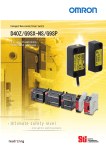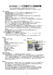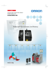
1
䠄㻝㻞䠅」ᩘ䛾䝇䜲䝑䝏䜢㞄᥋䛩䜛ሙྜ䚸㻡㻜㼙㼙௨ୖ䛾㛫㝸䜢✵䛡䛶䛟䛰䛥䛔䚹 ᐃ᱁㻛ᛶ⬟ 㻟 䝟䝣䜷䞊䝬䞁䝇䝺䝧䝹䛸Ᏻ䜹䝔䝂䝸䛻䛴䛔䛶 䖃ᐃ᱁ 㻡㻜㼙㼙௨ୖ ᙧ㻰㻠㻜㼆㻙㻝㻯䕕 㡯┠ ᙧ D40Z ᑠᙧ㠀᥋ゐᘧ䝗䜰䝇䜲䝑䝏 Japanese 䠄㻝㻟䠅䜺䞊䝗䝗䜰䛜㛤䛔䛶䛔䜛䛸䛝䛿ᖖ䛻ᶵᲔ䛜Ṇ䛧䛶䛔䜛䛣䛸䜢☜ㄆ䛧䛶 䛟䛰䛥䛔䚹 ྲྀᢅㄝ᫂᭩ 2137840-7B 㻱㻯㐺ྜᐉゝ 䜸䝮䝻䞁䛿ᙧ㻰㻠㻜㼆䛜௨ୗ䛾㻱㻯ᣦ௧せồ䛻㐺ྜ䛧䛶䛔䜛䛣䛸䜢ᐉ ゝ䛧䜎䛩䚹㻌㻌 㻌ᶵᲔᣦ௧㻌㻞㻜㻜㻢㻛㻠㻞㻛㻱㻯 㻌㻱㻹㻯ᣦ௧㻌㻞㻜㻜㻠㻛㻝㻜㻤㻛㻱㻯 Ᏻୖ䛾䛤ὀព 䖃㆙࿌⾲♧䛾ព ṇ䛧䛔ྲྀᢅ䛔䜢䛧䛺䛡䜜䜀䚸䛣䛾༴㝤䛾䛯䜑䛻䚸 ㍍യ䞉୰⛬ᗘ䛾യᐖ䜢㈇䛳䛯䜚䚸୍䛾ሙྜ䛻 䛿㔜യ䜔Ṛஸ䛻⮳䜛ᜍ䜜䛜䛒䜚䜎䛩䚹䜎䛯䚸ྠ ᵝ䛻㔜䛺≀ⓗᦆᐖ䜢ཷ䛡䜛ᜍ䜜䛜䛒䜚䜎䛩䚹 㻰㻯㻞㻠㼂㻌㻗㻝㻜㻑㻌㻛㻌㻙㻝㻡㻑 ᾘ㈝㟁ຊ㻌䠄ὀ㻝䠅 㻌 㻜㻚㻡㼃௨ୗ 䝣䜷䝖䜹䝥䝷ฟຊ 㻰㻯㻞㻠㼂㻌㈇Ⲵ㟁ὶ䠖㻌㻝㻜㼙㻭 ⿵ຓฟຊ ᳨ᰝ䛸ಖᏲ 䖃ᛶ⬟ 㡯┠ 䠄㻝㻠䠅䝇䜲䝑䝏䛚䜘䜃䜰䜽䝏䝳䜶䞊䝍䜢㔠ᒓ㒊䛻ྲྀ䜚䛡䜛䛸䚸ືస㊥㞳䛻ᙳ 㡪䛜⏕䛨䜎䛩䚹䜎䛯䚸ᙉ䛔㟁Ἴ䜔☢⏺䜢Ⓨ⏕䛩䜛ᶵჾ䛜࿘ᅖ䛻䛒䜛䛸䚸 㔠ᒓ㒊䜢䛧䛶ືస㊥㞳䛻ᙳ㡪䜢ཬ䜌䛩ྍ⬟ᛶ䛜䛒䜚䜎䛩䚹䝇䜲䝑䝏䛚 䜘䜃䜰䜽䝏䝳䜶䞊䝍䜢㔠ᒓ㒊䛻┤᥋ྲྀ䜚䛡䛺䛔䛷䛟䛰䛥䛔䚹 㔠ᒓ㒊䛻ྲྀ䜚䛡䛶䛤⏝䛻䛺䜛ሙྜ䛻䛿๓䛻ᙳ㡪䜢☜ㄆ䛾ୖ䚸䛤⏝䛟 䛰䛥䛔䚹ྲྀ㒊䛾㔠ᒓ䛻䜘䜛ືస㊥㞳䛾ᙳ㡪䛾ཧ⪃್䛿௨ୗ䛾䛸䛚䜚䛷䛩䚹 ྲྀ䜚䛡䜛㔠ᒓ㒊䛾ᮦ㉁ ືస㊥㞳 㕲 ᮏ᮶䛾್䛾⣙㻣㻡㻑 䜰䝹䝭 ᮏ᮶䛾್䛾⣙㻤㻡㻑 䝇䝔䞁䝺䝇 ᮏ᮶䛾್䛾⣙㻤㻡㻑 ࿘ᅖ㔠ᒓ䛛䜙䝇䜲䝑䝏䞉䜰䜽䝏䝳䜶䞊䝍ᮏయ䜢㻝㻜㼙㼙௨ୖ㞳䛧䛶䛤⏝䛔 䛯䛰䛟䛣䛸䜢᥎ዡ䛧䜎䛩䚹 䠄㻝㻡䠅䝇䜲䝑䝏䛚䜘䜃䜰䜽䝏䝳䜶䞊䝍䛾タ⨨䛻䛿㻹㻠䛽䛨䜢⏝䛔䚸ᗙ㔠䜢䛳䛶 つᐃ䛾⥾䝖䝹䜽䛷ྲྀ䜚䛡䜢䛚䛣䛺䛳䛶䛟䛰䛥䛔䚹ྲྀ䜚䛴䛡䛸ヨ㐠㌿䛜 ᚋ䚸䝇䜲䝑䝏䛸䜰䜽䝏䝳䜶䞊䝍䛾ᅛᐃ䛽䛨䛿䚸ኚ᭦㜵Ṇ䝽䝙䝇䛒䜛䛔 䛿ྠ➼䛾䝁䞁䝟䜴䞁䝗䛻䛶䛽䛨⦆䜏㜵Ṇ䜢ᐇ䛧䛶䛟䛰䛥䛔䚹䛽䛨ᅛᐃ ⏝᎘Ẽᛶ䝁䞁䝟䜴䞁䝗䛿䜿䞊䝇䛻᥋ゐ䛩䜛䛸䝥䝷䝇䝏䝑䜽䜿䞊䝇䜢യ䜑 䜎䛩䚹 䜰䜽䝏䝳䜶䞊䝍 つ᱁ ᙧ㻰㻠㻜㼆䛿௨ୗ䛾つ᱁䛻ᚑ䛔䚸タィ㻛〇㐀䛥䜜䛶䛔䜎䛩䚹㻌㻌 㻱㻺㻥㻡㻠㻙㻝㻌㻯㼍㼠㻚㻌㻠㻌㻔ᙧ㻳㻥㻿㼄㻙㻺㻿䕕⏝㻕 㻱㻺㻌㻵㻿㻻㻝㻟㻤㻠㻥㻙㻝㻦㻞㻜㻜㻤㻌㻯㼍㼠㻚㻌㻠㻌㻼㻸㻌㼑㻌㻔ᙧ㻳㻥㻿㼄㻙㻺㻿䕕⏝㻕㻘 㻵㻱㻯㻛㻱㻺㻢㻝㻡㻜㻤㻌㻿㻵㻸㻟㻌㻔ᙧ㻳㻥㻿㼄㻙㻺㻿䕕⏝㻕㻘 㻵㻱㻯㻛㻱㻺㻢㻜㻥㻠㻣㻙㻡㻙㻟㻌㻼㻰㻲㻙㻹㻌㻔ᙧ㻳㻥㻿㼄㻙㻺㻿䕕⏝㻕㻘 㻵㻱㻯㻛㻱㻺㻢㻝㻜㻜㻜㻙㻢㻙㻠㻘㻌㻱㻺㻝㻜㻤㻤㻘㻌㻌 㼁㻸㻡㻜㻤㻘㻌㻯㻭㻺㻛㻯㻿㻭㻌㻯㻞㻞㻚㻞㻌㻺㼛㻚㻝㻠㻌 㟁※㟁ᅽ㻌 M4 1N.m ືస≉ᛶ 䛿䛨䜑䛻 䛣䛾䛯䜃䛿䚸ᙧ㻰㻠㻜㼆ᑠᆺ㠀᥋ゐᘧ䝗䜰䝇䜲䝑䝏䜢䛚㈙䛔ୖ 䛢䛔䛯䛰䛝䜎䛧䛶䚸䜎䛣䛸䛻䛒䜚䛜䛸䛖䛤䛦䛔䜎䛩䚹 䛣䛾ྲྀᢅㄝ᫂᭩䛷䛿䚸ᙧ㻰㻠㻜㼆䜢⏝䛩䜛ୖ䛷䚸ᚲせ䛺ᶵ⬟䚸 ᛶ⬟䚸⏝᪉ἲ䛺䛹䛾ሗ䜢グ㍕䛧䛶䛔䜎䛩䚹 ᙧ㻰㻠㻜㼆䜢䛤⏝䛻㝿䛧䛶ୗグ䛾䛣䛸䜢Ᏺ䛳䛶䛟䛰䛥䛔䚹 䞉ᙧ㻰㻠㻜㼆䛿㟁Ẽ䛾▱㆑䜢᭷䛩䜛ᑓ㛛ᐙ䛜ᢅ䛳䛶䛟䛰䛥䛔䚹 䞉䛣䛾ྲྀᢅㄝ᫂᭩䜢䜘䛟䛚ㄞ䜏䛻䛺䜚䚸༑ศ䛻䛤⌮ゎ䛾䛖䛘䚸 ṇ䛧䛟䛤⏝䛟䛰䛥䛔䚹 䞉䛣䛾ྲྀᢅㄝ᫂᭩䛿䛔䛴䛷䜒ཧ↷䛷䛝䜛䜘䛖ษ䛻ಖ⟶䛟䛰 䛥䛔䚹 ᙧ㻰㻠㻜㼆䛿ᙧ㻳㻥㻿㼄㻙㻺㻿䕕䛸⤌䜏ྜ䜟䛫䛶䛤⏝䛔䛯䛰䛟䛣䛸䛻䜘䜚䚸Ḣᕞ つ᱁㻱㻺㻌㻵㻿㻻㻝㻟㻤㻠㻥㻙㻝䜘䜚せồ䛥䜜䜛䝟䝣䜷䞊䝬䞁䝇䝺䝧䝹㼑䚸Ᏻ䜹䝔䝂䝸㻠 䛾⎔ቃ䛻㐺⏝䛩䜛䛜䛷䛝䜎䛩䚹 䛯䛰䛧䚸䛣䛾タᐃ䛿ᙜ♫䛜ᥦ♧䛧䛶䛔䜎䛩ᅇ㊰䜢䜒䛸䛻ุᐃ䛥䜜䛯䜒䛾 䛷䛒䜚䚸䛤⏝≧ἣ䛻䜘䛳䛶䛿ᙜ䛶䛿䜎䜙䛺䛔ሙྜ䛜䛒䜚䜎䛩䚹䝟䝣䜷䞊䝬 䞁䝇䝺䝧䝹䛸Ᏻ䜹䝔䝂䝸䛿Ᏻไᚚ䝅䝇䝔䝮య䛷ุᐃ䛥䜜䜎䛩䛾䛷䚸 䛤⏝䛾㝿䛻䛿タ⨨䚸᳨ᰝ䚸ಖᏲ䜢ṇ䛧䛟ᐇ⾜䛧䚸༑ศ䛤☜ㄆ䛔䛯䛰䛝䜎 䛩䜘䛖䛚㢪䛔䛧䜎䛩䚹 䠄ὀ㻞䠅 ᙧ㻰㻠㻜㼆㻙㻝㻯䕕 ືస㊥㞳䠄㻻㻲㻲䊻㻻㻺䠅 㻡㼙㼙௨ୖ ືస㊥㞳䠄㻻㻺䊻㻻㻲㻲䠅 㻝㻡㼙㼙௨ୗ ᛂᕪ 㻝㻌㻌᳨ฟ㡿ᇦ䚷ཧ↷㻌 㻝㻌㻌᳨ฟ㡿ᇦ䚷ཧ↷㻌 ᗘ䛾ᙳ㡪 ⧞䜚㏉䛧⢭ᗘ 㻗㻞㻟䉝䛾ືస㊥㞳䛾㼼㻝㻜㻑௨ୗ ᛂ⟅㛫䠄㻻㻺䊻㻻㻲㻲䠅㻔ὀ㻟䠅 ືస㛫䠄㻻㻲㻲䊻㻻㻺䠅㻔ὀ㻟䠅 ⏝࿘ᅖ ᗘ 䠄㻝㻢䠅㓄⥺䛻䛴䛔䛶 㻝㻚㻌㓄⥺⏝㟁⥺䝃䜲䝈䛿ୗグ䛾䜒䛾䜢⏝䛧䛶䛟䛰䛥䛔䚹 䚷䜚⥺䠄㻲㼘㼑㼤㼕㼎㼘㼑㻌㼣㼕㼞㼑䠅䠖㻜㻚㻞䡚㻞㻚㻡㼙㼙2 㻭㼃㻳㻞㻠䡚㻝㻞 䚷༢⥺䠄㻿㼠㼑㼑㼘㻌㼃㼕㼞㼑䠅䠖㻜㻚㻞䡚㻞㻚㻡㼙㼙2 㻭㼃㻳㻞㻠䡚㻝㻞 㻞㻚㻌⿵ຓฟຊ䜢⏝䛧䛺䛔ሙྜ䛿䚸⏝䛧䛺䛔䝸䞊䝗⥺䜢ษ᩿䛧䛶⤯⦕䝔 䞊䝥䜢ᕳ䛟䛺䛹䚸䛾➃Ꮚ䛸᥋ゐ䛧䛺䛔䜘䛖ฎ⌮䛧䛶䛟䛰䛥䛔䚹 㻟㻚㻌㻞㻜㼙௨ୖ䛾䜿䞊䝤䝹䜢㏣ຍ䛷ᩜタ䛩䜛ሙྜ䛿䚸ከⰺ䜿䞊䝤䝹䛻䛶㻌㻌 ⓑ䚸㯮䚸Ⲕ䚸㟷䜿䞊䝤䝹䜢୍ᣓ䛧䛶䛟䛰䛥䛔䚹 䠄㻝㻣䠅ᙧ㻰㻠㻜㼆䛾⥲㓄⥺㛗䛿䚸㻝㻜㻜㼙௨ෆ䛷㓄⥺䛧䛶䛟䛰䛥䛔䚹䛯䛰䛧䚸᥋⥆ྎ ᩘ䛻ᛂ䛨䛶⥲㓄⥺㛗䛿㻞㻜㻜㼙䜎䛷ྍ⬟䛷䛩䚹 ⏝䛩䜛䜿䞊䝤䝹䜎䛯䛿㓄⥺᮲௳䛻䜘䛳䛶䛿䚸㟁ᅽ㝆ୗ䛻䜘䜚ᙧ㻰㻠㻜㼆 䜈䛾౪⤥㟁ᅽ䛜పୗ䛩䜛ሙྜ䛜䛒䜚䜎䛩䚹ᙧ㻰㻠㻜㼆䛾㟁※㟁ᅽ䛜ᐃ᱁ ⠊ᅖ䛷䛒䜛䛛䜢☜ㄆ䛧䛶䛟䛰䛥䛔䚹 ە᥋⥆ྎᩘࡀྎࡲ࡛ࡢ ە᥋⥆ྎᩘࡀྎࡲ࡛ࡢ 㻞㻡㼙㼟௨ୗ 㻝㻜㻜㼙㼟௨ୗ㻌㻌䠄䝇䜲䝑䝏䛸䜰䜽䝏䝳䜶䞊 䝍䛾᳨ฟ㠃㛫䛾㊥㞳䛜㻡㼙㼙䠅 㻙㻝㻜䡚㻗㻢㻡䉝㻌 ⾲♧ⅉ 䝇䜲䝑䝏 ⏝࿘ᅖ‵ᗘ 㻞㻡䡚㻤㻡㻑㻾㻴 ⤯⦕ᢠ䠄㟁㒊୍ᣓ䛸䜿䞊䝇䠅 㻡㻜㻹䃈௨ୖ䠄㻰㻯㻡㻜㻜㼂䝯䜺䠅 ⪏㟁ᅽ䠄㟁㒊୍ᣓ䛸䜿䞊䝇䠅 㻭㻯㻝㻜㻜㻜㼂㻌㻝ศ㛫 ⪏ື ⪏⾪ᧁ ởᰁᗘ እᙧᑍἲ 㻠 䠄䛯䛰䛧䚸ị⤖䛚䜘䜃⤖㟢䛧䛺䛔䛣䛸䠅 䠄༢䠖㼙㼙䠅 䜿䞊䝤䝹ᚄ䠖䃥㻠㻚㻞 ᳨ฟ㠃 䝍䞊䝀䝑䝖䝬䞊䜽 䢳䢰䢷 䢴 㻝㻜䡚㻡㻡䡚㻝㻜㻴㼦㻌∦ᖜ㻜㻚㻣㻡㼙㼙 䢴䢲 㻟㻜㻜㼙㻛㼟2௨ୖ 㻟 㻵㻱㻯㻛㻱㻺㻌㻢㻜㻥㻠㻣㻙㻡㻙㻟‽ᣐ 㻵㻼㻢㻣 ᮦ㉁ 㻼㻮㼀ᶞ⬡ 㻹㻠䛽䛨 㻝㻺䞉㼙 䝇䜲䝑䝏㻌⣙㻝㻣㻡䡃 䜰䜽䝏䝳䜶䞊䝍㻌⣙㻞㻜㼓 ㉁㔞䚷䠄ᙧ㻰㻠㻜㼆㻙㻝㻯㻡䛾ሙྜ䠅 䢴䢯䪻䢹䢰䢴 䢵䢺 䢳䢲䢰䢷 䢳䢸 䜰䜽䝏䝳䜶䞊䝍 䠄༢䠖㼙㼙䠅 ᳨ฟ㠃 䝍䞊䝀䝑䝖䝬䞊䜽 䢳䢴 䢴䢯䪻䢶䢰䢴 (ὀ) 䖃」ᩘྎ᥋⥆䛾㓄⥺ 䖃⿵ຓฟຊ䛾㓄⥺ 㻰㻠㻜㼆㻙㻝㻯䕕 㯤 ⓑ 㯮 Ⲕ 㟷 ⓑ 㯮 Ⲕ 㟷 ⓑ 㯮 Ⲕ 㟷 ᶵᲔ䛜ືస䛧䚸㔜ᗘ䛾ே㌟യᐖ䛜୍䛾ሙྜ㉳䛣䜛 ᜍ䜜䛜䛒䜚䜎䛩䚹 ᡬ䛜㛤䛔䛯≧ែ䛷䜰䜽䝏䝳䜶䞊䝍䜢䝇䜲䝑䝏䛻㏆䛵䛡 䛺䛔䛷䛟䛰䛥䛔䚹 㯤 IN ⓑ 㯮 Ⲕ 㟷 㻝㻢 PLC➼ 䖃ෆ㒊ᅇ㊰ᅗ 㟷 ಙྕྡ 㻻㻺 㯮 㯤 ⅊ 㻙㻟㻡 㻙㻟㻜 㻙㻞㻡 㻙㻞㻜 㻙㻝㻡 㻙㻝㻜 㻙㻡 㻜 䝇䜲䝑䝏䛸䝍䞊䝀䝑䝖䝬䞊䜽䛾୰ᚰ䛛䜙䛾㊥㞳䚷㼄䠄㼙㼙䠅 㻝㻠 㠀᥋ゐᘧ䝗䜰䝇䜲䝑䝏ฟຊ 㯮 䜰䜽䝏䝳䜶䞊䝍᳨▱䚸㠀᥋ゐᘧ䝗䜰䝇䜲䝑䝏ධຊ䛾≧ែ䛻ᚑ䛳䛶䚸 ฟຊ㻻㻺㻛㻻㻲㻲䛧䜎䛩䚹 㟁※ධຊ䠄Ⲕ䚸㟷䠅 䛾␗ᖖ 䝜䜲䝈䚸䜎䛯䛿 ᙧ㻰㻠㻜㼆䛾ᨾ㞀 㻙㻟㻜 㻙㻞㻡 㻙㻞㻜 㻙㻝㻡 㻙㻝㻜 㻙㻡 㻜 㻡 㻝㻜 㻝㻡 㻞㻜 㻞㻡 㻟㻜 䝇䜲䝑䝏䛸䝍䞊䝀䝑䝖䝬䞊䜽䛾୰ᚰ䛛䜙䛾㊥㞳䚷㼆䠄㼙㼙䠅 㼄 㼆 㼅 䝍䞊䝀䝑䝖䝬䞊䜽 ὀ㻝㻌ືస㊥㞳䛿䚸䝇䜲䝑䝏䛸䜰䜽䝏䝳䜶䞊䝍䛾᳨ฟ㠃㛫䛾㊥㞳䜢♧䛧䜎䛩䚹 ὀ㻞㻌ᅗ䛿࿘ᅖ ᗘ㻗㻞㻟䉝䛻䛚䛡䜛௦⾲䝕䞊䝍䛷䛒䜚䚸ືసಖド್䛷䛿䛒䜚 䜎䛫䜣䚹ືస㊥㞳䛿࿘ᅖ䛾㔠ᒓ䞉䝬䜾䝛䝑䝖䜻䝱䝑䝏䜔 ᗘ䛾ᙳ㡪䛷ኚ 䛩䜛䛣䛸䛜䛒䜚䜎䛩䚹 ὀ䠏㻌䝇䜲䝑䝏䛚䜘䜃䜰䜽䝏䝳䜶䞊䝍䛾᳨ฟ㠃௨እ䛾㠃䛷᳨ฟ䛩䜛䛣䛸䛜䛒䜚 䜎䛩䚹䛤⏝䛾㝿䛿䛂㻌㻞㻌䝇䜲䝑䝏䛸䜰䜽䝏䝳䜶䞊䝍䛾ືస䛻䛴䛔䛶䛃䜢ཧ ⪃䛻䚸䝇䜲䝑䝏䛸䜰䜽䝏䝳䜶䞊䝍䛾᳨ฟ㠃䛜ྥ䛝ྜ䛖䜘䛖䛻タ⨨䛟䛰䛥䛔䚹 㯮䜿䞊䝤䝹䛸䛾䜿䞊䝤䝹䛸䛜▷⤡䛧䛶䛔䜛ྍ⬟ᛶ䛜䛒䜚䜎䛩䚹 㯮䜿䞊䝤䝹䛜䛾䜿䞊䝤䝹䛸▷⤡䛧䛶䛔䛺䛔䛛☜ㄆ䛧䛶䛟䛰䛥䛔䚹䛂㻌㻡㻌ᙧ㻰㻠㻜㼆䛾㓄⥺䛃䜢ཧ↷䛟䛰䛥䛔䚹 ㉥㻞⛊䛻㻞ᅇⅬ⁛ 㐺ᙜ䛺䜰䜽䝏䝳䜶䞊䝍䛜㏆᥋䛧䛶䛔䜛ྍ⬟ᛶ䛜䛒䜚䜎䛩䚹 䝉䞁䝅䞁䜾ᶵ⬟䛾␗ᖖ ᑓ⏝䜰䜽䝏䝳䜶䞊䝍䜢⏝䛧䛶䛟䛰䛥䛔䚹 ㉥㻞⛊䛻㻟ᅇⅬ⁛ 㠀᥋ゐᘧ䝗䜰䝇䜲䝑䝏 ධຊ䠄ⓑ䠅䛾␗ᖖ ⓑ䜿䞊䝤䝹䛻␗ᖖ䛺ಙྕ䛜ධຊ䛥䜜䛶䛔䜛ྍ⬟ᛶ䛜䛒䜚䜎䛩䚹 ⓑ䜿䞊䝤䝹䛜ṇ䛧䛟㓄⥺䛥䜜䛶䛔䜛䛛☜ㄆ䛧䛶䛟䛰䛥䛔䚹䛂㻌㻡㻌ᙧ㻰㻠㻜㼆䛾㓄⥺䛃䜢ཧ↷䛟䛰䛥䛔䚹 䛾ᙧ㻰㻠㻜㼆䛜 㻻㻲㻲≧ែ ⓑ䜿䞊䝤䝹䛾ಙྕ䛜㻻㻲㻲≧ែ䛾ྍ⬟ᛶ䛜䛒䜚䜎䛩䚹 ⓑ䜿䞊䝤䝹䛻᥋⥆䛧䛶䛔䜛䛾ᙧ㻰㻠㻜㼆䛾タ⨨≧ែ䛚䜘䜃㓄⥺≧ែ䜢☜ㄆ䛧䛶䛟䛰䛥䛔䚹 䛂㻌㻞㻌䝇䜲䝑䝏䛸䜰䜽䝏䝳䜶䞊䝍䛾ືస䛻䛴䛔䛶䛃䛚䜘䜃䛂㻌㻡㻌ᙧ㻰㻠㻜㼆䛾㓄⥺䛃䜢ཧ↷䛟䛰䛥䛔䚹 㠀᥋ゐᘧ䝗䜰䝇䜲䝑䝏 ධຊ䠄ⓑ䠅䛾␗ᖖ ⓑ䜿䞊䝤䝹䛜᩿⥺䛧䛶䛔䜛ྍ⬟ᛶ䛜䛒䜚䜎䛩䚹 ⓑ䜿䞊䝤䝹䛜ṇ䛧䛟㓄⥺䛥䜜䛶䛔䜛䛛☜ㄆ䛧䛶䛟䛰䛥䛔䚹䛂㻌㻡㻌ᙧ㻰㻠㻜㼆䛾㓄⥺䛃䜢ཧ↷䛟䛰䛥䛔䚹 㯤ᖖⅬ⁛ ㉥Ⅼⅉ㻌䠄ὀ㻞䠅 䜰䜽䝏䝳䜶䞊䝍 䜰䜽䝏䝳䜶䞊䝍 䖃䝇䜲䝑䝏䛸䜰䜽䝏䝳䜶䞊䝍䛾ືస᪉ྥ ὀ㻝 ὀ㻝㻌ືస᪉ྥ䜢᳨ฟ㠃䛻ἢ䛳䛶䛤⏝䛻䛺䜛ሙྜ䛿䚸䝃䜲䝗䝻䞊䝤䛾ᙳ㡪䜢ཷ䛡䛺䛔 䜘䛖䛻䝇䜲䝑䝏䛸䜰䜽䝏䝳䜶䞊䝍䜢ྲྀ䜚䛡䛶䛤⏝䛟䛰䛥䛔䚹 䖃㻸㻱㻰⾲♧ 㻸㻱㻰Ⰽ ≧ែ 㯤 㯤Ⅼⅉ 䠄ὀ㻟䠅 䜰䜽䝏䝳䜶䞊䝍䛾␗ᖖ 䜰䜽䝏䝳䜶䞊䝍䛜ᨾ㞀䛧䛶䛔䜛ྍ⬟ᛶ䛜䛒䜚䜎䛩䚹〇ရ䜢䛧䛶䛟䛰䛥䛔䚹 㠀᥋ゐᘧ䝗䜰䝇䜲䝑䝏 ධຊ䠄ⓑ䠅䛾␗ᖖ ᙧ㻳㻥㻿㼄㻙㻺㻿䕕䛾㻰㻝➃Ꮚ䛻᥋⥆䛧䛯ⓑ䜿䞊䝤䝹䛸䛾䜿䞊䝤䝹䛸䛜▷⤡䛧䛶䛔䜛ྍ⬟ᛶ䛜䛒䜚䜎䛩䚹 ᙧ㻳㻥㻿㼄㻙㻺㻿䕕䛾㻰㻝➃Ꮚ䛻᥋⥆䛧䛯ⓑ䜿䞊䝤䝹䛜䛾䜿䞊䝤䝹䛸▷⤡䛧䛶䛔䛺䛔䛛☜ㄆ䛧䛶䛟䛰䛥䛔䚹 䛂㻌㻡㻌ᙧ㻰㻠㻜㼆䛾㓄⥺䛃䜢ཧ↷䛟䛰䛥䛔䚹 㠀᥋ゐᘧ䝗䜰䝇䜲䝑䝏 ฟຊ䠄㯮䠅䛾␗ᖖ ᙧ㻳㻥㻿㼄㻙㻺㻿䕕䛾㻰㻞➃Ꮚ䛻᥋⥆䛧䛯㯮䜿䞊䝤䝹䛜᩿⥺䛧䛶䛔䜛ྍ⬟ᛶ䛜䛒䜚䜎䛩䚹 ᙧ㻳㻥㻿㼄㻙㻺㻿䕕䛾㻰㻞➃Ꮚ䛻᥋⥆䛧䛯㯮䜿䞊䝤䝹䛜ṇ䛧䛟㓄⥺䛥䜜䛶䛔䜛䛛☜ㄆ䛧䛶䛟䛰䛥䛔䚹 䛂㻌㻡㻌ᙧ㻰㻠㻜㼆䛾㓄⥺䛃䜢ཧ↷䛟䛰䛥䛔䚹 ὀ㻝㻌䛾ཎᅉ䛸䛧䛶䚸ෆ㒊ᅇ㊰䛜ᨾ㞀䛧䛯ྍ⬟ᛶ䛜䛒䜚䜎䛩䚹䛭䛾ሙྜ䛿〇ရ䜢䛧䛶䛟䛰䛥䛔䚹 䚷䚷㻌㻌䜎䛯䚸㐣䛺䝜䜲䝈䛾ᙳ㡪䜢ཷ䛡䛶䛔䜛ྍ⬟ᛶ䛜䛒䜚䜎䛩䚹䛭䛾ሙྜ䛿䚸࿘ᅖ䛾䝜䜲䝈⎔ቃ䜢☜ㄆ䛧䛶䛟䛰䛥䛔䚹 ὀ㻞㻌䜺䞊䝗䝗䜰䛜㛢䛨䛶䛔䜛䠄䜰䜽䝏䝳䜶䞊䝍᳨▱䠅ሙྜ䜢♧䛧䜎䛩䚹 ὀ㻟㻌䜺䞊䝗䝗䜰䛜㛢䛨䛶䛔䜛䠄䜰䜽䝏䝳䜶䞊䝍᳨▱䠅䛻䜒㛵䜟䜙䛪䚸䝅䝇䝔䝮䛜Ṇ䛧䛯ሙྜ䜢♧䛧䜎䛩䚹 䝇䜲䝑䝏 ㉥ ෆ㒊ᅇ㊰ᨾ㞀䛾ྍ⬟ᛶ䛜䛒䜚䜎䛩䚹〇ရ䜢䛧䛶䛟䛰䛥䛔䚹 㠀᥋ゐᘧ䝗䜰䝇䜲䝑䝏 ฟຊ䠄㯮䠅䛾␗ᖖ 䝇䜲䝑䝏䛸䜰䜽䝏䝳䜶䞊䝍䛾ືస䛻䛴䛔䛶 䖃䝇䜲䝑䝏䛸䜰䜽䝏䝳䜶䞊䝍䛾ྲྀ䜚䛴䛡᪉ྥ 㐣䛺䝜䜲䝈䛾ᙳ㡪䜢ཷ䛡䛶䛔䜛ྍ⬟ᛶ䛜䛒䜚䜎䛩䚹࿘ᅖ䛾䝜䜲䝈⎔ቃ䜢☜ㄆ䛧䛶䛟䛰䛥䛔䚹 ㉥㻞⛊䛻䠍ᅇⅬ⁛ 㻜 ࿘ᅖ ᗘ䛾ᙳ㡪㻔䉝䠅 ᙧ㻰㻠㻜㼆䜈䛾౪⤥㟁ᅽ䛜㊊䛧䛶䛔䜛ྍ⬟ᛶ䛜䛒䜚䜎䛩䚹ᙧ㻰㻠㻜㼆䛾㟁※䠄Ⲕ㻙㟷䜿䞊䝤䝹㛫䠅㟁ᅽ䛜 ᐃ᱁⠊ᅖ䛷䛒䜛䛛䜢☜ㄆ䛧䛶䛟䛰䛥䛔䚹䛂㻌㻟㻌ᐃ᱁㻛ᛶ⬟䛃䜢ཧ↷䛟䛰䛥䛔䚹 㟁※ධຊ䠄Ⲕ䚸㟷䠅 䛾␗ᖖ ㉥ᖖⅬ⁛ ᳨ฟ㠃 㻢 䝇䜲䝑䝏 䜰䜽䝏䝳䜶䞊䝍᳨▱≧ែ䛻ᚑ䛳䛶ฟຊ䛧䜎䛩䚹 䜶䝷䞊᳨ฟ䛿䜰䜽䝏䝳䜶䞊䝍᳨▱≧ែ䛻㛵䜟䜙䛪ฟຊ㻻㻲㻲䛧䜎䛩䚹 ᙧ㻰㻠㻜㼆䜈䛾౪⤥㟁ᅽ䛜㊊䛧䛶䛔䜛ྍ⬟ᛶ䛜䛒䜚䜎䛩䚹ᙧ㻰㻠㻜㼆䛾㟁※䠄Ⲕ㻙㟷䜿䞊䝤䝹㛫䠅㟁ᅽ䛜 ᐃ᱁⠊ᅖ䛷䛒䜛䛛䜢☜ㄆ䛧䛶䛟䛰䛥䛔䚹䛂㻌㻟㻌ᐃ᱁㻛ᛶ⬟䛃䜢ཧ↷䛟䛰䛥䛔䚹 つᐃ䛾㓄⥺㛗䜎䛯䛿㟁⥺䝃䜲䝈䛻䛶㓄⥺䛥䜜䛶䛔䛺䛔ྍ⬟ᛶ䛜䛒䜚䜎䛩䚹 㓄⥺㛗䛚䜘䜃㟁⥺䝃䜲䝈䜢☜ㄆ䛧䛶䛟䛰䛥䛔䚹䛂⏝ୖ䛾ὀព䛃䜢ཧ↷䛟䛰䛥䛔䚹 㻤 㼄㻩㻜㻘㻌㼆㻩㻜 ⅊ つᐃ䛾㓄⥺㛗䜎䛯䛿㟁⥺䝃䜲䝈䛻䛶㓄⥺䛥䜜䛶䛔䛺䛔ྍ⬟ᛶ䛜䛒䜚䜎䛩䚹 㓄⥺㛗䛚䜘䜃㟁⥺䝃䜲䝈䜢☜ㄆ䛧䛶䛟䛰䛥䛔䚹䛂⏝ୖ䛾ὀព䛃䜢ཧ↷䛟䛰䛥䛔䚹 㻞 㻻㻲㻲 㻞 㯤 ཎᅉ䛸ᑐ⟇䚷䠄ὀ㻝䠅 ᾘⅉ 㻻㻺 㼅 䠄㼙㼙䠅 㻠 ᙧ㻰㻠㻜㼆䛻㟁※౪⤥䛧䜎䛩䚹 䝖䝷䝤䝹䝅䝳䞊䝔䜱䞁䜾 㻻㻲㻲 㻝㻞 㻝㻜 ືసᴫせ 㠀᥋ゐᘧ䝗䜰䝇䜲䝑䝏ධຊ䛜㻻㻺≧ែ䛷䛒䜛䛣䛸䛜䚸 㠀᥋ゐᘧ䝗䜰䝇䜲䝑䝏ฟຊ䛜㻻㻺≧ែ䛸䛺䜛䛯䜑䛾ᚲせ᮲௳䛸䛺䜚䜎䛩䚹 㻻㻺 㻤 㻡 㻝㻜 㻝㻡 㻞㻜 㻞㻡 㻟㻜 㻟㻡 㟷 ⓑ ⿵ຓฟຊ 㻜 㻜 Ⲕ 䞊 㠀᥋ゐᘧ䝗䜰䝇䜲䝑䝏ධຊ 㻢 䝃䜲䝗䝻䞊䝤 䝃䜲䝗䝻䞊䝤 㻞 䠇 ⓑ 㼅 䠄㼙㼙䠅 㻠 㻠 䜿䞊䝤䝹Ⰽ 㠀᥋ゐᘧ䝗䜰䝇䜲䝑䝏 㟁※ධຊ 㟁※ධຊ䛾㓄⥺␗ᖖ䛜⪃䛘䜙䜜䜎䛩䚹Ⲕ䛚䜘䜃㟷䜿䞊䝤䝹䛜᩿⥺䞉▷⤡䛧䛶䛔䛺䛔䛛☜ㄆ䛧䛶䛟䛰䛥䛔䚹 䛂㻌㻡㻌ᙧ㻰㻠㻜㼆䛾㓄⥺䛃䜢ཧ↷䛟䛰䛥䛔䚹 㻝㻜 㻤 㼅 㻢 䠄㼙㼙䠅 㻞 䖃ධฟຊ䛾㓄⥺䛻䛴䛔䛶 Ⲕ 㻝㻞 㻻㻲㻲 㻝㻜 ὀ䠍䠊⿵ຓฟຊ䛾㈇Ⲵ䛿㻝㻜㼙㻭௨ୗ䛸䛧䛶䛟䛰䛥䛔䚹 㻌㻌㻌㻌㻌㻌㻌㻌㻌᥋⥆䜢㛫㐪䛘䜛䛸⿵ຓฟຊᅇ㊰䛜ᨾ㞀䛩䜛ᜍ䜜䛜䛒䜚䜎䛩䚹 ὀ㻞䠊䛭䛾䛾ヲ⣽䛺㓄⥺䛿ᙧ㻰㻠㻜㼆䛾䜹䝍䝻䜾䜢ཧ↷䛟䛰䛥䛔䚹 G9SX-NS202 G9SX-NSA222 ⾲♧ⅉ 㻝㻠 㻝㻞 COM 㻰㻯㻞㻠㼂 㻝㻢 㻝㻠 PLC➼ G9SX-NS202 G9SX-NSA222 D1 D2 D3 D4 1 ᳨ฟ㡿ᇦ䠄≉ᛶ䝕䞊䝍䠅 ືస㊥㞳 䠄㻝䠅㻱㻺㻌㻵㻿㻻㻝㻟㻤㻠㻥㻙㻝䛾せồ㡯䜢‶䛯䛩䛯䜑䛻䚸ᚲ䛪ᑓ⏝䜰䜽䝏䝳䜶䞊䝍 䛚䜘䜃ᑓ⏝䝁䞁䝖䝻䞊䝷䛸⤌䜏ྜ䜟䛫䛶䛤⏝䛟䛰䛥䛔䚹 䠄㻞䠅ྲྀ䜚ᢅ䛔䛻䛴䛔䛶 㻌㻌㻌㻌㻌〇ရ䜢ⴠୗ䛥䛫䛯䜚䚸␗ᖖ䛺ື⾪ᧁ䜢ຍ䛘䛺䛔䛷䛟䛰䛥䛔䚹ᨾ㞀䜔ㄗ ືస䛾ཎᅉ䛸䛺䜚䜎䛩䚹 䠄㻟䠅ಖ⟶䚸タ⨨ሙᡤ䛻䛴䛔䛶 㻌㻌㻌㻌㻌ୗグ䛾ሙᡤ䛻䛿ᨾ㞀䜔ㄗືస䛾ཎᅉ䛸䛺䜚䜎䛩䛾䛷ಖ⟶䚸タ⨨䜢䛧䛺 䛔䛷䛟䛰䛥䛔䚹 㻌㻌㻌㻌㻌㻌㻌㻌㻝㻚㻌┤᥋᪥ග䛜ᙜ䛯䜛ሙᡤ䚹 㻌㻌㻌㻌㻌㻌㻌㻌㻞㻚㻌࿘ᅖ ᗘ䛜㻙㻝㻜䡚㻗㻢㻡䉝䛾⠊ᅖ䜢㉺䛘䜛ሙᡤ䚹 㻌㻟㻚㻌┦ᑐ‵ᗘ䛜㻞㻡䡚㻤㻡䠂㻾㻴䛾⠊ᅖ䜢㉺䛘䜛ሙᡤ䚸 ᗘኚ䛜ᛴ⃭䛷⤖㟢䛩䜛䜘䛖䛺ሙᡤ䚹 㻌㻌㻌㻌㻌㻌㻌㻌㻠㻚㻌⭉㣗ᛶ䜺䝇䜔ྍ⇞ᛶ䜺䝇䛾䛒䜛ሙᡤ䚹 㻌㻌㻌㻌㻌㻌㻌㻌㻡㻚㻌ᮏయ䛻ᐃ᱁್௨ୖ䛾ື䜔⾪ᧁ䛜ఏ䜟䜛ሙᡤ䚹 㻌㻌㻌㻌㻌㻌㻌㻌㻢㻚㻌Ἔ䚸⸆ရ䛺䛹䛾㣕ἓ䛜䛒䜛ሙᡤ䚹 㻌㻌㻌㻌㻌㻌㻌㻌㻣㻚㻌ሻᇕ䚸ሷศ䚸㕲⢊䛾ከ䛔ሙᡤ䚹 㻌㻌㻌㻌㻌㻌㻌㻌㻤㻚㻌㕲ᒌ䜔㕲⢊䛺䛹䛜┤᥋䜅䜚䛛䛛䜛ሙᡤ䚹 䠄㻠䠅ᙧ㻰㻠㻜㼆䜢ᶆ㧗㻝㻜㻜㻜㼙௨ୖ䛾ሙᡤ䛷⏝䛧䛺䛔䛷䛟䛰䛥䛔䚹 䠄㻡䠅ᙧ㻰㻠㻜㼆䛾ධฟຊ⥺䛻䛾䝇䜲䝑䝏䜔䝉䞁䝃䜢᥋⥆䛧䛶⏝䛧䛺䛔䛷䛟 䛰䛥䛔䚹 䠄㻢䠅䝇䜲䝑䝏䛾䜢䛚䛣䛺䛖ሙྜ䛻䛿䚸ᚲ䛪ᙧ㻰㻠㻜㼆䛚䜘䜃ᙧ㻰㻠㻜㼆䛻᥋⥆ 䛧䛯䝁䞁䝖䝻䞊䝷䛾㟁※䜢ษ䛳䛯≧ែ䛷䛚䛣䛺䛳䛶䛟䛰䛥䛔䚹ᙧ㻰㻠㻜㼆䛻᥋ ⥆䛥䜜䛯እ㒊⨨䛜ணᮇ䛫䛼ືస䜢䛩䜛ྍ⬟ᛶ䛜䛒䜚䜎䛩䚹 䠄㻣䠅⁐䛾╔䛻䛴䛔䛶 㻌㻌㻌㻌㻌〇ရ䛻䜰䝹䝁䞊䝹䚸䝅䞁䝘䞊䚸䝖䝸䜽䝻䝻䝧䞁䝊䞁䚸䜺䝋䝸䞁䛺䛹䛾⁐ 䛜╔䛧䛺䛔䜘䛖䛻䛧䛶䛟䛰䛥䛔䚹⁐䛻䜘䜚䚸䝬䞊䜻䞁䜾䛾ᾘ䛘䜔䚸㒊 ရ䛾ຎ䜢ᘬ䛝㉳䛣䛩ཎᅉ䛸䛺䜚䜎䛩䚹 䠄㻤䠅ᙧ㻰㻠㻜㼆䜢㻝㻚㻡㼙㼀௨ୖ䛾☢⏺ෆ䛷⏝䛧䛺䛔䛷䛟䛰䛥䛔䚹ṇᖖ䛻ືస䛧䜎 䛫䜣䚹 䠄㻥䠅Ỉ୰䛷䛾⏝䜔ᖖỈ䛜䛛䛛䜛⎔ቃ䛷䛿⏝䛧䛺䛔䛷䛟䛰䛥䛔䚹ෆ㒊 䛻Ỉ䛜ᾐධ䛩䜛ᜍ䜜䛜䛒䜚䜎䛩䚹䠄ᮏ䝇䜲䝑䝏䛾ಖㆤᵓ㐀㻵㻼㻢㻣䛸䛿䚸୍ ᐃ㛫Ỉ୰䛻ᨺ⨨䛧䛯ᚋ䛾Ỉ䛾ᾐධ䜢☜ㄆ䛩䜛䜒䛾䛷䛩䚹䠅 䠄㻝㻜䠅䝇䜲䝑䝏ᮏయ䜢䝇䝖䝑䝟䞊䛸䛧䛶⏝䛧䛺䛔䛷䛟䛰䛥䛔䚹䝇䝖䝑䝟䞊䜢タ ⨨䛩䜛䛣䛸䛻䜘䜚䚸䝇䜲䝑䝏䛚䜘䜃䜰䜽䝏䝳䜶䞊䝍䜢ಖㆤ䛧䛶䛟䛰䛥䛔䚹䝇 䜲䝑䝏䛸䜰䜽䝏䝳䜶䞊䝍䛾㛫㝸䛿㻝㼙㼙௨ୖ㞳䛧䛶䛟䛰䛥䛔䚹 䠄㻝㻝䠅䜺䞊䝗䝗䜰䛾㛤ཱྀ㒊䛜Ᏻ䜢☜ಖ䛷䛝䜛㊥㞳ෆ䛷᳨ฟ䛷䛝䜛䜘䛖䛻䚸䝇 䜲䝑䝏䛸䜰䜽䝏䝳䜶䞊䝍䜢ྲྀ䜚䛴䛡䛶䛟䛰䛥䛔䚹 G9SX-NS202 G9SX-NSA222 ὀ. 〇ရ㛫ࡢ㓄⥺㛗ࡣ100m௨ୗࡋ࡚ࡃࡔࡉ࠸ࠋ 䠄㻝㻤䠅䛣䛾〇ရ䛿䜽䝷䝇㻭䛷䛩䚹ᐙᗞ⏝⎔ቃ䛻䛚䛔䛶䛣䛾〇ရ䛿㟁Ἴ㞀ᐖ䜢 ㉳䛣䛩䛜䛒䜚䜎䛩䚹䛣䛾ሙྜ䛿⏝⪅䛜༑ศ䛺ᑐ⟇䜢ㅮ䛨䛶䛟䛰䛥䛔䚹 䠄㻝㻥䠅㻾㻲㻵㻰䝅䝇䝔䝮䚸㏆᥋䝉䞁䝃䚸䝰䞊䝍䚸䜲䞁䝞䞊䝍䚸䝇䜲䝑䝏䞁䜾㟁※䛺䛹 ᙉ䛔㟁Ἴ䜔☢⏺䜢Ⓨ⏕䛩䜛ᶵჾ䛜࿘ᅖ䛻䛒䜛䛣䛸䛷㻰㻠㻜㼆䛿ṇᖖ䛻ືస 䛧䛺䛔ྍ⬟ᛶ䛜䛒䜚䜎䛩䚹䛣䜜䜙䛾ᶵჾ䛾㏆䛟䛷㻰㻠㻜㼆䜢䛤⏝䛻䛺䜛ሙ ྜ䛻䛿๓䛻ᙳ㡪䜢☜ㄆ䛾ୖ䚸䛤⏝䛟䛰䛥䛔䚹 䠄㻞㻜䠅䜿䞊䝤䝹䛾ྲྀᢅ䛻䛴䛔䛶 㻝㻚䜿䞊䝤䝹䜢᭤䛢䛶㓄⥺䛩䜛ሙྜ䛿䚸䜿䞊䝤䝹እᚄ䛾㻢ಸ௨ୖ䛾᭤䛢༙ ᚄ䜢䛚ዡ䜑䛧䜎䛩䚹 䠎㻚䜿䞊䝤䝹䛻㻡㻜㻺௨ୖ䛾ᘬ䛳ᙇ䜚ຊ䜢ຍ䛘䛺䛔䛷䛟䛰䛥䛔䚹 䠄㻞㻝䠅༴㝤※䜎䛷䛾Ᏻ㊥㞳䜢Ỵᐃ䛩䜛㝿䛻䛿䚸ᛂ⟅㛫䛻䜘䜛㠀᥋ゐᘧ䝗 䜰䝇䜲䝑䝏ฟຊ䛾㐜ᘏ䜢⪃៖䛟䛰䛥䛔䚹 㻔㻞㻞㻕㻌ᙧ㻰㻠㻜㼆䜢⏝䛥䜜䜛㏆䛟䛻䛝䛺䝃䞊䝆䜢Ⓨ⏕䛩䜛⨨䠄䝰䞊䝍䛺䛹䠅 䛜䛒䜛ሙྜ䚸䝃䞊䝆䞉䜰䝤䝋䞊䝞䜢ᙧ㻰㻠㻜㼆䛾㟷䜿䞊䝤䝹䠉ྛಙྕ䜿䞊䝤 䝹䠄ⓑ䚸㯮䚸Ⲕ䠅㛫䛻䚸䛚䜘䜃㯤䜿䞊䝤䝹䠉⅊䜿䞊䝤䝹㛫䛻ᤄධ䛧䛶䛟䛰䛥 䛔䚹⏝䛩䜛䝃䞊䝆䞉䜰䝤䝋䞊䝞䛿௨ୗᵝ䛾䜒䛾䜢᥎ዡ䛔䛯䛧䜎䛩䚹 䚷䚷䚷䞉᭱䝟䝹䝇㟁ຊ䠖㻢㻜㻜㼃䠄㻝㻜㻛㻝㻜㻜㻜䃛㼟䠅௨ୖ 䚷䚷䚷䚷䠄㻵㻱㻯㻢㻝㻜㻜㻜㻙㻠㻙㻡䠄䝃䞊䝆䜲䝭䝳䝙䝔䜱䠅ᑐᛂရ䠅 䚷䚷䚷䞉䝤䝺䜲䜽䝎䜴䞁㟁ᅽ䠖㻞㻣䡚㻟㻟㼂 ືస㊥㞳 ⏝ୖ䛾ὀព G9SX-NS202 G9SX-NSA222 ືస㊥㞳 䠄㻝䠅㓄⥺䜢䛚䛣䛺䛖ሙྜ䛻䛿ᚲ䛪㟁※䜢ษ䛳䛯≧ែ䛷䛚䛣䛺䛳䛶䛟䛰䛥䛔䚹ᮏ ⨨䛻᥋⥆䛥䜜䛯እ㒊⨨䛜ணᮇ䛫䛼ືస䜢䛩䜛ྍ⬟ᛶ䛜䛒䜚䜎䛩䚹 䠄㻞䠅ᘬⅆᛶ䜺䝇䞉⇿Ⓨ䜺䝇䛺䛹䛾㞺ᅖẼ䛷䛿⏝䛧䛺䛔䛷䛟䛰䛥䛔䚹 䠄㻟䠅ධฟຊ➃Ꮚ䛿ṇ䛧䛟㓄⥺䛧䚸✌ാ๓䛻ືస☜ㄆ䜢䛧䛶䛟䛰䛥䛔䚹㓄⥺䜢ㄗ 䜛䛸Ᏻᶵ⬟䜢ᦆ䛺䛖ྍ⬟ᛶ䛜䛒䜚䜎䛩䚹 䠄㻠䠅⿵ຓฟຊ䛿Ᏻฟຊ䛷䛿䛒䜚䜎䛫䜣䚹⿵ຓฟຊ䜢༢⊂䛷Ᏻᶵ⬟䛸䛧䛶 ⏝䛧䛺䛔䛷䛟䛰䛥䛔䚹ᙧ㻰㻠㻜㼆䜎䛯䛿࿘㎶ᶵჾ䛾ᨾ㞀䛻Ᏻᶵ⬟䜢ᦆ 䛺䛔䜎䛩䚹 䠄㻡䠅ᙧ㻰㻠㻜㼆䛾タ⨨䚸Ⅼ᳨䚸䝯䞁䝔䝘䞁䝇䛻㛵䛧䛶䛿䚸䛭䜜䜙䛜ṇ䛧䛟ᐇ⾜䛥䜜 䛯䛣䛸䜢䛂㈐௵⪅䛃䛜ᚲ䛪☜ㄆ䛧䛶䛟䛰䛥䛔䚹䛂㈐௵⪅䛃䛸䛿䚸ᶵᲔ䛾タィ䞉 ⨨䞉㐠⏝䞉ಖᏲ䞉ᗫᲠ䛾ྛẁ㝵䛻䛚䛔䛶䚸Ᏻ☜ಖ䜢⾜䛖䛯䜑䛾㈨᱁䛚 䜘䜃㈐௵䛸ᶒ㝈䛾䛒䜛ே≀䛾䛣䛸䛷䛩䚹 䠄㻢䠅ᙧ㻰㻠㻜㼆䛾タ⨨䛸タ⨨ᚋ䛾☜ㄆ䛿䚸タ⨨䛥䜜䜛ᶵᲔ䛻䛴䛔䛶༑ศ䛻⌮ゎ 䛥䜜䛶䛔䜛䛂㈐௵⪅䛃䛜䛚ྲྀᢅ䛔䛟䛰䛥䛔䚹 䠄㻣䠅ᙧ㻰㻠㻜㼆䛾᪥ᖖⅬ᳨䚸㻢䞄᭶䛤䛸䛾Ⅼ᳨䜢ᚲ䛪ᐇ䛧䛶䛟䛰䛥䛔䚹䝅䝇䝔䝮 䛜ṇᖖ䛻ືస䛫䛪㔜യ䜢㈇䛖ᜍ䜜䛜䛒䜚䜎䛩䚹 䠄㻤䠅ศゎ䚸ಟ⌮䚸ᨵ㐀䛧䛺䛔䛷䛟䛰䛥䛔䚹ᮏ᮶䛾Ᏻᶵ⬟䛜ኻ䜟䜜༴㝤䛷䛩䚹 䠄㻥䠅ᙧ㻰㻠㻜㼆䛾㟁※ධຊ䛻䚸ᐃ᱁௨ୖ䛾㻰㻯㟁※ฟຊ䜎䛯䛿㻭㻯㟁※ฟຊ䜢᥋ ⥆䛧䛺䛔䛷䛟䛰䛥䛔䚹 䠄㻝㻜䠅ឤ㟁䛾ᜍ䜜䛜䛒䜚༴㝤䛷䛩䚹 㻰㻯㟁※⨨䛿ୗグ䛾㡯┠䜢‶䛯䛩䜘䛖䛻䛧䛶䛟䛰䛥䛔䚹 䞉㻵㻱㻯㻛㻱㻺㻢㻜㻥㻡㻜䚸㻱㻺㻡㻜㻝㻣㻤➼䛻䛧䛯䛜䛳䛯㔜⤯⦕䜎䛯䛿ᙉ⤯⦕䜢 ᭷䛩䜛㻰㻯㟁※⨨䚸䜎䛯䛿㻵㻱㻯㻛㻱㻺㻢㻝㻡㻡㻤䛻䛧䛯䛜䛳䛯ኚᅽჾ 䞉㼁㻸㻡㻜㻤䛷ᐃ⩏䛥䜜䜛䜽䝷䝇䠎ᅇ㊰䜎䛯䛿ไ㝈㟁ᅽ㟁ὶᅇ㊰䛾ฟຊ≉ ᛶせồ䜢‶䛯䛩 䠄㻝㻝䠅ᙧ㻰㻠㻜㼆䛻᥋⥆䛩䜛䚸Ᏻᶵ⬟䛻㛵䜟䜛ᶵჾ䚸㒊ရ䛻䛴䛔䛶䛿䚸せồ䛥 䜜䛶䛔䜛Ᏻᛶ䛾䝺䝧䝹䚸䛚䜘䜃Ᏻ䜹䝔䝂䝸䛻ᛂ䛨䚸㐺ᙜ䛺つ᱁ရ䜢 ⏝䛧䛶䛟䛰䛥䛔䚹䝅䝇䝔䝮䛾Ᏻᛶ䛚䜘䜃Ᏻ䜹䝔䝂䝸䜈䛾㐺ྜᛶ䛿䚸䝅 䝇䝔䝮య䛸䛧䛶䝅䝇䝔䝮ホ౯䛜ᚲせ䛷䛩䚹Ᏻ䜹䝔䝂䝸㐺ྜ䛾ุᐃ䛿 ᶒ㝈䛾䛒䜛➨୕⪅ㄆᐃᶵ㛵䛺䛹䛻ලయⓗ䛻┦ㄯ䛧䛶䛟䛰䛥䛔䚹 (ὀ) D1 D2 D3 D4 ෆ㒊ᅇ㊰ Ᏻୖ䛾せⅬ D1 D2 D3 D4 COM IN D1 D2 D3 D4 ㆙䚷࿌ 㻰㻯㻞㻠㼂 ⅊ ⅊ 䖃㆙࿌⾲♧ 䢹 䢳䢸 䝇䜲䝑䝏䛾᥋⥆ྎᩘ䛿㻟㻜ྎ௨ୗ䛻䛶ᵓᡂ䛧䛶䛟䛰䛥䛔䚹 㻔༢୍᥋⥆㻕 ⥲㓄⥺㛗200m௨ୗ 䢪䪻䢹䢰䢴䢫 䢶䢺 㻡 ᙧ㻰㻠㻜㼆䛾㓄⥺ (ὀ) ⥲㓄⥺㛗00m௨ୗ 䢳䢹 䢴䢯䪻䢹䢰䢴 䢵䢺 䖃ᅗグྕ䛾ព 䖃ᙉไᅗグྕ䛾୍⯡ ≉ᐃ䛧䛺䛔୍⯡ⓗ䛺⏝⪅䛾⾜Ⅽ䜢ᣦ♧䛩䜛 ᅗグྕ䚹 䢷䢰䢷 䢴䢯䪻䢶䢰䢴 䢶䢺 ὀ㻝㻌㻌㈇Ⲵ䜈౪⤥䛥䜜䜛㟁ຊ䛿ྵ䜏䜎䛫䜣䚹 ὀ㻞㻌㻌䝇䜲䝑䝏䛸䜰䜽䝏䝳䜶䞊䝍䛾䝍䞊䝀䝑䝖䝬䞊䜽䛜ྠ䛨㍈ୖ䛻䛒䜚䚸䝉䞁䝅䞁䜾 䚷䚷䚷㠃䛜୍⮴䛧䛶䛔䜛ሙྜ䚸㏆䛵䛟䛻㻻㻲㻲䛛䜙㻻㻺䛻䛺䜛㊥㞳䛸䚸㞳䜜䜛䛻 䚷䚷䚷㻻㻺䛛䜙㻻㻲㻲䛻䛺䜛㊥㞳䛷䛩䚹 ὀ㻟䚷㠀᥋ゐᘧ䝗䜰䝇䜲䝑䝏ฟຊ䛾್䜢♧䛧䜎䛩䚹 䖃ᙧ㻳㻥㻿㼄㻙㻺㻿䕕䛸䛾᥋⥆ 䢴䢷 䢪䪻䢹䢰䢴䢫 㟁☢୧❧ᛶ ಖㆤᵓ㐀 ྲྀ䜚䛴䛡 ⥾䜑䛡䝖䝹䜽 䝇䜲䝑䝏 䞉᪥ᖖ䛾Ⅼ᳨ 㻝㻚䜺䞊䝗䝗䜰䛜㛤䛔䛯䜙ᶵᲔ䛜Ṇ䛩䜛䛣䛸䜢䜺䞊䝗䝗䜰ẖ䛻☜ㄆ䛧䛶䛟䛰 䛥䛔䚹 䞉䠒䞄᭶ẖ䛾Ⅼ᳨ 㻝㻚䛶䛾㟁※䜢ษ䛳䛶䛟䛰䛥䛔䚹 㻞㻚䝇䜲䝑䝏䛸䜰䜽䝏䝳䜶䞊䝍䛜ᩚิ䛻ྲྀ䜚䛡䛶䛒䜛䛣䛸䜢☜ㄆ䛧䛶䛟䛰䛥 䛔䚹 㻟㻚䝍䞊䝭䝘䝹䛾᥋⥆䜢☜ㄆ䛧䛶䛟䛰䛥䛔䚹 㻠㻚㓄⥺䛻ᦆയ䛾Ẽ㓄䛜↓䛔䛛☜ㄆ䛧䛶䛟䛰䛥䛔䚹 㻡㻚㏻ᖖ䛾ᶵᲔ㐠㌿䜢㛤䛩䜛๓䛻䚸䜺䞊䝗䝗䜰䛜㛤䛔䛯䜙ᶵᲔ䛜Ṇ䛩 䜛䛣䛸䜢䜺䞊䝗䝗䜰ẖ䛻☜ㄆ䛧䛶䛟䛰䛥䛔䚹 Ⅼⅉ䠖䜰䜽䝏䝳䜶䞊䝍㠀᳨▱ Ⅼ⁛䠖䜶䝷䞊Ⓨ⏕ Ⅼⅉ䠖䜰䜽䝏䝳䜶䞊䝍᳨▱ Ⅼ⁛䠖䜰䜽䝏䝳䜶䞊䝍᳨▱䚸䛛䛴㠀᥋ゐᘧ䝗䜰䝇䜲䝑䝏ධຊ㻻㻲㻲 䛤⏝䛻㝿䛧䛶䛾䛤ᢎㅙ㡯 ᮏ〇ရ䛿ᶵᲔᏳ⏝㏵䛻⏝䛥䜜䜛䝁䞁䝫䞊䝛䞁䝖ၟရ䛷䛩䛜䚸䛔᪉ 䛻䜘䛳䛶䛿せồ䛥䜜䜛Ᏻᛶ䛜☜ಖ䛷䛝䛺䛔ሙྜ䛜䛒䜚䜎䛩䚹 䝉䞊䝣䝔䜱䝁䞁䝫䞊䝛䞁䝖⥲ྜ䜹䝍䝻䜾ᕳ㢌䛾䛂㆙࿌䛃䛻グ㍕䛥䜜䛶䛔䜛䛂䐟 䝸䝇䜽䜰䝉䝇䝯䞁䝖䛾ᐇ䚷䐠Ᏻ᪉⟇䚷䐡Ᏻᶵჾ䛾ᙺ䚷䐢Ᏻᶵჾ 䛾タ⨨䚷䐣ἲ௧䛾㑂Ᏺ䚷䐤⏝ୖ䛾ὀព㡯䚷䐥⨨䞉タഛ⛣㌿䞉ㆡΏ䛃 䜢㑂Ᏺ䛾ୖ䛤⏝䛟䛰䛥䛔䚹 䜎䛯䚸ୗグ⏝㏵䛻⏝䛥䜜䜛ሙྜ䚸ᙜ♫Ⴀᴗᢸᙜ⪅䜎䛷䛤┦ㄯ䛾䛖䛘 ᵝ᭩䛺䛹䛻䜘䜚䛤☜ㄆ䛔䛯䛰䛟䛸䛸䜒䛻䚸ᐃ᱁䞉ᛶ⬟䛻ᑐ䛧వ⿱䜢ᣢ䛳䛯 䛔᪉䜔䚸୍ᨾ㞀䛜䛒䛳䛶䜒༴㝤䜢᭱ᑠ䛻䛩䜛Ᏻᅇ㊰䛺䛹䛾Ᏻᑐ⟇ 䜢ㅮ䛨䛶䛟䛰䛥䛔䚹 㼍䠅ᒇእ䛾⏝㏵䚸₯ᅾⓗ䛺Ꮫⓗởᰁ䛒䜛䛔䛿㟁Ẽⓗጉᐖ䜢⿕䜛⏝㏵䜎䛯 䛿䜹䝍䝻䜾䞉ྲྀᢅㄝ᫂᭩➼䛻グ㍕䛾䛺䛔᮲௳䜔⎔ቃ䛷䛾⏝ 㼎䠅ཎᏊຊไᚚタഛ䚸↝༷タഛ䚸㕲㐨䞉⯟✵䞉㌴୧タഛ䚸་⏝ᶵᲔ䚸ፗᴦᶵ Ე䚸䛚䜘䜃⾜ᨻᶵ㛵䜔ಶูᴗ⏺䛾つไ䛻ᚑ䛖タഛ 㼏䠅ே䜔㈈⏘䛻༴㝤䛜ཬ䜃䛖䜛䝅䝇䝔䝮䞉ᶵᲔ䞉⨨ 㼐䠅䜺䝇䚸Ỉ㐨䚸㟁Ẽ䛾౪⤥䝅䝇䝔䝮䜔㻞㻠㛫㐃⥆㐠㌿䝅䝇䝔䝮䛺䛹㧗䛔 ಙ㢗ᛶ䛜ᚲせ䛺タഛ 㼑䠅䛭䛾䚸ୖグ㼍㻕䡚㼐㻕䛻‽䛪䜛䚸㧗ᗘ䛺Ᏻᛶ䛜ᚲせ䛸䛥䜜䜛⏝㏵ 䛆ᢏ⾡䛾䛚ၥ䛔ྜ䜟䛫㛫䛇 䚷 䕔Ⴀᴗ㛫䠖㻤㻦㻜㻜䡚㻞㻝㻦㻜㻜䚷䚷䚷䚷䕔Ⴀᴗ᪥䠖㻟㻢㻡᪥ 䕔ୖグ䝣䝸䞊䝁䞊䝹௨እ䛾㻲㻭䝅䝇䝔䝮ᶵჾ䛾ᢏ⾡❆ཱྀ䠖 㻖ୖグ䛿㐺ྜ⏝㏵䛾᮲௳䛾୍㒊䛷䛩䚹ᙜ♫䛾䝧䝇䝖䚸⥲ྜ䜹䝍䝻䜾䚸䝕䞊 䝍䝅䞊䝖➼᭱᪂∧䛾䜹䝍䝻䜾グ㍕䛾ಖド䚸ච㈐㡯䛾ෆᐜ䜢䜘䛟ㄞ䜣䛷䛤 ⏝䛟䛰䛥䛔䚹 䖃䛭䛾䛾䛚ၥ䛔ྜ䜟䛫ඛ 䚷⣡ᮇ䞉౯᱁䞉ಟ⌮䞉䝃䞁䝥䝹䞉ᵝ᭩䛿㈗♫䛾䛚ྲྀᘬඛ䚸 䚷䜎䛯䛿㈗♫ᢸᙜ䜸䝮䝻䞁Ⴀᴗဨ䛻䛤┦ㄯ䛟䛰䛥䛔䚹 䖃䛚ၥ䛔ྜ䜟䛫ඛ 䜹䝇䝍䝬䝃䝫䞊䝖䝉䞁䝍 䜽䜲䝑䜽 䜸䝮䝻䞁 0120-919-066 ᦠᖏ㟁ヰ䞉㻼㻴㻿䛺䛹䛷䛿䛤⏝䛔䛯䛰䛡䜎䛫䜣䛾䛷䚸䛭䛾ሙྜ䛿ୗグ㟁ヰ␒ྕ䜈䛚䛛䛡䛟䛰䛥䛔䚹 㟁ヰ㻌 055-982-5015 䚷 䠄㏻ヰᩱ䛜䛛䛛䜚䜎䛩䠅 㟁ヰ㻌 055-977-6389 䠄㏻ヰᩱ䛜䛛䛛䜚䜎䛩䠅 䛆Ⴀᴗ䛾䛚ၥ䛔ྜ䜟䛫㛫䛇 䚷 䕔Ⴀᴗ㛫䠖㻥㻦㻜㻜䡚㻝㻞㻦㻜㻜㻛㻝㻟㻦㻜㻜䡚㻝㻣㻦㻟㻜䠄ᅵ䞉᪥䞉⚃⚍᪥䛿ఇᴗ䠅 䚷 䕔Ⴀᴗ᪥䠖ᅵ䞉᪥䞉⚃⚍᪥㻛ᮇ䞉ኟᮇ䞉ᖺᮎᖺጞఇᬤ䜢㝖䛟 䖃㻲㻭㼄䛻䜘䜛䛚ၥ䛔ྜ䜟䛫䛿ୗグ䜢䛤⏝䛟䛰䛥䛔䚹 䚷䜹䝇䝍䝬䝃䝫䞊䝖䝉䞁䝍㻌㻌䛚ᐈᵝ┦ㄯᐊ䚷㻲㻭㼄㻌㻜㻡㻡㻙㻥㻤㻞㻙㻡㻜㻡㻝 (12) When installing two or more adjacent switches, keep a distance of at least 50 mm from one another. Type D40Z (14) Installing the switch and actuator on a metallic material may affect the operating distance. In addition, any instruments nearby that generate strong radio waves or magnetic fields may affect the operating distance via the metal. Do not install the switch and actuator directly on a metallic material. If installation on a metallic material is necessary, be sure to check the effect on the operating distance before use. Reference values for the effects of installation on a metallic material. Metallic material Iron Aluminum Stainless steel Operating distance Approximately 75% of the original value Approximately 85% of the original value Approximately 85% of the original value It is recommended that the switch and actuator unit be separated at least 10 mm from any metal parts or metallic materials. (15) Use M4 screws and washers to install the switch and actuator. Tighten the screws with a specified torque. After installing and commissioning, coat the switch-actuator fixing screws with tamper-proof varnish or similar compound for locking. Using anaerobic locking compounds can have a detrimental effect on the plastic switch case if the compounds contact with the switch case. Actuator Precautions for Safe Use ە30 or less D40Z connected Machine may start operating and may result serious injury or death. Do not put the actuator close to the switch when the door is opened. surfaces of switch and actuator) -10 to +65°C (No freezing or condensation) 25 to 85%RH Ambient temperature Ambient humidity Insulation resistance 50 Mohm min. (at 500 VDC megger) (Between all conductive parts and switch case) Dielectric strength (Between all conductive parts and switch case) (mm) Vibration resistance Frequency: 10 to 55 to 10Hz Amplitude: 0.75mm half amplitude 300m/s2 Min. Cable diameter : 4.2 dia. 20 25 (7.2 dia.) Two. 7.2 dia. Single switch connection with G9SX-NS 16 D1 D2 D3 D4 (Note) D1 D2 D3 D4 G9SX-NS202 G9SX-NSA222 Sensing surface Target mark 12 17 Two. 4.2 dia. 16 48 Multiple switch connection with G9SX-NS Maximum 30 switches connectable in series (18) D40Z is a class A product. In residential areas D40Z may cause radio interference, in which case the user may be required to take adequate measures to reduce interference. (19) D40Z may not function properly in surrounding environment with strong electromagnetic equipment such as RFID system, proximity sensor, motor, inverter, and switching power supply. If you use D40Z near such equipment, be sure to verify effects of such equipment on D40Z before using. (20) Handle cables with care: 1) For bending cables, it is recommended to bend them with a radius of bend no less than six times the cable outer diameter. 2) Do not apply a tensile strength of 50N or greater to the cables. (21) To determine safety distance to hazards, take into account the delay of non-contact door switch output caused the response time. (22) If there is any machine that has a large surge current (e.g., a motor) near D40Z, connect a surge absorber to D40Z between the blue and the other cables (white, black, and brown), respectively, and between the yellow and the gray cables. Suggested surge absorber's specification is as follows: - Peak pulse power: 600W (10/1000ȣs) or more (Per IEC61000-4-5(surge immunity)) - Breakdown voltage: 27-33V Wiring example of auxiliary output 㻝㻢 㻝㻞 OFF 㻝㻜 㻤 ON 㻢 㻠 Side lobe Side lobe 㻞 Operating Distance Y (mm) 㻝㻠 㻝㻠 OFF Operating Distance Y (mm) OFF X Sensing surface gray X=0, Z=0 Z Y 㻜 2 Switch Switch Actuator Actuator Switch and Actuator Operating Directions (Note) Note. When using the operating direction along the sensing surface, be sure to install the switch and actuator so as not to be affected by the side lobe. LED Display LED color RED YELLOW Auxiliary monitoring Output Status ON: Switch does NOT detect actuator. Blinking: Switch detects a fault. ON: Switch detects actuator. Blinking: Switch detects actuator, and non-contact door switch signal input is in OFF state. Color of Conductor Brown Blue White Black Yellow Gray Blue Brown Black White Description of Operation Power supply for D40Z To set non-contact door switch output in ON state, non-contact door switch signal input must be in ON state. Output status depends on statuses of actuator and non-contact door switch signal input. Output status depends on status of actuator. When a fault is detected, turns into OFF state regardless of actuator status. Causes and Corrective Action (Note 1) Fault in power supply Power supply to D40Z may be insufficient. Check the power-supply voltage of D40Z fills ratings. Refer to Section 3. Ratings and Specification. Input (brown/blue) The wiring length or size of the wire may not be to the specification. Check the wiring length and size of the wire. Refer to Precautions for Correct Use. OFF Red continuously blinking Red blinks once for 2s Red blinks thrice for 2s Switch and actuator operation Note 1. Maximum auxiliary output current is 10mA. Incorrect wiring may damage the auxiliary output circuit. Note 2. Refer to the D40Z catalog for other types of wiring. Power supply input may be improperly wired. Check and correct wiring of brown and blue lines. Refer to Section 5. Connection Examples. Target mark Switch and Actuator Mounting Directions IN COM Troubleshooting Temperature Influence Note1. Operating distance means the distance of the sensing surfaces between the switch and actuator. Note2. Above graph is only for reference temperature at 23°C. Actual operating distance may vary depending on the surrounding metals or temperature. Note3. Surfaces other than the sensing surfaces of the switch and actuator may activate the detection. Be sure to install the switch and actuator so that the sensing surfaces oppose one another, according to the following "2. Switch and Actuator Operation" + - Non-contact door switch signal input Non-contact door switch Output LED indicator Red blinks twice for 2s 㻢 㻞 Non-contact door switch power input Noise or D40Z failure 㻤 㻠 blue yellow 㻠 ON 㻝㻜 Signal Name black ON 㻞 Yellow Wiring brown white 㻢 㻝㻞 PLC, etc IN PLC, etc Internal connection 㻝㻜 㻜 㻜 㻙㻟㻜 㻙㻞㻡 㻙㻞㻜 㻙㻝㻡 㻙㻝㻜 㻙㻡 㻜 㻡 㻝㻜 㻝㻡 㻞㻜 㻞㻡 㻟㻜 㻙㻟㻡 㻙㻟㻜 㻙㻞㻡 㻙㻞㻜 㻙㻝㻡 㻙㻝㻜 㻙㻡 㻜 㻡 㻝㻜 㻝㻡 㻞㻜 㻞㻡 㻟㻜 㻟㻡 Distance from the target mark on the switch X (mm) Distance from the target mark on the switch Z (mm) 㻝㻠 COM 24VDC D1 D2 D3 D4 㻝㻞 㻤 24VDC Gray G9SX-NS202 G9SX-NSA222 Detection Ranges (Typical data) 㻝㻢 7 G9SX-NS202 G9SX-NSA222 Note. The wiring length between the products must be 100m max. 1 (7.2 dia.) Two. 7.2 dia. 38 D1 D2 D3 D4 G9SX-NS202 G9SX-NSA222 10.5 (mm) Gray Total wiring length 200m max. Total wiring length 100m max. 5.5 Two. 4.2 dia. 38 48 Actuator Note1. Power consumption of loads is not included. Note2. This is the distance where the switch operates from OFF to ON when approaching and the distance where the switch operates from ON to OFF when separating when the switch and actuator target marks are on the same axis, and the sensing surfaces coincide. Note3. The value of Non-contact door switch output is indicated. Connection Example 1.5 2 IP67 Molded PBT M4 screws 1N .m Switch: approx. 175 g Actuator: approx. 20 g Weight (D40Z-1C5) Sensing surface Target mark 3 As per IEC/EN 60947-5-3 Tightening torque 5 Indicator Switch Mechanical shock resistance Pollution degree Electromagnetic compatibility Degree of protection Material Mounting method Dimensions 4 1000 VAC for 1min Yellow Operating Distance Y (mm) Precautions for Correct Use (1) Always use D40Z with dedicated actuator and dedicated controller to comply with the requirements of EN ISO 13849-1. (2) Handle with care Do not drop D40Z to the ground or expose to excessive vibration or mechanical shocks. Doing so may damage D40Z and cause failure. (3) Conditions of storage and usage Do not store or use D40Z under the following conditions. Doing so may damage D40Z and cause failure. 1) In direct sunlight 2) At ambient temperatures out of the range of -10 to +65°C 3) At relative humidities out of the range of 25% to 85% or under such temperature change that causes condensation. 4) In corrosive or combustible gases 5) With vibration or mechanical shocks out of the rated values. 6) Under splashing of oil or chemicals 7) In the atmosphere containing dust, saline or metal powder. 8) Where steel scrap or metal powder may fall directly to D40Z. (4) Do not use D40Z at altitudes over 1,000 meters. (5) Do not use to connect other switches or sensors to the wire conductors of D40Z. (6) Disconnect D40Z and the controller connected to D40Z from power supply when replacing D40Z. Failure to do so may cause unexpected operation of devices connected to D40Z. (7) Keep D40Z from solvent such as alcohol, thinner, trichloroethane or gasoline. Such solvents make the marking on D40Z illegible and cause deterioration of parts. (8) Do not use D40Z in the magnetic field of 1.5 mT or more, otherwise D40Z may not function properly. (9) Do not use D40Z in the water or continuous water exposure environment, otherwise water may leak into D40Z. (An enclosure of IP67 rating, which D40Z is rated, protects against temporary immersion in water.) (10) Do not use D40Z switch or actuator as a stopper. Use a stopper to protect the switch and the actuator. Keep a distance of at least 1mm between the switch and the actuator. (11) Be sure to install D40Z switch and actuator in such as appropriate distance that does not create a gap accessible to the hazard. Response time (ON to OFF) (Note 3) 25 ms max. 100 ms max. Operating time (OFF to ON) (Note 3) (for a 5-mm distance between sensing (Note) (Note) Precautions for Safe Use (1) Disconnect D40Z from power supply when wiring D40Z. Failure to do so may cause unexpected operation of devices connected to D40Z. (2) Do not operate D40Z with flammable or explosive gas. (3) Incorrect wiring may lead to loss of safety function. Wire conductors correctly and verify the operation of D40Z before using the system in which D40Z is incorporated. (4) Auxiliary monitoring output is NOT safety output. Do not use auxiliary monitoring output individually for any safety function. Such incorrect use causes loss of safety functions of D40Z and its relevant systems. (5) After installation of D40Z, qualified personnel should verify to see that the installation, inspection, and maintenance are properly performed. The qualified personnel should be qualified and authorized to secure the safety on each phases of design, installation, running, maintenance and disposal of system. (6) Qualified personnel, who are familiar to the machine in which D40Z is to be installed, should conduct and verify the installation. (7) Be sure to inspect D40Z daily and every 6 months. Otherwise, serious injury may possibly occur due to a system malfunction. (8) Do not dismantle, repair, or modify D40Z. Doing so may lead to loss of its safety functions. (9) Do not apply DC voltages exceeding the rated voltages, nor any AC voltages to D40Z. (10) Use a DC supply satisfying the requirements given below to prevent electric shock. - A DC power supply with double or reinforced insulation, for example, according to IEC/EN 60950 or EN 50178, or a transformer according to IEC/EN 61558. - A DC supply satisfying the requirements for class 2 circuits or limited voltage/current circuits stated in UL 508. (11) Use only appropriate components or devices complying with relevant safety standards corresponding to the required performance level and safety category. Conformity to requirements of the performance level and safety category must be determined as an entire system. It is recommended to consult a certification body regarding assessment of conformity to the required safety level. ە15 or less D40Z connected Inspection / Maintenance • Daily inspection: 1. Check every guard door to see that machine stops when guard door is opened. • 6-month inspection: 1. Isolate all power. 2. Check the switch and actuator for proper alignment. 3. Check terminals for proper connections. 4. Check wiring for signs of damage. 5. Before resuming normal machine operation, check every guard door to see that machine stops when the guard door is opened. Repeat accuracy (max.) s10% of operating distance at 23Υ Blue WARNING See 1 Detection ranges Brown Alert Statements Differential travel Temperature influence See 1 Detection ranges Black Indicates mandatory actions. (16) Wiring: 1.Use conductors of the following sizes to wire D40Z: -Stranded wire: 0.2 to 2.5mm2 AWG24 to AWG12 -Solid wire: 0.2 to 2.5mm2 AWG24 to AWG12 2.When not using auxiliary output, cut off the unused conductors and protect by insulating-taping to prevent contacting with other terminals. 3.When you use an additional cable of 20m or longer, use a multiconductor cable to group the white, black, brown, and blue lines together. (17) Use cables of a total length of 100m max. to connect multiple D40Z switches. However, the total length of 200m max. is possible depending on the number of D40Z switches connected. The supply voltage to D40Z may decrease by the voltage drop depending on the cable or the wiring configuration. Check the power-supply voltage is in the rated range. 5 mm min. 15 mm max. White Meaning of Alert Symbol The following alert symbol is used in this manual. 1N.m Switch OFF to ON ON to OFF Blue Indicates a potentially hazardous situation which, if not avoided, will result in minor or moderate injury, or may result in serious injury or death. Additionally there may be significant property damage. M4 Operating distance (Note 2) Brown Meaning of Warning Sign The following warning sign is used in this manual. Auxiliary output ەSpecification and Performance D40Z-1Cڧ Item Black Standards D40Z is designed and manufactured in accordance with the following standards: EN954-1 Cat. 4 (with G9SX-NS)ڧ EN ISO13849-1:2008 Cat. 4 PL e (with G9SX-NS)ڧ, IEC/EN61508 SIL3 (with G9SX-NS)ڧ IEC/EN60947-5-3 PDF-M (with G9SX-NS)ڧ, IEC/EN61000-6-4, EN1088, UL508, CAN/CSA C22.2 No.14 0.5 W max. Photocoupler output 24VDC Load current: 10 mA White EC Declaration of Conformity OMRON declares that D40Z is in conformity with the requirements of the following EC Directives: Machinery Directive 2006/42/EC EMC Directive 2004/108/EC 24 VDC +10% / -15% Power consumption (Note 1) Blue 2137840-7B Supply voltage Brown Thank you for purchasing D40Z Compact Non-contact Door Switch. Please read and understand this manual before using the products. Keep this manual ready to use whenever needed. Only qualified person trained in professional electrical technique should handle D40Z. Please consult your OMRON representative if you have any questions or comments. (13) Be sure that the machine is stopped whenever the guard door is open. Performance Levels / Safety Categories D40Z can achieve the corresponding performance levels and categories up to PL e and Category 4 per EN ISO 13849-1 by the combined use with the controller G9SX-NSڧ. Note that the performance levels and categories are based on the example circuits that we recommend. This does NOT mean that the combination of D40Z and G9SX-NS ڧcan always achieve the performance levels and categories under all the similar conditions and situations. UL does not provide UL certification for any functional safety rating or aspects of the D40Z device. Conformity to the performance levels and categories must be assessed as a whole system. When using D40Z and G9SX-NS ڧfor performance levels and safety categories, perform the installation, inspection, and maintenance properly, and be sure to confirm the conformity as a whole system. D40Z-1Cڧ Item White INSTRUCTION MANUAL WARNING Ratings and Specifications Internal Circuit Compact Non-Contact Door Switch English 3 ەRatings 50mm Min. Black Original instructions Yellow Blinking Red Solid-ON (Note 2) There may be excessive noise. Check and correct ambient noise environment. There may be a failure in internal circuit. Replace with a new D40Z. Power supply to D40Z may be insufficient. Fault in power supply Check the power-supply voltage of D40Z fills ratings. Refer to Section 3. Ratings and Specification. Input (brown/blue) The wiring length or size of the wire may not be to the specification. Check the wiring length and size of the wire. Refer to Precautions for Correct Use. Fault in Non-contact Black line may be shorted to other line. Check and correct wiring of black line if the black line is door switch output shorted to other lines. Refer to Section 5. Connection Examples. (black) Sensing fault Invalid actuator may be in a close range to switch. Use the dedicated actuator. Fault in Non-contact Faulty signal may be input to white line. Check and correct wiring of white line. door switch signal Refer to Section 5. Connection Examples. input (white) Another D40Z may be in OFF state. OFF state Check status of another D40Z connected to the white line and the wiring. of another D40Z Refer to Section 2. Switch and actuator operation and Section 5. Connection Examples. Fault in Non-contact White line may be disconnected. Check and correct wiring of white line. door switch signal Refer to Section 5. Connection Examples. input (white) Actuator fault There may be a failure in actuator. Replace with a new D40Z. Fault in Non-contact White line connected to D1 terminal of G9SX-NSڧmay be shorted to other line. door switch signal Check and correct wiring of white line connected to D1 terminal of G9SX-NSڧ input (white) if the white line is shorted to other lines. Refer to Section 5. Connection Examples. Yellow Solid-ON Fault in Non-contact Black line connected to D2 terminal of G9SX-NSڧmay be disconnected. (Note 3) door switch output Check and correct wiring of black line connected to D2 terminal of G9SX-NSڧ. (black) Refer to Section 5. Connection Examples. Note1. Another possible cause is a failure in internal circuit. In this case, replace with a new D40Z. Yet another possible cause is excessive noise. In this case, check and correct ambient noise environment. Note2. The case where the guard door is closed (Switch detects actuator) is indicated. Note3. The case where the system stops though the guard door is closed (Switch detects actuator) is indicated. Suitability for Use OMRON shall not be responsible for conformity with any standards, codes, or regulations that apply to the combination of the products in the customer's application or use of the product. Take all necessary steps to determine the suitability of the product for the systems, machines, and equipment with which it will be used. Know and observe all prohibitions of use applicable to this product. NEVER USE THE PRODUCTS FOR AN APPLICATION INVOLVING SERIOUS RISK TO LIFE OR PROPERTY WITHOUT ENSURING THAT THE SYSTEM AS A WHOLE HAS BEEN DESIGNED TO ADDRESS THE RISKS, AND THAT THE OMRON PRODUCT IS PROPERLY RATED AND INSTALLED FOR THE INTENDED USE WITHIN THE OVERALL EQUIPMENT OR SYSTEM. OMRON Corporation Shiokoji Horikawa, Shimogyo-ku, Kyoto, 600-8530 JAPAN OMRON EUROPE B.V. Wegalaan 67-69, NL-2132 JD Hoofddorp THE NETHERLANDS PHONE 31-2356-81-300 FAX 31-2356-81-388 OMRON SCIENTIFIC TECHNOLOGIES INC. 6550 Dumbarton Circle, Fremont CA 94555-3605 U.S.A PHONE: 1-510-608-3400 FAX: 1-510-744-1442 OMRON ASIA PACIFIC PTE. LTD. 438A Alexandra Road # 05-05/08, Alexandra Technopark Singapore 119967 SINGAPORE PHONE: 65-6-835-3011 FAX: 65-6-835-2711 OMRON (CHINA) CO., LTD. Room 2211, Bank of China Tower, 200 Yin Cheng Zhong Road, PuDong New Area, Shanghai, 200120, China PHONE: 86-21-5037-2222 FAX: 86-21-5037-2200 Note: Specifications subject to change without notice.