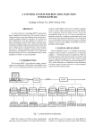
1
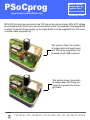
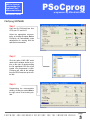
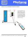
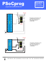
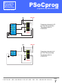
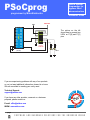
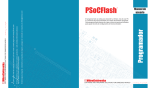
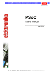
PSoCprog
USB In System
Programmer for
Cypress PSoC
microcontrollers
programmer by MikroElektronika
Quickstart Guide
ABOUT PSoCprog PROGRAMMER
With complementary software, PSoCprog programmer represents a great tool for all those
working with Cypress’s microcontrollers. The microcontroller connects to the PSoCprog programmer via 6 lines, three of which are VCC, MCU-VCC and GND and others are PGC,
PGD and RST. Unlike programmers whose operation is based on bootloads (and which
need to give away part of their memory to a bootload program) PSoCprog programs the
microcontroller externally so that the entire memory is available for the programmer. To use
the benifits of In-System Programming, target board must have IDC10 connector with following pinout:
VCC
GND
GND
MCU-VCC
RST
GND
P1[1] (PGC)
GND
P1[0] (PGD)
PGC and PGD pins connects to the microcontrollers SCL and SDA pins, respectively. SCL
and SDA are standard pins for I2C communication (SCL - serial clock, SDA - serial data).
I2C communication lines on the target board must be connected directly to the connector.
page
SOFTWARE AND HARDWARE SOLUTIONS FOR THE EMBEDDED WORLD
1
PSoCprog
programmer by MikroElektronika
USB In System
Programmer for
Cypress PSoC
microcontrollers
Quickstart Guide
MCU-VCC pin must be connected to the VCC pin on the microcontroller. MCU-VCC voltage
is controlled by the PSoCprog so the microcontroller mustn’t be powered by the target board
in which it’s placed! Power supply on the target board must be separated from the microcontroller while programming!
This picture shows the position
of jumper when the target board
and PSoCprog programmer are
powered trough USB connector.
This picture shows the position
of jumper when PSoCprog programmer is powered by the target board.
page
2
SOFTWARE AND HARDWARE SOLUTIONS FOR THE EMBEDDED WORLD
USB In System
Programmer for
Cypress PSoC
microcontrollers
Quickstart Guide
PSoCprog
programmer by MikroElektronika
PSoCprog SOFTWARE
Step 1
Copy the file PSoCprog2.exe from
CD to your PC, and run it.
Select the appropriate microcontroller, by clicking the option Device.
PSoCprog will automatically make
adjustments for working with the
specified microcontroller.
Step 2
Click the option LOAD HEX which
opens up the window similar to picture on the right. By double-clicking
the file, appropriate HEX file will be
loaded into programmer’s buffer.
PSoCprog will read all the settings
from the HEX file and set up the control bits.
Step 3
Programming the microcontroller
starts by clicking the option Write in
the right corner of the working window.
page
SOFTWARE AND HARDWARE SOLUTIONS FOR THE EMBEDDED WORLD
3
PSoCprog
programmer by MikroElektronika
USB In System
Programmer for
Cypress PSoC
microcontrollers
Quickstart Guide
KEYBOARD SHORTCUTS AND COMMAND LINE PARAMETERS.
Keyboard
Shortcuts
Alt-E
Alt-W
Alt-V
Alt-R
Alt-D
Ctrl-S
Ctrl-O
Ctrl-R
Command
Line
Alternatively, you can use the PSoCprog programmer from the command
line. It will allow you to use PSoCprog from some other software, compiler
etc. The command line parameters are:
Examples
Erase
Write
Verify
Read
Change MCU
Save
Open (Load)
Reload
-w
-v
-r
-e
-p
-f
Write to PSoC
Verify
Read from PSoC
Erase PSoC
PSoC name (for example CY8C27643, CY8C26443...)
Filename (use " as delimiters)
1.
psocprog2.exe -w -pCY8C27643 -v -f"C:\somefile.hex"
This will program the PSoC using C:\somefile.hex and it will verify
the write
2.
psocprog2.exe -r -pCY8C27643
This will read the PSoC contents into on screen buffer
3.
psocprog2.exe -e -pCY8C27643
This will erase the PSoC
page
4
SOFTWARE AND HARDWARE SOLUTIONS FOR THE EMBEDDED WORLD
PSoCprog
USB In System
Programmer for
Cypress PSoC
microcontrollers
programmer by MikroElektronika
Quickstart Guide
EXTERNAL PSoCprog PROGRAMMER CONNECTION SCHEMATICS
MCU-VCC
VCC
P3[3]
P3[1]
SMP
P4[7]
P4[5]
P4[3]
P4[1]
P5[3]
P5[1]
P1[7]
P1[5]
P1[3]
P1[1]
VSS
VCC
P0[6]
P0[4]
P0[2]
P0[0]
P2[6]
P2[4]
P2[2]
PSoC
P0[7]
P0[5]
P0[3]
P0[1]
P2[7]
P2[5]
P2[3]
P2[1]
P3[7]
P3[5]
P2[0]
P3[6]
P3[4]
P3[2]
P3[0]
Xres
P4[6]
P4[4]
P4[2]
P4[0]
P5[2]
P5[0]
P1[6]
P1[4]
P1[2]
P1[0]
VCC
GND
GND
MCU-VCC
RST
GND
P1[1] (PGC)
GND
P1[0] (PGD)
PSoCprog
CONNECTOR
One of the possibilities for connecting PSoCprog to a microcontroller is by using an IDC10
connector as shown on the picture on the left. All you have to
do is to put one 2x5 connector
on the target board connected
as shown on the sheme. Once
you plug in the PSoCprog connector you will be able to program PSoC In System.
48 PIN
page
SOFTWARE AND HARDWARE SOLUTIONS FOR THE EMBEDDED WORLD
5
PSoCprog
programmer by MikroElektronika
USB In System
Programmer for
Cypress PSoC
microcontrollers
Quickstart Guide
MCU-VCC
VCC
P3[3]
P3[1]
SMP
P4[7]
P4[5]
P4[3]
P4[1]
P5[3]
P5[1]
P1[7]
P1[5]
P1[3]
P1[1]
VSS
VCC
P0[6]
P0[4]
P0[2]
P0[0]
P2[6]
P2[4]
P2[2]
PSoC
P0[7]
P0[5]
P0[3]
P0[1]
P2[7]
P2[5]
P2[3]
P2[1]
P3[7]
P3[5]
VCC
GND
GND
MCU-VCC
RST
P2[0]
P3[6]
P3[4]
P3[2]
P3[0]
Xres
P4[6]
P4[4]
P4[2]
P4[0]
P5[2]
P5[0]
P1[6]
P1[4]
P1[2]
P1[0]
GND
P1[1] (PGC)
GND
P1[0] (PGD)
Connection schematic for 48
pin PSoC Microcontrollers.
The scheme aplies to:
CY8C27643...
PSoCprog
CONNECTOR
48 PIN
MCU-VCC
VCC
VCC
P0[6]
P0[4]
P0[2]
P0[0]
P2[6]
P2[4]
P2[2]
PSoC
P0[7]
P0[5]
P0[3]
P0[1]
P2[7]
P2[5]
P2[3]
P2[1]
SMP
P1[7]
P1[5]
P1[3]
P1[1]
VSS
P2[0]
Xres
P1[6]
P1[4]
P1[2]
P1[0]
VCC
GND
GND
MCU-VCC
RST
GND
P1[1] (PGC)
GND
P1[0] (PGD)
Connection schematic for 28
pin PSoC Microcontrollers.
The scheme aplies to:
CY8C26443...
PSoCprog
CONNECTOR
28 PIN
page
6
SOFTWARE AND HARDWARE SOLUTIONS FOR THE EMBEDDED WORLD
PSoCprog
USB In System
Programmer for
Cypress PSoC
microcontrollers
programmer by MikroElektronika
Quickstart Guide
MCU-VCC
VCC
VCC
P0[6]
P0[4]
P0[2]
P0[0]
Xres
P1[6]
P1[4]
P1[2]
P1[0]
VCC
GND
GND
MCU-VCC
RST
PSoC
P0[7]
P0[5]
P0[3]
P0[1]
SMP
P1[7]
P1[5]
P1[3]
P1[1]
VSS
GND
P1[1] (PGC)
GND
P1[0] (PGD)
Connection schematic for 20
pin PSoC Microcontrollers.
The scheme aplies to:
CY8C26233...
PSoCprog
CONNECTOR
20 PIN
MCU-VCC
VCC
VCC
PSoC
P0[7]
P0[5]
P1[1]
VSS
P0[4]
P0[2]
P1[0]
8 PIN
VCC
GND
GND
MCU-VCC
GND
P1[1] (PGC)
GND
P1[0] (PGD)
Connection schematic for 8
pin PSoC Microcontrollers.
The scheme aplies to:
CY8C25122...
PSoCprog
CONNECTOR
page
SOFTWARE AND HARDWARE SOLUTIONS FOR THE EMBEDDED WORLD
7
PSoCprog
USB In System
Programmer for
Cypress PSoC
microcontrollers
programmer by MikroElektronika
Quickstart Guide
MCU-VCC
VCC
VCC
P0[6]
P0[4]
P0[2]
P0[0]
P2[6]
P2[4]
P2[2]
PSoC
P0[7]
P0[5]
P0[3]
P0[1]
P2[7]
P2[5]
P2[3]
P2[1]
SMP
P1[7]
P1[5]
P1[3]
P1[1]
VSS
P2[0]
Xres
P1[6]
P1[4]
P1[2]
P1[0]
VCC
GND
GND
MCU-VCC
The picture on the left
shows how to connect two
LED’s on P1[0] and P1[1]
pins.
RST
GND
P1[1] (PGC)
GND
P1[0] (PGD)
PSoCprog
CONNECTOR
CY8C26443
(28 PIN)
1K
1K
LED’s
If you are experiencing problems with any of our products
or you just want additional information, please let us know.
We are committed to meeting your every need.
AR
M
S
2
OL
PI
51
80
C OM
68HC08
USB
programmer
O
C
ng
akaisy
Mit e
D EV
.T
PI
E-mail: [email protected]
WWW: www.mikroe.com
BO
AVR
oC
USB
S
PS
If you have any other question, comment or a business
proposal, please contact us:
R
LE
KS
O
Technical Support :
[email protected]
page
8
SOFTWARE AND HARDWARE SOLUTIONS FOR THE EMBEDDED WORLD