1
All MikroElektronika´s development systems represent irreplaceable tools for
programming and developing microcontroller-based devices. Carefully chosen
components and the use of machines of the last generation for mounting and
testing thereof are the best guarantee of high reliability of our devices. Due to
simple design, a large number of add-on modules and ready to use examples,
all our users, regardless of their experience, have the possibility to develop
their project in a fast and efficient way.
User manual
Development System
UNI-DS3
3
™
TO OUR VALUED CUSTOMERS
I want to express my thanks to you for being interested in our products and for having confidence in
mikroElektronika.
The primary aim of our company is to design and produce high quality electronic products and to constantly
improve the performance thereof in order to better suit your needs.
Nebojša Matiü
General Manager
The Atmel name and logo, the Atmel logo, AVR, AVR (Logo), AVR Freaks, AVR Freaks (Logo), AVR Studio, IDIC, megaAVR, megaAVR
(Logo), picoPower ®, tinyAVR ® are trademarks of Atmel Coorporation.
The Microchip name and logo, the Microchip logo, Accuron, dsPIC, KeeLoq, microID, MPLAB, PIC, PICmicro, PICSTART, PRO MATE,
PowerSmart, rfPIC and SmartShunt are registered trademarks of Microchip Technology Incorporated in the U.S.A and other countries.
3
page
UNI-DS3 Development System
TABLE OF CONTENTS
Introduction to UNI-DS3 Development System ................................................................................ 4
Key Features ..................................................................................................................................... 5
1.0. Connecting the System to a PC ................................................................................................ 6
2.0. Placing MCU Card ..................................................................................................................... 7
3.0. Power Supply ............................................................................................................................. 8
4.0. USB Connector for MCU Programmer ...................................................................................... 9
5.0 USB Communication Module ..................................................................................................... 9
6.0 CAN Communication Module .................................................................................................... 10
7.0. RS232 Communication Module ................................................................................................ 11
8.0. RS485 Communication Module ................................................................................................. 12
9.0. MMC/SD Connector .................................................................................................................. 13
10.0. Real-Time Clock (RTC) ........................................................................................................... 14
11.0. Digital-to-Analog Converter (DAC) ...........................................................................................15
12.0. A/D Converter Test Inputs .......................................................................................................16
13.0. Ethernet Module ..................................................................................................................... 17
14.0. LEDs ....................................................................................................................................... 18
15.0. Push Buttons .......................................................................................................................... 19
16.0. 2x16 LCD Display ................................................................................................................... 20
17.0. 128x64 Graphic LCD Display ................................................................................................. 21
18.0. I/O Ports .................................................................................................................................. 22
19.0. MCU Card with 8051 Microcontroller ...................................................................................... 24
20.0. MCU Card with AVR Microcontroller ....................................................................................... 26
21.0. MCU Card with dsPIC Microcontroller .................................................................................... 28
22.0. MCU Card with PIC Microcontroller in DIP40 Package .......................................................... 30
23.0. MCU Card with PIC Microcontroller in TQFP80 Package ....................................................... 32
24.0. MCU Card with PSoC Microcontroller ..................................................................................... 34
25.0. MCU Card with ARM Microcontroller ...................................................................................... 36
MikroElektronika
page
4
UNI-DS3 Development System
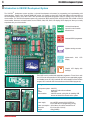
Introduction to UNI-DS3 Development System
The UNI-DS3™ development system provides a universal development environment for programming and experimenting with
microcontrollers. Thanks to the universal DIMM-168P socket, it is possible to place MCU cards with different microcontrollers on
this development system. Every MCU card is also provided with appropriate programmer used for loading a hex code into the
microcontroller. The UNI-DS3 development system may come with an MCU card with PIC®, dsPIC®, AVR®, 8051, ARM® or PSoC®
microcontroller. Numerous on-board modules, such as RS232, CAN, ADC, DAC, LCD display, GLCD display etc. allow you to easily
experiment with your microcontroller.
Universal development
system for microcontroller
based devices
On-board USB 2.0 programmer
Digital-to-analog converter
Alphanumeric
display
2x16
LCD
Graphic LCD display with
backlight
Every MCU card is provided with appropriate programmer. To load a hex code
from a PC to the microcontroller it is also necessary to have appropriate program
for it installed on the PC. MCU cards with PIC microcontrollers use the 3,&ÀDVK
program, MCU cards with AVR microcontrollers use the $95ÀDVK program etc.
3DFNDJHFRQWDLQV
Development system:
CD:
Cables:
Documentation:
UNI-DS3
product CD with relevant software
USB cable
UNI-DS3 manual, quick guide for installing USB
drivers and electrical schematic of the system
6\VWHPVSHFL¿FDWLRQ
Power supply:
over a AC/DC connector (8-16V AC/DC); or
over a USB cable for programming (5V DC)
Power consumption: ~20mA when all on-board modules are off
Dimension:
25 x 21cm (9,8 x 8,2inch)
Weight:
~400g (0.88lbs)
MikroElektronika
5
1
2
3
4
5
6
7
8
9
page
UNI-DS3 Development System
10
11
26
12
25
13
24
14
23
22
15
21
20
16
19
17
18
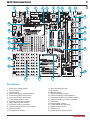
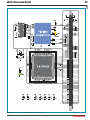
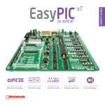
.H\)HDWXUHV
1. Power supply voltage regulator
2. Ethernet connector
3. Ethernet module
4. Alphanumeric display contrast adjustment
5. Connector for RS485 communication
6. Connector for RS232 communication
7. 4.096V voltage reference source
8. Connector for CAN communication
9. MCU programmer USB connector
10. Connector for USB communication
11. Jumper for pull-up/pull-down resistor selection
12. I/O port connectors
13. Pull-up/pull-down resistors
14.
15.
16.
17.
18.
19.
20.
21.
22.
23.
24.
25.
26.
Socket for placing MCU card
DIP switches
MMC/SD card slot
Graphic LCD display connector
Graphic LCD display contrast adjustment
Push buttons simulate microcontroller input pins
Jumper for selecting push buttons’ logic state
Reset button
Analog-to-digital converter
72 LEDs indicate pins’ logic state
Digital-to-analog converter
Real-time clock
Alphanumeric LCD display connector
MikroElektronika
page
6
UNI-DS3 Development System
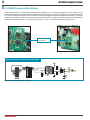
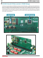
&RQQHFWLQJWKH6\VWHPWRD3&
6WHS
Prior to connecting the development system to a PC, it is necessary to install the appropriate USB driver essential for the proper
operation of the programmer. In addition to the USB driver, it is also necessary to install the appropriate program for loading a
.hex code into the microcontroller. Instructions for installing USB drivers are provided in the relevant manual accompanying the
development system (Quick guide for installing USB drivers).
6WHS
MCU card with the microcontroller must be placed into the DIMM-168P socket prior to connecting the development system to a PC.
6WHS
Use the USB cable to connect the UNI-DS3 development system to a PC. One end of the USB cable, with a USB connector of B type,
should be connected to the development system, as shown in Figure 1-2, whereas the other end of the cable with a USB connector
of A type should be connected to the PC. When establishing a connection, make sure that jumper J11 is placed in the USB position
as shown in Figure 1-1.
AC/DC connector
USB connector
1
2
Jumper J11 for selecting
power supply source
POWER SUPPLY
switch
)LJXUHPower supply
)LJXUH Connecting USB cable
6WHS
Turn on your development system by setting the POWER SUPPLY switch to the ON position. An LED diode marked as POWER will
be automatically turned on indicating that your development system is ready to use.
127( If some additional modules are used, such as LCD, GLCD etc, it is necessary to place them properly on the development
system while it is turned off. Otherwise, either can be permanently damaged. Refer to Figure below for the proper placing of
the additional modules.
)LJXUHPlacing additional modules on the development system
MikroElektronika
7
page
UNI-DS3 Development System
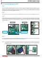
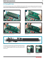
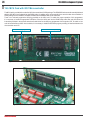
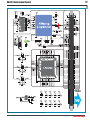
3ODFLQJ0&8&DUG
The UNI-DS3 development system provides a DIMM-168P socket to place an MCU card into. All MCU cards are placed in the same
PDQQHU,WLVVKRZQLQ¿JXUHVEHORZKRZWRSODFHWKHUNI-DS3 card with a PIC microcontroller in TQFP80 package. Any card intended
to be used on the UNI-DS3 development system may be placed instead of this one.
1
2
A
B
Open extraction levers A and B
3
Push the MCU card down gently into the DIMM-168P socket and
lift extraction levers slowly at the same time
Place the MCU card into the DIMM-168P socket
4
Close the extraction levers when the MCU card is properly placed
into the socket
)LJXUH: Schematic of the DIMM-168P socket’s pinout
The UNI-DS3 development system may be delivered with MCU cards with
one of the following microcontroller families: PIC, dsPIC, AVR, 8051, ARM
and PSoC. Detailed descriptions of MCU cards are provided at the end
of this manual.
Extraction lever used
WR ¿[ 0&8 FDUG LQ WKH
‘open’ position
Extraction lever used
WR ¿[ 0&8 FDUG LQ WKH
‘closed’ position
MikroElektronika
page
8
UNI-DS3 Development System
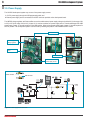
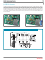
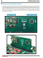
3.0. Power Supply
The UNI-DS3 development system may use one of two power supply sources:
1. +5V PC power supply through the USB programming cable; and
2. External power supply source connected to an AC/DC connector provided on the development board.
7KH/0YROWDJHUHJXODWRUDQG*UHW]UHFWL¿HUDUHXVHGWRHQDEOHH[WHUQDOSRZHUVXSSO\YROWDJHWREHHLWKHU$&LQWKHUDQJHRI9
to 16V) or DC (in the range of 8V to 16V). Jumper J11 is used as a selector for a power supply source. To make advantage of the USB
power supply, jumper J11 should be placed in the USB position. When using external power supply, jumper J11 should be placed in
the EXT position. The development system is turned on/off by switching the position of the POWER SUPPLY switch.
AC/DC connector
Power supply
voltage regulator
POWER SUPPLY
switch
USB connector
J11 as a selector for a
power supply source
)LJXUH: Power supply
AC/DC connector
USB connector
)LJXUH: Power supply source schematic
MikroElektronika
9
page
UNI-DS3 Development System
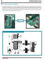
0&83URJUDPPHU USB Connector
The USB connector (CN15) provided on the UNI-DS3 development system is connected to the on-board programmer on the MCU
card. Every MCU card is supplied with a built-in programmer matching the relevant microcontroller. For example, the MCU card with
a PIC microcontroller is supplied with the built-in 3,&ÀDVK programmer with mikroICD support. To load a .hex code from a PC into the
microcontroller it is necessary to install the program providing an interface between the PC and built-in programmer. For the MCU card
with a PIC microcontroller, it is the 3,&ÀDVK program to be installed. In case an MCU card with some other type of the microcontroller
is used then it is necessary to install the appropriate program depending on the microcontroller in use.
)LJXUH: USB connector for
MCU programmer
)LJXUH: USB connector CN15 schematic
86%&RPPXQLFDWLRQ0RGXOH
The USB connector CN21 enables connection between the MCU card, provided with the microcontroller with the USB communication
module, and external device. The MCU card is connected to the USB connector CN21 through MCU-USBDN and MCU-USBDP
communication lines. The MCU-VBUS line is used to detect external USB device connected to the development system.
)LJXUH: USB connector for USB
communication
)LJXUH: USB connector CN21 schematic
MikroElektronika
page
10
UNI-DS3 Development System
6.0. &$1&RPPXQLFDWLRQ0RGXOH
CAN (Controller Area Network) is a communication standard primarily intended for use in automotive industry. It enables the
microcontroller to communicate to a car device without using a host PC. In addition, such communication is widely used in industrial
automation. The MCP2551 circuit is used for communication between the CAN controller (MCP2510) and the taget device. The
MCP2510 circuit is a stand-alone CAN controller which communicates to the microcontroller using SPI communication. To enable
connection between the microcontroller and MCP2510, it is necessary to set switches 6, 7 and 8 on the DIP switch SW2 as well as
switches 4, 5 and 6 on the DIP switch SW4 to the ON position.
Connection for CAN
communication
)LJXUH: CAN module
&$1FRPPXQLFDWLRQLVHQDEOHGYLD',3VZLWFKHV6:DQG6:
)LJXUH: CAN communication module connection schematic
MikroElektronika
)LJXUH: CAN module connector
11
page
UNI-DS3 Development System
56&RPPXQLFDWLRQ0RGXOH
USART (8QLYHUVDO6\QFKURQRXV$V\QFKURQRXV5HFHLYHU7UDQVPLWWHU) is one of the most common ways of exchanging data between
the PC and peripheral units. The RS232 serial communication is performed through a 9-pin SUB-D connector and the microcontroller
USART module. The UNI-DS3 provides one RS232A port. Use switches marked as RX232A and TX232A as well as RX232B and
TX232B on the DIP switch SW3 to enable port RS232A. The microcontroller pins used in such communication are marked as follows:
RX - UHFHLYHGDWDOLQH and TX -WUDQVPLWGDWDOLQH. Data rate goes up to 115 kbps.
In order to enable the microcontroller’s USART module to receive input signals which meet the RS232 standard, it is necessary to
adjust voltage levels using an IC circuit such as MAX232.
RS232 connector
)LJXUH: RS232 module connector
)LJXUH: RS232 module
3RUW56$LVFRQQHFWHGWRWKHPLFURFRQWUROOHU
As mentioned above, the UNI-DS3 development system is a
universal tool which makes it suitable for use with different
microcontrollers. The position of pins used for RS232
communication is not the same for all microcontrollers. In
order to enable different microcontrollers to make advantage
of RS232 communication it is necessary to select appropriate
microcontroller pins to be used for such communication. DIP
switch SW3 is used as a communication line selector.
The method of connecting the RS232 communication module
depends on the MCU card placed into the DIMM-168P socket.
All MCU cards are described at the end of this manual and it is
clearly stated which pins are used for RS232 communication
with microcontrollers. For example, for the 8051 MCU card,
switches 5 (RX232A) and 6 (TX232A) on the DIP switch
SW3 are used. For the ATmega128 MCU card, switches 5,
6, 7 and 8 on the DIP switch SW3 may be used. Which of
these four pins are to be used here depends on which pins
on the ATmega128 microcontroller you want to use for RS232
communication. In case pins RE0 and RE1 are used, switches
5 (RX232A) and 6 (TX232A) on the DIP switch SW3 should be
set to the ON position. In case pins RD2 and RD3 are used,
switches 7 (RX232B) and 8 (TX232B) on the DIP switch SW3
should be set to the ON position.
)LJXUH: RS232 module and microcontroller connection schematic
MikroElektronika
page
12
UNI-DS3 Development System
56&RPPXQLFDWLRQ0RGXOH
RS485 communication is a communication standard primerily intended for use in industrial applications. The main features of this
communication standard is the ability to exchange data between distant points (up to 1200 m) and high tolerance to accompanying noise.
The UNI-DS3 development system features a connector used for connecting devices which use RS485 communication. The LTC485
circuit acts as a transciever between an external device and the microcontroller. To enable connection between the microcontroller and
the RS485 communication module, it is necessary to set switches 1, 2 and 3 on the DIP switch SW4 to the ON position.
Connector for RS485
communication
)LJXUH: RS485 module
56FRPPXQLFDWLRQLVHQDEOHGYLD',3VZLWFK6:
)LJXUH: RS485 module connection schematic
MikroElektronika
)LJXUH: RS485 module connector
13
page
UNI-DS3 Development System
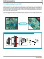
9.0. 00&6'&RQQHFWRU
The MMC/SD connector is used to enable memory cards to be interfaced with the microcontroller. To enable communication between
memory card and microcontroller, it is necessary to adjust their voltage levels. Memory card is powered by the 3.3V power supply
voltage (VCC3) generated by the REG2 voltage regulator, whereas the microcontroller’s power supply voltage is 5V (VCC). In case
the MCU card is powered with 5V power supply voltage, it is necessary to remove jumpers J17, J18 and J19. As a result, resistors
start acting as a voltage dividers. In this case, such divider is used to lower the microcontroller’s power supply voltage from 5V to
3.3V. To enable communication between microcontroller and memory card, switches 4, 5 and 6 on the DIP switch SW4 should be
set to the ON position.
)LJXUH: MMC/SD connector
)LJXUH: MMC/SD memory card
7RXVH0&8FDUGVUHTXLULQJ9SRZHUVXSSO\YROWDJHLWLVQHFHVVDU\WRUHPRYHMXPSHUV--DQG-
)LJXUH: MMC/SD connector connection schematic
MikroElektronika
page
14
UNI-DS3 Development System
5HDO7LPH&ORFN57&
A real-time clock is widely used in alarm devices, industrial controllers, consumer devices etc. Thanks to the PCF8583 circuit, the UNIDS3 development system is capable of keeping the real time. The main features of the real-time clock are as follows:
- clock with calendar
- I2C serial interface
- universal counter used as an alarm
- ability to change the time format (12/24h)
The real-time clock provided on the UNI-DS3 development system is used to generate an interrupt at pre-set time. In order to establish
connection between the microcontroller and real-time clock it is necessary to set switch 1 on the DIP switch SW3, as well as switches
7 and 8 on the DIP switch SW4 to the ON position.
3V battery enables the operation
of the real-time clock when the
power supply is off
Quartz-crystal provides
accuracy of the clock signal
used by the real-time clock
)LJXUH: Real-time clock
5HDOWLPHFORFNLVFRQQHFWHGWRWKHPLFURFRQWUROOHUYLD',3VZLWFKHV6:DQG6:
)LJXUH: Real-time clock and microcontroller connection schematic
MikroElektronika
15
page
UNI-DS3 Development System
'LJLWDOWR$QDORJ&RQYHUWHU'$&
A digital-to-analog converter is a module used to convert a digital code into an analog voltage signal. The UNI-DS3 development
system is equipped with the MCP4921 circuit which acts as a 12-bit digital-to-analog converter. This circuit provides a high accuracy
of conversion as well as a high-quality signal despite noises occuring when it is used in industrial applications. It communicates with
the microcontroller via SPI serial communication. In order to establish connection between these two circuits, it is necessary to set
switches 3 and 4 on the DIP switch SW3 to the ON position. It is also necessary to enable serial communication by setting switches 4
and 6 on the DIP switch SW4 to the ON position.
The function of jumper J15 is to determine voltage reference to be used in digital-to-analog conversion. By setting jumper to the 4.096
position, the MCP4921 circuit will be powered with the 4.096V voltage. By setting jumper J15 to the VCC position, the MCP4921 circuit
will be powered with the 5V power supply voltage.
Connector for digitalto-analog converter
)LJXUH: DAC module
)LJXUH: DAC connector
'LJLWDOWRDQDORJFRQYHUWHULVFRQQHFWHGWRWKHPLFURFRQWUROOHUYLD',3VZLWFKHV6:DQG6:
)LJXUH: DAC module connection schematic
MikroElektronika
page
16
UNI-DS3 Development System
12.0. $'&RQYHUWHU7HVW,QSXWV
An A/D converter is used for converting an analog signal into the appropriate digital value. A/D converter is linear, which means that
converted number is linearly dependent on the input voltage value. The MCP3204 circuit is used as an A/D converter on the UNI-DS3
development system. Voltage to be converted is brought to the A/D converter input pins which converts it into a 12-bit number. The
result of conversion is transferred to the microcontroller by means of serial communication. To make this transmission possible, it is
necessary to set switch 2 on the DIP switch SW3 as well as switches 4, 5 and 6 on the DIP switch SW4 to the ON position.
A voltage reference supplied on the Vref pin of the MCP3204 circuit is used to determine maximum input analog signal, whereas jumper
J15 is used to determine this voltage reference. When jumper J15 is in the 4.096 position, the 4.096V voltage is used as a voltage
reference. Otherwise, when jumper J15 is in the VCC position, then the 5V power supply voltage is used as a voltage reference.
ADC connector
)LJXUH: ADC module
)LJXUH: ADC connector
$'FRQYHUWHULVFRQQHFWHGWRWKHPLFURFRQWUROOHUYLD',3VZLWFKHV6:DQG6:
)LJXUH: ADC module connection schematic
MikroElektronika
17
page
UNI-DS3 Development System
(WKHUQHW0RGXOH
The UNI-DS3 development system is provided with an ethernet module. Its function is to provide an interface between the microcontroller
and LAN (local area network). A stand-alone controller ENC28J60 enables ethernet communication on the development system.
This circuit is used to transfer data from LAN to the microcontroller using serial communication.The 3.3V voltage is required for
the operation of this circuit. To enable data to be transferred to the microcontroller powered with the 5V power supply voltage, it is
necessary to adjust these voltage levels by means of the 74HCT245 transciever. Jumpers J12, J13 and J14 are used for selecting
voltage levels. In case that MCU card with the microcontroller requiring the 5V power supply for its operation is used, it is necessary
to set jumpers J12, J13 and J14 to the 5V position. In case the microcontroller requiring the 3.3V power supply for its operation is
used, it is necessary to set jumpers J12, J13 and J14 to the 3.3V position. To enable connection between the ethernet module and
the microcontroller, switches 2, 3, 4 and 5 on the DIP switch SW2, as well as switches 4, 5 and 6 on the DIP switch SW4 must be set
to the ON position.
Ethernet module connector
)LJXUH: Ethernet connector
)LJXUH: Ethernet module
(WKHUQHWPRGXOHLVFRQQHFWHGWRWKHPLFURFRQWUROOHUYLD',3VZLWFKHV6:DQG6:
)LJXUH: Ethernet module connection schematic
MikroElektronika
page
18
UNI-DS3 Development System
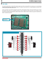
14.0. LEDs
/('/LJKW(PLWWLQJ'LRGHLVDKLJKO\HI¿FLHQWHOHFWURQLFOLJKWVRXUFH:KHQFRQQHFWLQJ/('VLWLVQHFHVVDU\WRXVHDFXUUHQWOLPLWLQJ
resistor. A common LED diode voltage is approximately 2.5V, while the current varies from 1 to 20mA depending on the type of LED.
The UNI-DS3 uses LEDs with current I=1mA.
There are 72 LEDs on the UNI-DS3 development system which visually indicate the state of each microcontroller I/O pin. An active
LED indicates that a logic one (1) is present on the pin. In order to enable the pin state to be shown, it is necessary to select
appropriate port (PORTA, PORTB, PORTC, PORTD, PORTE, PORTF, PORTG, PORTH or PORTJ) using the DIP switch SW1 and
switch 1 on the DIP switch SW2.
Resistor network used to
OLPLWFXUUHQWÀRZ
)LJXUH: LEDs
/('VRQSRUWV3257%DQG3257&DUHWXUQHGRQ
)LJXUH: LEDs and ports PORTB and PORTC connection schematic
MikroElektronika
19
page
UNI-DS3 Development System
3XVKEXWWRQV
The logic state of all microcontroller input pins may be changed by means of push buttons. Jumper J10 is used to determine the
logic state to be applied to the desired microcontroller pin by pressing appropriate push button. Right next to the push buttons,
there is a RESET button which is used to provide the MCLR pin with the microcontroller reset signal over the programmer provided
on the MCU card.
RESET button
Jumper J10 used for selecting
logic state to be applied to the
pin by pressing push button
Push buttons used for simulating
digital inputs
)LJXUH: Push buttons
In Figure 15-2, jumper J10 is in the VCC position. In this case, by pressing any push button, a logic one (5V) will be applied to the
appropriate microcontroller pin.
3UHVVXUHRQDQ\SXVKEXWWRQZLOOFDXVHWKHPLFURFRQWUROOHUSLQWREHGULYHQKLJK
)LJXUH: Push-buttons and port PORTB connection schematic
MikroElektronika
page
20
UNI-DS3 Development System
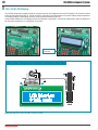
16.0. 2x16/&''LVSOD\
The UNI-DS3 development system provides an on-board connector for the alphanumeric 2x16 LCD display. This connector is linked
to the microcontroller via pins D0, D1, D4, D5, D6 and D7 on the MCU card. Potentiometer P2 is used for display contrast adjustment.
The display backlight is automatically turned on by turning the development system on.
Communication between the LCD display and the microcontroller is performed in a 4-bit mode. Alphanumeric digits are displayed in
two lines each containing up to 16 characters of 7x5 pixels.
Contrast adjustment
potentiometer
)LJXUH: Alphanumeric LCD display connector
)LJXUH: Alphanumeric 2x16 LCD display
/&'GLVSOD\EDFNOLJKWLVDXWRPDWLFDOO\WXUQHGRQDORQJZLWKWKHGHYHORSPHQWV\VWHP
)LJXUHAlphanumeric 2x16 LCD display connection schematic
MikroElektronika
21
page
UNI-DS3 Development System
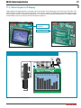
17.0. 128x64 *UDSKLF/&''LVSOD\
128x64 graphic LCD display (GLCD) is connected to the microcontroller via the following pins on the MCU card: LCD-CS1#, LCDCS2#, LCD-RS, LCD-RW, LCD-E, LCD-RST and D0-D7. It has a screen resolution of 128x64 pixels, which allows diagrams, tables
and other graphic content to be displayed. Potentiometer P1 is used for the GLCD display contrast adjustment. The display backlight
is automatically turned on by turning the UNI-DS3 development system on.
Contrast adjustment
potentiometer
GLCD display connector
)LJXUH: GLCD display
)LJXUH: GLCD connector
*/&'GLVSOD\EDFNOLJKWLVDXWRPDWLFDOO\WXUQHGRQDORQJZLWKWKHGHYHORSPHQWV\VWHP
)LJXUH: GLCD display connection schematic
MikroElektronika
page
22
UNI-DS3 Development System
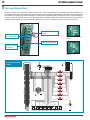
18.0. ,QSXW2XWSXW3RUWV
Along the right side of the development system, there are nine 10-pin connectors which are connected to the microcontroller’s I/O
ports. Microcontroller pins used for programming are not directly connected to the appropriate 10-pin connectors, but via a multiplexer.
The multiplexer is provided on the MCU card and is connected to the programmer. Microcontroller pins can be connected to pull-up/
pull-down resistors by means of jumpers J1-J9. All pull-up/pull-down resistors together form a resistor network which can be removed
and replaced with another one. If pull-up/pull-down resistors are not used, it is necessary to remove them or jumpers (J0-J9).
Additional module connected
to PORTC
Jumper for pull-up/pulldown resistor selection
)LJXUH J3 in pull-down
position
PORTF 2x5 male connector
Resistor network may be
removed and replaced
with another one
)LJXUH: I/O ports
3RUW3257%SLQVDUH
connected to pull-down
resistors
)LJXUH: Port PORTB connection schematic
MikroElektronika
)LJXUH J3 in pull-up
position
23
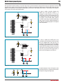
Pull-up/pull-down resistors enable you to set the logic level on all microcontroller’s input pins when they are in idle state. Such level
depends on the position of the pull-up/pull-down jumper. The RB1 microcontroller pin with jumper J2 and the RB1 push button with
jumper J10 are used here for the purpose of explaining the performance of pull-up/pull-down resistors. The principle of their operation
is the same as for all other microcontroller pins.
In order to enable connection between the
PORTB port and pull-down resistors, it is
necessary to place jumper J2 in the Down
SRVLWLRQ¿UVW,QWKLVZD\DQ\3257%SRUWSLQFDQ
be supplied with a logic zero (0V) in idle state
over jumper J2 and 8x100K resistor network.
As a result, every time you press the RB1 push
button, a logic one (VCC voltage) will appear on
the RB1 pin, provided that jumper J10 is placed
in the VCC position.
)LJXUH: Jumper J2 in pull-down and jumper J10 in pull-up position
In order to enable port PORTB pins to be
connected to pull-up resistors and the port input
pins to be supplied with a logic zero (0), it is
necessary to place jumper J2 in the Up position
and jumper J10 in the GND position. This enables
any port PORTB input pin to be driven high (5V)
in idle state over the 100K resistor. As a result,
every time you press the RB1 push button, a
logic zero (0V) will appear on the RB1 pin.
)LJXUH Jumper J2 in pull-up and jumper J10 in pull-down position
In case that jumpers J2 and J10 have the same
logic state, pressure on any button will not cause
input pins to change their logic state.
)LJXUH Jumpers J2 and J10 in the same position
MikroElektronika
page
UNI-DS3 Development System
page
24
UNI-DS3 Development System
0&8&DUGZLWK0LFURFRQWUROOHU
The MCU card is provided with a socket for 8051 microcontrollers in DIP40 package. The AT89S8253 microcontroller normally delivered
with the 8051 MCU card is placed into the DIP40 socket. In addition to this microcontroller, there are also other microcontrollers in
DIP40 package such as AT89S51, AT89S52, AT89S53 and AT89S8252 that can be used here.
There is an on-board programmer 8051prog provided on the MCU card. To enable the proper operation of this programmer,
LW LV QHFHVVDU\ WR LQVWDOO WKH DSSURSULDWH 86% GULYHU 3ODFH WKH 0&8 FDUG LQWR WKH ',00S VRFNHW ¿UVW DQG WKHQ IROORZ WKH
instructions provided in the relevant manual and install driver for the 8051prog programmer from the product CD. To enable a .hex
code to be loaded into an 8051 microcontroller, it is necessary to install the ÀDVKprogram providing an interface between the
microcontroller and a PC.
On-board 8051prog programmer
Microcontroller in DIP40 package
)LJXUH: MCU card with an 8051 microcontroller
)LJXUH: 8051 MCU card placed in the DIMM-168p socket
MikroElektronika
25
page
UNI-DS3 Development System
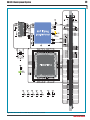
)LJXUH: MCU card with the DIMM-168p socket connection schematic
MikroElektronika
page
26
UNI-DS3 Development System
0&8&DUGZLWK$950LFURFRQWUROOHU
The MCU card is provided with the ATmega128 microcontroller in 64-pin TQFP package. In addition to this microcontroller, there is also
a built-in programmer AVRprog as well as the CN2 connector provided on the MCU card. Such connector is intended for connecting
the external JTAG programmer. To enable the AVRprog programmer to operate properly, it is necessary to install the appropriate
86%GULYHU3ODFHWKH0&8FDUGLQWRWKH',00SVRFNHW¿UVWDQGWKHQIROORZWKHLQVWUXFWLRQVSURYLGHGLQWKHUHOHYDQWPDQXDODQG
install driver for the AVRprog programmer from the product CD. To enable a .hex code to be loaded into an AVR microcontroller, it is
necessary to install the $95ÀDVK program providing an interface between the microcontroller and a PC.
The external JTAG programmer is connected to the microcontroller on the MCU card by means of the 2x5 male connector CN2. When
this programmer is used, the MCU card doesn’t necessarily have to be placed into the DIMM-168p socket on the development system.
In this case, the MCU card is powered by the external JTAG programmer.
Built-in AVRprog programmer
Microcontroller in TQFP64 package
)LJXUH: MCU card with an AVR microcontroller
)LJXUH: AVR MCU card placed into the DIMM-168p socket
MikroElektronika
27
page
UNI-DS3 Development System
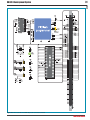
)LJXUH: MCU card with the DIMM-168p socket connection schematic
MikroElektronika
page
28
UNI-DS3 Development System
0&8&DUGZLWKGV3,&0LFURFRQWUROOHU
The MCU card is provided with the dsPIC6014A microcontroller in 80-pin TQFP package. In addition to this microcontroller, there
is also a built-in programmer GV3,&SURJ provided on the MCU card. To enable the GV3,&SURJ programmer to operate properly, it is
QHFHVVDU\WRLQVWDOOWKHDSSURSULDWH86%GULYHU3ODFHWKH0&8FDUGLQWRWKH',00SVRFNHW¿UVWDQGWKHQIROORZWKHLQVWUXFWLRQV
provided in the relevant manual and install driver for theGV3,&SURJ programmer from the product CD. To enable a .hex code to be
loaded into a dsPIC microcontroller, it is necessary to install the GV3,&ÀDVK program. The GV3,&SURJ programmer has a hardware
mikroICD support which enables real-time debugging. As a result, it is possible to monitor variables and state of all registers within the
microcontroller during programming.
Built-in GV3,&SURJprogrammer
)LJXUH: MCU card with a dsPIC the microcontroller
)LJXUH: dsPIC MCU card placed into the DIMM-168p socket
MikroElektronika
Microcontroller in TQFP80 package
29
page
UNI-DS3 Development System
)LJXUH: MCU card with the DIMM-168p socket connection schematic
MikroElektronika
page
30
UNI-DS3 Development System
0&8&DUGZLWK3,&0LFURFRQWUROOHULQ',33DFNDJH
The MCU card is provided with a socket for PIC microcontrollers in DIP40 package. The PIC18F4520 microcontroller normally delivered
with the PIC MCU card is placed into the DIP40 socket. In addition to this microcontroller, there are also other microcontrollers in
DIP40 package such as PIC16F877A, PIC18F4550 etc. that can be used here. There is a built-in programmer 3,&ÀDVK with mikroICD
support provided on the MCU card. To enable the proper operation of this programmer, it is necessary to install the appropriate USB
GULYHU3ODFHWKH0&8FDUGLQWRWKH',00SVRFNHW¿UVWDQGWKHQIROORZWKHLQVWUXFWLRQVSURYLGHGLQWKHUHOHYDQWPDQXDODQGLQVWDOO
driver for the 3,&ÀDVK programmer from the product CD. To enable a .hex code to be loaded into a PIC microcontroller, it is necessary
to install the 3,&ÀDVK program providing an interface between the microcontroller and a PC. The built-in 3,&ÀDVK programmer has a
hardware mikroICD support which enables real-time debugging. As a result, it is possible to monitor variables and state of all registers
within the microcontroller during programming.
A USB communication between the microcontroller and an external USB device is enabled by means of jumpers J1, J2 and J3. In case
the USB communication is not used, it is necessary to set jumpers J1, J2 and J3 to the upper position.
Built-in 3,&ÀDVKprogrammer
)LJXUH: MCU card with a PIC microcontroller
)LJXUH: PIC MCU card placed into the DIMM-168p socket
MikroElektronika
Microcontroller in DIP40 package
31
page
UNI-DS3 Development System
)LJXUH: MCU card with the DIMM-168p socket connection schematic
MikroElektronika
page
32
UNI-DS3 Development System
0&8&DUGZLWK3,&0LFURFRQWUROOHULQ74)33DFNDJH
The MCU card is provided with the PIC18F8520 microcontroller in 80-pin TQFP package. In addition to this microcontroller, there is
also a built-in programmer 3,&ÀDVK with mikroICD support provided on the MCU card. To enable the 3,&ÀDVK programmer to operate
SURSHUO\LWLVQHFHVVDU\WRLQVWDOOWKHDSSURSULDWH86%GULYHU3ODFHWKH0&8FDUGLQWRWKH',00SVRFNHW¿UVWDQGWKHQIROORZ
the instructions provided in the relevant manual and install driver for the 3,&ÀDVK programmer from the product CD. To enable a .hex
code to be loaded into a PIC microcontroller, it is necessary to install the 3,&ÀDVK program. The 3,&ÀDVK programmer has a hardware
mikroICD support which enables real-time debugging. As a result, it is possible to monitor variables and state of all registers within the
microcontroller during programming.
Built-in 3,&ÀDVKprogrammer
)LJXUH: MCU card with a PIC microcontroller
)LJXUH 23-2: PIC MCU card placed into the DIMM-168p socket
MikroElektronika
Microcontroller in TQFP80 package
33
page
UNI-DS3 Development System
)LJXUH: MCU card with the DIMM-168p socket connection schematic
MikroElektronika
page
34
UNI-DS3 Development System
0&8&DUGZLWK36R&0LFURFRQWUROOHU
The MCU card is provided with the CY8C27643 microcontroller in 48-pin SSOP package. In addition to this microcontroller, there
is also a built-in programmer PSoCprog provided on the MCU card. To enable the PSoCprog programmer to operate properly,
LW LV QHFHVVDU\ WR LQVWDOO WKH DSSURSULDWH 86% GULYHU 3ODFH WKH 0&8 FDUG LQWR WKH ',00S VRFNHW ¿UVW DQG WKHQ IROORZ WKH
instructions provided in the relevant manual and install driver for the PSoCprog programmer from the product CD. To enable a .hex
code to be loaded into a PSoC microcontroller, it is necessary to install the36R&ÀDVK program providing an interface between the
microcontroller and a PC.
Built-in PSoCprog programmer
Microcontroller in SSOP package
)LJXUH: MCU card with a PSoC microcontroller
)LJXUH: PSoC MCU card placed into the DIMM-168p socket
MikroElektronika
35
page
UNI-DS3 Development System
)LJXUH: MCU card with the DIMM-168p socket connection schematic
MikroElektronika
page
36
UNI-DS3 Development System
0&8&DUGZLWK$500LFURFRQWUROOHU
The MCU card is provided with the LPC2148 microcontroller in LQFP64 package. In addition to this microcontroller, the MCU card is
also supplied with a battery used to power the microcontroller when the power supply is off. The LPC2148 microcontroller requires 3.3V
generated by the REG1 voltage regulator. In addition to the built-in programmer ARMprog, the microcontroller can be programmed by
means of the external JTAG programmer as well. To enable the ARMprog programmer to operate properly, it is necessary to install
WKH DSSURSULDWH 86% GULYHU 3ODFH WKH 0&8 FDUG LQWR WKH ',00S VRFNHW ¿UVW DQG WKHQ IROORZ WKH LQVWUXFWLRQV SURYLGHG LQ WKH
relevant manual and install driver for the ARMprog programmer from the product CD. To enable a .hex code to be loaded into an ARM
microcontroller, it is necessary to install the $50ÀDVK program providing an interface between the microcontroller and a PC.
Built-in ARMprog programmer
When the external programmer is used, jumpers
J1-J7 should be placed in the JTAG position
)LJXUH: MCU card with an ARM microcontroller
Microcontroller in LQFP64 package
The male CN2 connector is used to connect the external JTAG programmer. In case the external programmer is used, it is necessary
to place jumpers J1-J7 in the JTAG position.
In case the USB communication is used via the CN21 connector provided on the development system, jumper J10 should be placed
in the VBUS position, thus connecting the MCU-0.23 microcontroller pin to the MCU-VBUS pin on the DIMM-168p socket. In case the
USB communication is not used, jumper J10 should be placed in the BOARD position. In this case the MCU-0.23 microcontroller pin
gets connected to the P0.23 pin on the DIMM-168p socket.
The function of the LED diode marked as UP_LED is to detect and signal external USB device connected to the microcontroller via the
CN21 connector for USB communication. To enable the UP_LED diode to perform its signal function, it is necessary to place jumpers
J8 and J9 in the UP_LED position. When jumpers J8 and J9 are placed in the CONNECT position, the powering of the external USB
device is controlled from within the software.
MikroElektronika
37
page
UNI-DS3 Development System
)LJXUH: MCU card with the DIMM-168p socket connection schematic
MikroElektronika
38
page
UNI-DS3 Development System
)LJXUH: MCU card with the DIMM-168p socket connection schematic
)LJXUH: ARM MCU cad placed into the DIMM-168p socket
MikroElektronika
DISCLAIMER
All the products owned by MikroElektronika are protected by copyright law and international copyright treaty.
Therefore, this manual is to be treated as any other copyright material. No part of this manual, including
product and software described herein, may be reproduced, stored in a retrieval system, translated or
transmitted in any form or by any means, without the prior written permission of MikroElektronika. The
manual PDF edition can be printed for private or local use, but not for distribution. Any modification of this
manual is prohibited.
MikroElektronika provides this manual ‘as is’ without warranty of any kind, either expressed or implied,
including, but not limited to, the implied warranties or conditions of merchantability or fitness for a particular
purpose.
MikroElektronika shall assume no responsibility or liability for any errors, omissions and inaccuracies that may
appear in this manual. In no event shall MikroElektronika, its directors, officers, employees or distributors be
liable for any indirect, specific, incidental or consequential damages (including damages for loss of business
profits and business information, business interruption or any other pecuniary loss) arising out of the use
of this manual or product, even if MikroElektronika has been advised of the possibility of such damages.
MikroElektronika reserves the right to change information contained in this manual at any time without prior
notice, if necessary.
HIGH RISK ACTIVITIES
The products of MikroElektronika are not fault – tolerant nor designed, manufactured or intended for use or
resale as on – line control equipment in hazardous environments requiring fail – safe performance, such as
in the operation of nuclear facilities, aircraft navigation or communication systems, air traffic control, direct life
support machines or weapons systems in which the failure of Software could lead directly to death, personal
injury or severe physical or environmental damage (‘High Risk Activities’). MikroElektronika and its suppliers
specifically disclaim any expressed or implied warranty of fitness for High Risk Activities.
TRADEMARKS
The Mikroelektronika name and logo, the Mikroelektronika logo, mikroC, mikroC PRO, mikroBasic, mikroBasic PRO, mikroPascal, mikroPascal PRO, AVRflash, PICflash, dsPICprog, 18FJprog, PSOCprog, AVRprog, 8051prog, ARMflash, EasyPIC5, EasyPIC6, BigPIC5, BigPIC6, dsPIC PRO4, Easy8051B, EasyARM,
EasyAVR5, EasyAVR6, BigAVR2, EasydsPIC4A, EasyPSoC4, EasyVR Stamp LV18FJ, LV24-33A, LV32MX,
PIC32MX4 MultiMedia Board, PICPLC16, PICPLC8 PICPLC4, SmartGSM/GPRS, UNI-DS are trademarks
of Mikroelektronika. All other trademarks mentioned herein are property of their respective companies.
All other product and corporate names appearing in this manual may or may not be registered trademarks
or copyrights of their respective companies, and are only used for identification or explanation and to the
owners’ benefit, with no intent to infringe.
©MikroelektronikaTM, 2010, All Rights Reserved.
If you have any questions, comments or business proposals, do not hesitate to contact us at offi[email protected]
If you are experiencing some problems with any of our products or just need additional information, please place your ticket at
www.mikroe.com/en/support
If you want to learn more about our products, please visit our website at www.mikroe.com