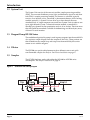
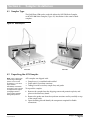
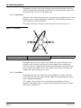
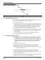
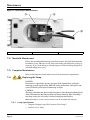
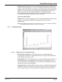
1
85288
QuikChem® 8500
FIA
Automated Ion Analyzer
© Hach Company, 2004. All rights reserved. Printed in the U.S.A.
te/dk 06/04 1ed
Page 2
Title.fm
Table of Contents
Table of Contents ...................................................................................................................................................3
Safety Precautions .................................................................................................................................................7
Use of Hazard Information ..............................................................................................................................7
Precautionary Labels........................................................................................................................................7
Specifications...........................................................................................................................................................9
Bench Requirements ........................................................................................................................................9
Module Dimensions .........................................................................................................................................9
Electrical Specifications ..................................................................................................................................9
Environmental Specifications .......................................................................................................................10
Section 1 Introduction..................................................................................................................................... 11
1.1
1.2
1.3
1.4
1.5
Scope of Manual ............................................................................................................................................... 11
System Unit.......................................................................................................................................................12
Reagent Pump RP-150 Series..........................................................................................................................12
Dilutor................................................................................................................................................................12
Sampler..............................................................................................................................................................12
Section 2 System Unit Installation ...........................................................................................................13
2.1 Carrying Instructions.......................................................................................................................................13
2.2 Connecting the Power Strip............................................................................................................................13
2.3 Connecting the System Unit ...........................................................................................................................13
2.3.1 Flow Cell Installation ............................................................................................................................14
2.4 Installing the Waste and Sample Lines .........................................................................................................15
2.4.1 Sample Line ............................................................................................................................................15
2.4.2 Waste Line...............................................................................................................................................16
2.5 Installing the Manifold....................................................................................................................................17
2.6 Installing the Data System ..............................................................................................................................18
Section 3 Pump Installation .........................................................................................................................19
3.1 Powering the Pump .........................................................................................................................................19
3.2 Installing Pump Tubing...................................................................................................................................20
3.3 Reagent Pump Initial Test ...............................................................................................................................22
Section 4 Sampler Installation ....................................................................................................................23
4.1
4.2
4.3
4.4
4.5
4.6
Sampler Type ....................................................................................................................................................23
Unpacking the ASX Sampler..........................................................................................................................23
Sampler Setup...................................................................................................................................................24
Mounting the Z-Drive .....................................................................................................................................24
Installing the Probe ..........................................................................................................................................24
Fluidic Connections .........................................................................................................................................25
4.6.1 Connecting the Rinse Station ...............................................................................................................25
4.6.2 Connecting the Sample Line (No Dilutor) .........................................................................................26
4.7 Connecting the Sampler to a PDS200 Dilutor ..............................................................................................26
Section 5 Dilutor Installation ......................................................................................................................27
5.1 Cable Connections ...........................................................................................................................................27
5.2 PDS200 Connections........................................................................................................................................27
Page 3
8500TOC.fm
Table of Contents, continued
Section 6 System Operation .........................................................................................................................29
6.1 Injection Valve Operation ...............................................................................................................................29
6.1.1 Inject State...............................................................................................................................................30
6.1.2 Load State ...............................................................................................................................................30
6.2 Manifold Diagram............................................................................................................................................31
6.2.1 Manifold Symbols..................................................................................................................................32
6.3 Fluidic Connections .........................................................................................................................................35
6.3.1 Flow Fit Connections ............................................................................................................................35
6.3.2 Flared Tubing Connections/Switching Valve Connections ............................................................36
6.3.3 Flow Cell Connections ..........................................................................................................................37
6.3.4 Pump Tube Connections.......................................................................................................................38
6.3.5 Transmission Lines Connections .........................................................................................................39
6.4 Instrument Start-up Test .................................................................................................................................40
6.5 Getting Ready for Analysis.............................................................................................................................40
6.6 Non-photometric Detectors ............................................................................................................................41
6.7 Manifold Installation .......................................................................................................................................41
6.7.1 Injection Valve Connections.................................................................................................................42
6.8 Inert Probe.........................................................................................................................................................44
6.9 Pump Operation..............................................................................................................................................44
6.9.1 Reagent Pump Shutdown Procedure .................................................................................................45
6.9.2 Reagent Pump Maintenance ................................................................................................................45
6.10Temperature Controller...................................................................................................................................46
6.11 Dilutor Setup.....................................................................................................................................................46
6.12Dye Test Standards ..........................................................................................................................................46
6.12.1 Mixing Dye Standards ..........................................................................................................................46
6.13 Calibration Run ...............................................................................................................................................47
Section 7 Maintenance ....................................................................................................................................49
7.1
7.2
7.3
7.4
Cleaning Instructions ......................................................................................................................................49
System Shutdown Procedure .........................................................................................................................50
Manifold Removal Procedure ........................................................................................................................50
Installing/Removing the Heater Assembly .................................................................................................51
7.4.1 Installing the Heater Assembly ...........................................................................................................51
7.4.2 Removing the Heater Assembly..........................................................................................................52
7.5 Wrapping a Heater Mandrel...........................................................................................................................53
7.6 Dilutor Maintenance........................................................................................................................................54
7.7 Sampler Maintenance ......................................................................................................................................54
7.7.1 ASX-500 Series and ASX-400 Series Maintenance ............................................................................54
7.7.2 Rinse Station Tubing Replacement......................................................................................................54
7.8 Maintaining the Pump ....................................................................................................................................55
7.9 Valve Module....................................................................................................................................................55
7.9.1 Replacing the Valve Module ................................................................................................................55
7.9.2 Maintaining the Valve Module ............................................................................................................56
7.10Maintaining the Flow Cell ..............................................................................................................................57
7.11 Replacing the Detector Module .....................................................................................................................57
7.12Manifold Maintenance ....................................................................................................................................58
7.13Computer Maintenance...................................................................................................................................58
7.14Replacing the Lamp .........................................................................................................................................58
7.14.1 Lamp Specifications ..............................................................................................................................58
Page 4
8500TOC.fm
Table of Contents, continued
7.14.2 Changing the Lamp...............................................................................................................................59
7.15Replacing Fuses ................................................................................................................................................60
7.15.1 PDS Fuse Replacement .........................................................................................................................60
7.15.2 Reagent Pump RP-150 Fuse Replacement .........................................................................................60
7.16Parts Description ..............................................................................................................................................60
Section 8 Troubleshooting Guide .............................................................................................................61
8.1 Valve Timing .....................................................................................................................................................62
8.2 Sampler Timing ................................................................................................................................................62
8.3 Air Spike Troubleshooting ..............................................................................................................................62
8.3.1 Random Air Spikes................................................................................................................................62
8.3.2 Patterned Air Spikes .............................................................................................................................63
8.4 Interpreting and Troubleshooting Peak Shapes...........................................................................................63
8.4.1 Refractive Index .....................................................................................................................................63
8.4.2 pH Effect .................................................................................................................................................64
8.4.3 Valve Artifact..........................................................................................................................................65
8.4.4 Carryover................................................................................................................................................65
8.4.5 Flat-topped Peaks ..................................................................................................................................66
8.4.6 No Peaks .................................................................................................................................................67
8.4.7 Noisy Baseline........................................................................................................................................68
8.4.8 Drifting Baseline ....................................................................................................................................69
8.4.9 Negative Peaks and Carrier Contamination......................................................................................70
8.5 Flow Blockages .................................................................................................................................................70
8.5.1 Finding Blockages..................................................................................................................................71
8.6 Injection Valve Troubleshooting ....................................................................................................................71
8.7 Detector Fault ...................................................................................................................................................71
8.8 Flow Cell Leaks ................................................................................................................................................72
8.9 Sampler Troubleshooting ................................................................................................................................72
8.9.1 Sampler Errors .......................................................................................................................................72
8.10Dilutor................................................................................................................................................................72
8.11 Pump Test..........................................................................................................................................................73
8.12Dye Test .............................................................................................................................................................73
8.12.1 Making Universal Dye..........................................................................................................................74
8.12.2 Dye Test for Finding Flow Problems ..................................................................................................74
8.12.3 Dye Test to Determine Valve Problems ..............................................................................................74
8.13Other Common Problems ...............................................................................................................................75
Appendix A Parts and Accessories .............................................................................................................79
Replacement Parts..........................................................................................................................................80
Appendix B Channel Installation ...............................................................................................................83
Installing a New Channel...............................................................................................................................83
Removing the Channel...................................................................................................................................85
Appendix C Ion Chromatography ..............................................................................................................87
Manifold Installation......................................................................................................................................88
Certification ............................................................................................................................................................91
Warranty ...................................................................................................................................................................93
Index ...........................................................................................................................................................................95
8500TOC.fm
Page 5
Page 6
8500TOC.fm
Safety Precautions
Please read this entire manual before unpacking, setting up, or operating this
instrument. Pay particular attention to all danger and caution statements.
Failure to do so could result in serious injury to the operator or damage to the
equipment.
Do not use or install this equipment in any manner other than that which
is specified in this manual.
Use of Hazard Information
If multiple hazards exist, this manual will use the signal word (Danger, Caution,
Note) corresponding to the greatest hazard.
DANGER
Indicates a potentially or imminently hazardous situation which, if not
avoided, could result in death or serious injury.
CAUTION
Indicates a potentially hazardous situation that may result in minor or
moderate injury.
NOTE
Information that requires special emphasis.
Precautionary Labels
Read all labels and tags attached to the instrument. Personal injury or damage to
the instrument could occur if not observed.
This symbol, if noted on the instrument, references the instruction manual for operation
and/or safety information.
This symbol indicates the risk of electrical shock. Only individuals qualified to work with
hazardous voltages should open the enclosure or remove the barrier.
This symbol identifies the location of a fuse or current limiting device.
This symbol indicates high temperatures and a potential burn hazard.
This symbol indicates the presence of devices sensitive to electro-static discharge (ESD)
damage.
This symbol identifies a chemical hazard. Only individuals trained to work with chemicals
should handle chemicals or perform maintenance on chemical delivery systems associated
with the equipment.
This symbol indicates the need for protective eye wear.
This symbol identifies the location of the connection for Protective Earth (ground).
Safety.fm
Page 7
Page 8
Safety.fm
Specifications
Bench Requirements
Ideally, the modules are configured in the following left-to-right order: computer
(with printer, monitor, keyboard, and mouse), sampler, PDS200 Dilutor, reagent
pump, and system unit.
Note: The sampler and dilutor can be placed on top of the optional shelf accessory in order to
conserve bench space.
The bench space required for a QuikChem® FIA System with up to four
channels, dilutor, sampler, computer, and printer is:
•
•
•
Width: 2.72 m (9 ft)
Depth: 0.74 m (2.5 ft)
Height: 0.58 m (2 ft)
Module Dimensions
Table 1 contains the general dimensions for individual modules. Use this table for
any system configuration that differs from the one explained above.
Table 1 Dimensions
Width (cm) *
Depth (cm)*
Height (cm)*
Weight (kg) **
PDS200
12.7
22.5
23.4
4
ASX-500 Sampler ***
52.5
46
25
10
ASX-400 Sampler
16
14
16.5
7.3
Reagent Pump RP-100 (12)
15
26
13
5.6
70.5
62.2
26.7
36.3
69
9
26
4
Module
System unit (4 channels)
SPM
* Divide
dimension by 2.54 to convert to inches.
** Multiply
*** Allow
weight by 2.2 to convert to pounds.
an extra 15 cm of height for probe clearance.
Allow a minimum of 10 cm of free space in the back of the instrument and
between modules for cabling and tubing. This extra space also offers easy access
to the system components.
Note: To allow convenient access to the top and rear of the system, avoid putting the system
under shelving.
Electrical Specifications
• Connect all modules to a surge-protected power strip.
Note: Refer to the back of the modules for the proper requirement.
• This equipment is intended for use in a laboratory.
• Use only cables and power cords supplied by Lachat Instruments.
Specification.fm
Specifications
Page 9
Specifications
Figure 1
General Guide to Single Phase Voltage and Frequencies Worldwide
Northern Japan
50Hz
100-120V / 60Hz
220-240V / 50Hz
General guide to single phase voltage & frequencies
Table 2 Individual Electrical Specifications
Module
ac input voltage
rating or range
ac input frequency
rating or range
Maximum active
power (W),
apparent power
(VA), or current (A)
rating
PDS200
110–240 V ac
50–60 Hz
0.5 A
T, ½ A, 250 V
ASX-500 Sampler
100–240 V ac
50–60 Hz
1.5 A
Fuse not
user-replaceable
ASX-400 Sampler
100–120 V ac
50–60 Hz
200 VA
Fuse not
user-replaceable
100 or 120 V ac
50–60 Hz
15 VA
T, ½ A, 250 V
220 or 240 V ac
50–60 Hz
15 VA
T, ¼ A, 250 V
100–115 V ± 10%
50–60 Hz
5A
T, 6.3 A, 250 V
230 V ± 10%
50–60 Hz
3A
T, 6.3 A, 250 V
Reagent Pump RP-100
System Unit
Fuse rating
Environmental Specifications
Table 3 Environmental Specifications
Temperature
Use
Altitude
Specifications
Page 10
15–35 °C (60–95 °F)
Laboratory
Up to 10,000 feet (3 km) above sea level.
Relative humidity
Up to 92.5% non-condensing
Pollution degree
II
Installation category
II
Specification.fm
Section 1
Introduction
1.1 Scope of Manual
This manual describes the system installation, operation, and maintenance of the
components of the QuikChem® 8500 FIA Automated Ion Analyzer.
The System Unit manages four sample processing modules, or channels,
configured for performing flow injection analysis with photometric detection.
The number of channels can be expanded to eight by adding a second core.
Alternate configurations, such as potentiometric and amperometric detection
methods are described in the analytical method where they are required. For
complete information on the software, refer to the QuikChem FIA Omnion®
Software Manual or the on-line Help system in the software.
Note: If any items are
missing or damaged,
please contact Lachat
Instruments or your sales
representative
immediately. Components
returned for service should
be shipped in the original
packaging material to
protect against damage
during transportation.
The QuikChem® 8500 analyzer is modular in design, and consists of the
following modules:
•
•
•
•
•
•
Dilutor (optional)
Sampler
Reagent Pump (12 or 16 cartridges)
QuikChem FIA System Unit
Computer
Printer (optional)
Note: The Ion Chromatography option is available with this instrument. Refer to the QuikChem Ion
Chromatography User Manual for instructions.
Figure 2
Intro.fm
QuikChem® FIA Automated Ion Analyzer with Shelf (Cat. No. 31079)
Introduction
Page 11
Introduction
1.2 System Unit
The System Unit consists of the core unit and the sample processing modules
(SPM). The core unit distributes power, light, and electronic signals to and from
each SPM. A sample processing module, also known as a channel, typically
consists of an injection valve, a manifold, a photometric detector, and a heating
module (optional). A System Unit can have up to four channels that run
simultaneously. A single computer can control two System Units in order to run
up to eight channels at once. A chemical reaction module, or manifold, is
installed on a channel for the quantitative analysis of an analyte. There are more
than 450 QuikChem methods available for determining over 40 analytes; many
of them in several matrices.
1.3 Reagent Pump RP-150 Series
The multichannel peristaltic pump is used to pump reagents into the manifold. It
also aspirates sample aliquots from the sampler to the valve. These portions are
then loaded into the sample loop and swept into the manifold by the carrier
stream to mix with the reagents.
1.4 Dilutor
The PDS200 uses positive displacement to draw diluent water to mix with
non-flammable samples for analysis. See Dilutor Installation on page 27.
1.5 Sampler
The QC8500 Analyzer works with either the ASX-400 or ASX-500 series
autosamplers. See Sampler Installation on page 23.
Figure 3
QuikChem FIA Cabling Diagram
Introduction
Page 12
Intro.fm
Section 2
System Unit Installation
2.1 Carrying Instructions
•
•
•
A four-channel system weighs 36.3 kg (80 lb). Two people are required to
move the system between locations. Use caution when moving the system to
prevent injury.
Lift the System Unit and channels from the bottom. Do not lift by the
front panel.
Always support the entire instrument (e.g., with a cart or a board) while
transporting.
2.2 Connecting the Power Strip
1. Connect the power strip to a power supply.
2. Position the power strip on the bench so that other components can be
connected.
3. Leave the power strip “off” while installing other system components.
2.3
Connecting the System Unit
Note: Do not position the
equipment in any way that
will prevent access to the
on/off switch. See Figure 4.
1. Connect the power cord to the power outlet located on the left hand side of
the System Unit (Item 2 in Figure 4). The other end of the cable should be
connected to the power strip.
Note: Keep the power strip turned off.
2. Locate the 9-pin connector of the cable attached to the reagent pump. Plug
this connector in the outlet for Pump 1 (Item 4 in Figure 4) on the interface
panel, located on the left-hand side of the System Unit.
3. Connect one USB cable to the outlet labeled for “USB in” (Item 5 in Figure 4).
The other end will connect to the computer.
Note: If the system has more than four channels, connect a second set of cables to the second
System Unit.
Figure 4
System Unit Connections
1. On/Off Switch
3. High Pressure Pump (IC only)
5. USB In (from Computer)
2. Power for System Unit
4. Pump Connectors
6. USB Out (to second Unit or other USB device)
SystemUnitInstall.fm
System Unit Installation
Page 13
System Unit Installation
2.3.1
Flow Cell Installation
1. Insert the flow cell into the detector with the printed side (bottom) down.
The flow cell is keyed and should be inserted in the corresponding slot of the
detector (Figure 5).
2. Make sure the flow cell is pushed all the way in the slot. The bottom flared
tubing connector on the flow cell is the inlet, and the top connector is the
outlet. When installing a manifold (reaction module), it is very important to
make the connections accordingly, so air bubbles do not get trapped in the
flow cell. See Figure 6.
3. Connect the top connector (outlet) to the waste line.
Figure 5
Flow Cell
1. To Waste
Figure 6
2. Flow Cell Body
3. Inlet
Flow Cell Connectors
1. To Waste
System Unit Installation
Page 14
2. Inlet (from manifold)
SystemUnitInstall.fm
System Unit Installation
2.4 Installing the Waste and Sample Lines
Figure 7
2.4.1
Sample Loop Valve
Sample Line
A sample line consists of the following: a union connector, 130 or 190 cm of
Teflon® tubing 0.8 mm (0.032 in.) i.d., two pump tube adapters, a green-green
pump tube with its ends trimmed to 2 cm past both green tabs, and 30 cm of
Teflon tubing 0.8 mm (0.032 in.) i.d.
1. Trim the ends of a green-green pump tube to 2 cm past both green tabs
(Figure 8). This procedure only applies to the green-green pump tube used in
a sample line. All other pump tubes do not need to be trimmed
Note: Refer to the QuikChem method to find the pump tube color to be used as a sample line.
Most manifolds will use a green-green pump tube, but there are some exceptions.
Figure 8
Trimming the Green-Green Pump Tube
1. Scalpel
2. Green-Green Pump Tube
3. Green Tab (2)
2. Mount the sample line pump tube into a pump tube cartridge (Figure 9). Do
not clamp down the cartridge on the pump. Refer to System Operation on
page 29 for further details.
Figure 9
Mounting the Sample Line Pump Tube
1. From Probe
2. To Injection Valve
3. Connect the 30 cm Teflon tubing end to port 6 of the injection valve.
4. Connect the 130 or 190 cm Teflon tubing to the probe on the sampler.
SystemUnitInstall.fm
System Unit Installation
Page 15
System Unit Installation
2.4.2
Waste Line
A waste line consists of the following: 13 cm of Teflon tubing 0.8 mm i.d., a
pump tube adapter, 150 cm of Tygon tubing 1.5 mm i.d., a glass weight and a
plastic nipple. See Figure 10.
Figure 10 Waste Line
1. 13 cm Teflon 0.8 mm i.d.
3. 150 cm Tygon 1.5 mm i.d.
5. To waste container
2. Adapter
4. Glass Weight
6. Nipple
7. From Flow Cell or Valve (port 5)
• A waste line should be connected to port 5 of the injection valve and the top
connector of the flow cell.
• When running two or more channels simultaneously, interconnect adjacent
valves by installing 15 cm of 0.8 mm Teflon tubing between ports 5 and 6
(Figure 11). The waste channel farthest from the System Unit will drain
directly into the waste container. Refer to System Operation on page 29 for
details.
System Unit Installation
Page 16
SystemUnitInstall.fm
System Unit Installation
Figure 11 Flow Injection Connections
1. System Unit
3. Channel 2
5. Waste Lines
7. Waste Line
2. Channel 1
4. Channel 3
6. Waste Container
8. Sample Line
The glass weight end of the waste line should be placed in a proper waste
container. The waste line should never be submerged in the waste solution
because this may cause back pressure and flow restrictions. Make sure the waste
solution is always dripping into the container.
2.5 Installing the Manifold
Figure 12 Flow Injection Analysis
1. Sample Line
4. To Waste
7. Manifold Configuration Varies
2. Sample Loop
5. Interference Filter
8. Carrier Line
3. To Manifold Inlet
6. From Manifold Outlet
9. Waste or Next Valve
SystemUnitInstall.fm
System Unit Installation
Page 17
System Unit Installation
The manifold is the reaction module where the chemistry occurs. Specific
installation requirements are detailed in the Manifold Diagram (page 31) included
with each chemistry method.
1. On the valve, connect port 1 to port 4 with the sample loop.
2. Connect the Manifold Outlet to the Flow Cell Inlet.
3. Install the Interference Filter.
4. Connect the carrier line to port 2 on the valve.
5. Connect the tubing from port 3 to the connector labeled “From Valve”.
6. Attach one end of a waste line to the Flow Cell Outlet. Drop the other end into
a waste container.
2.6 Installing the Data System
Follow the manufacturer’s instructions for set-up of the computer, keyboard,
monitor, and mouse.
For Data Systems purchased from Lachat, the Omnion software is installed at the
factory.
For customer-supplied systems, refer to the Omnion User Guide for software
installation instructions.
System Unit Installation
Page 18
SystemUnitInstall.fm
Section 3
Pump Installation
1. Set the pump on the bench (Figure 2 on page 11).
2. Connect the power cord to the power strip. Leave the power strip switch off.
3. Connect the power cord to the mains supply socket on the back of the pump
(Figure 13).
Figure 13 Power Cord Connection
1. Main Supply Socket
2. Power Cord
4. Connect the analog cable to the back of the pump (Figure 14).
Figure 14
Analog Cable Connection
5. Connect the other side of the analog cable to the left panel of the QuikChem
System Unit. See Connecting the System Unit on page 13.
3.1 Powering the Pump
1. Turn on the power strip, then turn on the power switch on the back of the
pump (Figure 15). The top panel will show the set speed of 35.
ReagentPumpInstall.fm
Pump Installation
Page 19
Pump Installation
Figure 15 Locating the Power Switch
1. Power Switch
3.2 Installing Pump Tubing
1. Remove all of the pump cartridges by pressing the cartridge holder against
the pump, then lifting the cartridges out (Figure 16).
Figure 16
Removing the Pump Cartridges
1. Cartridge
2. Cartridge Holder
3. Press Down
2. Place the pump tubing onto the cartridges (Figure 17). Make sure that the tabs
lock into the adaptor.
Pump Installation
Page 20
ReagentPumpInstall.fm
Pump Installation
Figure 17 Placing the Pump Tubing onto the Cartridges
1. Tension Lever
3. Adapter
5. To Injection Valve or Manifold
2. Pump Tube Cartridge
4. Pump Tube Tab
6. Pump Tube
7. From Probe or Reagent
3. Move the tension lever to the right-most position (“up” position).
4. Install the pump cartridge by engaging one side of the cartridge onto the
cartridge holder, then clamp down the other side (Figure 18). The tension
levers should always be on the left side of the pump. An arrow indented on
top of the cartridges shows the flow direction.
The pump should be moving when the cartridge is clamped down.
Figure 18 Installing the Pump Cartridge
5. Move the tension lever to the left until it clicks into place (Figure 19). The
tension lever should be approximately at the 12 o'clock position.
Note: Release tension by moving the lever back to the right.
6. Store unused cartridges.
ReagentPumpInstall.fm
Pump Installation
Page 21
Pump Installation
Figure 19 Setting the Tension Lever
1. One Click Back
3.3 Reagent Pump Initial Test
1. Make sure that the Omnion software is not active at this time. Press the
NORMAL RUN button. The pump should be running at normal speed of 35.
The NORMAL LED will be illuminated. If the display shows a different
speed, press the ARROW button to change the setting to 35.
2. Press the MIN button. The MIN LED will be illuminated. The display will
show a speed of 4.
3. Hold down the MAX button until the MAX LED is illuminated. The display
will show the speed of 999. The pump should go back to the original speed
when the MAX button is released.
4. To stop the pump, press the MANUAL RUN/ STOP button. No LEDs will be
illuminated, but the display will show “35” (the pump speed).
5. Press the MANUAL RUN/ STOP button again. The MANUAL LED will be
illuminated. The pump will be running at normal speed of 35.
6. Press the MANUAL RUN/ STOP button to stop the pump. To repeat any of the
steps above, turn off the pump and start with Step 1.
7. If any of the steps above fail, contact Lachat Technical Support or a local
Lachat Representative.
Pump Installation
Page 22
ReagentPumpInstall.fm
Section 4
Sampler Installation
4.1 Sampler Type
The QuikChem 8500 can be used with either the ASX-500 Series Sampler
or the ASX-400 Series Sampler (Figure 20). Installation is the same for both
samplers.
Figure 20 Autosamplers
ASX-500
ASX-400
4.2 Unpacking the ASX Sampler
Note: If any of these items
are missing or damaged,
please contact Lachat
Instruments or your sales
representative
immediately. Instruments
returned for service should
be shipped in the original
packaging material to
protect against damage
during transportation.
ASX samplers are shipped with:
• Sample tray(s), assembled and installed
• Probe tube in styrofoam container
• Tubing kit with waste line, sample line, and probe
To unpack the sampler:
1. Remove the sampler from the shipping carton and protective plastic, and
place on the laboratory bench.
2. Remove the probe arm from the styrofoam container and lay carefully on top
of the sample racks.
3. Open the tubing kit and identify the components required for fluidic
connections.
SamplerInstall.fm
Sampler Installation
Page 23
Sampler Installation
4.3 Sampler Setup
1. Connect the power cord to the power strip that is powered off.
2. Connect the RS232C cable to the 9-pin connector (COM1) on the back of the
sampler.
3. Connect the other end of the RS232C cable to COM1 on the computer.
4.4 Mounting the Z-Drive
Except for the Z-Drive, the Sampler is assembled at the factory. To mount the
Z-Drive on the sampler arm:
1. Remove thumbscrews and bushings from the drive block located on the
sampler arm (Figure 21 on page 25).
2. Mount the x-axis slider block onto the arm tube.
3. Secure the slider block finger-tight with the 12-mm thumbscrews (installed
from the top).
4.5 Installing the Probe
1. Loosen the probe knob on the probe tube slider and remove the piece of
tubing installed for shipping. Lift the probe tube slider until it stops.
Note: The tan knob will come off without the tubing or probe to hold it in place.
2. The guide slider will move to the upper position with the probe tube slider.
Using the wheel in the back of the sampler, lower both sliders until the guide
slider is about 1 mm from the top. Make sure that the two sliders are in
contact.
Note: Always move the sliders using the wheel at the back of the sampler to avoid crimping
the PEEK tubing.
3. Install the sample probe through both sliders, the probe knob, and the
opening on the probe guide plate. Keep the sliders about 1 mm from the top.
Adjust the probe so the tip is 3 to 6 mm below the guide plate. Secure the
probe by tightening the probe knob on the probe tube slider.
4. Move the sampler arm to the rinse station (extreme left position in the
standards rack). Verify that the probe tip clears the top of the rinse station
when the sampler is in the home position.
Sampler Installation
Page 24
SamplerInstall.fm
Sampler Installation
Figure 21 Probe Tube Assembly
1. Sipper Assembly Tube
4. X-Axis Block
7. Home Position Flag
2. Z-Drive Assembly
5. Y-Axis Lead Screw
8. Sample Probe Guide Plate 11. Sample Transfer Tubing
3. Thumbscrews with Bushings 6. Slider Block Guide Rail
10. O-ring
9. Z-Axis Slider
4.6 Fluidic Connections
4.6.1
Connecting the Rinse Station
Rinse solution is pumped into the bottom of the rinse station and drains to a
waste container through drain tubing attached at the top of the station
(Figure 22).
1. Connect the rinse-in end of the wash line assembly to the inlet fitting
(bottom).
2. Install the pump tube with the purple pump tube tabs on the pump. See
Installing Pump Tubing on page 20.
Note: The outlet of the tube on the right side of the pump attaches to the inlet of the wash bath
(Figure 22).
Do not lock down the right side of the pump cartridge until ready to perform
the test.
3. Drop the other end of the wash line into the rinse solution.
4. Connect one end of the Tygon drain tubing to the drain fitting (top). Drop the
other end into a waste container.
SamplerInstall.fm
Sampler Installation
Page 25
Sampler Installation
Figure 22 Rinse Station Diagram
1. Wash Bath
3. Flow
5. Rinse-In Tubing
7. Drain Tubing for Waste
2. Mounting Block
4. Inlet Fitting
6. From Pump
8. Drain Fitting
4.6.2
Connecting the Sample Line (No Dilutor)
1. Connect the end of the sample line with the union fitting to the probe.
2. Install the pump tubing (green collar locks) in the pump. See Installing Pump
Tubing on page 20. Do not lock down the right end of the pump tubing.
3. Connect the sample line to the injection valve on the system unit.
4.7 Connecting the Sampler to a PDS200 Dilutor
Systems using a PDS200 dilutor require the ASX-500 Series Sampler and a dual
probe. See Dilutor Installation on page 27 for installation instructions.
Sampler Installation
Page 26
SamplerInstall.fm
Section 5
Dilutor Installation
The PDS200 uses positive displacement to draw deionized water or other diluent to mix
with non-flammable samples for analysis.
For operation, the PDS200 Dilutor requires:
• An ASX-500 Series autosampler with upgraded firmware, ASX-500 Series serial
number 080313 or greater. (For older ASX-500 samplers, contact Technical Support
at 1-800-247-7613 or [email protected].)
• Installation of Omnion 3.0.218 or higher.
5.1 Cable Connections
1. Make sure the dilutor power switch is off (Figure 23).
2. Turn off and disconnect the power strip.
3. Connect the Desktop Power Supply with power cable (Lachat Part. No. 5011200) to
the dilutor (Figure 23). Plug the other end into the power strip.
4. Connect the male connector of the 9-pin serial cable to the back of the dilutor
(Figure 23B). Connect the other end to the dilutor port on the back of the
autosampler.
Figure 23
PDS200 Dilutor
1. Power Indicator Light
3. Serial Cable Connector
2. On/Off Switch
4. Solenoid Valve
5. Power Cable Connector
5.2 PDS200 Connections
Note: Probe speed on
existing autosamplers has
been reduced to improve
performance. The
autosampler may produce
a different sound as a
result.
DilutorInstall.fm
1. Connect the DI Water Line to Port A of the solenoid valve of the dilutor (Item 1 in
Figure 24). Place the other end of the line into the DI water (Figure 25).
2. Connect the Sample Line Assembly to port B of the solenoid valve
(Item 2 in Figure 24).
3. If necessary, mount the Dual Probe Assembly onto the autosampler. The probe guide
may need to be rotated to accommodate the dual probe.
4. Connect the probe sample line (attached to the bent tube of the Dual Probe
Assembly) to port C of the solenoid valve (Item 3 in Figure 24).
5. Ensure the ferrule on the line from the straight tube of the Dual Probe Assembly is
flush with the end of the tubing (Item 5 in Figure 24).
6. Insert the connector from the straight tube of the Dual Probe Assembly into port D of
the dilutor (Figure 25) and tighten.
Dilutor Installation
Page 27
Dilutor Installation
7. Ensure the ferrule on the dilutor end of the Diluent Line Filter Assembly is flush
with the end of the tubing ( Item 5 in Figure 24).
8. Insert the connector from the Diluent Line Filter Assembly into port E of the dilutor
and tighten (Item 2 in Figure 25).
9. Insert the filter end of the Diluent Line Filter Assembly into the diluent ( Item 12 in
Figure 25).
Figure 24
Tubing Connectors and Ferrule Placement
Port C
Port A
Port B
1. To DI Water Port A
3. To Sample Probe Line Port C
2. To Pump/Analyzer Port B
4. Ferrule
Figure 25
5. Flush
Dilutor and Solenoid Valve Fluidic Connections
1. To Sample Probe
5. Sampler/Computer Connection
9. Sampler Power Supply
2. To Diluent
6. Sampler Power Connection
10. To Pump/Analyzer (P. N. 21936)
3. Dual Probe Assembly (P. N. 29915)
7. Dilutor Power Connection
11. DI Water Line (P. N. 29940)
4. Dilutor/Sampler Serial Cable
8. Dilutor Power Supply
12. Diluent Line Filter Assembly (P. N. 29920)
Dilutor Installation
Page 28
DilutorInstall.fm
Section 6
System Operation
The Lachat QuikChem® System automates wet chemical determinations using
the principle of Flow Injection Analysis. The peristaltic reagent pump draws
sample from the sampler into the injection valve. Simultaneously, reagents are
continuously pumped through the system. The sample is loaded into the sample
loop of one or more injection valves. The injection valve is then switched to
connect the sample loop in line with the carrier stream. This sweeps the sample
out of the sample loop and onto the manifold.
The sample and reagents then merge in the manifold (reaction module) where
the sample can be diluted, concentrated, dialyzed, extracted, incubated, and
derivatized. Mixing occurs in the narrow bore tubing under laminar flow
conditions. For each method, the operating parameters are optimized to address
high sample throughput, high precision and high accuracy. The FIA peaks are
transient, reflecting the non-steady state conditions normally employed. In FIA,
equilibrium is usually not attained.
6.1 Injection Valve Operation
The valve consists of a stator and a rotor (Figure 26). The rotor has three tiny
grooves through which liquid passes. The direction in which the liquid flows
through the valve depends on the alignment of the grooves with the holes on the
stator.
Figure 26 Stator and Rotor
1. Stator
2. Rotor
The six-port injection valve provides port connections for the following:
Sample Line
The sample is pumped from the sampler or the sample probe to port 6 on the injection valve.
Sample Loop
Tubing that connects ports 1 and 4. The sample loop determines the volume of sample to be injected onto
the manifold for analysis.
Carrier Line
This is an artificial blank solution that will carry or sweep the sample onto the manifold. The carrier line input
is always connected to port 2. The carrier solution and the carrier line to be used for an analysis are specified
in the QuikChem method.
Manifold
The carrier stream exits the valve at port 3 and flows to the manifold.
Waste Line
When running one channel only, the waste line is connected to port 5 on the injection valve. When running
two or more channels simultaneously, port 5 of the first injection valve is connected to port 6 of the second
injection valve. Port 5 of the second injection valve will then be connected to waste. The connection between
ports 5 and 6 consists of 15 cm Teflon tubing 0.8 mm i.d.
SystemOperation.fm
System Operation
Page 29
System Operation
The injection valve has two states: the inject state and the load state. The valve
will be moving bi-directionally between those two states. When the system is not
in operation, the valves rest in the inject state.
6.1.1
Inject State
When the valve is in the inject state, the carrier stream is pumped into port 2 and
directed to port 1 to flow through the sample loop. The carrier then comes out
port 3 and flows onto the manifold.
The sample stream goes into port 6 and out port 5 to waste. See Figure 27.
Figure 27 Inject State
1. Sample Loop
3. To Manifold
2. Carrier Line
4. Waste Line/Next Valve
5. Sample Line/Tubing from Adjacent Valve
During the inject state, the sample loop is filled with carrier. When the valve
switches to the load state, some carrier will be trapped in the sample loop.
The carrier that was trapped in the sample loop at the inject state will be swept
out to waste by the sample stream. The sample stream will pass through the
sample loop and eventually go to waste.
6.1.2
Load State
During the load state, the sample loop is being filled with sample. When the
valve switches back to the inject state, the sample flowing through the sample
loop is trapped momentarily.
This sample, whose volume can be calculated from the length and inner
diameter of the tubing used, is swept onto the manifold by carrier for reaction
and analysis. See Figure 28.
System Operation
Page 30
SystemOperation.fm
System Operation
Figure 28 Load State
1. Sample Loop
3. To Manifold
2. Carrier Line
4. Waste Line/Next Valve
5. Sample Line/Tubing from Adjacent Valve
6.2 Manifold Diagram
A manifold is the reaction module where the chemistry occurs. This section
explains how to read a manifold diagram.
Each QuikChem Method contains a manifold diagram (Figure 29). The manifold
diagrams depict reagent flow rather than the manifold layout. Both diagrams
represent the same manifold. The second diagram depicts the new Lachat
nomenclature.
SystemOperation.fm
System Operation
Page 31
System Operation
Figure 29 Sample Manifold Diagrams
Pump Flow
From Water
To Wash Bath Fill
To Waste
From Wash
Gray
2.5 in.
Color Reagent
1 in.
Carrier
Sample (green)
To Port 6 of
Next Valve or
Sample Loop = Microloop
Filter: 480 nm
To
Flow
Cell
OR
Pump Flow
Probe Rinse
Green
Gray
OrangeYellow
Flow
Cell
2.5 in.
Color Reagent
1 in.
Waste
Carrier
Sample (green)
Sample Loop = Microloop
Interference Filter = 480 nm
6.2.1
To Port 6 of
Next Valve or Waste
Manifold Symbols
6.2.1.1
Mixing Coil Symbol
Mixing coils are typically constructed with 0.8 mm i.d. Teflon tubing wrapped
on a coil support. The mixing coil symbol (Figure 30) may also represent a back
pressure loop. Please read any notes regarding this in the QuikChem methods.
Figure 30 Mixing Coil Symbol
1 in.
1 in.
The number next to the mixing coil symbol indicates the length of the coil
support. The length of the coil support is measured from hole to hole. The length
of Teflon tubing wrapped on the coil support is specified below the manifold
diagram section in each QuikChem method.
System Operation
Page 32
SystemOperation.fm
System Operation
6.2.1.2
Coil Support
See Table 4 for lengths of tubing needed for wrapping coil supports.
To wrap the support:
1. Insert the tubing in one of the coil support holes. Leave approximately 12 cm
of loose tubing for connecting the coil to any fitting.
2. Start wrapping the tubing on the coil support, being careful not to
over-tighten.
3. When there is only 12 cm of tubing left, pass the tubing through the other
hole. Make sure the two ends are passed through the holes in the same
direction. See Figure 31.
Figure 31 Coil Support
Table 4 Coil Support Tubing Lengths
Coil Support (inches)
Tubing (cm)
1
70
2
135
2.5
168
4
255
8
550
Alternating *
255
* The alternating coil support has 6 holes. When wrapping the tubing on the coil support, change
the tubing direction (clockwise or counterclockwise) every time the tubing is passed through a
hole.
Note: Refer to the QuikChem method to obtain the correct length of tubing needed for the analysis.
Table 4 contains general information. Some manifold diagrams have all dimensions in the
metric system.
6.2.1.3
Injection Valve Symbols
The injection valve (Figure 32 on page 34) will be located on the left side of every
channel of the System Unit. The numbers around the hexagon represent the six
ports on the valve. The zig-zag or coil symbols represent sample loops. This is
the tubing connected between ports 1 and 4. The length of this tubing is specified
on the manifold diagram. Read the notes for the QuikChem FIA System in the
method. The lines coming out of the hexagon represent the Teflon tubing
connected to the valve ports.
SystemOperation.fm
System Operation
Page 33
System Operation
Figure 32 Injection Valve Symbols
6.2.1.4
Pump and Pump Flow Symbols
Figure 33 represents the reagent pump. The top arrow indicates the pump flow
direction. The other two upper lines refer to the rinse water lines attached to the
wash reservoir in the Sampler. The wash line is connected to the bottom nipple
of the wash reservoir.
Figure 33 Pump and Pump Flow Symbols
From Water Pump Tube
To Wash Bath Fill
To Waste
Gray
Color Reagent
Carrier
Sample (green)
6.2.1.5
Reagent Line Representation
The reagents and sample lines are represented by a straight line crossing the
rectangle (Figure 34). The specified color is the color of the tabs of the pump
tubes to use for that line. All pump tubes have different color tabs on each side to
indicate that the tubing has a certain inner diameter. The direction of pump tube
installation is not critical (Figure 35).
Figure 34 Reagent Line Representation
Gray
Color Reagent
Carrier
Sample
System Operation
Page 34
SystemOperation.fm
System Operation
Figure 35 Pump Tube
The reagent lines are labeled to indicate the solution going through that line. The
carrier line is always connected to port 2 of the valve. The sample line is always
connected to port 6 of the valve.
6.2.1.6
Tee Connector Symbol
Every intersection of two reagent lines represents a tee connector (Figure 36).
Note: The manifold
diagram examples have
only one tee connector.
Tee connectors combine two reagents. The tee has three ports: two side ports
(inlets) where the two reagent lines are connected, and a top port (outlet)
which may be connected to a mixing coil or whatever is indicated in the
manifold diagram.
Figure 36 Tee Connectors Symbols
Tee Connector
2.5 in.
OR
1in.
6.2.1.7
Heating Coil Symbol
Figure 37 represents a heating coil installed on the System Unit. Set the heater at
the temperature specified in the diagram (60° C in our example). The length of
tubing wrapped on the block is specified in the QuikChem method.
Figure 37 Heating Coil Symbols
OR
60°
60°
6.3 Fluidic Connections
6.3.1
Flow Fit Connections
Tee connectors, union connectors, and pump tube adapters are all examples of
flow fit connections. Tube connectors used on tee connectors, union connectors,
and pump tube adapters pass Teflon tubing through two Viton O-rings into a
seat (Figure 38). A tube connector is finger-tightened to compress the O-rings
around the tubing for a leak-proof seal.
Note: Injection valves use
one-piece fittings.
SystemOperation.fm
Tube connectors used on the injection valves do not require O-rings or ferrules.
System Operation
Page 35
System Operation
Figure 38 Connecting a Teflon Tubing Connection to a Union Fitting
1. Union Fitting
3. Tube Connector (Nut)
2. O-ring (2)
4. Teflon Tubing
When a fitting is new, the Viton O-rings are very tight. In this case, unscrew the
tube connector and remove the O-rings with the O-ring remover provided in the
accessories kit. Insert the Teflon tubing through the center of the connector and
the two O-rings, making sure that the threaded end of the connector is towards
the tubing end. Screw the tube connector in the union fitting. The screw
connector should be finger-tight.
Note: Tubing may become slippery due the natural oil on fingers. Use a small piece of paper to
hold the tubing to avoid this problem.
After some use, the O-rings will become more flexible and allow more rapid
tube connections.
1. Insert the tubing by loosening the tube connector one quarter turn.
2. Slide the tubing through the connector into the union fitting until it stops.
3. Press firmly to push the tubing through the O-rings. Avoid crimping the
tubing.
4. Finger-tighten the nut. To ensure that a seal is made, gently pull on the tubing.
It should not easily pull out of the fitting.
6.3.2
Flared Tubing Connections/Switching Valve Connections
The switching valve is a manual valve designed to direct the flow in the
manifold. Some manifolds that include a column (example: cadmium column for
nitrate reduction) may have this type of valve.
A flared tubing connection requires flared tubing 0.5 mm i.d. from the switching
valve flare kit (Lachat Part No. 50962). The valve connector is shorter than the
tube connector. See Figure 39 on page 37.
To make a connection with the valve:
1. Slide a metal washer onto the flared tubing, then a valve connector. The
threads of the connector should face the metal washer.
2. Screw the connector into the valve and finger-tighten.
System Operation
Page 36
SystemOperation.fm
System Operation
Figure 39 Connecting Flared Tubing
1. Tubing
3. Metal Washer
2. Valve Connector
4. Flare
6.3.3
5. Switching Valve
Flow Cell Connections
Flow cell connections are a combination of the connections described in
Section 6.3.2.
1. Slide three O-rings over a flow cell flare.
2. Insert this flare into a flow cell connector so the threaded end faces the
O-rings. See Figure 40.
3. Screw the connector into the flow cell, finger-tight.
Figure 40 Connecting the Flow Cell
1. Flow Cell Connector
3. Flare
2. Flow Cell
4. O-Ring (3)
4. Place the flow cell into the lower slot of the detector (Figure 45 on page 42).
Press firmly until it snaps into place. (The flow cell is keyed so it can only be
inserted one way.)
5. Connect the top tubing of the flow cell to a waste line. The bottom tubing
should be connected to the fitting on the manifold next to the label To Flow
Cell (Figure 48 on page 47).
6. Refer to the QuikChem Method manifold diagram for details.
Note: If flow cell connections are reversed, air bubbles may become trapped in the flow cell.
This can cause baseline shifts and peak problems.
SystemOperation.fm
System Operation
Page 37
System Operation
Figure 41 Flow Cell, Bottom View
1. Union Connector
3. Flow Cell seen from below
5. Pump Tube Adapter
2. From Manifold
4. To Waste
6. Upper Connector
6.3.4
Pump Tube Connections
A pump tube adapter connects the Teflon tubing to Tygon tubing (Figure 42).
This is typically used for connecting pump tubes to the manifold tubing. It is
also used to connect the flow cell outlet to a waste line.
1. Obtain a pump tube adapter. If this connection will be used for the sample
line, remove the metal nipple from the pump tube adapter with a pair of
pliers.
2. Unscrew the black or white collar. Make sure the correct collar for the pump
tube is in use. See Table 5.
3. Slide the collar onto the pump tube, making sure the threaded end faces the
tubing edge.
4. Insert the pump tube adapter into the pump tube. Slide the pump tube as far
as it can go.
5. Screw the collar onto the pump tube adapter.
System Operation
Page 38
SystemOperation.fm
System Operation
Table 5 Pump Tube Collars
Collar
Pump Tube Color
White
Orange - White
White
Black
White
Orange
White
White
Black
Red
Black
Gray
Black
Yellow
Black
Yellow - Blue
Black
Blue
Black
Green
Black
Purple
Figure 42 Making Pump Tube Connections
1. Teflon Tubing, 0.5 mm i.d. 3. O-rings (2)
5. Metal Nipple
2. Tubing Connector (Nut)
6. Collar
6.3.5
4. Pump Tube Adapter
7. Pump Tube
Transmission Lines Connections
Depending on the inner diameter of the Tygon tubing, two pieces of tubing can
be connected by a metal or a plastic nipple. The metal nipple is used for small
inner diameter tubing. The plastic nipple is for large inner-diameter tubing
(Figure 43).
SystemOperation.fm
System Operation
Page 39
System Operation
Figure 43 Using the Metal or Plastic Nipple
1. Metal Nipple
2. Plastic Nipple
6.4 Instrument Start-up Test
All the modules of the System QuikChem FIA should be connected to a power
strip. All the individual module switches should be ON.
1. Turn on the power strip.
2. The ASX-500 series and ASX-400 series samplers will automatically perform
an operation check by moving the probe over the wash bath. It will eventually
place the probe directly above the wash reservoir. Later, when accessing
Omnion on the computer, the probe will go down into the wash reservoir.
3. The computer monitor will show that Windows® is loading.
4. Look through the side panel on the System Unit to see if the lamp is on. It may
take up to one minute for the lamp to turn on. This delay lengthens the life
span of the lamp.
5. The heater controllers will show the current temperature of the blocks.
6. Leave the pump turned off until ready to run the test.
6.5 Getting Ready for Analysis
Note: For Windows versions prior to XP and 2000 (95, 98, NT, and ME), power on the QC8500
instrument and verify connection to the PC before launching Omnion. If the USB connection
to the instrument is lost (e.g. momentary interruption of power to the PC or QC8500
instrument from power surges), reboot the PC to reestablish communication. Windows 2000
and XP will prompt the user to recover the link without rebooting. Lachat Instruments
strongly recommends using Windows 2000 or Windows XP operating systems with the
QC8500.
Once the instrument is powered up:
1. Determine if the analysis to be performed requires a special detector.
Most QuikChem methods require a photometric detector module.
Note: The Ion Chromatography (IC) channel (optional) uses a conductivity module instead of
a photometric detector module.
2. Install the manifold on the channel that will run the analysis. Refer to
Section 6.7 Manifold Installation on page 41 and Figure 44 on page 42.
3. Make all the injection valve fluidic connections. Refer to Section 6.7.1 Injection
Valve Connections on page 42.
4. Make all the flow cell fluidic connections when using a photometric detector.
Refer to Section 6.3.3 Flow Cell Connections on page 37.
System Operation
Page 40
SystemOperation.fm
System Operation
5. Set all pump tubes on the pump. The number of pump tubes varies from
method to method, but the sample line and at least one wash line (for the
sampler) must be used for any analysis.
6. Run deionized water through all the lines to make sure there are no leaks.
When performing nitrate analysis, or any other method that requires a
column, make sure that the column is off line. If no leaks are found, put the
reagents in line.
Note: Follow the QuikChem method notes for start-up of specific methods.
7. Set the heater controller temperature in the Omnion software under the
Analyte tab. Refer to the QuikChem method for temperature settings. Refer to
the Omnion 3.0 Software User Manual for heater configuration information.
8. If the system has a dilutor, place the diluent line E in the diluent
(i.e. deionized water). Place empty test tubes in the empty tubes rack.
9. Pour the calibration standards into standard vials. Pour some samples into
test tubes.
10. Start the analysis by running a worksheet with standards and samples. Refer
to Figure 48 on page 47.
6.6 Non-photometric Detectors
Some methods require other types of detectors, such as fluoride, flame
photometers, conductivity, pH, etc. Non-photometric detectors, such as an ISE
detector for determination of fluoride, do not require the regular flow cell or
interference filters. Follow the instructions in the QuikChem method for fluidic
connections.
6.7 Manifold Installation
1. Unwrap the manifold from the bubble pack. The manifold is labeled with the
QuikChem method number and the name of the analyte.
2. Remove the sample loop and the interference filter bag taped to the bottom of
the manifold.
3. Place the flow cell in the lower slot in the detector. Insert the interference filter
in the upper slot.
4. Unwind the pump tubes and place the manifold on the sample processing
module or chosen channel. Channel one is always the closest to the System
Unit.
Note: Heater mandrels are
available in four
pre-wrapped lengths:
175 cm, 650 cm, 825 cm,
and 1200 cm. Each
pre-wrapped mandrel is
labeled with the length of
tubing it carries.
SystemOperation.fm
5. Determine whether the manifold is for a heated chemistry. A heated
chemistry manifold board will have a hole for routing the tubing from the
heater to the manifold. For heated chemistries, locate the union connector that
holds the two ends of the tubing needed for the method. Refer to the
QuikChem method to determine which length is needed. Thread both ends
through the hole in the manifold. Make both connections according to the
manifold diagram in the QuikChem method. See Wrapping a Heater Mandrel
on page 53 for more information.
System Operation
Page 41
System Operation
Figure 44 Flow Injection Analysis
Sample
Loop
Sample
Waste
Waste
Carrier
5
6
Valve
4
3
1
Manifold
Detector
2
Reagents
Buffers
Diluents
Figure 45 Photometric Detector
1. Filter
6.7.1
2. Flow Cell
Injection Valve Connections
PORTS 1 AND 4— The tubing that connects these two ports is called the
sample loop. The length of the sample loop is specified in the method.
Use 0.8 mm i.d. Teflon tubing for the sample loop unless the QuikChem method
specifies otherwise. See Figure 46 on page 43.
System Operation
Page 42
SystemOperation.fm
System Operation
Figure 46
Input and Output Valve Connection State
1. Sample Loop
3. To Manifold
2. Carrier Line
4. Waste Line/Next Valve
5. Sample Line/Tubing from Adjacent Valve
A sample loop may also be a Microloop, which consists of 12.5 cm or 16 cm of
0.3 mm i.d Teflon tubing.
Note: If the method does not specifically provide the length of the sample loop for the system
QuikChem FIA, add 5.5 cm to the length used with the Lachat AE system.
Example: The method does not specify the sample loop length for the system
QuikChem FIA but the manifold diagram provides information on a sample
loop. If the sample loop specified here is 10 cm, the system QuikChem FIA
will need 15.5 cm of 0.8 mm Teflon tubing between ports 1 and 4.
PORT 2— The carrier line should be connected to port 2. Connect the carrier
line to port 2 at the valve. Use 30 cm of 0.8 mm i.d. Teflon tubing.
PORT 3— Connect 20 cm of 0.8 mm i.d. Teflon tubing between port 3 and the
fitting on the manifold labeled From Valve, unless specified differently in
the method.
PORT 5— Connect 15 cm of 0.8 mm i.d. Teflon tubing between port 5 and the
waste line. When running two or more channels simultaneously, the 15 cm piece
of tubing should be connected from port 5 of the first valve to port 6 of the
second valve. The last valve should have port 5 connected to the waste line.
PORT 6— Connect a sample line to port 6. A sample line typically consists of:
•
•
•
•
130 cm length of Teflon tubing
20 cm length of Teflon tubing
Two pump tube adapters (black collar)
A green-green pump tube with both ends trimmed to leave 2 cm of tubing
beyond the green tabs
All Teflon tubing is 0.8 mm i.d. The 130 cm piece of Teflon tubing is connected to
the probe on the Sampler. The 20 cm piece of tubing should be connected to
port 6 of the valve.
SystemOperation.fm
System Operation
Page 43
System Operation
Figure 47 Tubing Length Requirements
1. Sample Loop (per QuikChem method)
3. 20 cm *
2. 30 cm
4. 15 cm
5. 30 cm
* Suggested length. Port 3 tubing needs to be long enough to reach from the valve to the manifold. No minimum length is
required.
6.7.1.1
Injection Valve Tubing FAQs:
Is the length of tubing critical? The tubing length is critical for the sample
path. Run dye as sample to determine the sample path. The length of the reagent
lines is not critical.
What is the permissible error when measuring tubing? ±2 mm for every
50 cm of tubing.
Allowed error (mm) = ± ( Tubing length ⁄ 50 ) × 2
6.8 Inert Probe
The probe supplied with the system is made of stainless steel. This probe is used
to run with most of the methods. However, some methods require an inert probe
made out of Teflon or other inert materials. Refer to the system notes in the
QuikChem method for this information.
6.9
Pump Operation
When using new pump tubes for the first time, allow the pump to run
approximately ten minutes in order to obtain constant flow rates. Table 6 shows
the functions of each button on the pump.
System Operation
Page 44
SystemOperation.fm
System Operation
Table 6 Pump Button Functions
Button
Function
MIN
Sets the pump speed to 4.
MAX
Sets speed to maximum of 999. Button must be kept depressed in order to maintain maximum
speed.
Note: If this button is depressed too long the pump will stop to prevent the motor burning out.
NORMAL RUN
Normal run starts the pump and permits remote control of the pump standby speed as determined
by the Omnion software at the end of a run or batch.
The pump runs at the displayed speed. Normal speed is 35. Use the UP and DOWN arrows to alter
this setting.
If Omnion is set to Standby speed, the pump will run very slowly and the display will show rc 3. The
display rc 3 indicates remote control speed 3.
MANUAL RUN / STOP
Manual running allows the pump to override the remote control of the standby speed.
This button toggles between manual speed control and manual stop.
If the pump is running, this button will always stop the pump. If the pump is not running, this button
will still override the remote control from the computer and put the pump in manual stop.
The manual run button is commonly used for making the pump go to normal speed in order to prime
the tubing with reagents.
Up Arrow
Increases pump speed setting. Not active when in MIN or MAX modes.
Down Arrow
Decreases pump speed setting. Not active when in MIN or MAX modes.
Place all of the reagent lines into their corresponding containers or in deionized
water. To avoid reagents leaking onto the system, run deionized water through
all of the lines to detect any leaks. If the manifold has a cadmium column, make
sure it is bypassed. Water and air will damage the cadmium column.
Note: Some methods require certain reagents to be pumped first. Example: TKN method has a
buffer solution, which has to be run first to avoid a white precipitate in the manifold tubing.
Check the QuikChem method for instructions.
Refer to Section 3.1 Powering the Pump on page 19 to learn how to mount the
cartridges onto the Reagent pump.
6.9.1
Reagent Pump Shutdown Procedure
1. Press the MANUAL RUN/ STOP button to stop the pump. Turn off the green
power switch or turn off the power strip.
2. Release all of the cartridges. Leaving the pump tubes clamped down for more
than a few minutes causes the tubing to become flat and require replacement.
To release the cartridges, press on the cartridge holder until the pump tube
cartridge is released. The pump tube can be left on the cartridges. The tension
lever has no effect on the pump tube when the cartridge is not clamped down.
6.9.2
Reagent Pump Maintenance
The Reagent Pump RP-100 Series does not require any special maintenance.
When operated according to the guidelines stated in this manual, the tubing is
the only part that needs replacement, depending on the application and the
operating conditions. Use only Lachat tubing to ensure optimal performance.
If a spill occurs, neutralize it immediately. Clean the pump and cartridges well.
Use isopropyl alcohol to clean the rollers. Do not lubricate the rollers with oil. All
pump surfaces should be kept clean and dry.
SystemOperation.fm
System Operation
Page 45
System Operation
6.10 !
Temperature Controller
Note: Always set the run
and post-run temperature
in the Omnion software.
All heater properties, including the run temperature (set-point), when to send the
set-point to the heater element, and post-run set-point, are set in the Omnion 3.0
software. Refer to the Omnion 3.0 User Guide for more information. The
temperature can be viewed real-time with the controller on the heater assembly.
6.11 Dilutor Setup
For systems using the PDS200 dilutor, make sure to place the diluent line in
diluent (usually deionized water). Remember that all triggered dilutions will be
performed at the end of the tray run. All requested dilutions will be performed at
the time the sample is in the tray run sequence.
Triggered dilutions: The instrument recognizes any sample that is over the
concentration range of the method. It allows 10% of the high standard
concentration for extrapolation. The instrument automatically dilutes all
over-range samples. This feature must be specified in the analyte table in the
Omnion software.
Requested dilutions: Program the dilution factor for a specific sample.
This factor is specified in the Run Worksheet. Refer to the Omnion 3.0 User
Guide for more information.
Note: Requested dilutions could be used for making calibration standards from a stock standard.
The tray should include all calibration standards. Specify the same cup number for all of
them (e.g. cup 15). Place the stock standard in that cup (e.g. 15). Indicate the dilution factor
for each calibration standard accordingly.
The dilutor system needs an empty tubes rack for performing dilutions. The
ASX-500 series sampler has the fourth rack reserved for empty tubes.
6.12 Dye Test Standards
To evaluate the operation of the system, run tests with Universal Dye instead of
reagents. This technique is helpful for troubleshooting problems not related to
the reagents.
All of the reagent lines can be put in deionized water. The standards will be
solutions of dye at different concentrations.
6.12.1 Mixing Dye Standards
Make sure that the Universal Dye which comes with the system has been diluted
according to the directions on the label.
Note: The dye will not be detected with the 880 nm filter.
Table 7 shows the quantity of Universal Dye solution and deionized water for
four standards:
Table 7 Dye Standards
System Operation
Page 46
Standard
Deionized Water (mL or g)
Universal Dye (mL or g)
Standard A
50
50
Standard B
75
25
Standard C
87.5
12.5
Standard D
93.75
6.25
SystemOperation.fm
System Operation
1. Locate the Sampler cups for the standards.
2. Pour the standard solutions into the vials. The Dye Test requires four
standard vials.
3. Position the vials on the standards rack, making sure the high standard is in
the first position.
Note: The position of the standards can be any standards rack position, as long its location is
specified in the software.
6.13 Calibration Run
Once the installation of the manifold has been completed, refer to the
Omnion 3.0 Software User Manual for calibration run details.
Figure 48 System Operation
SystemOperation.fm
System Operation
Page 47
Page 48
SystemOperation.fm
Section 7
Maintenance
Preventive maintenance is extremely important to ensure long-term operation.
The following tips will help keep the Lachat QuikChem® 8500 operating at
maximum potential.
Keep all modules clean and dry at all times. This will minimize the time needed
for maintenance and help avoid future repairs. The manufacturer recommends
starting a weekly maintenance schedule and keeping basic spare parts in stock
(Table 8).
Table 8 Basic Spare Parts
Part Name
Recommendations
Pump tubes
Check the manifolds and make a list of the pump tube colors.
Green-green pump tubes are the only spare tubes included
with a new instrument
Teflon tubing
A new instrument includes spare Teflon® tubing. Restock
Teflon tubing when supply is low. Manifold tubing: 0.8 mm i.d.
Low Flow Manifold Tubing: 0.5 mm i.d.
Back-pressure loop: 0.5 mm i.d.
O-rings
Transmission tubing
Restock O-rings when supply is low.
Restock transmission tubing when supply is low.
Refer to Appendix A Parts and Accessories on page 79 to obtain part numbers. Call
Lachat Instruments to obtain a complete parts list.
7.1
Cleaning Instructions
Before using any cleaning or decontamination methods except those
recommended by Lachat Instruments, verify with Lachat Technical Support that
the proposed cleaning method will not damage the equipment.
The general Maintenance Schedule (Table 9) can be used as a quick reference:
Table 9 Maintenance Schedule
Component
Sampler
Dilutor
Pump
Service
Clean surfaces
Daily
Weekly
Clean rods/moving parts
X
Prime dilutor with DI water after using any other
diluent
X
Spray silicone on cloth and rub onto rollers
X
Replace pump tubes
X
Clean surfaces
X
Rinse cartridges
X
Clean unions and tees
Manifolds
Replace O-rings
Replace all tubing
Maintenance.fm
Yearly
X
Clean surfaces
Clean ports and valve connectors
Every 6
Months
X
Clean pump tube adapters
Injection Valves
Monthly
X
X
X
X
X
Maintenance
Page 49
Maintenance
Table 9 Maintenance Schedule (continued)
Component
Detectors
Dry and clean all surfaces
Flow Cells
Replace flares and O-rings
System Unit
Computer
7.2
Service
Keep dry and clean
Daily
Weekly
Monthly
Every 6
Months
Yearly
X
X
X
Clean hard drive
X
System Shutdown Procedure
1. When using a manifold with a column, such as the cadmium column for
nitrate, take the column off-line by rotating the switching valve to the bypass
position. If the manifold has a column, but does not have a switching valve,
turn off the pump and replace the column with a piece of Teflon tubing.
Restart the pump.
Note: Some methods require certain reagents (typically, the buffer) to be removed last. Check the
QuikChem method for instructions.
2. Remove the reagent lines from each reagent and rinse off the lines and glass
weights before putting them into the rinse solutions.
3. If the QuikChem method recommends a rinse solution, place all reagent
transmission lines into the solution and pump for 5 minutes at standard
speed.
Note: This is a critical step in the preventive maintenance of the manifolds.
4. Place transmission lines into deionized water and allow the system to rinse
for 5 to 10 minutes at standard speed.
5. Remove the transmission lines from the deionized water and allow all liquid
to be pumped out of the manifold. Exception: If the manifold has a dialysis
block, leave all reagent lines in deionized water.
6. Turn off the pump and release the pump tube cartridges (Pump Installation on
page 19).
7. Switch off the master power strip after properly closing all files in the
computer.
Note: If a lower set-point temperature is not specified in the software, the heater controller will
remain at the original set temperature. If the method requires a temperature higher than
60º C, lower the temperature setting to 60º C or less before turning the system off.
7.3
Manifold Removal Procedure
1. Rinse the manifold according to Section 7.2.
2. Detach manifold tubing from manifold fitting that is connected to port 3 at
the injection valve. Leave the piece of tubing attached to the injection valve.
3. Detach the output of the manifold from the union on the flow cell tubing,
leaving the union connected to the flow cell flare.
4. Remove the back-pressure loop, if necessary.
5. Detach heating unit tubing from manifold, if necessary.
6. Remove all manifold pump tubes from cartridges.
7. Remove the interference filter from the detector module.
8. Remove the sample loop from ports 1 and 4 of valve.
Maintenance
Page 50
Maintenance.fm
Maintenance
9. Remove the manifold from the channel.
10. Carefully wrap transmission lines around manifold and store it in the
supplied plastic bubble bag.
11. To install another manifold, refer to Installing the Manifold on page 17.
7.4
Installing/Removing the Heater Assembly
CAUTION
Turn off System Unit power and allow the heater to cool completely before
touching the heater element or mandrel, or before installing or removing the
heater assembly.
7.4.1
Installing the Heater Assembly
Refer to Figure 49 on page 52.
1. Lift the existing drip tray assembly out of the channel. Disconnect the leak
detector cable and remove the tray.
Note: If removing a heater assembly, see Removing the Heater Assembly on page 52.
2. Connect the 6-pin heater controller cable.
3. Connect the 3-pin leak detector cable.
4. Connect the 2-pin heater element cable.
5. Connect the protective earth (PE) ground wire terminal.
See item 4 in Figure 49 on page 52.
a. Locate the screw in the center of the channel base and directly under the
drip tub Heater Controller.
b. Use the screw to secure the PE ground wire terminal to the channel base
plate.
Note: This connection is critical to safety and protects from electrical hazards should a heater
fault occur.
6. Lower the heater assembly into the channel.
7. Slide the mandrel/tubing assembly over the heater element, with the
thermocouple cable facing up.
8. Connect the thermocouple cable plug into the panel jack on the side of the
drip tray (Item 3 in Figure 49 on page 52).
9. Place the manifold plate over the drip tray and connect the tubing from the
heater to the manifold. See the Lachat Method instructions for exact
connections.
Maintenance.fm
Maintenance
Page 51
Maintenance
Figure 49 Connecting the Heater Assembly
1. Heater Controller
5. Leak Detector Cable with 3-pin connector
2. Leak Detector
6. Heater Element Cable with 2-pin connector
3. Thermocouple Plug and Jack
7. Heater Controller Cable with 6-pin connector
4. PE Ground Cable
7.4.2
Removing the Heater Assembly
Refer to Figure 50 on page 53.
1. Allow the assembly to cool completely, then disconnect the tubing from the
manifold. Remove the manifold.
2. Lift the assembly from the channel.
3. Disconnect the heater controller cable, heater element cable, PE ground cable,
and the leak detector cable.
4. Remove the heater assembly.
Maintenance
Page 52
Maintenance.fm
Maintenance
Figure 50 Removing the Heater Mandrel
1. Channel Cover/Manifold Plate
5.
2. Thermocouple Plug
6. Leak Sensor
3. Mandrel
7. Thermocouple Jack
Heater Element
4. Drip Tray
7.5
Wrapping a Heater Mandrel
CAUTION
Use only exact replacement heater wrap tubing and tape or insulation specified
by Lachat Instruments.
CAUTION
Turn off System Unit power and allow the heater to cool completely before
touching the heater element or mandrel.
Note: Mandrels are
available in four
pre-wrapped lengths:
175 cm, 650 cm, 825 cm,
and 1200 cm. Each
pre-wrapped mandrel is
labeled with the length of
tubing it carries. See
Appendix A Parts and
Accessories on page 79.
The length of tubing required for different heated chemistries may vary.
Chemistry manifolds are labeled with the length of heater wrap required:
175 cm, 650 cm, 825 cm, and 1200 cm.
To change or replace a length of tubing wrapped around the heater mandrel:
1. After the mandrel has cooled, disconnect both ends of the tubing from the
manifold.
2. Disconnect the thermocouple plug from the jack on the side of the drip tray
(Item 3 in Figure 49 on page 52).
3. Remove the mandrel from the heater element.
Maintenance.fm
Maintenance
Page 53
Maintenance
4. Leave a 30-cm length of the replacement tubing extending beyond the end of
the mandrel core and secure the tubing with high-temperature tape.
Note: The length of tubing is specified in the QuikChem method.
5. Wrap the tubing around the length of the mandrel core. Leave a 30-cm length
of tubing extending from the other end and secure with tape.
6. Install the mandrel onto the heater element.
7. Reconnect the thermocouple plug into the jack on the side of the drip tray.
8. Connect the tubing to the manifold according to the QuikChem method to
be tested.
7.6
Dilutor Maintenance
Replace all tubes once a year, as well as the seals of the barrel cavity. Contact the
Lachat Instruments Service Department for assistance.
When using a diluent other than deionized water (for example: KCl solution),
prime the dilutor with deionized water at least two times to make sure that the
diluent is flushed out completely.
1. In the Omnion software, go to Configuration>Autosamplers. Press the PRIME
DILUTOR button.
2. If the PDS200 Dilutor leaks from the connectors, replace the Teflon tubing. If
the barrel leaks, contact Lachat Instruments for assistance.
Note: Always degas the diluent with helium.
3. All surfaces should be kept clean. Use a damp cloth to clean the module
surfaces. Dry all surfaces thoroughly. If an acid spill occurs, neutralize the
acid with baking soda and then proceed to clean all the surfaces.
7.7
Sampler Maintenance
The sampler has been designed for low maintenance. No user adjustments are
necessary under normal operating conditions.
7.7.1
ASX-500 Series and ASX-400 Series Maintenance
• Immediately—Wipe off any spills. Neutralize acid spills with a commercial
•
•
•
•
Maintenance
Page 54
acid neutralizer solution.
Daily—Wipe the sample tray and sampler core unit using a lint-free cloth
dampened with a lab-grade cleaning agent. Do not allow the cleaning agent
to come in contact with the lead screws. Wipe off cleaning agent using a
lint-free towel dampened with water.
Weekly—Wipe loose particles off the y-axis lead screw with a dry,
lint-free cloth.
Monthly—Replace the pump tubes on the rinse station assembly.
Never lubricate the leads screws. The lead screw nuts are compounded with
a dry film lubricant. Oiling the lead screws will cause gumming, galling, and
binding of the sample probe assembly.
Maintenance.fm
Maintenance
7.7.2
Rinse Station Tubing Replacement
1. Shut down and unplug the sampler.
2. Move the sampler arm about 30 cm away from the home position by gently
pushing it.
3. Carefully disconnect the rinse solution inlet and drain tubing.
4. Remove the rinse station tube by rotating the rinse station tube
counterclockwise ¼ turn. Remove the rinse station tube from the mounting
block by lifting the tube straight up.
5. Connect the new rinse solution inlet and drain tubing.
6. Replace the rinse station tube by pushing the rinse station tube into the
mounting block and rotating it clockwise ¼ turn.
7.8
Maintaining the Pump
The peristaltic pump is susceptible to acid damage. The cartridges and cartridge
holders can also become acid damaged.
•
•
•
•
•
•
•
•
7.9
After daily use, rinse the cartridges in deionized water to wash off any spills
that may have come in contact with them.
Clean the pump surfaces, except the rollers, with a wet cloth. Dry all
surfaces well.
To remove rust from the rollers, clean with steel wool. Apply a very light coat
of silicone spray to a lint-free cloth and hold it on the moving rollers. The
silicone will act as a rust inhibitor.
Check for wear, cracks, or acid damage on the cartridges and holders.
Replace as necessary, to ensure proper flow during analysis.
Replace pump tubing as soon as it start to show signs of wear, such as
flattened sections (approximately once per month depending on run
frequency).
If a pump tube bursts, immediately clean all cartridges, holders, and the
pump. Any spill not immediately cleaned can result in damage to the pump
and/or parts.
If pump speed seems too fast or too slow when the speed is set at 35, follow
the pump test in the troubleshooting guide to make sure the pump is
operating properly. See Section 3 on page 19.
Keep all surfaces clean. Use a damp cloth to clean the module surfaces. Dry
all surfaces thoroughly. If an acid spill occurs, neutralize the acid with baking
soda and then proceed to clean all the surfaces.
Valve Module
CAUTION
Turn off System Unit power before connecting or disconnecting the
valve module.
CAUTION
Tubing may contain chemical hazards from reagents used in analysis. Use
standard laboratory practices when handling and replacing tubing.
Maintenance.fm
Maintenance
Page 55
Maintenance
7.9.1
Replacing the Valve Module
Refer to Figure 51 on page 56.
1. Disconnect all tubing from the valve.
2. Lift the valve module from the channel and disconnect the 6-pin connector.
3. Lift the module free of the channel.
4. Connect the replacement valve module.
5. Snap the valve module back into place in the channel.
Figure 51 Connecting the Valve Module
1. Valve module (bottom view)
7.9.2
2. Plug 6-pin valve cable into the board.
Maintaining the Valve Module
Valve modules may be damaged by over-tightening the valve fittings or by
liquid spills. To avoid valve damage:
• Keep the instrument clean and dry at all times.
• Keep all surfaces clean. Use a damp cloth to clean the module surfaces. Dry
all surfaces thoroughly. If an acid spill occurs, neutralize the acid with baking
soda and then proceed to clean all the surfaces.
• The rotor seal in the valve module wears with use, causing the module to
need routine replacement. The main cause of early failure is the presence of
abrasive particles in the samples. Sample should be filtered or centrifuged to
avoid scratches on the rotor seal surface.
Maintenance
Page 56
Maintenance.fm
Maintenance
• If leaks occur and the above suggestions do not help, contact Lachat
Instruments for a job number and send the unit in for service immediately to
reduce the severity of the damage.
7.10 Maintaining the Flow Cell
Leaks from the flow cell can cause problems, such as no response from
the detector.
Note: Leaks are usually
caused by a poorly sealed
flare.
1. When a flow cell appears to leak, remove the flow cell immediately to keep
all liquids away from the electronics inside the detector head.
2. Dry and clean all surfaces.
3. Remove the fitting from the flow cell.
4. Replace the three O-rings and both flares.
5. Clean the ports of the flow cell with a cotton swab and deionized water and
reassemble.
Note: Leaks can appear to come from the flow cell edges. Be sure to have a tightened, proper seal
at both ports.
New flow cells may need to be cleaned if air bubbles seem to 'stick' inside the
cell. Once the manifold is installed:
1. Place all the reagent lines in a 0.25 M sodium hydroxide solution.
2. Run the caustic solution for about 5 minutes.
3. Place all the reagent lines in DI water to flush out the sodium hydroxide. DI
water should be run for at least ten minutes.
7.11
Replacing the Detector Module
Note: Turn off System Unit
power before connecting or
disconnecting the detector
module.
Never connect or disconnect the detectors with the System Unit power on or
detector failure may occur.
Refer to Figure 52 on page 58.
1. Lift the detector module from the channel.
2. Disconnect the detector quick-connect cable and the two fiber-optic cables.
3. Lift the detector module free of the channel.
4. Connect the detector cable and fiber optic cables to the replacement module.
5. Snap the detector module into place in the channel.
Maintenance.fm
Maintenance
Page 57
Maintenance
Figure 52 Connecting the Detector Module
1. Detector Module (bottom view)
2. Detector Cable
3. Fiber Optic Cable
7.12 Manifold Maintenance
Follow the recommended cleaning procedures listed in the QuikChem methods.
In addition, every 500 hours of use, clean each fitting and replace the O-rings as
necessary. If any of the tubing is stained, replace it with new tubing. Replace all
manifold tubing once a year.
7.13 Computer Maintenance
Refer to the computer manufacturer manual for maintenance requirements.
7.14
Replacing the Lamp
DANGER
Disconnect ac input before opening any part of the System Unit, and before
removing or replacing the lamp. Make all wiring connections, and replace and
secure all chassis parts before reconnecting ac input.
CAUTION
The lamp is hot when the System Unit is turned on. Turn the System Unit off and
allow 30 minutes for the lamp to fully cool before removing. After installing a
new lamp, make sure all wiring is dressed away from hot surfaces.
Note: Handle lamp on outside of reflector and base only. Do not handle lamp bulb glass.
7.14.1
Lamp Specifications
•
•
Maintenance
Page 58
Tungsten Halogen Lamp GE® Constant Color Lamp™
Lachat Cat. No. 31069
Maintenance.fm
Maintenance
7.14.2
Changing the Lamp
Refer to Figure 53 for lamp replacement. Do not touch the lamp bulb during
installation. Handle the lamp by the reflector and base only.
1. Remove the top panel of the System Unit.
2. Locate the spare lamp, secured by a strap to the inside of the System Unit.
3. Loosen the two screws on the lamp cover and slide it out of the way.
4. Locate the lever attached to the lamp socket. Gently pull the lever toward the
back of the socket to push the lamp off the socket floor.
5. When the lamp is approximately half way out, remove the used lamp from
the socket and discard.
6. Push the lever back to the fully upright position.
7. Slide the two prongs at the end of the replacement lamp into the socket.
Reinstall the lamp cover and the System Unit cover.
Figure 53 Replacing the Tungsten Lamp
1. Gently pull the lever toward the back of the socket to lift the lamp from the floor of the socket.
2. Lift and remove the old lamp.
3. Push the lever back to the fully upright position. Slide the two prongs at the end of the replacement lamp into the socket.
Maintenance.fm
Maintenance
Page 59
Maintenance
7.15
Replacing Fuses
CAUTION
Disconnect ac input before replacing fuse. Replace and secure the fuse holder
before reconnecting ac input.
Table 10 shows the specifications for the user-replaceable fuses.
Table 10 Fuse Specifications Table
Module
PDS
ASX-500 series &
ASX-400 series samplers
Reagent Pump
QC core unit
7.15.1
ac Input Voltage
Rating or Range
ac Input Frequency
Rating or Range
Maximum Active
Power (W),
Apparent Power
(Va), or Current (A)
Rating
110–230 V
50–60 Hz
0.5 A
T, 0.5 A, 250 V
100–230 V ± 1%
50–60 Hz
40 W
T, 0.5 A, 250 V
100–120 V
50–60 Hz
15 W
T, 0.5 A, 250 V
230 V ± 1%
50–60 Hz
15 W
T, 0.25 A, 250 V
100–115 V ± 10%
50–60 Hz
5A
T, 6.3 A, 250 V
230 V ± 10%
50–60 Hz
3A
T, 6.3 A, 250 V
Fuse Rating
PDS Fuse Replacement
1. Remove the power cord.
2. Use a small flat-blade screwdriver to remove the fuse holder that is located
next to the ac power input. The fuse holder has a notch where the screw
driver can be inserted.
3. Remove fuse(s) from the fuse holder.
4. See Table 10 to determine fuse rating needed.
5. Replace fuse(s).
6. Push fuse holder in.
7.15.2
Reagent Pump RP-150 Fuse Replacement
1. On the rear panel of the pump there is the mains supply socket including the
fuse holder. Using a small screwdriver (size 0), pull out the fuse holder by
opening it at the upper and lower clip.
2. The fuse holder contains two surge-proof fuses. Change both fuses according
to the specifications in Table 10. Make sure the new fuses are also surge proof.
7.16 Parts Description
The QuikChem FIA System includes an accessories kit. The accessories kit
contains spare manifold parts and manifold tubing to get started. Always keep
PTFE manifold tubing and pump tubes in stock for frequently run methods. See
Figure 57 FIA Accessories Diagram on page 79.
Maintenance
Page 60
Maintenance.fm
Section 8
Troubleshooting Guide
Read the entire Troubleshooting Guide before troubleshooting a specific
problem.
Figure 54 General Troubleshooting Process
Problem
of
unknown
origin
Able to access
Omnion?
No
Call Lachat
Tech Support
No
Place reagent
lines in DI Water
and run DYE as
sample.
Yes
Good peaks on
run?
Good peaks
with dye?
No
Check valve
timing, detector,
injection valve,
lamp. Look for
blockages.
Yes
Instrument and
timing are OK.
Check manifold
connections,
filter, and
reagents.
Yes
Calibration
acceptable?
No
Check standard
preparation,
peak integration,
correct entry of
standard values.
Check
calibration fit
and weighting
method.
Rerun peak
detection.
Yes
Are check
standards
passing?
No
Check QC
preparation,
R-valve, and
% residuals.
Look for flow
problems.
Yes
Find topic in this
section. Problem
resolved?
Troubleshoot.fm
No
Call Lachat
Tech Support.
Troubleshooting Guide
Page 61
Troubleshooting Guide
8.1
Valve Timing
Note: The “Time to Valve”
value of channels 2 and
higher is measured from
the probe reaching the
dye, through all previous
sample loops (except
channel 1), to arrival at
port 6 of the channel being
measured. A “Time to
Valve” value must be
entered for all channels.
Setting the method valve timing correctly is critical. Poor valve timing may
result in absence of peaks, presence of air spikes or very small peaks. Set the
Cycle Period parameter as specified in the QuikChem method. When running
multiple methods simultaneously, use the longest Cycle Period in the
QuikChem method.
To ensure that the valve timing is correct:
1. Inject Universal Dye as sample.
2. Follow the sample slug and time it. Start counting the time when the sample
probe goes into the test tube.
3. When the dye reaches port six at the first valve, look at the time. This time is
called “Time to Valve”.
8.2
Sampler Timing
Whenever possible, leave the sampler timing at the default values. If less sample
is required for the analysis:
1. Decrease the Sample Period.
2. Test the new Run Timing setting with dye.
If either the Sample Period plus “Minimum Probe in Wash” Period or the Load
plus Injection Period is longer than the Method Cycle Period, the computer will
return an error message indicating the problem.
8.3
Air Spike Troubleshooting
8.3.1
Random Air Spikes
Note: Some reagents
should not be degassed.
Check the QuikChem
method to see if the
reagents in use can be
degassed.
Random air spikes are more common in methods where heat is used to speed up
the chemical reaction. If the air spikes occur randomly (Figure 55 on page 63) it
may be necessary to degas the carrier solution and the other reagents with
helium. Nitrogen will not degas reagents because the air causing the spikes is
mostly composed of nitrogen. Argon is ineffective for degassing purposes. Read
the method to verify what reagents can be degassed.
Adding a back-pressure loop to the manifold may help keep air in solution so no
air bubbles are formed after the heating process.
To make a back-pressure loop:
1. Cut 200 cm of 0.5 mm i.d. Teflon tubing.
2. Make a loop. Use tape to keep it together.
3. Connect the back-pressure loop to the flow cell exit by using a union fitting.
While random air spikes may not affect the analysis, constant air spikes are a
problem. One of the most common causes of constant air spikes is introduction
of air into the line by running out of reagent. Make sure the reagent transmission
lines are at the bottom of the containers.
Troubleshooting Guide
Page 62
Troubleshoot.fm
Troubleshooting Guide
Figure 55 Random Air Spikes
8.3.2
Patterned Air Spikes
If the air spikes seem to be present in every peak at the same location, air is
probably being injected along with the sample slug. Check the valve timing of
the method by running dye. Refer to Section 8.1 on page 62.
8.4
Interpreting and Troubleshooting Peak Shapes
8.4.1
Refractive Index
A refractive index usually shows up as a negative peak before the analyte peak.
There may be a small positive peak after the analyte peak. A refractive index is
the difference in density between the carrier and sample matrices.
8.4.1.1
Common Causes of Refractive Index
Overacidified samples: Some standard procedures recommend acidifying
samples to a pH of less than 2 for preservation. When working with flow
injection analysis, this should be interpreted as adjusting the pH just below 2
Troubleshoot.fm
Troubleshooting Guide
Page 63
Troubleshooting Guide
(e.g. 1.95). Most QuikChem methods include recommendations for sample
preservation.
Wrong carrier: Check the QuikChem method for the correct carrier for the
analysis. Make sure that the method used is intended for the matrix of the
samples under analysis. Verify the QuikChem method number in the methods
list. Water methods start with number 10, soil-extract methods start with
number 12, etc.
8.4.2
pH Effect
This phenomenon occurs when a change in pH is present. Most chemical
reactions are pH dependent, therefore the colored complex which is formed as a
result of the reaction may vary in concentration if the conditions of the analysis
are altered. All of the QuikChem methods have been developed at the
optimal pH of the reaction necessary for the analysis.
8.4.2.1
Common Causes of pH Effect
Buffer solution with different pH: The chemistry may include a buffer reagent
at a different pH than the method specifies. This could be due to improper
preparation, contaminated chemicals, contaminated container,
old chemicals, etc. Check the recipe in the QuikChem method. Frequently, the
buffer pH has to be adjusted according to the method. Changes in the buffer
preparation may also result into low responses.
Sample pH: Improper sample preparation and/or preservation. Determine if
the problem occurs with standards or samples to find the cause of the problem.
Wrong pump tubes: Verify the color of pump tubes is correct. Refer to the
manifold diagram in the QuikChem method.
Clogs or partial clogs: Look for any blockages on the manifold. Run a dye test to
help find blockages. Refer to Section 8.5 on page 70.
Reagent preparation: Make sure all of the reagents are properly prepared
according to the QuikChem method.
Troubleshooting Guide
Page 64
Troubleshoot.fm
Troubleshooting Guide
8.4.3
Valve Artifact
This problem manifests itself when the valve is not operating properly. The
symptom is noise occurring before each analyte peak. A valve artifact can be
mistaken for a refractive index. Valve artifacts are more noticeable when one or
more reagents are colored.
• To make sure the problem is caused by the valve, switch to another channel.
• For systems with only one channel:
•
•
•
•
8.4.4
a. Place the sample probe (or sample line) in the carrier solution or place
some of the carrier solution into a sample tube.
b. Run 3 or 4 injections using the carrier as the sample. If the problem is still
present, the injection valve is probably at fault.
Make sure that the sample loop is not the cause of the problem.
Check for flow restrictions in the manifold.
Verify that the waste line in not submerged in the waste and is flowing freely.
Call Lachat Instruments or a Lachat dealer to get a loaner injection valve to
troubleshoot this problem.
Carryover
Carryover can be recognized when two adjacent peaks merge into each other
without resolving to baseline. Carryover is normal when overrange samples are
very high in concentration. Run 3 injections of the high standard to determine if
a carryover problem is present. If the problem only occurs when samples are
run, change to a different method that can handle the concentrations of the
samples.
8.4.4.1
Common Causes of Carryover
Wrong cycle period: If the cycle period is too small, carryover will occur when a
series of high standards are injected. Look up the correct cycle period in the
QuikChem method. The cycle period is specified in the Sample Timing.
If overrange samples are expected, increase the cycle period by ten seconds.
Be aware that it will take an extra ten seconds to analyze each sample.
Wrong sample loop: Make sure the sample loop is not larger than specified in
the QuikChem method.
Troubleshoot.fm
Troubleshooting Guide
Page 65
Troubleshooting Guide
Wrong standards: Verify the standards concentrations. The problem may be
caused by a standard that is higher in concentration than what the method
specifies as the “high standard”.
8.4.5
Flat-topped Peaks
These peaks are the result of either reagent limitation or electronic limitation.
The electronic limitation is between 10 and 11 V. If the plateau of the peak is
lower than 10 V, the problem is due to reagent limitation.
8.4.5.1
Common Causes of Flat-topped Peaks
Incorrect standards: The concentration of the standards may be much higher
than what is specified in the method. This may produce reagent or electronic
limitation. Make sure that the standards are not contaminated.
Reagents: Reagents could be made improperly or the chemicals used are bad.
Check the reagent preparation procedure. A mistake in the color reagent
preparation could cause color reagent limitation. Check the age of the reagent
and dry chemicals. If they have been on the shelf for an extended period of time,
they may be old and not acceptable for running the analysis.
Wrong sample loop: The sample loop may be too long. Verify the sample loop
size in the method.
Manifold: The manifold may not match the diagram in the method or the
pump tubes may be a different color. Make sure the correct interference filter
is installed.
Overrange samples: Sample may be too concentrated. Dilute those samples or
choose a different method.
Troubleshooting Guide
Page 66
Troubleshoot.fm
Troubleshooting Guide
8.4.6
No Peaks
When peaks are not present it is important to determine whether or not the
baseline shows up. This sections assumes that a baseline is present.
8.4.6.1
Common Causes
Valve Timing settings: Sample is not being injected into the manifold. Check the
valve timing of the method by running some Universal Dye as a sample. If the
dye is injected properly, a peak should appear on the screen. If a dye peak
appears, then troubleshoot the chemistry. A dye peak may not appear if the
sample loop is too small.
Reagents: When a peak appears with injected dye, there may be a problem with
the chemistry. Lack of color formation may be caused by reagents and/or
standards that were not made properly.
Manifold: Make sure the correct pump tubes are in use. Compare the manifold
to the manifold diagram in the method. Using wrong pump tubes for the
method or erroneous connections could change the chemical reaction. This may
cause a very low or no response at all.
Detector: The detector may not be functioning properly. Preview the baseline.
During preview, bounce the flow cell and watch for a response on the screen. If
bouncing the flow cell does not cause a response, the detector may not be
functioning or may be unplugged. (If the detector is unplugged, the baseline will
show on the screen at exactly zero volts.) Make sure that the method is running
on the specified channel. Make sure the lamp is on.
Troubleshoot.fm
Troubleshooting Guide
Page 67
Troubleshooting Guide
8.4.7
Noisy Baseline
Any baseline will have some noise or disturbances. To observe this, zoom into
the baseline section. Baseline noise becomes a problem when it interferes with
the analysis. Methods that have colored reagent solutions will be typically
more noisy.
A noisy baseline may be easily noticed when running reagents only. In order to
determine whether it is a hardware or chemistry problem, it is necessary to put
all the reagent lines in deionized water and run at normal pump speed of 35. If
the manifold has a column, make sure it is bypassed. If after several minutes the
noise goes away, the problem is most likely related to the chemistry, specifically
the reagents. If noise is present while running deionized water, a hardware or a
flow problem could exist. The flow problem may be caused by the manifold
tubing or any of the fittings.
8.4.7.1
Common Causes of Noisy Baseline
Hardware or Flow-Related Noise
Pump tubes: Old pump tubes are a common cause of noise in the baseline.
Change all pump tubes once a month or when they are flattened.
Blockages: Clogs and partial clogs may be present in the manifold or waste line.
Refer to Section 8.5 on page 70.
Injection Valve: A malfunctioning valve could be responsible for flow
fluctuations. Refer to Section 8.4.3 on page 65.
Flow cell: Air could be trapped in the flow cell. Tap the flow cell to get rid of the
air. If the air seems to be stuck in the flow cell, place all reagent lines in a
1 M HCl solution. Run the HCl solution for about 5 minutes. Place all the reagent
lines in deionized water and rinse for about 10 minutes. Make sure the flow cell
is oriented correctly (writing-side down), with the inlet at the bottom and outlet
at the top.
Peristaltic pump: The pump may be malfunctioning and varying the speed of
the rollers. Check the pump by following the procedure in Section 8.11 Pump Test
on page 73.
Troubleshooting Guide
Page 68
Troubleshoot.fm
Troubleshooting Guide
Electronic noise: Electronic noise can be identified by inserting an empty and
clean flow cell in the detector, as well as an interference filter. Do not pump any
reagents at this time. Run any worksheet to see the baseline on the screen. If the
baseline is noisy when there are no reagents going through the flow cell, the
detector may be faulty or the light bulb may be causing the problem.
For instruments with more than one channel, test the other detectors for noise.
Call Lachat Instruments if electronic noise is suspected.
Chemistry-Related Noise
Reagents: One or several reagents may have suspended particles. Make sure the
reagents are in solution completely. The reagents may also be old or
contaminated.
Note: Some chemistries have a slight noisy baseline due to the color of the reagents. Examples
are: alkalinity, hardness, chloride, etc. This noise is normal.
8.4.8
Drifting Baseline
8.4.8.1
Common Causes of Drifting Baseline
Old chemical or reagent: An old reagent may cause a drifting baseline.
The reagent may have been made hours before the analysis, but the chemicals
used to make it may be very old.
Flow problem: One of the pump tubes may not be clamped properly. Make sure
that the pump tubes are clamped down according to the instructions in the
System Operation manual. Blockages may also cause a drifting baseline. Make
sure the waste line is freely dripping.
Contamination: One of the reagents and/or carrier is contaminated. With some
chemistries (Ammonia, TKN) it is possible the reagents may be absorbing the
contamination from the air. Place parafilm on reagent and carrier containers.
Troubleshoot.fm
Troubleshooting Guide
Page 69
Troubleshooting Guide
8.4.9
Negative Peaks and Carrier Contamination
Negative peaks are normal for some chemistries like hypochlorite, alkalinity, etc.
These methods are called inverse chemistries. On the other hand, direct
chemistries should always produce positive peaks. If the carrier of a direct
chemistry is “spiked” or contaminated with the analyte being determined, all
standards and samples that have a lower concentration than that of the carrier
will produce negative peaks. To correct the problem, get a fresh carrier solution.
The ISE fluoride method is a bipolar chemistry so the calibration will produce
positive and negative peaks that look like carrier contamination. In fact, the
carrier of this chemistry has been spiked with fluoride to increase sensitivity.
8.5
Flow Blockages
An easy way to find out if there are any flow obstructions is by lifting each of the
transmission lines (the Tygon tubing that is submerged in every reagent
container) one at a time so that some air is aspirated.
Note: The pump speed should be at 35. If air in the tubing starts moving towards the pump, there is
no total blockage or clog in that reagent stream. If no air is aspirated, a total clog is probably
present and the procedure below should be followed to determine the location of the clog.
The transmission line that does not aspirate air is called the suspect line. Sometimes a Dye
Test is necessary to determine the presence of a clog or partial clog (see Section 8.12 on
page 73).
Troubleshooting Guide
Page 70
Troubleshoot.fm
Troubleshooting Guide
After determining the suspect line, it is necessary to follow it from the glass
weight at the entrance of the reagent to the waste container after the flow cell.
Check every connection of the suspect line, starting from the nipple that holds
the glass weight. Move towards the pump and onto the manifold.
In order to find the clog, systematically disconnect each fitting. Start from the
left-hand side of the system, by the pump, and move towards the manifold.
8.5.1
Finding Blockages
•
•
•
•
•
8.6
The peristaltic pump is making an unusual noise. After lifting all the lines to
see if air is aspirated, the carrier line has liquid coming out of it. The carrier
line is the suspect line.
Check the nipple by the glass weight to make sure there is no deposit
obstructing the aperture.
Disconnect the carrier line fitting that is attached to the carrier pump tube
adapter, which is between the pump tube and the valve. If the flow problem
is still present when the carrier line is disconnected, find the clog or crimp
located before the disconnected point. If the flow moves forward, it is
evident there are no total clogs up to that point. Put the carrier connection
back in place. The flow problem will be back. Continue this process to find
the clog or see if there are any more blockages down stream.
Unscrew the connector at port 2 of the valve. If the flow problem disappears,
it is evident that there are no clogs up to that point before the valve. Then
reconnect port 2 and continue to look for the clog. If after disconnecting port
2 the problem does not go away, there is an indication of a clog between the
pump tube adapter and the valve connector.
Unscrew the valve connector at port 3. If nothing comes out of port 3, there is
an internal clog in the valve or a blockage in the sample loop. Otherwise,
continue to check each connection on the manifold with this process. Clogs
can be eliminated by cleaning the connectors (tees, unions, etc.) or replacing
the Teflon tubing.
Injection Valve Troubleshooting
Valves should be kept clean at all times. Proper maintenance will help prevent
many problems. There are two main problems that can occur with the valve:
clogs and hardware failure. Refer to Section 8.5.1 Finding Blockages to determine if
blockages exist in the injection valve. If the valve does not turn, make sure that
the cables are connected properly. A loose valve cable could also cause problems.
Make sure that the valve is connected properly (Section 6.7.1 Injection Valve
Connections on page 42). If a motor or any electronic failure occurs, send the
valve to Lachat Instruments for repair.
8.7
Detector Fault
It is important not to connect a detector to the System Unit when the power is
on. To determine if a detector is at fault, run a method (can be a “dry run”).
While running, bounce the flow cell to see response on the fiagram. If the
detector does not respond, call Lachat Instruments for assistance.
Note: If the detector is unplugged, the baseline will be exactly at zero.
Troubleshoot.fm
Troubleshooting Guide
Page 71
Troubleshooting Guide
8.8
Flow Cell Leaks
If the flow cell leaks from the connectors and/or the glass window, change the
flow cell flares and O-rings. Flow cell leaks are typically caused by old flares and
old O-rings. Refer to Section 6.3.3 Flow Cell Connections on page 37 to learn more
about the flow cell.
8.9
Sampler Troubleshooting
There are some common problems that can be encountered with any sampler
model.
8.9.1
Sampler Errors
Error Initializing Autosampler
Initialization error can occur when trying to initialize the autosampler in the
Configuration menu or when storing a run.
Possible causes:
•
•
•
•
•
•
Sampler is turned off.
The sampler cable is unplugged or defective.
Sampler was not installed properly. Refer to Section 4 Sampler Installation on
page 23.
The configuration of the sampler has been changed and it does not match
what has been specified on the computer. Verify the configuration of the
hardware and software. Refer to Section 4 Sampler Installation on page 23.
Make sure that Omnion has been configured to use the correct sampler.
Verify the system is configured to use the correct COM port. If the software
has been reloaded, the configuration may have changed.
The tan PEEK tubing that controls the Z-arm has become crimped and the
probe cannot move properly. Replace the PEEK tubing or contact Lachat
Technical Support for assistance.
The sampler has encountered a jam in one of the direction of travel. Ensure
there are no obstructions.
8.10 Dilutor
To test the accuracy of the dilutor, run five manually-diluted and five
autodiluted standards. Compare the results to determine if the problem resides
in the dilutor or elsewhere.
Run a dye test. Use the dilutor to make a series of standards from the stock
Universal dye. Use any manifold. Make sure the concentrations entered into the
Sample tab correspond to the dilutions being performed. The filter wavelength
should be in the range of 480 to 660 nm. The sample loop should be 20 to 25 cm.
The calibration curve obtained should be linear. The residuals should be less
than 1 percent.
If the dilutor leaks, contact Lachat Instruments to have it repaired.
Note: The high standard peak amplitude should be less than 5 V. If it is higher, dilute the stock
Universal Dye 1:2 with deionized water. Otherwise, the calibration will not be linear. The
wavelength of the filter used should be less than 660 nm. An 880 nm filter will not
produce peaks.
Troubleshooting Guide
Page 72
Troubleshoot.fm
Troubleshooting Guide
8.11 Pump Test
If the pump is not running at the proper speed, follow the procedure below to
determine if a calibration is needed.
1. Use an accurate watch or chronometer to measure the time the pump takes to
make ten revolutions.
2. Remove all pump cartridges from the pump. Look for the index marks as
shown in Figure 56. Index marks allow the pump revolutions to be counted.
Manually move the rollers in order to find the revolving index mark on the
roller mounting. If either mark has faded away, make new index marks with
a marker.
Figure 56 Index Marks—Angled Top View of Pump
1. Stationary Index Mark
2. Front of Pump
3. Revolving Index Mark
3. Clamp down a new green-green pump tube. Make sure the tension lever is set
correctly at the 12 o'clock (vertical) position.
4. Turn the pump on. Press NORMAL RUN. The display must show speed of 35 in
order to continue this test. Refer to Section 3 Pump Installation on page 19 if the
display shows anything else.
5. Using an accurate watch or chronometer, measure the time the pump takes to
make ten (10) revolutions. The time should be 50 seconds ± 1 second.
6. If the recorded time is less than 49 seconds or more than 51 seconds, review
the instructions. Otherwise, contact Lachat Technical Support or a local
Lachat Representative for assistance.
8.12 Dye Test
The purpose of running a Dye Test is to help diagnose a problem with the
reagent flow or hardware setup. If nothing is found, the problem is most likely
chemistry related. It is recommended to use Universal dye (Section 8.12.1) and an
interference filter of 500 nm or greater wavelength.
There are two important dye tests that can be performed. The first test is used for
finding flow problems. The second test can help find a valve problem or partial
clogs that could not be detected with the first test. The latter test can also be used
to determine whether the sample loop is being filled properly.
Troubleshoot.fm
Troubleshooting Guide
Page 73
Troubleshooting Guide
8.12.1
Making Universal Dye
1. In a one liter container, pour 7.5 mL or 0.25 fl.oz of each green, yellow, red,
and blue food dye.
2. Fill the container with deionized water and shake it several times.
Universal Dye is available from Lachat Instruments (Part Number 50959).
8.12.2
Dye Test for Finding Flow Problems
This test will help find blockages in the reagent lines or air leaking into the
manifold. Place all reagent lines, including carrier and sample probe, in the
Universal Dye. Observe how the dye flows through the tubing. If a clog is
present, follow the recommendations of Finding Blockages on page 71.
•
Are any transmission line pulsating? This might be caused by a partial clog.
Make sure the waste line is dripping into the waste container and not
immersed in the waste solution.
Note: The term pulsating refers to the dye moving forward and backward constantly, but still
moving towards the manifold. The tubing itself may also pulse.
•
•
Does the dye suddenly stop moving forward, then move backwards? If the
dye is flowing back to the container, most likely there is a clog somewhere in
that reagent stream. Check the path of the solution from the reagent
container to the waste container located after the flow cell.
Are any air bubbles in the transmission lines or tubing on the manifold?
f that is the case, check the connections prior to the location where the
bubbles are visible. Look for crimped tubing where the connection is made.
Make sure two O-rings are in place at every tee or union connector.
This test can also reveal any incorrect connections on the manifold or at the
valve. A particular line can be immersed in Universal dye solution and the
others in deionized water. Follow the flow of the dye to verify the correct path of
that particular reagent.
8.12.3
Dye Test to Determine Valve Problems
Make up a series of dye standards that can be run with the method in use.
Specify two injections for each standard and use a first-order-polynomial fit.
Another option is to make up four dye standards and write a new method using
exactly the same parameters for the method in use. The concentrations for the
standards could be any sequence of four numbers in descending order.
Each standard should be half the concentration of the preceding one (e.g. 20, 10,
5, 2.5).
Table 11 Example of Dye Standards
•
Troubleshooting Guide
Page 74
Standard
Universal Dye (mL)
DI Water(mL)
A
100
100
B
50
150
C
25
175
D
12.5
187.5
All the reagent lines should be immersed in deionized water. The manifold
for this test should correspond to the diagram of the method that is being
Troubleshoot.fm
Troubleshooting Guide
•
•
run. The pump should be operating at 35. The sample loop should be
approximately 20 cm of Teflon 0.8 mm i.d. Place the dye standards in the
standard vials and start a calibration run. Observe the dye going through the
sample loop when the valve is in the load state and then being injected onto
the manifold when the valve is in the inject state. The sample loop should be
filled with dye when the valve switches from the load to the inject state.
If the sample loop is not filled completely, adjust the Valve Timing.
The calibration should pass if the standards were made properly. If poor
precision is obtained, test the valve (see Section 8.6 on page 71) and look for
clogs (see Section 8.5 on page 70). Poor precision could be established if the
standard deviation is greater than 10 percent.
If the calibration passes, the hardware and manifold are in good condition.
Verify the chemistry by checking the standards and the entire method
procedure again. Verify that the manifold matches the diagram in the
QuikChem method. Check the color of the reagent pump tubes, the
wavelength of the interference filter, the sample loop length, heater
temperature if it is a heated chemistry, etc.
8.13 Other Common Problems
Chemistry Related
Software Related
Flow Related
Hardware Related
Problem: The flow is moving backwards.
Solution: There is a blockage on the manifold. Refer to Section 8.5 on page 70.
Problem: Air bubbles are coming out of the heater block, but no air is getting
into it.
Solution: Degas all reagents with helium unless otherwise indicated in the
QuikChem method. A back-pressure loop may be used to keep the air in
solution. Refer to Section 8.3.1 on page 62 for instructions on making a
back-pressure loop. If the problem only occurs with samples, this might be due
to the presence of carbonates. Do a carbonate test on some samples by adding
few drops of 1 M HCl. If some foam or effervescence is visible, treat the samples
to eliminate the carbonates.
A puncture on the heated tubing wrapped on the heater mandrel could
introduce air bubbles. Turn the heater off and allow it some time to cool.
Run some standards to see if the air bubbles persist. If this is the case, rewrap the
heated coil using Teflon tubing 0.032" i.d.
Problem: A white precipitate is formed inside the manifold tubing when
running TKN.
Solution: Try to remove the precipitate by running a strong solution of sodium
hydroxide through all the manifold reagent lines. If the precipitate is not
removable, rewrap the entire manifold and heater. This chemistry requires
running buffer solution before any of the other reagents.
IMPORTANT: Avoid any precipitate—Before running any reagents, all the
reagent lines should be placed in deionized water. Turn the pump on at speed
of 35. Run the water for one minute. Place the buffer line in the buffer container.
Troubleshoot.fm
Troubleshooting Guide
Page 75
Troubleshooting Guide
Run the buffer for a couple of minutes. Put the rest of the reagents in line. When
the chemistry run is complete, the buffer line should be the last one removed and
put in the deionized water rinse container.
The buffer in the TKN method is very close to saturation. If some crystals are
formed in the bottom of the container, try remaking the buffer by adding the
reagents in the following order:
1. Dissolve the sodium phosphate dibasic heptahydrate in the water.
2. Add the disodium EDTA and stir until dissolved. The solution will be
slightly turbid.
3. Add the sodium hydroxide and dissolve completely by shaking or stirring.
Problem: The diagrams and reports show areas but no concentrations for
all samples.
Solution: The system has not been calibrated. The Calibration Results should
show the calibration curves for the channels run.
Problem: Sampler fails to initialize to Wash.
Solution: Before attempting to troubleshoot this problem, make sure the system
has the latest version of software installed. This problem could be caused by the
sampler itself or a loose sampler cable. Read Section 4 Sampler Installation on
page 23.
Problem: The computer shows that an Application Error has occurred.
Solution: Application errors can occur when the computer is asked to do
something it does not understand or it cannot do. These errors are more
frequently found when more than one program is running on the computer at
the same time. The system will typically offer two choices: Retry or Ignore.
Choosing Ignore will close the application or program where the problem
occurred. Exit Windows™ and restart that application again.
It is important to identify whether the error is reproducible or random.
A random error should be documented for future reference. If the problem can
be reproduced, contact Lachat Instruments for assistance.
Problem: Check standards keep failing.
Solution: There are many causes for a check standard to fail. Repeating the run
over and over again will not fix the problem. Look for the causes of the problem.
Are the check standards made properly? Are there flow problems? Make sure
the calibration curve is acceptable. The “R” should be 0.995 or better. In general,
residuals should be less than 1% for the higher standards and less than 10% for
the lower standards.
Problem: Sampler Time Out
Solution: The sample line or dilutor tubing may impede the free movement of
the sample probe. Make sure that the system has the latest version of software
installed. A loose or unplugged sampler cable may be responsible for sampler
time outs. Refer to Section 4 Sampler Installation on page 23 for correct assembly.
Troubleshooting Guide
Page 76
Troubleshoot.fm
Troubleshooting Guide
Problem: The heater element does not heat.
Solution: Make sure the heater temperature has been set for that channel in
Run Properties>Analytes.
Problem: Calibration fails.
Solution: There are many causes for a calibration to fail. Repeating the run
repeatedly will not fix the problem. Look for the causes of the problem. Are the
check standards made properly? Are there flow problems? Are the peaks being
integrated properly? Are the specified concentrations correct. Are there peaks?
Is the response very low?
Problem: The baseline is not at zero.
Solution: This is usually not a problem. The baseline will most likely be at a
value other than zero depending on the color of the reagents, interference filter,
etc. The baseline could be much higher than normal for a specific analysis based
on historic data. This could be due to reagent contamination or old reagents.
Reagent contamination and reagents that get darker as they get older will affect
the analysis.
Note: The baseline should be close to zero when running DI water or air through the flow cell. If
not, contact Lachat Instruments Technical Support.
Problem: Probe keeps hitting cups.
Solution: Make sure the probe is not bent. The sample racks should be seated
correctly. The probe should be aligned with the wash bath. Contact Lachat
Instruments if this problem persists.
Problem: Peaks are smaller that the ones obtained in the past.
Solution: Check the manifold against the manifold diagram in the method.
Make sure that the reagent lines are in the correct reagent containers. Verify the
sample loop. Check the standards preparation procedure. Make sure the
reagents are made properly. Test the Valve Timing.
Problem: The ammonia peaks are very small.
Solution: Use the hypochlorite solution recommended in the method.
This solution should not be degassed.
Make sure the heater is set at 60 °C.
Other ammonia method issues:
Too much NaOH in the buffer may cause staining in the tubing after the heater.
pH at the waste line should be 13. This may also be caused by using household
bleach. Lachat recommends using a reagent-grade 4–6% hypochloride solution.
Problem: The QuikChem method shows support data that cannot be
generated on the system.
Solution: Make sure all the QuikChem method steps are followed. Any changes
in the reagent recipes or manifold may cause problems. Some of the reagent
recipes are not identical to reference methods. Do not substitute chemicals.
Make sure the manifold is correct. Verify the wavelength of the interference
filter. Look for flow problems.
Troubleshoot.fm
Troubleshooting Guide
Page 77
Page 78
Troubleshoot.fm
Appendix A Parts and Accessories
Figure 57 FIA Accessories Diagram
AppendixA_Parts.fm
Page 79
Appendix A Parts and Accessories
Replacement Parts
Description
Part Number
Miscellaneous Parts
Cadmium Column.............................................................................................................................................50237A
Channel (Sample Processing Module)............................................................................................................A85040
Clip, Harness for Manifold .................................................................................................................................50025
Collar, medium black ...........................................................................................................................................85258
Collar, small, white...............................................................................................................................................85257
Connector, Amber.................................................................................................................................................24012
Drip Tub Assembly, IC Option, QC8500 ........................................................................................................A85010
Drip Tub Assembly, Standard, QC8500.............................................................................................................85037
Flow Cell Flare, 13 cm ..........................................................................................................................................50065
Flow Cell Flare, 35 cm ..........................................................................................................................................50067
Flow Cell, QC8500/QC8000................................................................................................................................31933
Flow Cell, QCAE, QCIV ......................................................................................................................................50933
Instrument Manual, QC8500...............................................................................................................................85288
Interference Filters (the last three digits indicate wavelength)....................................................................89XXX
Lamp, 12VDC, 50W..............................................................................................................................................31069
O-ring, probe .........................................................................................................................................................50060
Power Cord, 125V 10A.........................................................................................................................................31906
Power Cord, 250V 10A......................................................................................................................................... 31196
Pump Tube Adapter.............................................................................................................................................85225
Reagent Line Weight ......................................................................................................................................... 50045L
Sample Processing Module (Channel)............................................................................................................A85040
Scalpel.....................................................................................................................................................................50031
Switching Valve ....................................................................................................................................................24927
Tee Fitting ..............................................................................................................................................................50902
Transmission Tubing, PVC, 0.060" i.d................................................................................................................50029
Transmission Tubing, PVC, 0.030" i.d................................................................................................................50021
Union Fitting .........................................................................................................................................................50901
Valve connector, white .........................................................................................................................................31077
Washer....................................................................................................................................................................24015
Kits
Accessory Kit, QC8500......................................................................................................................................A85025
Degassing Tube .................................................................................................................................................. 50010L
Flare Kit for Nitrate ..............................................................................................................................................50962
Flare Kit for Sulfate...............................................................................................................................................50963
Maintenance Kit, Cadmium Column ................................................................................................................50254
Pump Tubing
PVC...................................................................................................................................................................... 534XX*
Duraprene........................................................................................................................................................... 544XX*
Silicone ................................................................................................................................................................ 494XX*
Acidflex ............................................................................................................................................................... 654XX*
*XX specifies the pump tube color as follows:
Orange-Yellow, 0.020" i.d...........................................................................................................................................05
Orange-White, 0.025" i.d............................................................................................................................................06
Black-Black, 0.030" i.d. ...............................................................................................................................................07
Orange-Orange, 0.035" i.d. ........................................................................................................................................08
White-White, 0.040" i.d. .............................................................................................................................................09
Red-Red, 0.045" i.d......................................................................................................................................................10
Gray-Gray, 0.051" i.d. ................................................................................................................................................. 11
Page 80
AppendixA_Parts.fm
Appendix A Parts and Accessories
Yellow-Yellow, 0.056: i.d. ...........................................................................................................................................12
Blue-Blue, 0.065" i.d....................................................................................................................................................13
Green-Green, 0.073" i.d. .............................................................................................................................................14
Purple-Purple, 0.081" i.d............................................................................................................................................15
Purple-Black, 0.090" i.d. .............................................................................................................................................16
Purple-Orange, 0.100: i.d. ..........................................................................................................................................17
Purple-White, 0.110" i.d. ............................................................................................................................................18
Yellow-Blue, 0.060" i.d................................................................................................................................................19
Teflon Tubing
Manifold, 0.022" i.d., Green.................................................................................................................................50927
Manifold, 0.032" i.d...............................................................................................................................................50928
Microloop Tubing, Teflon, 16 cm ........................................................................................................................50091
Microloop Tubing, Teflon, 12.5 cm .....................................................................................................................50092
Seawater Sample Loop, 0.042" i.d. .....................................................................................................................50041
Coils
Coil support, 1-in............................................................................................................................................... 50016L
Coil, 1-in., wrapped, Teflon, 0.022-in. i.d. .........................................................................................................50981
Coil, 1-in., wrapped, Teflon, 0.032-in. i.d. .........................................................................................................50916
Coil support, 2-in............................................................................................................................................... 50018L
Coil, 2-in., wrapped, Teflon, 0.022-in. i.d. .........................................................................................................50982
Coil, 2-in., wrapped, Teflon, 0.032-in. i.d. .........................................................................................................50918
Coil support, 2.5-in...............................................................................................................................................50017
Coil, 2.5-in., wrapped, Teflon, 0.022-in. i.d. ......................................................................................................50983
Coil, 2.5-in., wrapped, Teflon, 0.032-in. i.d. ......................................................................................................50917
Coil support, 4-in..................................................................................................................................................50020
Coil, 4-in., wrapped, Teflon, 0.022-in. i.d. .........................................................................................................50984
Coil, 4-in., wrapped, Teflon, 0.032-in. i.d. .........................................................................................................50920
Coil support, 8-in............................................................................................................................................... 50022L
Coil, 8-in., wrapped, Teflon, 0.032-in. i.d. .........................................................................................................50922
Alternating Coils
Support Only.........................................................................................................................................................50039
Wrapped, Teflon, 0.022-in. I.D ............................................................................................................................50985
Wrapped, Teflon, 0.032-in. I.D ............................................................................................................................50921
Samplers and Accessories
Cable, interface- ASX510 .................................................................................................................................. 21415L
Kit, tubing, ASX Samplers...................................................................................................................................89040
Rack, 60 position, 16mm......................................................................................................................................21302
Rack, 90 position, 13mm................................................................................................................................... 21301L
Rack, 90 position, 13mm with inserts ................................................................................................................ 21311
Sample Tubes 16mm x 100mm ........................................................................................................................ 21203L
Sample Tubes, 13mm x 100mm ....................................................................................................................... 21200L
Sample Tube, 50 mL w/CAP ........................................................................................................................... 21208L
AppendixA_Parts.fm
Page 81
Page 82
AppendixA_Parts.fm
Appendix B Channel Installation
The QC8500 can be expanded with modular channels and daisy-chain
connections.
Heater controller, valve controller, and leak detector signals share one ribbon
cable. The controller cable and power cable connections are made from the new
channel to the adjacent channel. Fiber optic and detector connections are made
directly to the System Unit.
DANGER
Turn off the System Unit and disconnect from power before connecting or
disconnecting channels.
Installing a New Channel
1. Turn off and unplug the System Unit.
Note: End cover panels
snap on and off.
2. Remove the end cover panel on the left (valve) end of the last channel
(Figure 58).
3. Remove the end cover panels on the right (detector) end of all channels and of
the System Unit. All connections are made on this end of the system.
Figure 58 Removing the Cover Panels
1. System Unit
2. Insert screw driver into slot
3. Use a gentle twisting motion to loosen the panel cover
4. Loosen the screws on the System Unit cover and remove the cover.
Note: It is not necessary to disconnect the ground cord on the cover.
5. Fit the tongue on the back of the new channel into the groove on the front of
the existing channel.
AppendixB_Channel.fm
Page 83
Appendix B Channel Installation
6. Secure the new channel by tightening the bottom screw on each end of the
channel.
7. Connect the ac power cable to the ac connector on the adjacent channel
(item 3, Figure 59).
Figure 59 Connecting Additional Channels
1. Channel 2
2. Channel 1—The channel closest to the System Unit is always Channel 1.
3. Power cables (ac) are connected from channel to channel.
4. System Unit
5. All detector cables connect to the System Unit. The connector slots on the System Unit correspond to channels 1–4, with
channel 1 at the top.
6. All fiber optic cables connect to the System Unit. (IC Channels do not have fiber optic cables.)
7. The connector cable is connected from channel to channel.
8. Connect the controller cable to the adjacent channel.
9. Connect the detector cable to the System Unit connector that corresponds to
the new channel. For example, when adding a third channel, connect the
detector cable to the third connector on the System Unit.
10. Thread the fiber optic cable into the opening on the System Unit. Plug the
cable into an available opening on the terminal opposite the Tungsten lamp
(Figure 60).
Page 84
AppendixB_Channel.fm
Appendix B Channel Installation
Figure 60 Connecting the Fiber Optic Cable
1. Lamp cover
3. Fiber optic cables plug into available openings in the connector terminal.
2. Lamp connector terminal
4. Ground cord for System Unit
Removing the Channel
DANGER
Turn off and
disconnect power
from the System Unit
before adding or
removing channels or
channel components.
1. Turn off and unplug the System Unit.
2. Remove the cover panel on the left (valve) end of the last channel.
3. Remove the cover panels on the right (detector) end of all channels and of the
System Unit. All connections are made on this end of the system.
4. Loosen the screws on the System Unit cover and remove the cover.
5. Disconnect the fiber optic cable from the terminal.
6. Disconnect the detector cable from the System Unit panel.
7. Disconnect the ac power cable and controller cable from the adjacent channel.
8. Loosen the bottom screw on each end of the channel.
9. Lift the channel and set aside.
10. Snap the cover panels into place. Replace the System Unit cover and tighten
the screws.
AppendixB_Channel.fm
Page 85
Page 86
AppendixB_Channel.fm
Appendix C Ion Chromatography
Note: Some
IC applications require
different hardware. Refer to
the QuikChem method for
specific requirements.
The channel for Ion Chromatography (IC) consists of a 6-port injection valve and
a 10-port suppressor valve connected through a split cable, and a conductivity
module. The 10-port valve is mounted in the heater assembly drip tray. The
conductivity module connects to the System Unit through the detector cable.
Figure 61 IC Channel
1. Six-port Injection Valve
DANGER
Turn off the System
Unit and disconnect
from power before
connecting or
disconnecting
channels or channel
components.
2. Ten-port Suppressor Valve
3. Conductivity Module
Follow the instructions in Appendix B Channel Installation on page 83 to add or
remove an IC channel.
The 10-port valve and conductivity module are installed in the channel when it
is received from the manufacturer.
Replacing the Suppressor Valve Assembly
1. Turn off the System Unit and disconnect from ac power.
2. Disconnect tubing from the valve. Remove the manifold.
3. Lift the valve from the channel. Unplug the signal and power cables from
the valve.
4. Disconnect the leak detector cable.
AppendixC_IonChromatography.fm
Page 87
Appendix C Ion Chromatography
5. Connect the leak detector cable to the replacement assembly.
6. Connect the valve cable and power cable to the valve. Set the assembly into
the channel.
Replacing the Conductivity Module
1. Turn off the System Unit and disconnect from ac power.
2. Disconnect the inlet and outlet tubing from the conductivity module.
3. Lift the conductivity module and disconnect the detector cable and
power cable.
4. Set the temperature switch according to the QuikChem method. The
temperature switch is located on the side opposite from the cable connections.
5. Connect the Hirose and detector cable to the replacement conductivity
module (Figure 62).
6. Lower the module into place. Connect the inlet and outlet tubing. Refer to the
QuikChem method for details.
Figure 62 Conductivity Module (Bottom View)
1. Conductivity Module
2. Detector Cable Connection
3. Not Used
4. Power Cable Connection
Manifold Installation
Most IC manifolds will have two columns: a guard column and an analytical
column. The purpose of the guard column is to protect the analytical column.
Any unwanted particulates will be retained in the guard column. Some organic
compounds, oils, and grease that may damage the packing material of the
columns would be trapped in the guard column before getting to the
analytical column.
Figure 63 shows an example of a manifold diagram. Refer to the QuikChem
method for specific installation requirements.
Page 88
AppendixC_IonChromatography.fm
Appendix C Ion Chromatography
Figure 63 QuikChem Manifold Diagram for IC (Example)
G—guard column
CM—conductivity module
A—analytical column
V1—six-port valve
S—suppressor column
V2—ten-port valve
AppendixC_IonChromatography.fm
Page 89
Page 90
AppendixC_IonChromatography.fm
Certification
Hach Coompany certifies this instrument was tested thoroughly, inspected, and
found to meet its published specifications when it was shipped from the factory.
The Model QC8500 has been tested and is certified as indicated to the following
instrumentation standards:
Product Safety:
• UL 61010A-1 (ETL Listing # 65454)
• CSA C22.2 No. 1010.1 (ETLc Certification # 65454)
• Certified by Hach Coompany to EN 61010-1 Amds. 1 & 2 (IEC1010-1) per
73/23/EEC, supporting test records by Intertek Testing Services.
Immunity:
This equipment was tested for Industrial level EMC per:
EN 61326 (EMC Requirements for Electrical Equipment for Measurement,
Control and Laboratory Use) per 89/336/EEC EMC. Supporting test records
by Hach Company, certified compliance by Hach Company.
Standards Include:
IEC 1000-4-2:1995 (EN 61000-4-2:1995) Electro-Static Discharge Immunity
(Criteria B)
IEC 1000-4-3:1995 (EN 61000-4-3:1996) Radiated RF Electro-Magnetic
Field Immunity (Criteria A)
IEC 1000-4-4:1995 (EN 61000-4-4:1995) Electrical Fast Transients/Burst
(Criteria B)
IEC 1000-4-5:1995 (EN 61000-4-5:1995) Surge (Criteria B)
IEC 1000-4-6:1996 (EN 61000-4-6:1996) Conducted Disturbances Induced
by RF Fields (Criteria A)
IEC 1000-4-11:1994 (EN 61000-4-11:1994) Voltage Dip/Short Interruptions
(Criteria B)
Additional immunity Standard/s include:
ENV 50204:1996 Radiated Electro-Magnetic Field from Digital
Telephones (Criteria A)
Emissions:
This equipment was tested for Radio Frequency Emissions as follows:
Per 89/336/EEC EMC: EN 61326:1998 (Electrical Equipment for
measurement, control and laboratory use-EMC requirements) Class "A"
emission limits. Supporting test records by Hewlett Packard, Fort Collins,
Colorado Hardware Test Center (A2LA # 0905-01) and certified compliance
by Hach Company.
Standards include:
EN 61000-3-2 Harmonic Disturbances Caused by Electrical Equipment
EN 61000-3-3 Voltage Fluctuation (Flicker) Disturbances Caused by
Electrical Equipment
Certification.fm
Page 91
Certification
Additional Emissions Standard/s include:
EN 55011 (CISPR 11), Class "A" emission limits
CANADIAN INTERFERENCE-CAUSING EQUIPMENT REGULATION,
IECS-003, Class A:
Supporting test records by Hewlett Packard, Fort Collins, Colorado
Hardware Test Center (A2LA # 0905-01) and certified compliance by Hach
Company.
This Class A digital apparatus meets all requirements of the Canadian
Interference- Causing Equipment Regulations.
Cet appareil numérique de la classe A respecte toutes les exigences du
Règlement sur le matériel brouilleur du Canada.
FCC PART 15, Class "A" Limits:
Supporting test records by Hewlett Packard, Fort Collins, Colorado Hardware Test
Center (A2LA # 0905-01) and certified compliance by Hach Company.
This device complies with Part 15 of the FCC Rules. Operation is subject to the
following two conditions:
(1) this device may not cause harmful interference, and
(2) this device must accept any interference received, including interference
that may cause undesired operation.
Changes or modifications to this unit not expressly approved by the party
responsible for compliance could void the user's authority to operate the equipment.
This equipment has been tested and found to comply with the limits for a Class A
digital device, pursuant to Part 15 of the FCC Rules. These limits are designed to
provide reasonable protection against harmful interference when the equipment is
operated in a commercial environment. This equipment generates, uses, and can
radiate radio frequency energy and, if not installed and used in accordance with the
instruction manual, may cause harmful interference to radio communications.
Operation of this equipment in a residential area is likely to cause harmful
interference, in which case the user will be required to correct the interference at his
own expense. The following techniques of reducing the interference problems are
applied easily.
1. Disconnect the QC8500 Analyzer from the power source to verify that it is or
is not the source of the interference.
2. If the Model is connected into the same outlet as the device with which it is
interfering, try another outlet.
3. Move the Model QC8500 Analyzer away from the device receiving the
interference.
4. Reposition the receiving antenna for the device receiving the interference.
5. Try combinations of the above.
Certification
Page 92
Certification.fm
Warranty
Limited Warranty
Lachat Instruments, a Hach Company Brand, warrants the QuikChem® 8500 System
to the original purchaser against any defects that are due to faulty material or
workmanship for a period of one year from date of shipment.
In the event that a defect is discovered during the warranty period, Lachat
Instruments - Hach Company agrees that, at its option, it will repair or replace the
defective product or refund the purchase price, excluding original shipping and
handling charges. Any product repaired or replaced under this warranty will be
warranted only for the remainder of the original product warranty period.
This warranty does not apply to consumable products such as chemical reagents; or
consumable components of a product, such as, but not limited to, lamps and tubing.
Contact Lachat Instruments - Hach Company or a distributor to initiate warranty
support. Products may not be returned without authorization from Lachat
Instruments - Hach Company.
Limitations
This warranty does not cover:
• Damage caused by acts of God, natural disaster, labor unrest, acts of war
(declared or undeclared), terrorism, civil strife or acts of any governmental
jurisdiction
• Damage caused by misuse, neglect, accident or improper application or
installation
• Damage caused by any repair or attempted repair not authorized by Lachat
Instruments - Hach Company
• Any product not used in accordance with the instructions furnished by Lachat
Instruments - Hach Company
• Computer, Printer or any other product which is covered by a warranty of the
Original Manufacturer
• Freight charges to return merchandise to Lachat Instruments - Hach Company
• Freight charges on expedited or express shipment of warranted parts or product
• Travel fees associated with on-site warranty repair
This warranty contains the sole express warranty made by Lachat Instruments Hach Company in connection with its products. All implied warranties, including
without limitation, the warranties of merchantability and fitness for a particular
purpose, are expressly disclaimed.
Some states within the United States do not allow the disclaimer of implied
warranties and if this is true in your state the above limitation may not apply to you.
This warranty gives you specific rights, and you may also have other rights that
vary from state to state.
This warranty constitutes the final, complete, and exclusive statement of warranty
terms and no person is authorized to make any other warranties or representations
on behalf of Lachat Instruments - Hach Company.
Limitation of Remedies
The remedies of repair, replacement or refund of purchase price as stated above are
the exclusive remedies for the breach of this warranty. On the basis of strict liability
or under any other legal theory, in no event shall Lachat Instruments - Hach
Company be liable for any incidental or consequential damages of any kind for
breach of warranty or negligence.
Warranty.fm
Page 93
Page 94
Warranty.fm
Index
A
air bubbles 75
air spikes 62
alternating coil 33
ammonia 77
application error 76
autosampler description 12
autosampler errors 72
autosampler installation 23
autosampler maintenance 54
autosampler troubleshooting 72
B
baseline, drifting 69
baseline, missing 67
baseline, noisy 68
blockages 64, 68, 69, 70
C
calibration failure 77
calibration run 47
carrier line, description 29
carryover 65
channel, adding a new 83
clogs 64
coil support 33
computer maintenance 58
flow cell maintenance 57
flow fit connections 35
fluidic connections 35
fluoride detector 41
fuse replacement 60
fuse specifications 60
H
hardware installation 9
heater 46
heater tube rewrap 53
heating coil symbol 35
I
inject state 30
injection valve connections 42
injection valve operation 29
injection valve symbols 33
injection valve, inject state 30
injection valve, load state 30
L
lamp replacement 58
lamp specifications 58
load state 30
M
maintenance schedule 49
manifold diagram 31
D
manifold installation 41
detector fault 71
manifold maintenance 58
detector modules, maintenance 57 manifold removal 50
detector, flow cell installation 14
manifold symbols 32
dilutor installation 27
manifold, description 29
dilutor, description 12
mixing coil symbol 32
dilutor, dimensions 9
module dimensions 9
dilutor, maintenance 54
N
dilutor, setup 46
nipple,
metal vs. plastic 40
dilutor, troubleshooting 72
non-photometric
detectors 41
dimensions, module 9
dye standards 74
O
dye standards, recipe 46
overacidified samples 63
dye test 73, 74
P
E
electrical specifications 9
electronic limitation 66
environmental specifications 10
F
flared tubing connections 36
flat-topped peaks 66
flow blockages 70
flow cell connections 37
flow cell installation 14
flow cell leaks 72
8500IX.fm
peak shapes, descriptions of 63
peaks, negative 70
peaks, none present 67
pH detector 41
pH effect 64
probe in sample period 62
pump and pump flow symbols 34
pump description 12
pump maintenance 55
pump maintenance schedule 49
pump setup 19
pump start-up 19
pump test 73
pump test, initial 22
Q
QC failure 76
R
reagent limitation 66
reagent line 34
reagent pump dimensions 9
refractive index 63
S
sample line description 29
sample loop description 29
sampler description 12
sampler errors 72
sampler fails to initialize 76
sampler identification 23
sampler installation 23
sampler maintenance 54
sampler reaches first valve 62
sampler time out 76
sampler timing 62
sampler troubleshooting 72
shutdown procedure 50
space requirements 9
SPM dimensions 9
start-up test 40
switching valve 36
system unit installation 13
system unit, description 12
system unit, interface panel 13
system unit, power cables 13
T
tee connectors symbol 35
Teflon tubing 49
temperature controller, not
heating 77
TKN, white precipitate 75
transmission line connections 39
tubing connections, flared 36
U
universal dye test 73
V
valve module, maintenance 55
valve timing 62
W
warranty 91, 93
waste line description 29
waste line installation 16
Index
Page 95
Page 96
8500IX.fm