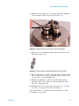
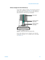
1
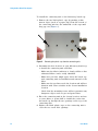
Agilent Gas Clean Filter
System
User Manual
Agilent Technologies
Notices
© Agilent Technologies, Inc. 2013
Warranty
No part of this manual may be reproduced
in any form or by any means (including
electronic storage and retrieval or
translation into a foreign language) without
prior agreement and written consent from
Agilent Technologies, Inc. as governed by
United States and international copyright
laws.
The material contained in this document
is provided “as is,” and is subject to being
changed, without notice, in future
editions. Further, to the maximum extent
permitted by applicable law, Agilent
disclaims all warranties, either express
or implied, with regard to this manual and
any information contained herein,
including but not limited to the implied
warranties of merchantability and fitness
for a particular purpose. Agilent shall not
be liable for errors or for incidental or
consequential damages in connection
with the furnishing, use, or performance
of this document or of any information
contained herein. Should Agilent and the
user have a separate written agreement
with warranty terms covering the
material in this document that conflict
with these terms, the warranty terms in
the separate agreement shall control.
Manual Part Number
5973-1528
Edition
Third edition, August 2013
Second edition, May 2013
First edition, August 2012
Printed in USA
Agilent Technologies, Inc.
2850 Centerville Road
Wilmington, DE 19808-1610 USA
Safety Notices
CAUTION
A CAUTION notice denotes a hazard. It
calls attention to an operating
procedure, practice, or the like that, if
not correctly performed or adhered to,
could result in damage to the product
or loss of important data. Do not
proceed beyond a CAUTION notice
until the indicated conditions are fully
understood and met.
WA R N I N G
A WARNING notice denotes a hazard.
It calls attention to an operating
procedure, practice, or the like that, if
not correctly performed or adhered to,
could result in personal injury or
death. Do not proceed beyond a
WARNING notice until the indicated
conditions are fully understood and
met.
Agilent Gas Clean Filter System
User Manual
Using the Gas Clean Filter System
About the Gas Clean Filter System 4
Components 4
Features 5
Filter types 5
Safety Information 9
General gas safety 9
Cleaning 9
Recycling the product 9
Installation 10
Before you begin 10
Prepare your instrument 10
Install the connecting unit 11
Connect the gas lines 23
Install the filter to the connecting unit 26
Install a two- or four-position connecting unit 37
Gas Flow in a Gas Clean Filter 39
Replacing the Gas Clean Filter 40
When to replace the Gas Clean Filter 40
To replace the Gas Clean Filter 42
Checking for Leaks 44
Indicator changes color from the top down 44
Indicator changes color from the bottom up 45
Replacement Parts 46
Agilent Technologies
3
Using the Gas Clean Filter System
About the Gas Clean Filter System
The Agilent Gas Clean Filter system delivers high purity
gases to your analytical instruments, reducing the risk of
column damage, sensitivity loss, and instrument downtime.
The filters are designed for use with the GC, GC/MS,
ICP- OES, ICP- MS, LC/MS, and any other analysis instrument
using carrier gas. Six filters are available, including CO2,
oxygen, moisture, and organics trap (charcoal).
Components
The Gas Clean Filter System consists of a connecting unit
and filter (Figure 1). The connecting unit is equipped with
inlet and outlet connectors for the gas lines, and two
needle- like valves that automatically start the flow of gas
once a filter is attached. The filters come filled with dry
nitrogen and are made from a heavy- walled polycarbonate
sealed at the base with PTFE. When installed onto the
connecting unit, the needle- like valves puncture the PTFE
seals and allow gas to flow through the filter.
Connecting unit
Filter
Outlet connector
Inlet connector
Figure 1
4
The components of the Gas Clean Filter System (connecting
units vary in appearance but perform the same functionality)
User Guide
Using the Gas Clean Filter System
Features
The Gas Clean Filter System delivers the following features
and benefits:
• Cleaner gas, longer instrument life, greater sensitivity,
higher data accuracy, and overall long- term stability for
your instruments and analyses.
• A high- flow connecting unit that handles flow rates up to
20 L/min for collision gas applications and supply gas for
ICP- MS, ICP- OES, and LC- MS.
• A fast- stabilizing and absorbent filter material.
• Filter housing constructed with a transparent and
virtually unbreakable, heavy- walled polycarbonate
material.
• The ability to change the Gas Clean Filter without tools
or gas shut- off.
Filter types
Each Gas Clean Filter type is designed to filter out a
specific impurity that may exist in the gas supply. The
following filter types are available:
• Carbon Dioxide - Eliminates CO2 from supply gas to the
Total Organic Carbon (TOC) analyzer, and improves
sensitivity and accuracy in TOC analysis.
• Oxygen - Prevents oxidation of the GC column, septum,
liner, and glass wool.
• Moisture - Delivers faster stabilization times for
increased GC productivity, and prevents hydrolization
damage to the stationary phase, column, liner, glass wool,
or septum in the GC.
• Process Moisture - Prevents oxidation of GC components
and is safe to use with acetylene in process GC
applications.
• Charcoal - Removes organic compounds and ensures
correct performance of FID detectors in the GC.
• GC/MS - Delivers faster stabilization times for increased
GC productivity, removes oxygen, moisture, and
hydrocarbons from the carrier gas for MS applications,
and provides ultimate GC column protection.
Table 1 on page 6 shows recommended filter connection
diagrams for common instrument configurations.
User Guide
5
Using the Gas Clean Filter System
Table 1
Connection diagrams for common detectors
Detector
ECD
Electron Capture Detector
Connection Diagram
Carrier Gas
Oxygen Filter
Moisture Filter
Nitrogen
Oxygen Filter
Moisture Filter
Column
Make-Up Gas
Anode Purge Gas
ECD
FID
Carrier Gas
Oxygen Filter
Hydrogen
Charcoal Filter
Air
Charcoal Filter
Carrier Gas
GC/MS Filter
Make-Up Gas
Charcoal Filter
Hydrogen
Charcoal Filter
Moisture Filter
Column
Flame Ionization Detector
(Carrier Gas = Make-Up Gas)
FID
FID
Column
Flame Ionization Detector
(Carrier Gas differs
from Make-Up Gas)
FID
FPD
Air
Charcoal Filter
Carrier Gas
Oxygen Filter
Hydrogen
Charcoal Filter
Moisture Filter
Column
Flame Photometric Detector
PFPD
Pulsed Flame Photometric
Detector
Air
Flame 1
Charcoal Filter
FPD
Flame 2
6
User Guide
Using the Gas Clean Filter System
Table 1
Connection diagrams for common detectors (continued)
Detector
MS (ITD, MSD)
Connection Diagram
Carrier Gas
GC/MS Filter
Column
Ion Trap Detector,
Mass Selective Detector
MS
Carrier Gas
Oxygen Filter
Moisture Filter
Column
MS
NPD, PND
Carrier Gas
Oxygen Filter
Moisture Filter
Column
Nitrogen-Phosphorous Detector
Make-Up Gas
TID, TSD
Hydrogen
Charcoal Filter
Air
Charcoal Filter
Carrier Gas
Oxygen Filter
Thermionic Detector
(Carrier Gas = Make-Up Gas)
TCD
TSD
Moisture Filter
Column
Thermal Conductivity Detector
Reference Channel
Make-Up Gas,
if necessary
User Guide
TCD
7
Using the Gas Clean Filter System
Table 1
Connection diagrams for common detectors (continued)
Detector
Connection Diagram
ICP-OES/ICP-MS
Oxygen Filter
Inductive Coupled
Plasma-Optical Emission
Spectrometry/-Mass
Spectrometry
Supply Gas
Oxygen Filter
ICP-MS
ICP-OES
(Plasma Gas = Nebulizer Gas)
ICP-OES
Inductive Coupled
Plasma-Optical Emission
Oxygen Filter
Supply Gas
ICP-OES
Oxygen Filter
(Different Optic Flush Gas)
High-Flow Base Plate
Optic Flush Gas
Total Organic Carbon (TOC)
Analyzer
Zero-Air Generator
Oxygen Filter
Carrier Gas
CO2 Filter
Moisture Filter
TOC Analyzer
Carrier Gas
CO2 Filter
Moisture Filter
Zero-Air Generator
LC/MS
Moisture Filter
Mass Spectrometry
LC/MS
Supply Gas
Moisture Filter
High-Flow Base Plate
Contact your local Agilent sales representative for the filter
sets applicable to your instrument configuration.
8
User Guide
Using the Gas Clean Filter System
Safety Information
General gas safety
• Wear eye protection when using compressed gas to avoid
eye injury.
• Fasten all compressed gas cylinders securely to an
immovable structure or permanent wall.
• Store and handle compressed gases in accordance with
relevant safety codes.
• Do not put gas cylinders in the path of a hot air vent
(including a GC oven exhaust).
• Perform periodic leak checks on supply lines, fittings, and
pneumatic plumbing to prevent a potentially hazardous
condition.
Cleaning
Wipe away dust and residue using a lint- free cloth.
Once the filter is consumed, the filter and filter material
cannot be replenished or reused.
Recycling the product
When filters are replaced, they must be treated as chemical
waste and disposed of according to local policy.
User Guide
9
Using the Gas Clean Filter System
Installation
Before you begin
Be sure to choose a centralized installation location where
all instruments are easily reachable and where the filter’s
indicating material is always visible.
Gas Clean Filter connecting units are available for both
1/4- inch and 1/8- inch gas lines. Be sure you have selected
the appropriate connecting unit to use with your lab setup.
Prepare your instrument
Prepare your instrument by doing the following:
1 Lower any heated zone temperatures on your instrument
to less than 100 °C.
2 Set any purge flows on your instrument to 400 mL/min.
3 If your system pressure is higher than 7 bar (100 psi),
reduce the pressure.
10
User Guide
Using the Gas Clean Filter System
Install the connecting unit
The connecting unit can be mounted on a laboratory bench
top, affixed to the wall (with optional wall- mounting bracket
for the single filter connecting unit), or mounted to the back
of a 7890 GC (with the Gas Clean Carrier Gas Kit for 7890).
• If you wish to install your connecting until to a
laboratory bench top, see “Installing on a laboratory
bench top” below.
• If you wish to install your connecting unit to a wall, skip
to “Installing on a wall” on page 13.
• If you have the Gas Clean Carrier Gas Kit for 7890
(CP17988) and wish to install the connecting unit to the
back of a 7890 GC, skip to “Installing the Gas Clean
Carrier Gas Kit for 7890” on page 20.
Installing on a laboratory bench top
You can install the connecting unit onto the laboratory
bench top using two screws (not supplied).
Gather the following:
• Screws (2), at least 25 mm long and less than 5- mm od
(not supplied)
• Screw driver or power drill
User Guide
11
Using the Gas Clean Filter System
To install the connecting unit to the laboratory bench top:
1 Remove the two black plastic caps by pushing a thin,
narrow object (such as a paper clip) from the bottom of
the connecting unit into the underside of the caps until
they pop out (Figure 2).
Figure 2
Removing the plastic caps from the connecting unit
2 Determine the best location on your laboratory bench top
to install the connecting unit and filter.
• Make sure the filter’s indicator is clearly visible so that
exhausted filters can be easily identified.
• Make sure you have ample space above the bench top
and connecting unit for installation and removal of the
filter.
• Make sure the gas lines reach the location and will not
interfere with other activities in the chosen installation
location.
• Check that the mounting screws will not penetrate any
dangerous objects such as gas and power lines.
3 Place the connecting unit in the chosen location, and use
a screw driver or power drill to install the screws into
the bench top through the two openings on the top of the
connecting unit.
4 Replace the black plastic caps on the connecting unit to
cover the two screw hole openings.
12
User Guide
Using the Gas Clean Filter System
Installing on a wall
This option is only available for a single filter connecting
unit using the optional wall mounting bracket.
Gather the following:
• Wall mounting bracket kit (CP7981)
• Flathead screw driver
• Hex wrench (4 mm)
• Power drill with 5- mm od drill bit
• Pencil
To install the wall mounting bracket:
1 Determine the location on the wall where you wish to
install the wall mounting bracket.
• Make sure you have ample space above the mounting
bracket with connecting unit installed for
installation/removal of the filter.
• Make sure the gas lines reach the location and will not
interfere with other activities in the chosen installation
location.
• Check that the mounting screws will not penetrate any
dangerous objects such as gas and power lines once
installed.
User Guide
13
Using the Gas Clean Filter System
2 Hold the wall mounting bracket against the wall in the
location that you plan to install it, and use a pencil to
mark the drilling location for the screw holes (Figure 3).
Figure 3
Mark the drilling locations on the wall using the screw holes in
the wall mounting bracket as a guide
Lay the mounting bracket down on a flat surface.
3 Using a power drill with a 5- mm od drill bit, drill about
5 cm into the wall in both locations. Wipe away any
excess dust and residue.
4 If required, install the supplied drywall anchors into the
drilled holes, and make sure each anchor is flush against
the wall’s edge (Figure 4).
Figure 4
14
Plastic drywall anchors installed in wall
User Guide
Using the Gas Clean Filter System
5 Hold the wall mounting bracket in place against the wall
using one hand, then use your other hand to install each
screw into the wall (or drywall anchor, Figure 5). Finger
tighten the screws as far as possible, and then use a
screwdriver to complete the screw installation. The wall
mounting bracket should rest flush against the wall.
Figure 5
User Guide
Installing the wall mounting bracket
15
Using the Gas Clean Filter System
6 The connecting unit supports gas connections on the base
plate edge for surface mounting and from below when
mounting the connecting unit against a wall. The
connecting unit ships from the factory with the gas
connections installed on the edge. In this step, the
standard connecting unit is shown. Steps are similar for
all connecting unit types.
You can optionally change the gas inlet- outlet locations to
the bottom of the connecting unit as follows:
a Using a 5- mm hex wrench, remove the two plugs on
the underside of the connecting unit (Figure 6).
Outlet fitting
Inlet fitting
Plugs
Figure 6
16
Plugs and inlet/outlet fittings on the connecting unit
User Guide
Using the Gas Clean Filter System
b Using a 1/2- inch wrench, remove the inlet and outlet
fittings on the end of the connecting unit (Figure 6).
c Install the plugs on the end of the connecting unit
using a 5- mm hex wrench (Figure 7).
Plugs
Figure 7
User Guide
Plugs installed on the end of the connecting unit
17
Using the Gas Clean Filter System
d Install the inlet and outlet fittings on the underside of
the connecting unit using a 1/2- inch wrench
(Figure 8).
Outlet fitting
Figure 8
18
Inlet fitting
Inlet and outlet fittings installed on the underside of the
connecting unit
User Guide
Using the Gas Clean Filter System
7 Install the connecting unit to the wall mounting bracket.
a Depending on the inlet/outlet fitting orientation on the
connecting unit, align the connecting unit to the
bracket as shown in Figure 9.
Figure 9
Connecting unit orientations on wall mounting bracket
b Using your hand, install the hex screws from the
bottom- up until they are finger tight (Figure 10).
Figure 10 Hex screws installed
c Use a 4- mm hex wrench to tighten the screws. The
connecting unit should be tight against the wall
mounting bracket.
User Guide
19
Using the Gas Clean Filter System
Installing the Gas Clean Carrier Gas Kit for 7890
Gather the following:
• T- 10 Torx driver
• T- 20 Torx driver
• Gas Clean Carrier Gas Kit for 7890 (CP17988)
To install the bracket and bracket connecting unit to the
back of a 7890 GC:
1 Place the bracket (5003- 1356) against the back of the
7890 GC in the location shown in Figure 11, then align
the screw holes as shown in Figure 12.
Figure 11 Location on back of 7890 GC to install bracket
Bracket
Screw holes
Figure 12 Screw hole locations on back of 7890 GC and bracket
20
User Guide
Using the Gas Clean Filter System
2 Using a T- 10 Torx driver, install the four T- 10 screws to
secure the bracket to the GC. See Figure 13.
Figure 13 Bracket 5003-1356 installed to 7890 GC
3 If you wish to run the inlet and outlet plugs from the
bottom of the bracket connecting unit, see step 6 on
page 16 before installing the bracket connecting unit to
the bracket.
User Guide
21
Using the Gas Clean Filter System
4 Install the bracket connecting unit to the bracket using
the supplied T- 20 Torx screws.
• If you have an ALS installed with your system, install
the bracket connecting unit to the top of the bracket
(Figure 14).
Figure 14 Bracket connecting unit installed on the bracket top for ALS
and general configurations
• If you have a PAL Auto Sampler installed with your
system, install the bracket connecting unit to the
underside of the bracket (Figure 15).
Figure 15 Bracket connecting unit installed on underside of bracket for
PAL Auto Sampler configuration
22
User Guide
Using the Gas Clean Filter System
Connect the gas lines
Before starting, make sure you have enough gas line tubing
to reach the area where you wish to mount the Gas Clean
Filter system. For best results, use pre- cleaned gas lines.
Gather the following:
• Swagelok nuts (included with the connecting unit
assembly)
• Front and back ferrules (included with the connecting
unit assembly)
• Wrench, 7/16- inch (for 1/8- inch nuts) or 9/16- inch (for
1/4- inch nuts)
• Pre- cleaned tubing
• Ball valve (0100- 2144), required for the Gas Clean Carrier
Gas Kit for 7890 (CP17988)
• Electronic leak detector, such as the Agilent G3388B
Handheld Electronic Gas Leak Detector
To connect the gas lines to the connecting unit:
1 Place a Swagelok nut, back ferrule, and front ferrule to
the tubing as shown in Figure 16.
Front ferrule
Back ferrule
Nut
Important!
The narrow end of the
back ferrule fits into
the rear of the front
ferrule.
Tubing
Figure 16 Swagelok nuts and ferrules
User Guide
23
Using the Gas Clean Filter System
2 Push the tubing towards the base until it rests firmly
against the shoulder in the fitting, and make sure that the
front ferrule is touching the fitting. Slide the Swagelok
nut over the ferrule and thread it onto the fitting
(Figure 17).
Nut and ferrules
Fitting
Tubing
Figure 17 Assemble the fitting
3 Push the tube fully into the fitting, then withdraw it
approximately 1 to 2 mm (see Figure 18).
Front
ferrule
Nut
Insert
tubing fully
Back
ferrule
Withdraw tubing
1-2 mm
Tighten nut
Figure 18 Insert the tubing
4 Finger- tighten the nut. Then use a wrench to tighten the
nut 3/4 turn (for 1/8- inch tubing).
24
User Guide
Using the Gas Clean Filter System
5 If you have the Gas Clean Carrier Gas Kit for 7890
(CP17988), install a ball valve immediately following the
outlet connection on the bracket connecting unit as shown
in Figure 19.
Outlet
Ball valve
Bracket connecting unit
Figure 19 Ball valve installed following the outlet connection on the
bracket connecting unit
A ball valve installation is optional for standard
connecting units.
6 Set the gas line pressure to a value between 2 bar
(30 psi) and 4 bar (60 psi) when installing the filter to
the connecting unit. Be sure to keep the pressure above
2 bar (30 psi) so that air does not enter the filter.
7 Check all connections for leaks using the leak detector.
User Guide
25
Using the Gas Clean Filter System
Install the filter to the connecting unit
CAUTION
Wear clean, lint-free gloves to prevent contamination of parts with
dirt and skin oils.
If you have the Gas Clean Carrier Gas Kit for 7890, skip to
“Bracket connecting unit” on page 31.
Standard connecting units
To install the filter on a standard connecting unit:
1 Unscrew the knurled ring and remove the red plastic dust
cap from the top of the connecting unit (Figure 20).
Red plastic dust cap
Knurled ring
Figure 20 Remove the red plastic dust cap
26
User Guide
Using the Gas Clean Filter System
2 Flush the gas line of oxygen and moisture.
If available, use the optional flush head (part number
CP7987) to flush the gas line (Figure 21). Place the flush
head over the valves and alignment pin and push down
until it rests on the base of the connecting unit. Install
the knurled ring to hold it in place.
Flush head
Figure 21 Using the flush head to flush the gas line of oxygen and
moisture
User Guide
27
Using the Gas Clean Filter System
If you do not have the flush head, use a small object or
your finger to depress the inlet valve. (The inlet valve has
an O- ring positioned at the top of the cylinder, as shown
in Figure 22.)
O-ring
O-ring
Inlet valve
Outlet valve
Figure 22 Depress the inlet valve to flush the gas line of oxygen and
moisture
Flush the gas lines for at least several minutes to ensure
the gas lines are free of oxygen and moisture.
28
User Guide
Using the Gas Clean Filter System
3 Remove the filter from the packaging, then remove the
two aluminum plugs from the bottom of the filter
(Figure 23).
Aluminum plugs
Figure 23 Remove the aluminum plugs from the filter
4 Place the knurled ring over the filter, then place the filter
on top of the connecting unit (it will only fit one way due
to the alignment pin shown in Figure 24). Be careful to
not damage the connecting unit and filter components by
forcing an incorrect filter orientation.
Alignment pin
Figure 24 Alignment pin
User Guide
29
Using the Gas Clean Filter System
5 Tighten the knurled ring while gently pressing down on
the filter. Let the knurled ring pull the filter onto the
connecting unit as it is tightened (Figure 25).
Knurled ring
Figure 25 Tighten the knurled ring to secure the filter to the connecting
unit
6 Allow the filter to pressurize for 3 minutes.
7 Flush the filter. Set the instrument split vent flow (purge
flow) to 400 mL/min, then:
• If using a Moisture Filter in combination with an
MS detector, purge the filter for at least 60 minutes.
This will flush the filter of dry nitrogen so that it does
not appear as a background ion in your MS analysis.
• For all other filter and detector combinations, purge
for 4 minutes.
8 Restore to normal operating supply pressure and method
settings. (Remember to keep at a minimum supply
pressure of 2 bar (30 psi).)
30
User Guide
Using the Gas Clean Filter System
Bracket connecting unit
To install the GC/MS filter on the Gas Clean Carrier Gas Kit
for 7890 bracket connecting unit:
1 Turn the ball valve to the on position.
2 Unscrew and remove the plastic ring nut from the top of
the bracket connecting unit (Figure 26).
Plastic ring nut
Bracket connecting unit
Figure 26 Remove the plastic ring nut from the bracket connecting unit
User Guide
31
Using the Gas Clean Filter System
3 Flush the gas line of oxygen and moisture.
If available, use the optional flush head (part number
CP7987) to flush the gas line (Figure 27). Place the flush
head over the valves and alignment pin and push down
until it rests on the base of the connecting unit. Install
the knurled ring to hold it in place.
Flush head
Ball valve on
Figure 27 Using the flush head to flush the gas line of oxygen and
moisture
32
User Guide
Using the Gas Clean Filter System
If you do not have the flush head, use a small object or
your finger to depress the inlet valve. (The inlet valve has
an O- ring positioned at the top of the cylinder, as shown
in Figure 28.)
O-ring
O-ring
Inlet valve
Outlet valve
Figure 28 Depress the inlet valve to flush the gas line of oxygen and
moisture
Flush the gas lines for at least several minutes to ensure
the gas lines are free of oxygen and moisture.
User Guide
33
Using the Gas Clean Filter System
4 Remove the GC/MS filter from the packaging, then remove
the two aluminum plugs from the bottom of the filter
(Figure 29).
Aluminum plugs
Figure 29 Remove the aluminum plugs from the GC/MS filter
5 Place the plastic ring nut over the GC/MS filter, then
place the filter on top of the bracket connecting unit (it
will only fit one way due to the alignment pin shown in
Figure 30). Be careful to not damage the bracket
connecting unit and filter components by forcing an
incorrect filter orientation.
Alignment pin
Figure 30 Alignment pin
34
User Guide
Using the Gas Clean Filter System
6 Tighten the plastic ring nut while gently pressing down on
the filter. Let the plastic ring nut pull the GC/MS filter
onto the bracket connecting unit as it is tightened
(Figure 31).
Figure 31 GC/MS filter installed to the bracket connecting unit
User Guide
35
Using the Gas Clean Filter System
7 Allow the GC/MS filter to pressurize for 3 minutes.
8 Flush the filter. Set the instrument split vent flow (purge
flow) to 400 mL/min, then:
• If using a Moisture Filter in combination with an
MS detector, purge the filter for at least 60 minutes.
This will flush the filter of dry nitrogen so that it does
not appear as a background ion in your MS analysis.
• For all other filter and detector combinations, purge
for 4 minutes.
9 Restore to normal operating supply pressure and method
settings. (Remember to keep at a minimum supply
pressure of 2 bar (30 psi).)
36
User Guide
Using the Gas Clean Filter System
Install a two- or four-position connecting unit
The steps for installing a two- or four- position connecting
unit are similar to the steps for the single- filter connecting
unit. Refer to the previous sections in this chapter for
details (“Installation” on page 10).
Two-position connecting unit
When installing the two- position connecting unit, refer to
Figure 32 for gas line and filter installation locations.
Oxygen
Moisture
Figure 32 Two-position connecting unit
User Guide
37
Using the Gas Clean Filter System
Four-position connecting unit
When installing the four- position connecting unit, refer to
Figure 33 and Figure 34 for common gas line and filter
configurations.
Instrument Air
In Out
Charcoal
Carrier Gas
In
Oxygen
Carrier Gas
Out
Moisture
Hydrogen
In Out
Charcoal
Figure 33 Configuration 1: Four-position connecting unit
Instrument Air
In Out
Carrier Gas
In Out
Hydrogen
In Out
Makeup Gas
In Out
Charcoal
GC/MS
Charcoal
Charcoal
Figure 34 Configuration 2: Four-position connecting unit
38
User Guide
Using the Gas Clean Filter System
Gas Flow in a Gas Clean Filter
Gas flows in an upward direction from the bottom of the
filter to the top, and then downward through the filter
material, indicating material, and out the bottom of the filter
(see Figure 35).
Filter material
Indicating material
Figure 35 Flow of gas through the Gas Clean Filter
User Guide
39
Using the Gas Clean Filter System
Replacing the Gas Clean Filter
When to replace the Gas Clean Filter
As gas passes through the filter material, the filter picks up
impurities and eventually becomes consumed over time.
When this occurs, an increased amount of impurities reach
the indicating material, which causes the material to change
color from the top- down.
When 75% or more of the indicating material’s color has
changed, this indicates that the filter is consumed (see
Figure 36).
Filter material
Indicating material
color change
Indicating material
original color
Figure 36 Indicating material color change
Agilent recommends replacing the filter when 75% or more
of the indicator’s color has changed (from the top down) or
within one year of installation.
40
User Guide
Using the Gas Clean Filter System
The indicator color and consumed indicator colors are
different for each type of filter. See Table 2 for a description
of each filter indicator color and consumed color change.
Table 2
Indicating material color description
Filter type
Original color
Consumed color
Oxygen Filter
Green
Gray
Moisture Filter/
Process Moisture Filter
Green
Pale brown
Charcoal Filter
No indicator
No indicator
GC/MS Filter
Oxygen: Green
Moisture: Green
Gray
Pale brown
CO2 Filter
White
Violet
See “To replace the Gas Clean Filter” on page 42 for more
information.
User Guide
41
Using the Gas Clean Filter System
To replace the Gas Clean Filter
This procedure shows the standard connecting unit in the
examples. Steps are similar for all connecting unit types.
To replace the Gas Clean Filter:
1 Lower any heated zone temperatures on your instrument
to less than 100 °C.
2 Set any split vent flows (purge flows) on your instrument
to 400 mL/min.
3 If your system pressure is higher than 7 bar (100 psi),
reduce the pressure to a pressure no lower than 2 bar
(30 psi) to ensure easy removal of the saturated filter.
4 Remove the saturated filter by unscrewing the knurled or
plastic ring nut that secures the filter to the connecting
unit (Figure 35).
Figure 37 Unscrew the knurled or plastic ring nut
5 Remove the new filter and O- rings from the packaging.
42
User Guide
Using the Gas Clean Filter System
6 Remove the old upper set of O- rings using the supplied
tool and replace with new O- rings (Figure 38).
Figure 38 Remove upper pair O-rings only when replacing filter
7 Remove the two aluminum plugs from the bottom of the
new filter (Figure 39).
Figure 39 Aluminum plugs removed from bottom of the new filter
8 Place the knurled or plastic ring nut over the filter, then
put the filter on top of the connecting unit (it will only fit
one way due to the alignment pin).
9 Tighten the knurled or plastic ring nut while gently
pressing down on the filter; let the ring pull the filter
onto the connecting unit.
10 Carefully check the connections for leaks. See “Checking
for Leaks” on page 44 for more information.
Treat used filters as chemical waste and dispose of them
according to local policy.
User Guide
43
Using the Gas Clean Filter System
Checking for Leaks
During leak- free operation, the filter indicator should not
change color for several months, depending on the quality of
your gas.
If you notice a color change in your filter’s indicating
material immediately following installation, this indicates a
gas leak in your system, or poor gas quality. Take note
whether the color change occurred from the top down or
from the bottom up, and refer to one of the following
sections:
• “Indicator changes color from the top down” on page 44
• “Indicator changes color from the bottom up” on page 45
Indicator changes color from the top down
If the indicating material changed color from the top down
(see Figure 40), there is a leak upstream of the filter in your
gas line, or your gas quality is poor. Check for leaks at the
cylinder, regulator, and fittings, and check your gas quality.
Filter material
Indicating material
color change
Indicating material
original color
Figure 40 Indicating a leak upstream from the filter
CAUTION
44
When about 75% of the indicator changes color from the top down,
this indicates that the entire filter is consumed and needs to be
replaced.
User Guide
Using the Gas Clean Filter System
Indicator changes color from the bottom up
If your filter’s indicator changes color from the bottom up
shortly after installation (see Figure 41), this indicates a
leak downstream of the filter in your gas line. Check for
leaks between the filter and your instrument.
Filter material
Indicating material
original color
Indicating material
color change
Figure 41 Indicating a leak downstream from the filter
If the entire indicator has not changed color (from the
bottom up), the filter is not consumed and is still usable
(see Figure 41).
User Guide
45
Using the Gas Clean Filter System
Replacement Parts
Table 3
46
Agilent Gas Clean Filter Starter Kits
Description
Part No.
Gas Clean Carrier Gas Kit for 7890
Includes GC/MS filter (CP17973), a 7890 GC mounting bracket,
and a single bracket connecting unit
CP17988
Agilent Gas Clean FID Filter kit
Includes a 4-position 1/8 in connecting unit and two Charcoal
filters, one Oxygen filter, and one Moisture filter
CP7995
Gas Clean Filter Kit, 1/8 in
Includes a 4-position 1/4 in connecting unit and two Charcoal
filters, one Oxygen filter, and one Moisture filter
CP736530
Agilent Gas Clean GC/MS Filter kit, 1/8 in
Includes a 1-position connecting unit 1/8 in and two GC/MS
filters
CP17976
Agilent Gas Clean GC/MS Filter kit, 1/4 in
Includes a 1-position connecting unit 1/4 in and two GC/MS
filters
CP17977
Agilent Gas Clean GC/MS Filter Installation kit
Includes 1 m copper tubing (CP17976), two nuts and two
ferrules, 1/8 in
CP17978
Agilent Gas Clean CO2 kit
Includes 2-position 1/4 in connecting unit and CO2 and
moisture filters
CP17982
Agilent Gas Clean CO2 kit
Includes 2-position 1/8 in connecting unit and CO2 and
moisture filters
CP17983
TCD Filter Kit
Includes a 2-position 1/8 in connecting unit, one Oxygen filter,
and one Moisture filter
CP738408
GC Installation Kit
Includes CP736530 and many useful fittings and accessories
19199N
User Guide
Using the Gas Clean Filter System
Table 4
Description
Part No.
1-position connecting unit, 1/4 in
CP7980
1-position connecting unit, 1/8 in
CP7988
2-position connecting unit, 1/4 in
CP738406
2-position connecting unit, 1/8 in
CP738407
4-position connecting unit, 1/4 in
CP7989
4-position connecting unit, 1/8 in
CP736520
High flow connecting unit, 1/4 in
CP17984
High flow connecting unit 1/8 in
CP17985
1-position stainless steel connecting unit, 1/4 in
CP7980P4
1-position stainless steel connecting unit, 1/8 in
CP7988P8
1-position stainless steel connecting unit, 3 mm
CP7988P3
1-position stainless steel connecting unit, 6 mm
CP7980P6
1-position 7890 GC bracket connecting unit
(for bracket 5003-1356)
CP742950
Table 5
User Guide
Connecting Units
Replacement Gas Clean Filters
Gas Clean Filters
Part No.
Agilent Gas Clean CO2 Filter
CP17969
Agilent Gas Clean Oxygen Filter
CP17970
Agilent Gas Clean Moisture Filter
CP17971
Agilent Gas Clean Process Moisture Filter
CP17971P
Agilent Gas Clean Charcoal Filter
CP17972
Agilent Gas Clean Filter GC-MS
CP17973
47
Using the Gas Clean Filter System
Table 6
48
Accessories and Fittings
Gas Clean Filters
Part No.
Wall mounting bracket for connecting units
CP7980 and CP7988
CP7981
7890 GC mounting bracket for bracket connecting unit
(CP742950)
5003-1356
Ring nut connecting unit
5043-0403
Flush head for connecting unit
CP7987
Male connector, 1/4 in with dust filter
CP7986
Male connector, 1/8 in.with dust filter
CP82117
O-rings, two sets
CP7983
Male connector, stainless steel, 1/4 in with dust filter
CP7986SS
Male connector, stainless steel, 1/8 in with dust filter
CP82117SS
Male connector, stainless steel, 3 mm with dust filter
CP82117SS3
Male connector, stainless steel, 6 mm with dust filter
CP7986SS6
User Guide
Agilent Technologies
© Agilent Technologies, Inc. 2013
*5973-1528*
5973-1528