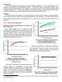
1
Primer on Flame Ionization Detectors by: Randall Bramston-Cook Lotus Consulting 5781 Campo Walk Long Beach, Ca 90803 310/569-0128 [email protected] June 4, 2011 Copyright 2011 Lotus Flower, Inc. Flame ionization detection (FID)1 is a primary mechanism for measuring organic compounds eluting from gas chromatographic columns. It is not as selective as other detectors (such as a thermionic specific detector - TSD, often called a nitrogen-phosphorus detector - NPD), but most organics will generate electrons from their combustion in a flame, and this process creates a signal related to the analyte concentration. Notable exceptions are carbon disulfide, carbon dioxide, carbon monoxide, and formaldehyde. Inorganic gases, such oxygen and nitrogen, do not produce significant responses with this detector, but huge amounts passed through can cause a disruption in the flame process and yield a very small response, especially when the bulk gas into the detector differs from the eluting bulk sample gas. This detector has extensive use in monitoring hydrocarbons in a variety of matrices, including gasoline, diesel, biodiesel, jet fuel, refinery gas, kerosene, crude oil, fuel oil, natural gas, liquefied petroleum gas, engine exhaust, and ambient air. Other applications include measurements of essential oils, alcohols, oxygenates, volatile free fatty acids, primary amines, antioxidants, phenols, polycyclic aromatic hydrocarbons (PAH), and residual solvents (especially in pharmaceutical products). Distinct advantages of this detector include: Huge number of detectable analytes. Insensitive to many bulk matrices, such as air, water, carbon dioxide, carbon monoxide, all inorganic gases (H2, O2, N2, Ar, He), and carbon disulfide. Extremely wide dynamic range, often exceeding capabilities of chromatography Low detection, typically less than 50 ppbV Methane The common flame employed with this detector in gas chromatography is a hydrogen diffusion flame, with no premixing of fuel and oxidant.2 Combustion takes place at the interface between hydrogen coming through the flame jet and oxygen available from a sheath of air around the flame. Typical fuel mixture travels at linear velocity approaching 1,300 cm/sec, whereas the oxidant flows at about 10 cm/sec.3 This outcome yields a very clean, stable and transparent flame with temperatures over 2,000 oC.4 Even though this combustion is very inefficient in generating electrons (estimated conversion around 0.0015%),5 electrometers used to process the currents generated are sensitive enough to detect these very low signals. The chemical processes occurring within the flame envelop are combinations of completing reactions. Sternberg, et al6, postulated conditions for production of ions as: “Dependent on the energy density in the ionization zone, which is determined by the composition, flow, and diffusion properties of the gases introduced into the flame, “Hydrogen atoms, oxygen atoms, hydroxyl and hydroperoxy radicals are continually produced in the reaction zone, “Sample molecules introduced into the flame undergo cracking and stripping reactions to form reactive hydrocarbon fragments… which diffuse back into the inner cone of the flame, “Chemi-ionization reactions are exothermic oxidation reactions occurring in the reaction zone between reactive hydrocarbon radicals and the excited molecules and radicals from the matrix flame.” 1 References to detector design and performance relate specifically to the Bruker/Varian 450-GC Gas Chromatograph with Firmware Version 3.03, and most also apply to the Bruker/Varian 430-GC and Varian 3800/3900 Gas Chromatographs. Older versions of 450-GC firmware may present subtle differences to what is discussed here. Generic comments are also valid for older Varian and other manufacturers’ detectors. 2 Early flame experiments employed carbon monoxide as the fuel, but were soon abandoned undoubtedly by the obvious toxic exposure of the fuel to the chromatographer. 3 J. C. Sternberg, W. S. Gallaway, D. T. L. Jones, “The Mechanism of Response of Flame Ionization Detectors”, N. Brenner. et al, ed., Gas Chromatography, Academic Press, New York, 1962, p. 249. 4 R. J. Reed, North America Combustion Handbook, Volume I, North America Mfg, Co., Cleveland, Oh, 1986, p. 10. 5 J. V. Hinshaw, “The Flame Ionization Detector”, LCGC North America, Vol 23, Issue 12, 2005, p. 25. 6 Sternberg, et al, Gas Chromatography, p. 265-266. Reactions involved in the burning process are listed by Sternberg, et al,7 including primary reactions, matrix reactions giving energetic intermediates, and ionizing reactions using excited components from the matrix, and are repeated in Table I. These authors also discussed results of experiments performed with differing carrier gases, variations in flow rates and inclusion of premixed oxygen with hydrogen fuel. Some of these experiments are reproduced here with modern detector designs and reported below, with some differing outcomes, undoubtedly due to improvements in detector design over the years. Table I. Chemical Reactions in Flame Ionization. Typical Primary Reactions 1. Cracking C2H6 2CH3 CH3COCH3 CH3 + CH3CO (CH3)2COH (CH3)2 – CH2 + H2O 2. Stripping H + C2H8 C2H7 + H2 OH + CH3 CH2 + H2O H + CH C + H2 E D C B Matrix Reactions in Hydrogen Flame H + OH H2O* H + O + M OH* + M O + O + M O2 * + M O + HO2 OH* + O2 A Possible Ionization Reactions CH2 + OH* CH2OH+ + e– CH + OH* CH2O+ + e– CHO+ + H + e– CH + O2* CHO2+ + e– CH + H2O* CH2OH+ + e– CHO+ + H2 + e– CH + CO* CHO+ + CO + e– C + OH* CHO+ + e– C + O2* CO2+ + e– C + H2O* CH2O+ + e– + – CCl + OH* CHO + Cl + – CCl + O2* CO2 + Cl CO2+ + Cl + e– CCl + H2O* CHO+ + HCl + e– M – reaction chaperone involved in adsorbing excess reaction energies, typically the inert carrier and make-up gas molecules. 7 8 Sternberg, et al, Gas Chromatography, p. 262. Sternberg, et al, Gas Chromatography, p. 251‐253. Figure 1. Zones involved with combustion processes in the flame ionization detector. The sample is preheated in the flame tip (A). The unburned gas emerges to form the inner cone (B). Higher temperatures at its outer boundary lead to partial pyrolysis, with free radical reactions from back diffusion of hydrogen atoms. These cracked fragments then enter the main reaction zone (C) where oxidizing fragments (O, O2, OH radicals and HO2 radicals) penetrate by inward diffusion of oxygen to accelerate cracking and stripping. This leads to highly exothermic oxidation reactions. Energy liberated in the oxidation reactions is retained primarily by the product molecules formed. Then this excess energy is released by ionization reactions in the form of electronic energy (D). Surrounding the flame is a sheath of oxygen-rich gas (E) with some diffusing into the flame cone to support combustion, and most propelling combustion products and inert gases out of the detector.8 I. Principles of Operation The flame is generated by burning hydrogen, supported with oxygen from air bathing the surroundings. Exit hole at the top of the flame jet requires inert support gas, usually the carrier gas, to keep the flame stable for best performance. If this column stream is not enough to accomplish sufficient flow, extra flow is provided through a make-up gas added to the column effluent right at the detector base. Hydrogen fuel is added in at this same location. Collector Probe 180 V Ignitor Probe Air Combustion of organic molecules by the flame Air H2 Make-up generates electrons that can be collected and Carrier processed through an electrometer to give a signal that yields the amount of that analyte passing through. A metal collector cylinder is placed just above the flame, and a bias voltage of typically 180 Volts DC is applied between the flame tip (cathode) and this collector (anode) to direct electrons for processing into this signal. Frequently, the signal from the collector probe is directed to a conventional electrometer to convert the current generated into a voltage for processing by a data system. This approach requires setting of the electrometer range to keep the voltage signal within span of the analog-to-digital converter for data computations, typically 0-1 Volt or 0-10 Volts. The Bruker 450-GC Gas Chromatograph, instead, processes the generated current from the detector directly into a number, bypassing the voltage translation, to permit coverage of the complete range of the detector without changing the full scale voltage range setting.9 The Bruker 450-GC does possess an ability to set the full scale range to allow voltage processing through a conventional analog-to-digital converter (ADC) or for recording devices that mandate a voltage signal. The available range settings are 9, 10, 11 and 12, to represent the exponent in 10-x Amperes/milliVolt.10 Range 9 is the least sensitive, and range 12 is the most sensitive, and the latter always should be set when using the direct conversion to digits for full range signal coverage equivalency from ±100 microVolts full scale to ±1000 Volts full scale [sic] with a Bruker Workstation. Flame ionization detector is a “mass-flow” detector, where the mass flux through it is what is detected, and its response is independent of analyte flow rate through the flame jet; the same electrons are generated whether passing through the detector slowly or quickly. As a result, its signal is not severely impacted by changes in flow and valve upsets. By contrast, a thermal conductivity detector is a “concentration” detector where its response is very dependent on flow rates through it; a slower flow allows the analyte to reside in the detector longer and hence yielding a bigger response. The thermal conductivity detector is very sensitive to changes in flow and requires special considerations with valved-systems, especially involving column switching and backflushing actions. A good performing flame ionization detector is a near-perfect carbon counter for hydrocarbons, including alkanes, alkenes and aromatics. Its response per molar concentration for propane, with three carbons, is half that of hexane, with six carbons. To allow direct correlation of differing hydrocarbons, molar concentration units, for example - ppmVolume, are converted into ppmCarbon, by multiplying the molar value by the number of carbon atoms in that analyte. An exception to this rule is the response of methane relative to the other hydrocarbons; methane gives an enhanced signal for its carbon content by typically 13% over the others. 9 R. Bramston-Cook, “Processing Very Tiny and Huge Monster Peaks in the Same Chromatogram”, Lotus Consulting, 2009, available on request from Lotus Consulting at [email protected]. 10 MilliVolt is included in this unit from the historical use of analog recorders that had a full scale span of 1 mV full scale. Many gas chromatographs, including the Bruker 450-GC, report peak signals in units of Volts to correspond to the output of the usual electrometer, while others use the original signal units of Amperes. The interconversion between the two depends on the range setting of the electrometer. At a range of 10-12 Amps/mV, microVolts is equivalent to femtoAmperes. Corresponding area units are microVolt-seconds and femtoAmpere-seconds; both are equivalent with a range of 10-12 Amps/mv. II. Construction of a Flame Ionization Detector The essence of the flame ionization detector design has remained virtually unchanged for four decades. Inclusion of solid-state electrometers with Junction Field-Effect Transistors (JFET)11, through the introduction of the Varian Model 1740 Moduline C in 1968, made this detector’s performance maxed out at its theoretical limit, with the electrometer no longer a noise contributor. Few such dramatic improvements have occurred since. With electrical currents as low as 10-15 Amperes capable of being measured, all efforts to insulate this signal from external influences must be employed. Ceramic insulators are used in four locations to ensure that generated electrons are fully directed to the collector and on to the electrometer without interference. The flame tip is electrically insulated with ceramics to eliminate any noise generated by voltage spikes and electrical disturbances on instrument chassis ground. The collector probe has gold-plated connectors to ensure accurate measure of extremely low currents generated in the detector. And this probe and associated collector cylinder are electrically isolated from the instrument with ceramic insulators as well. O-ring Seals (hidden) Collector Flame Tip Flame Tip Nut Ignitor Crunch Washer Flame Tip Washer Flame Tip Ferrule Column Oven - Detector Cross-over Figure 2. Cross-section of Flame Ionization Detector in the Bruker 450GC Gas Chromatograph Bruker flame tip designs have patented small exposed ceramic insulation at the jet exit to reduce interaction with analytes at this critical junction.12 Figure 3 illustrates the enhancements generated with use of this ceramic tip design over metal tips, run under identical conditions and scaling. Peaks for high molecular Metal weight hydrocarbons are about 5-10 times larger, and extend Flame Tip out to C-96. Also metal-clad columns for high temperature applications can be positioned just below the ceramic orifice to avoid danger of shorting out as expected with a metal tip and “to mitigate sample fragmentation from pyrolysis on the interior surfaces”.12 Ceramic Flame Tip Figure 3. Chromatograms of Polywax 655 with different tips.12 A graphite-Vespel ferrule (Bruker P/N CR213200 for detector temperatures to +400 oC), or graphite-only ferrule13 (Bruker P/N CR211200 to +450 oC) for very high temperature operations, provides a seal between this flame tip and its base. And a small washer is inserted between this ferrule and its nut to provide an unobstructed pathway for the air flow to be directed around the flame jet. 11 See discussions at en.wikipedia.org/wiki/JFET. Berg, J., Wells, G. “High Temperature Flame Jet for Gas Chromatography.” U.S. Patent 4 999 162, Mar. 12, 1991. 13 Graphite ferrules are very soft and pliable, and more likely to get stuck inside the detector base. The graphite/Vespel ones should be used whenever detector temperatures do not exceed the ferrules’ temperature limit of 400 oC. 12 To allow measurement of carrier and flame gases through the detector, an aluminum crunch washer (Bruker P/N 1500334701) at the base of the detector tower and silicone o-rings (Bruker P/N 390596004 each, or P/N 99775204 pkg/10) on the probes provide seals around the detector so that all flows are directed to the top of the tower to be monitored with a flowmeter. This crunch washer should be replaced every time the tower is removed for inspection or maintenance. A heater is installed in the detector base to prevent any condensation of material inside that would contaminate the detector and impact performance, and is separated from and usually higher than the column temperature. And an associated platinum (resistive temperature device - RTD) temperature probe is inserted nearby to monitor temperature at the base. The massive tower is in close contact with the detector base to keep its temperature near the setting and stable. Since the detector is capable of being maintained up to 450 oC, side arms off the tower are fashioned to keep electrical connections at the probe ends away from damaging heat. An ignitor is included with the bottom probe and is close to the tip to provide convenient lighting of the flame. The ignitor is automatically triggered whenever a method is activated, when a flame-out is sensed, or when the user selects the keyboard “ignite” button. The ignitor makes three attempts at lighting, and upon failure to confirm ignition, generates a fault and stops all instrument/workstation operations, with an indicated error message. If a fault occurs, it can be cleared by correcting the cause of the failure and reigniting the flame. A capillary column is inserted into the detector cross-over at the roof of the column oven and reaches almost to the top of the flame tip to maintain an inert surface through the detector bowels. This distance for the Bruker 450-GC and Varian 3800 is 9.5 cm from the bottom of the brass column nut to the tip of the column to be inserted.14 This cross-over specifically has low thermal mass to minimize transfer of heat from either zone to the other. Performance of this detector is very dependent on the geometry of the flame. The standard 0.02” flame tip orifice (Bruker P/N 200193800) is useful for most applications. All published specifications for the Bruker 450-GC Gas Chromatograph are based on this flame tip. When added detectivity is required, a narrower tip of 0.01” (Bruker P/N 200187500) can enhance peak sizes due to the tighter, hotter flame generated. However, this tip gives a bit more unstable flame and is more susceptible to flame-outs, especially with packed columns and valved systems. Special precautions with added flame-out restrictors are frequently needed to eliminate this issue. III. Even Response Factors for Hydrocarbons Accurate standards are often not available for every possible hydrocarbon found in samples.15 Reliance must be made on the uniform response of flame ionization detectors with hydrocarbons. Then, the response factor for a limited hydrocarbon set can be applied to all others measured with the same detector. Figure 4 illustrates the ability of high performance detectors to measure a wide range of hydrocarbons and still achieve even responses with the same detector. Then, for example, the response for Propane can be applied to all analytes measured near its elution, and Benzene for those around it and beyond, with confidence that correct concentrations for the full range of hydrocarbons are reported. 14 15 For older Varian gas chromatographs, including Varian 3700/3400/3600, this distance is 11.5 cm. For example, over 300 separate hydrocarbon species can be detected in engine exhaust and ambient air. +2 +2 -2% -2% Figure 4. High performance flame ionization detectors yield uniform response factors over a range of analytes, as demonstrated with a 100 ppbCarbon NIST custom hydrocarbon blend certified to ±2%. The discontinuity between two response factors is due to a switch in detectors, with differing flame tips sizes. IV. Special Applications Hydrogen Methane Volts Carbon Monoxide Nitrogen Oxygen Carbon Dioxide Flame Ionization Detector in Series with Thermal Conductivity or Photoionization Detectors Since the thermal conductivity or photoionization detectors do not destroy the character of analytes, either can be plumbed in series with the flame ionization detector to yield responses from both detectors on a single sample injection. Thus, for 2.0 example, inorganic gases, such as oxygen and nitrogen, can be measured together with hydrocarbons, especially hydrocarbons below detection by the thermal conductivity detector. Or aromatic and olefinic hydrocarbons can be picked out from other hydrocarbons with the photoionization and flame ionization detectors plumbed in series. Reduction Catalyst Conversion of Carbon Monoxide and Carbon Dioxide Carbon monoxide and carbon dioxide are not responsive to flame ionization, but can be measured after their conversion to methane with a reduction catalyst of nickel nitrate. The catalyst is heated to 380 o C and has continual flow of hydrogen (10 ml/min) to provide a reducing environment to effectively convert these two analytes into detectable methane. Detection is down to less than ppmV and is linear up into high percentage levels. TCD 0.0 FID 2 4 6 8 Minutes Figure 5. A flame ionization detector can be plumbed in-series with a thermal conductivity for simultaneous measurement of inorganic gases with TCD and hydrocarbons with FID. An included reduction catalyst allows carbon dioxide and carbon monoxide to be converted to methane for sensitive detection by FID. Total Hydrocarbons Rapid screening tests for hydrocarbons can be performed by injecting an aliquot of sample directly to the flame ionization detector without chromatography. The result is called Total Hydrocarbons (THC). Since this detector’s response is even across the range of non-methane hydrocarbons, the signal can be accurately quantified against a propane standard. V. Performance Specifications Noise Proper signal processing of the flame ionization detector with modern electrometers should generate detector responses that are limited only by noise generated from the combustion process at the flame, and not from the signal processing, notably from the electrometer. This noise then becomes the major limiting factor in how low concentrations can be measured. Classically, this noise value is assessed as the peak-to-peak variations over a reasonable time interval, typically a few minutes. Now, with data systems processing digital values for the signal, all sorts of signal averaging can be applied to yield any value desired for this noise value. For example, raw data collected at 100 Hz with Varian 450-GC could display some very noisy chromatograms and make sorting out legitimate peaks from baseline noise very difficult. To reduce high frequency noise without significant distortion of peak shapes, a digital 31-point Finite Impulse Response filter16 is applied to raw data points in the gas chromatograph during data collection. In addition, signal conversions can be averaged into “bunched” points to still properly describe the peak and allow more suppression of noise through this process. A Detector Bunch Point is an arithmetic average of the user-specified number of raw data points, and effectively changes the data collection rate. This point is then transmitted from the gas chromatograph to the Workstation. Peak-to-peak noise is readily determined by visually picking out the highest and lowest noise excursions and then taking the difference in microVolts or picoAmperes. Another approach to determining noise values is to compute the root-mean-square (RMS) value for noise over a time interval17 by: ∑ or one standard deviation from the mean, and where yi is each data point over the interval. The relationship between RMS noise and peak-to peak noise is usually considered to be a factor of 6, to include 99.7% of the excursions.18 Direct comparisons of noise characteristics among different detectors of the same style, especially differing brands, are impacted by the signal processing conditions, especially by analog dampening (with a resistor-capacitor network) and digital filtering applied to the detector signal. Any use of noise must always include conditions used to generate this value, especially ones with extreme averaging that can distort chromatographic peak shapes. Elevated background signals directly impact the level of noise with the flame ionization detector. High background signals can be generated from impurities in any of the supply gases, column bleed or heavy compounds from previous samples continuing to elute. In a clean system, noise is curiously related to the temperature of the detector, perhaps lowering diffusion rates of hydrogen and oxygen atoms within the flame cone from lower temperatures, as illustrated in Figures 6 and 7, and Table II. 16 See discussions on finite impulse response (FIR) by R. Bramston-Cook, “Peak Detection with Varian Star Workstation for Varian 3800 and 450-GC Gas Chromatographs”, Lotus Consulting, 2010, available on request from Lotus Consulting at [email protected]. 17 Peak-to-peak and RMS noise values can be calculated by “converting raw data to ASCII” with Bruker MSWS Software and then copying/pasting the data into Microsoft Excel. Peak-to-peak noise for a selected region is obtained with “MAX” and “MIN” functions, and RMS noise is determined with “STDEV” function. 18 M. Duff, Analog Devices, Inc., www.youtube.com/watch?v=-KcODSYXiZA, accessed June 4, 2011. Typically, the detector temperature is suggested to be set at +50 oC over the maximum temperature of the column oven, to ensure that all eluents are kept in the vapor state and do not condense in the detector.19 If column bleed is low and purities of supply gases are appropriate, low levels of analytes injected into the column are most likely to remain volatile well below their elution temperatures due to their vapor pressures at lower detector temperatures. However, if the elevated background signal from column bleed and impurities from supply gases are minimal, and detector noise generated is from the flame itself, this noise is related to the temperature of the detector base and tower.20 60 0 30 300 oC microVolts 30 0 250 oC 0 15 10 0 150 oC 10 0 100 oC 200 oC 0 0.0 2.0 4.0 Minutes Figure 6. Noise level on the detector is directly impacted by the temperature at its base. Data collection rate for all segments displayed is 12.5 Hz. If all column eluents have low boiling points, such as the hydrocarbon range from C1 through C8, then a lower detector temperature results in lower noise and improved detection limits and detectivity. With higher boilers, a simple recovery test with different temperatures can ensure that a lower temperature does not affect their responses. Realtive Peak‐to‐Peak Noise 350 oC 6.0 4.0 2.0 0.0 100 Detector Peak‐to‐ Root‐Mean‐ Flame Temperature Peak Noise Square Noise Background (oC) (µV) (µV) (mV) 100 12 1.8 1.08 150 14 2.2 1.17 200 22 3.4 1.29 250 33 4.6 1.64 300 43 6.8 2.15 350 60 9.3 2.63 150 200 250 300 o FID Base Temperature ( C) 350 Figure 7. A plot of relative peak-to-peak noise versus detector temperature illustrates the noise improvement with lower temperature settings. All noise levels are normalized to the level at 100 oC. Table II. Summary of impacts from different detector temperatures on noise levels. 19 Bruker Model 450-GC User Manual, Bruker Chemical and Applied Markets, Fremont, Ca, p. 262. Dependence of diffusion coefficients on temperature for gases can be expressed, using the Chapman-Enskog theory, by T3/2, where T is temperature in oK. Reference: en.wikipedia.org/wiki/Mass_diffusivity, accessed 5/23/11, 20 Drift Stability of the detector signal is critically important during measurements at or near detection limits. An unstable baseline can make peak detection at these levels difficult and erroneous. Drift can be generated from contamination anywhere in the chromatographic process, and needs to be minimized for best performance. Drift is differentiated from noise by a measure of the long term change in signal levels, rather than the higher frequency random noise. Figure 8 illustrates a typical drift over 30 minutes for the Bruker 450-GC flame ionization detector. A properly conditioned system should exhibit ≤ 10 microVolts/minute drift. Figure 8. Typical drift for a flame ionization detector in the Bruker 450-GC Gas Chromatograph. Raw data points (ASCII) are transferred into Excel to compute the trend line, showing a drift of 0.3 microVolts/minute from the slope of the line. Signal Amplitude Resolution The signal conversion process in the Bruker 450-GC can distinguish signal amplitudes at 1 microVolt resolution (equivalent to 1 femtoAmpere), as shown in Figure 9. This rate is fully adequate to define peaks and noise for the flame ionization detector under all measurement conditions. 4 uVolts 2 0 -2 -4 8.700 8.750 8.800 Minutes Figure 9. A magnified portion of the signal shown in Figure 7 illustrates the signal resolution of 1 microvolt for the Bruker 450-GC Flame Ionization Detector. Detectivity Detectivity is a measure of how low the detector can properly perceive hydrocarbons. Often this is simply a computation of the signal-to-noise ratio of a low concentration hydrocarbon analyte, and then extrapolated to a value of 2:1. However, the sharpness of the peak can greatly impact the amplitude of the signal, and the detectivity value. Since the measurement involves a flux through the flame tip, the better measure of detectivity is the minimum detectable quantity per second. This computation then normalizes out the influence of peak widths. Basing the calculation on peak-to-peak noise, peak response as peak area, and the limit as twice the noise level, detectivity can be computed by:21 Since noise is impacted by the data treatment applied to raw data, this specification must be listed with all measurement conditions employed, and the criteria used in the calculation. The published specification for the Bruker 450-GC flame ionization detector is a conservative 2 pgCarbon/sec. An actual measurement yields a value of: 800 uVolts Conventional units for detectivity are picogramsCarbon/ second (pg/sec). The analyte amount is converted to weight of carbon by means of multiplying the injected amount by the percentage of weight of carbon in the molecule. A lower value for detectivity implies a better performing detector. Propane ⁄ 0 4.0 \ 44 16 1,626 . 2 – / 4.2 4.4 4.6 Minutes Figure 10. Portion of 30 ppmV Propane Chromatogram with 1 µl injection. Detector temperature: 250 oC. Propane Conditions used for this measurement are: flame tip size - 0.02”, propane concentration - 30 ppmV, sample injection volume - 1.0 microliter, data bunch rate - 16 (6.3 Hz), propane retention time - 4.3 minutes, detector temperature: 250 oC, carrier gas - helium at 5 ml/min, and make-up gas - nitrogen at 25 ml/min. An equivalent measurement with the 0.01” tip results in a detectivity value of 0.58 picogramsCarbon/second. Detection Limit The concept of detection limit is related to detectivity, but it is computed differently. Here the result is a measure of how low an analyte can be measured with statistical significance. The whole measurement process is thus assessed, including injection volume repeatability, stability of the response of the detector, and random signal variations. The normal protocol involves measurement of at least seven identical, consecutive runs at or near the expected detection level, a calculation of three times the standard deviation of the areas from that series, and then dividing by the analyte response factor (peak area/concentration) to convert raw areas into concentration.22 21 uVolts 200 0 32.0 33.0 34.0 Minutes 35.0 Figure 11. Typical Propane peak generated from a 0.27 ppbCarbon standard and 300 ml loaded. A cryogenic concentrator reduced the sample volume to < 90 µl for on-column injection. Detector temperature: 250 oC. McNair, H. M., Bonnelli, E. J., Basic Gas Chromatography, Varian Associates, Palo Alto, Ca 1969, p. 87. US EPA, Compendium of Methods for the Determination of Toxic Compounds in Ambient Air, Second Edition, Compendium Method TO-15, January 1999, Section 11.2.2, p. 15-30. www.epa.gov/ttn/amtic/files/ambient/airtox/to-15r.pdf. 22 Raw Area Counts (µVolt-sec) ⁄ 3 872 823 225⁄3,019 926 943 0.07 ppbCarbon in 300 ml 873 or 10.3 pgCarbon 886 898 1074 Table III. Computation of Propane detection limit with a 0.27 ppbCarbon standard and 300 ml sample loading with nitrogen make-up. Sensitivity The term sensitivity, or detector response, is often incorrectly equated with detectivity. Sensitivity is a measure of how large a signal is generated by the flame ionization detector for a given concentration of analyte, or the slope of its calibration curve, normalized by the injection volume. Units for sensitivity become microVolt-sec/(ppbCarbon-ml) for gases, and milliVolt-sec/nanogram for liquid injections. Here a bigger number generates a better response. This parameter can be used to estimate the size of a peak for a given hydrocarbon. For example, the Bruker 450-GC Gas Chromatograph with a 0.02” flame tip generates a sensitivity of 6.27 microVolts-sec/(ppbCarbon-ml) for volatile hydrocarbons with nitrogen as the make-up gas. With an injection volume of 300 ml and a hydrocarbon concentration of 40 ppbCarbon, the expected peak area becomes 75,120 microvolt-sec. Typical sensitivity for the 0.01” tip is 9.4 microVolts-sec/(ppbCarbon-ml) for volatile hydrocarbons. For liquid injections into a capillary injector, sensitivity is usually > 33,000 milliVolt-sec/nanogram with helium as the make-up gas, and > 66,000 milliVolt-sec/nanogram with nitrogen make-up. Linear Range A clear advantage of the flame ionization detector over other chromatographic detectors is its ability to properly measure very low concentrations, typically around 50 ppbCarbon, as well as high percent levels, with near Figure 12. Cartesian plot of Area vs perfect linearity. Concentration, showing compression of points at low concentrations. Cartesian plots, as shown in Figure 12, display results nicely for limited concentration ranges typically within a factor of ten, but become congested at the low end when used for concentrations over multiple orders of magnitude, common with hydrocarbon measurements. This is a noticeable problem when the full range of the flame ionization detector - typically 107 - is displayed. To illustrate the full linear range, a more meaningful display is to plot Response Factor23 versus log[Concentration], as depicted in Figure 13. Thus, maintenance of linearity can be visualized clearly at both low and high ends of the range, and a defined tolerance (frequently specified as ±10%) indicated across the range. Propane Benzene +10% +10% ‐10% ‐10% Figure 13. Plots of Response factor vs log[Concentration] for Propane and Benzene permit better visualization of conformity to linearity over a wider range, including error bars for deviations at ±10%. Dynamic Range Dynamic range can be defined as the complete range of the detector where changes in concentration still effect a variation in signal, but outside the linear range. Typically, non-linearity occurs when the detector is severely overloaded and cannot readily distinguish increasing concentrations; a calibration curve then reaches an upper plateau. Some analytes can exhibit nonlinearity at the lower end of the scale due to component loss from active sites in the measurement system. Measurements can be made into these stages, but must be labeled as outside linearity. VI. FID Linear Range Outperforms Chromatography Chromatographic operating conditions are always a compromise between resolution of peaks, speed of analysis, and sample capacity. Parameters can be selected to achieve optimum performance for any one of these, or a compromise with selection of any two, but performance for the others are severely compromised. For example, best resolution of peaks is achieved with a long, narrow-bore, thin film capillary column with low carrier flow rates of nitrogen, but speed and sample capacity are severely compromised under these conditions. Fast chromatography requires short, thin-film columns and high flow of hydrogen, whereas sample capacity (or how much sample can be loaded onto the sample) needs wide-bore, thick-film columns with moderate flow rates. Optimum conditions for resolution or speed will cause peaks to be readily overloaded and thus skew the calibration curve’s linearity. Chromatographic conditions often cannot use the full linear range of the flame ionization detector, but having this capability provides assurances that the detector does not become the limiting factor. Other variables can dramatically impact linearity, including accurate standard preparations over the complete range, reactive sites in the sampling process and chromatographic system, especially in the injector module and column, and maintenance of appropriate loading into the column without overcapacity. With the exceedingly wide linear range for the flame ionization detector, its performance does not usually contribute to issues involving non-linearity of the experiment, from fast narrow-bore capillary to high-capacity packed columns; other factors are likely to be the culprit. 23 Response factor is area counts divided by concentration of that calibration point. VII. Bruker 450-GC Instrument Method Parameters for Flame Ionization Detector Most parameters for the flame ionization detector can be set and conditions monitored through both the instrument screen and Workstation. Both the touch screen on the Bruker 450-GC and Workstation are active until the instrument goes into run mode to collect data. Once a run starts, most parameters cannot be altered in real time, until the run ends. Flame ionization detector conditions and programming on the instrument are accessed through the “detector” icon on the right side of the screen. Figure 14. Detector Parameters are accessed through this icon on the Figure 15. Bruker 450-GC Screen Display keyboard of the Bruker for Flame Ionization Detector 450-GC Several parameters displayed are live updates of current operating conditions. The colored dots to the right side of the screen indicate the status of these components: • A green dot designates the component is “Ready”. • A yellow dot indicates the component is “Not Ready”, particularly the detector temperature or flow rates. • An empty dot stipulates the component is switched off by an unchecked “Enable”. • A red dot signifies the component is in “ERROR”, including flame-out, or failure to reach the set temperature or detector flow setpoints. Precise errors can be viewed though clicking on “Log” at the bottom right of the screen. Actual Temperature Temperature at the detector base is displayed and updated in real-time. If this temperature is outside ± 4.0 oC of the set point, the “not ready” yellow dot is illuminated until the tolerance is reached. If the temperature does not make any progress toward the setpoint, the system faults out “red” with all temperature zones in the instrument shutting down. Only rebooting the system, after the deficiency is corrected, clears the fault. Signal The live flame ionization detector signal is always displayed here and is impacted by the activation of any auto-zeroing action. Flame ignition can be confirmed when the signal shows some variations. Background of the detector, used for diagnostics, can be viewed with “Clear Autoz” button at the bottom of the screen. EFC Type 11 Actual24 Gas flows to the flame ionization detector are displayed as “Actual”. If this value does not match the setpoint, the status light in the area will display yellow to convey a problem, and the instrument will remain in “equilibrating”. 24 This parameter does not apply to the manual control option for detector gases. User Settable Parameters: Enable For active use of the flame ionization detector, this box must be checked, or all parameters are ignored and the system will proceed even when actual detector conditions do not match setpoints. The detector oven is also disabled. With Workstation operations, this parameter is labeled as “Detector Oven”. Electronics Functional use of the detector mandates that the electronics must be “enabled”. If this box is unchecked, then the output signal is maintained at zero, and flame-out sensing is disabled. If the Detector EFC is installed and not enabled, this box is grayed out and cannot be turned on. Temperature Setpoint for the detector temperature at its base is assigned here. This temperature setting can range from 50.0 oC to 450.0 oC, unless a lower maximum temperature is entered in Setup. The choice of temperature does have impact on noise, and needs to be warm enough to keep analytes, water and column bleed from contaminating the detector innards. The detector “ready” status is triggered when the actual temperature is within ±4.0 oC, and the actual temperature settles at typically less than ±0.2 o C, especially after a 2 minute stabilization interval. The actual temperature of the detector must exceed +100 oC for the ignitor to be enabled, to prevent accumulation of water in the detector. CAUTION - the ferrule sealing in the flame tip has an upper temperature limit depending on the material of the ferrule. Brown Vespel ferrules have an upper limit of 350 oC, dull black Graphite/Vespel ones (standard) have a 400 oC limit and soft shiny black ferrules allow the maximum limit of 450 oC, but are often difficult to extract out of the detector base intact. This limit can be user-fixed appropriately in Setup Detector. Figure 16. FID temperature limit is set in Setup Detector. Flameout Threshold The Bruker 450-GC constantly monitors the flame signal to ensure that the flame remains lit through the chromatographic process. If the raw signal, without zeroing, is detected below this threshold, a flame condition is considered as “out” and operations are halted until corrected. Very clean systems can generate very low baseline signals where a false “flameout” is sensed. This parameter can then be lowered to allow these low flame backgrounds to preclude the error, but still maintain monitoring of a lit flame. Check for Flame-out in Detector Setup Some detectors utilize the FID electrometer to process signals through the Bruker 450-GC, including photoionization detectors (PID) and pulsed discharge detectors (PDD). These detectors do not have a flame, per se, and need not have the built-in flame-out sensor active, especially when a fault is triggered by very low backgrounds often generated by these detectors. In Setup Detector, the check for flame-out can be disabled for that detector zone. Figure 17. Enabling check for Flame-out is chosen in Setup Detector. Time Constant This parameter is displayed, but has no role in data processing in 450-GC Firmware Version 1.07 and later. Now all dampening is performed digitally by adjustment of data collection bunch rates from the Workstation.25 Detector EFC Enable26 For active operations of flows to the detectors with a Detector Electronic Flow Controller (DEFC), the “Enable” box must be checked. If unchecked, the system will not wait for flows to match setpoints, and the associated electronics are automatically disabled. This parameter cannot be set through Workstation, and method downloads from Workstation will not impact this setting. Detector EFC Set26 The operator can set detector flows through the entries for Make-up, Hydrogen and Air with the inboard Detector Electronic Flow Controller (DEFC). These values then adjust flows to the detector. If actual flows do not match their setpoints, the status light nearby will indicate a fault condition. Upper range and tolerance for each gas are listed below. Detector Gas Flow Range (ml/min) Flow Rate Accuracy Ready Tolerance (ml/min) Actual vs Setpoint Make-up 0-55 ± 10% ± 1.0 < ± 0.2 Hydrogen 0-50 ± 10% ± 3.0 < ± 0.2 Air 0-550 ± 10% ± 1.0 < ± 0.2 Make-up Gas Label26 The choice of make-up gas affects the calibration of the Detector Electronic Flow Controller by the thermal conductivity of the gas and must be specified in Setup Detector. This entry is then displayed in all associated detector screens. If hydrogen is used for reduction catalyst feed as EFC11 Make-up, then helium is selected and desired flow must be measured with a separate flow meter and the setpoint adjusted to the desired hydrogen flow rate. Figure 18. Gas employed as make-up is specified in Setup Detector. FID/TSD Detector Full Scale The Bruker 450-GC flame ionization detector has the ability to handle signals from 100 microVolts full scale up to 1000 Volts full scale without need to change detector ranges.27 Unfortunately, the preset parameter to activate this mode is set to 10 V, and should be changed to 1000 V for the appropriate detector position in the Workstation method. 25 Figure 19. Workstation entry for Detector Full Scale of 1000 Volts. See discussions on detector time constant by R. Bramston-Cook, “Peak Detection with Varian Star Workstation for Varian 3800 and 450-GC Gas Chromatographs”, Lotus Consulting, 2010, p. 12, available on request from Lotus Consulting at [email protected]. 26 These parameters do not apply to manual controls of detector gases. 27 R. Bramston-Cook, “Processing Very Tiny and Huge Monster Peaks in the Same Chromatogram”, Lotus Consulting, 2009, available on request from Lotus Consulting at [email protected]. Time Programmable Parameters: Several detector settings are time-programmable to permit changes in operating range and to execute an automatic zeroing of the signal at user-selectable points in the chromatogram. Initial programming must be set prior to start of data collection, but additions can be made for times after the current progress time. Range Amplitudes of the chromatographic peaks are directly impacted by this range setting. The Bruker 450-GC has the ability to set the full scale range to allow voltage processing through a conventional analog-to-digital converter (ADC) or for recording devices that mandate a voltage signal. The range settings are 9, 10, 11 and 12, to represent the exponent in 10-x Amperes/milliVolt.28 Range 9 is the least sensitive, and range 12 is the most sensitive. Range can be time-programmed to keep various sized peaks on scale over the chromatogram, especially with analog recorders. With a Bruker Workstation connected directly to the Bruker 450-GC, the range setting always should be set to 12 to enable detection of peaks from low microVolts to kilovolts with this single range setting. Autoz Zeroing of the detector can be preprogrammed at specific times during the developing chromatogram to bring the signal back to zero. Appropriate times for this action are at the start of every run and at severe disruptions in the baseline that can occur with valve actions and column switching, among other events. Figure 20. Parameter entries for flame ionization detector from MS Workstation method. Active Bruker 450-GC Display Screen Buttons Three buttons on the detector display of the Bruker 450-GC allow the user to perform specific actions related to the signal. These are always active when the detector is enabled, even during a chromatographic run. Ignite Flame ignition is attempted whenever a method is activated, when flame-out is sensed, or manually by the operator using this button on the screen. The process makes three attempts to light the flame. If ignition is confirmed, the ignition steps cease. If the flame is not validated, an error message is triggered. The error can be cleared by either manually reattempting ignition, or by “un-enabling” the detector. Figure 21. Active buttons in detector section of Bruker 450-GC. 28 MilliVolt is included in this unit from the historical use of analog recorders that had a span of 1 mV full scale. Clear Autoz The natural background signal of the flame ionization detector is a useful assessment of the condition of the detector (see discussions below). This button clears the imposed zeroing of the signal and allows the raw signal to be displayed. All actions with use of this button impact the data collected during a run. If Autoz is enabled in the detector section of the method, Clear Autoz becomes momentary and reverts back after a few seconds to the zeroed signal. Autozero This button allows the operator to manually trigger an Autozero action during a chromatographic run to counter excessive drift in the signal, especially after valve actuations. All actions involving use of this button impact the data collected during a run, with sharp excursions to zero at the point of activation. Realative Area Counts Effects of Detector Gas Flows on Peak Size, for 0.02” Flame Tip Inert gases added into the flame tip with hydrogen aids in enhancing the combustion process and increasing peak sizes. A study of varying flows over the range of 20 to 50 ml/min for helium, nitrogen, and argon shows that argon provides the best sensitivity, and a flow of 50 ml/min boosts the response to the maximum level.29 Relative Area Counts 1.00 VIII. Operating Conditions Argon Nitrogen 0.67 0.33 Helium 0.00 15 20 25 30 35 40 45 Make‐up Flow (ml/min) 50 55 Figure 22. Changes in response with different make-up gases and various flow rates, with 0.02” tip 1.00 0.67 Maximum peak size is achieved with hydrogen flows between 30 and 35 ml/min with 50 ml/min argon make-up. Similar profiles for hydrogen are realized with the other make-up gases. 0.33 0.00 20 25 30 35 Hydrogen Flow (ml/min) 40 45 Figure 23. Relative peak sizes versus hydrogen flow in the detector, with 0.02” tip Flow rates for air flowing around the flame have minimal effects on performance of the flame ionization detector over the wide range of 200 to 400 ml/min. A flow rate of 300 ml/min is suggested to ensure that combustion products are adequately swept out to greatly minimize possible contamination inside the detector. 1.00 Relative Area Counts 15 0.67 0.33 0.00 150 200 250 300 350 Air Flow (ml/min) 400 Figure 24. Changes in peak size versus air flow in the detector, with 0.02” tip 29 Carrier gas flow for all experiments is 3 ml/min Helium. Minor changes from this carrier setting will not greatly alter these optimum points. Signal enhancements with nitrogen and Molar Heat Thermal Make-up Relative argon, over helium or hydrogen as make-up Capacity Conductivity Diffusion31 Gas gases, are attributable to differences in (J/mol K)30 (W/m K)32 physical properties of the gases. Lower 28.8 1 0.1805 Hydrogen diffusion and lower conductivities for argon 20.8 0.5 0.1513 Helium and nitrogen lead to a tighter, hotter flame, 29.1 0.27 0.02583 Nitrogen with a higher average molecular energy in 20.8 0.22 0.01772 Argon the reaction zone.33 The lowest thermal conductivity and diffusion of argon generates Table IV. Physical Properties of Make-up Gases. a higher temperature at the flame tip and slower equilibration of the liberated energy from the flame reactions over the other gases. These actions result in its higher sensitivity. Heat capacities for all listed carrier gases are nearly the same and have marginal impact on performance, compared to the other properties. For the same reason that argon and nitrogen provide enhanced signals for the flame ionization detector with their lower diffusion, they are not commonly employed as carrier gases for capillary columns. The analyte exchange between the stationary and mobile phases of the column system is critically dependent on the relative diffusion of the carrier, and peak shape is dramatically altered with these gases due to their resistance to mass transfer, compared with helium, or even better with hydrogen. Relative Response Addition of Internal Oxygen Most modern flame ionization detectors now employ a true hydrogen diffusion flame, with only hydrogen and inert gases flowing through the flame tip. When small amounts of oxygen are added at this point, along with carrier and make-up gases, a smaller inner cone develops in the flame just above the tip. Heat generated during this process leads to more thermal cracking, but the loss in fuel in the inner cone and pre-oxidation of analyte molecules reduces the response to combustion in the outer layers of the flame.34 Even with this limited combustion, the inner cone (B from Figure 1) retains its hydrogen diffusion character, but this area is altered by the decrease in available fuel and a buildup of combustion products from the premixed oxygen/hydrogen flame. Possible enhancements with the addition of internal oxygen are very compound dependent, with the higher inner flame temperatures and the presence of more reactive hydrogen atoms yielding bigger signals for selected analytes, notably for methane. This boost lessens for higher alkanes, where oxidation occurs more readily to cancel the enhancements from cracking and stripping. A notable example of this degradation is carbon tetrachloride, where it generates a response at about half of methane in a normal hydrogen-diffusion flame, but virtually 130% disappears with addition of internal oxygen, due to the 120% ease of preoxidation of the C-Cl bond, and absence of 35 detector response to the newly formed C-O bond. 110% 100% If methane and carbon dioxide/carbon monoxide (converted to methane with a reduction catalyst) are 90% the only components to be measured, then this 0 20 40 Internal Air Flow (ml/min) addition of internal oxygen (40 ml/min) can improve Figure 25. Relative enhancements to performance of the detector by about 20%. Other analytes will yield a lower response, with some Methane response, with addition of air into the make-up flow (balance N2 for total generating no response. 50 ml/min) to the flame ionization detector. 30 31 32 33 34 35 Source: http://www.wolframalpha.com/input/?i=heat+capacity+of+helium Computed from Graham’s Law, See http://en.wikipedia.org/wiki/Graham%27s_law, accessed May 22, 2011. Source: http://www.wolframalpha.com/input/?i=thermal+conductivity+helium, accessed May 22, 2011. Sternberg, et al, Gas Chromatography, p. 257. Sternberg, et al, Gas Chromatography, p. 253. Sternberg, et al, Gas Chromatography, p. 260. Relatove Area Counts 1.00 0.01” Tip 0.02” Tip 0.67 0.33 0.00 5 10 15 20 25 30 35 40 45 Argon Make‐up (ml/min) Relatove Area Counts Effects of Flame Jet Size on Sensitivity A smaller flame orifice (0.01” ID) creates a tighter flame profile that produces a hotter flame. This generates somewhat different response to hydrocarbons than its 0.02” brother, as illustrated in Figure 26. Optimum flows for this tip are also different than for the wider one. Due its flame geometry, this tip is more susceptible to flame-out from high flow rates, from large solvent injections and from pressure surges generated by valve operations, such as column switching with backflush to detector. Use of this tip is recommended only to achieve ultimate performance in detection limits and sensitivities. 0.67 0.33 0.00 200 300 Air Flow (ml/min) 400 Figure 28. Changes in peak size versus air flow in the detector, with 0.01” tip. Nitrogen Helium 0.33 0.00 5 10 15 20 25 30 35 40 45 50 Make‐up (ml/min) Figure 27. Changes in response with different make-up gases and various flow rates, with 0.01” tip Realtive Area Counts Relative Area Counts 1.00 Argon 0.67 50 Figure 26. Relative responses for 0.01” and 0.02” tips over a range of make-up flows. 100 1.00 1.00 0.67 0.33 0.00 5 10 15 20 25 30 35 Hydrogen Flow (ml/min) 40 45 Figure 29. Relative peak sizes versus hydrogen flow in the detector, with 0.01” tip. Effect of Bunch Rate on Noise Digital averaging of the signal occurs in two separate functions within the Bruker 450-GC. To avoid excessive noise, especially at high data rates, a 31-point Finite Impulse Response (FIR) filter36 is deployed during the initial signal processing and not adjustable by the user. Further noise suppression is performed through user selection of the data rate by choice of the Detector Bunch Rate in the Workstation. Here the Bruker 450-GC executes a simple averaging of the unprocessed data (after treatment by FIR Figure 30. Signal averaging is set through Detector Bunch Rate filtering) at 100 Hz to produce the specified data rate. Noise from the Workstation. is reduced somewhat by this action, but does not correlate with expected decreases. For example, a change from 100 Hz to 0.8 Hz should yield a noise reduction of 100⁄0.8, or a factor of 11, but only a drop of 3.2 is noted. Certainly, FIR filtering suppresses noise very effectively with the higher data rates without impacting peak shapes. 36 Discussions of Finite Impulse Response filtering can be found in R. Bramston-Cook, “Peak Detection with Varian Star Workstation for Varian 3800 and 450-GC Gas Chromatographs”, 2010, available on request from Lotus Consulting at [email protected]. 20 uVolts 0 -20 Data Rate = 100 Hz Data Rate = 50 Hz Noisep-p =48 Noisep-p =56 NoiseRMS=7.3 NoiseRMS=6.1 Data Rate = 25 Hz Data Rate = 12.5 HzData Rate = 6.3 Hz Noisep-p =44 Noisep-p =38 Noisep-p =35 NoiseRMS=5.5 NoiseRMS=4.8 NoiseRMS=4.4 Data Rate = 3.1 Hz Noisep-p =28 NoiseRMS=4.1 Data Rate = 1.6 Hz Data Rate = 0.8 Hz Noisep-p =24 Noisep-p =17 NoiseRMS=3.1 NoiseRMS=2.4 -40 5 0 10 15 20 25 30 35 Minutes 40 Figure 31. Detector noise at various data rates is shown over 5 minute intervals to illustrate the suppression of random noise through selection of the Detector Bunch Rate in the Workstation. Detector temperature: 250 oC. IX. Summary of Optimum Parameters For the 0.02” flame tip, maximum response is generated with these flame parameters: Make-up Gas Make-up Flow H2 Flow Air Flow Argon 40 ml/min 35 ml/min 300 ml/min For the 0.01” flame tip, maximum response is generated with these flame parameters: X. Make-up Gas Make-up Flow H2 Flow Air Flow Argon 20 ml/min 25 ml/min 300 ml/min Troubleshooting The flame ionization detector is undoubtedly a simple detector to diagnose problems, as it is not very complicated, compared to other chromatographic detectors, especially chem-illuminesence, Hall electrolytic-conductivity and pulsed flame photometric detectors. Flame Ignition Flame ignition is attempted whenever a method is activated, when flame-out is sensed by the instrument, or manually by the operator using the “Ignite” button on the screen. The ignition process makes three attempts to light the flame. If ignition is confirmed by the system, then the process is terminated, and normal operations are allowed to proceed. If not, a fault is triggered and operations are halted. After correcting the issue and reinitiating the ignition process with the “Ignite” button in the Detector section of the Bruker 450-GC, the error is cleared. After ignition is confirmed, an automatic 60 second delay is initiated to help recover from the ignition process before the system displays “ready”. Ignite FID No FID Auto Ignite Electronics On? Yes Signal > Flameout Threshold? No In “Setup” check flameout is ON? Yes Detector EFC is Ready? No No No No Yes Actual FID temperature is o > 100 C? Yes Ignite FID attempts > 3? Yes Alert Error 15, 16, or 17 End Yes Actual temperature o ±4 C? Yes Time Delay 60 sec FID Ready No Figure 32. Flowchart for automatic process of flame ignition. Confirmation of Flame Ignition Available means to sense for a functioning flame are: Instrument sensing background signal; “flame-out” error message not displayed Soft audible “pop” sound on ignition Water vapor on shiny cool surface above detector Peaks detected on chromatogram Signal background greater than 300 µV; activating “Clear Autoz” displays background Visible inspection for a flame is not possible with transparent hydrogen/oxygen flame Do NOT use alcohol-soaked Q-tip inside detector to verify Failure to Ignite Flame Reasons for the flame not to light include: Wrong flow rates Ignitor broken - carefully peek at glow inside the detector tower during ignition to confirm Loose flame tip Column not attached Column installed too far up into flame tip Facilitating Ignition Some settings for flame gas flows can make ignition difficult to accomplish. A temporary reduction of air flow from the keyboard of the chromatograph during the ignition process can enrich the flame gases enough to light the flame. This problem can be a particular troublesome issue with the narrow flame tip (0.01”) and relatively high flows needed to attain maximum performance. Once the flame is lit, it usually remains until the fuel and oxidant flows are removed, or the flame lifts off from the tip from high flows or flow surges, especially from valve actuations. Flame-Out During a Run Occasionally, the flame may be extinguished in the middle of a run. This problem is rare, as flow perturbations prior to the head of the column often are dampened out by the restriction through the column bore. The error message “Not Ready in Run” is displayed until the fault is corrected, typically through the automatic reignition process. The trouble is usually correlated with loss of supply gases or some valve event, especially when valving is configured after the column. To minimize this interruption, a flame-out restrictor fashioned from a short piece of narrow-bore tubing (0.18 mm ID), or for packed columns, 0.05” narrow-bore stainless steel tubing can be installed just prior to the detector. Although more common when packed columns were in wide use, massive injections of solvent, especially water, can extinguish the flame. In this case, a smaller injection loading is needed to reduce the solvent pulse through the detector, either by reducing the syringe volume or increasing the injector split ratio. This fault is spotted through an error displayed in the Bruker 450-GC Log and also by three high voltage spikes (+10 Volts) in the chromatogram, indicating attempts to relight it. If the flame fails to light, a fatal error is triggered, the active run is immediately halted, along with subsequent automated operations, and the current run data is lost. Validation of Flows Detector gas flows have a major impact on the performance of the detector. Whether flows for the supply gases are set with a detector electronic flow controller (DEFC) or with manual needle valves, flow rates ought to be confirmed with a digital flow meter (Bruker P/N 190011500) to validate detector flow settings. Since four separate flows all converge in the detector, make-up, hydrogen and air are initially all turned off, so only column flow is measured at the top of the detector using flow tube (P/N 200187600) inserted in the large silicone stopper (P/N 394958600) with a flow meter. Then make-up is turned on and the combined carrier and make-up are measured. Then hydrogen is added in and verified, and finally air is joined in and confirmed. The air measuring plug (P/N 1600050500) can be installed in Figure 33. Flows at the detector place of the flame tip assembly to be able to measure only air, can be measured by inserting a while all others are blocked. With a capillary column installed, flow tube and stopper at the top the column must be lowered a bit, as this plug will not fit with the of the detector tower. column penetrating into where the plug will be placed. This obstruction can also be used to pressurize the column system to test for leaks. A caution here is that, if hydrogen and make-up are flowing with tank pressures below the carrier pressure, blocked flow at the detector can back up into these streams, and the leak test never realizes the steady maximum pressure expected. Instead, the hydrogen and make-up settings must be set to zero to prohibit this backflow. Flows into the detector can be assessed by measuring total flows with the flame lit. Since air and hydrogen are burned to produce water, volumetric flow is reduced when the flame is active. Established total flow conditions can be monitored for overall flow with the flame lit to become the recognized benchmark. Differing readings indicate inappropriate flow settings. Also, a loud pop on flame ignition is indicative of either excessive hydrogen or inadequate air flow. Figure 34. Air Measuring Plug. Background Signal Condition of the complete detector can be gauged through monitoring of the detector background signal. To view this level, Autoz needs to be turned off, and the Clear Zero button manually triggered in the Detector section on the Bruker 450-GC screen. A low level indicates a clean detector and good purity of the gas sources. Typically levels range between 1 and 5 mV, and up to 10 mV are tolerable. A level approaching 100 mV indicates severe contamination. This signal should be continuously monitored over an extended time interval to note if the level is decreasing, implying a reduction in contamination, or is increasing, showing that the detector needs a bit more cleansing with heat, or replacement of suspected dirty parts or gases. If extreme temperatures are needed to be used here, especially exceeding the maximum allowable setting for the column, the column ought to be removed and its connection point suitably plugged. Contamination High background signals from contamination can directly impact the ability to measure low levels, as noise is increased. These impurities can mask desired peaks eluting from the column. A dirty detector can be triggered by a number of factors, including impure supply gases, dirty gas lines into the instrument, fingerprints on internal parts, column bleed, and condensation of high boiling compounds or combustion products from previously injected analytes. Even unexpected late elution of compounds from earlier runs can be generating elevated backgrounds. Continually monitoring of the background signal over time can provide an indication if the condition is improving with a declining signal. Often during bake-out, the signal will rise and then eventually start falling and then finally stabilize, hopefully at a low value. If the signal does not drop to an optimum level discussed above, then the background must be coming from a constant source, such as impurities in detector gases or column bleed. Insertion of hydrocarbon filters on carrier, hydrogen and make-up gases can dramatically reduce this source of background. All tubing from the supply tanks to the instrument must be chromatographic grade stainless steel (Supelco P/N 20526-U, tel 800/247-6628) or copper, and NEITHER “refrigerator” grade from a hardware store (as this tubing is full of oil to keep the copper “shiny” look), NOR plastic tubing of any sort (they readily release monomers and plasticizers, and often are permeable to oxygen and water from room air) should be installed. If either dirty tubing or plastic tubing is utilized, even for a short duration, contamination from them can penetrate into the system pneumatics and necessitate wholesale replacement of all tubing and pneumatic components, including injectors, valves, and even columns, to return the detector to its perfect state. Noise Excessive detector noise severely impacts the ability to measure low level analytes. Typical expected noise levels for good performing detectors are illustrated in Section V above. Frequent causes for high noise are due to excessive background levels from contamination. Conditioning the system at elevated temperatures often reduces this effect. Consistent spikes from external sources can appear in an irregular pattern to look like noise. All instrument covers should be installed during normal operations to assist in shielding the detector and signal processing from possible radiofrequency interferences, including cell phones, electric motors, and solenoids. 1 800 mVolts mVolts 0 -1 -2 0 -3 4.0 5.0 6.0 Minutes Figure 35. External electrical interferences, especially radio transmitters, can cause severe disruptions in the FID signal, and must be isolated away from the instrument. 0.4 0.6 0.8 1.0 Minutes Figure 36. Electrometer noise generated from an active Dremel rotary tool close to the signal cable. 4 2 mVolts Spikes Dramatic excursions in signal can greatly impact quantitation by artificially splitting peaks up and adding in extraneous areas. These spikes can be generated by mechanical vibrations, electric motors, proximate transmissions from cell phones, an unbalanced column oven fan37, unstable flame from improper flows, flame tip partially plugged, and particles from columns, especially packed columns and porous layer open tubular (PLOT) capillary columns. A special particle trap (Bruker P/N CP4018) can be inserted after a problem column and before the detector, to reduce the effects of these column crumbs. 0 -2 -4 1.6 1.6 1.7 Minutes Although the flame ionization detector is not very flow sensitive, occasionally pressure pulsations from single-stage regulators on supply Figure 37. Noise gases can generate regular patterns on the chromatogram, appearing produced from an active as spikes. Dual-stage regulators provide extra dampening of the outlet cell phone near flow and should be used on all gas supply tanks. A dual-stage regulator detector cabling. is distinguished from single-stage one by a protrusion on its backside to hold the second stage diaphragm; single-stage have a flat backside. Both have two gauges - one for the tank pressure and the other for the outlet and they are not distinguishable in this manner. Also, dual-stage regulators are less prone to increase outlet pressures as the tank depletes, and thus give no change in flows at the detector as the tank pressure depletes. Drift A drifting baseline can dramatically impact the quality of peak processing, especially proper allocations of areas or heights. For ultimate detector performance, the detector temperature and lit flame should be allowed to stabilize for at least an hour before making runs. Ultimate constancy is frequently achieved only after extended standby conditions above operating temperatures, often overnight. The baseline should be monitored with an expanded ordinate scale to match Figure 8. Column Bleed Many capillary columns now are better constructed to significantly minimize column bleed into the detector, especially ones labeled for mass spectrometric applications. However, some phases can generate significant bleed, especially polar ones, especially as the column oven temperature approaches the column maximum. To avoid detector contamination from the column phase, the column ought to be removed from the detector during the initial column conditioning while the column is heated toward its upper limit, and then later reinserted into the detector. This effect can be negated by executing baseline subtraction operations with the workstation. No Peaks or Smaller Peaks than Expected Absence of flame noise and signal background is an indication that the flame is out, the electrometer is not turned on (refer to diagnoses above), or a detector cable is detached. Numerous causes for no detected peaks or suppressed sizes also can be attributed to sampling and chromatography issues beyond the scope of this discussion. Missing peaks or smaller peaks due to the detector can be caused by a loose flame tip, a wider flame tip than expected, incorrect detector gas flows, or wrong detector electrometer range. A remote possibility is an electronic failure of the electrometer. An easy test to validate a functioning electrometer is to simply wiggle the signal cable and watch for a response on the signal display, as this mechanical perturbation always generates a response on the electrometer. 37 Trouble with an unbalanced fan motor can be confirmed by turning off the column oven heater and fan from the Bruker 450-GC keyboard and observing any change in audible and detector noise. Stuck in “Equilibrating” Whenever an instrument parameter is not at its setpoint, the system indicates that it is “equilibrating” and will wait until all setpoints are reached. With the flame ionization detector, the areas to look for problems reaching the compulsory settings can involve its base temperature and detector flows, when using the Detector Electronic Flow Controllers. The precise cause for the system not coming “Ready” can be viewed from the Status Page on the Bruker 450-GC keyboard. Remember that the detector has an automatic one minute hold after ignition, and will show “Equilibrating” during this wait. XI. Maintenance Since raw signals from the flame ionization detector are measured into the femtoAmpere range (10 Amperes), all components involved must be kept exceptionally clean, and all gas supplies need to be the best available, and especially free of residual hydrocarbons. Installation of hydrocarbon filters (Bruker P/N CP17972) on all gas supplies can help insure maintenance of the required purity. -15 Titanium Flame Tip Nut Older Varian detectors used chrome-plated brass nuts to hold the flame tip in place. They were very prone to coming loose, even when held at constant temperature. Several years ago, these were replaced with ones made from titanium (P/N 1600078500). With more compatible thermal expansion with other materials in the detector, these nuts are less likely to loosen. Titanium nuts are distinguishable from brass by a more machined appearance to the surfaces, including sharper corners and sometimes subtle visible machining grooves on the edge planes. Chrome-plated brass ones have more rounded corners and a very smooth-looking surface. When the flame tip is reinstalled, this nut must be snug enough to prevent gas flows from escaping through the associated ferrule, but not overly tightened to cause the interior ferrule to crack or deform. Insulators Electrical insulators are deployed in four locations in the Bruker 450-GC flame ionization detector to insulate the electric field between the cathode (flame tip) and anode (collector tube) from current leakage. White ceramics are used to isolate the tip of the flame jet, to position the collector tube in place, and to hold the probes in place. Overall performance of the detector is critically dependent on the cleanliness of these ceramic pieces. They must remain in their pristine condition, and the white parts should not be touched by the operator with anything but cotton gloves [McMaster-Carr P/N 9729T11 (large)/T12 (medium), tel 562/692-5911]. Oil from fingers on the ceramics becomes extremely difficult to remove, even with heat. Often, contaminated parts are easier to replace with new ones, instead of attempting to clean them. Ceramic in Signal Probe Ceramic holding Collector Tube Ceramic in Flame Tip Ceramic in Ignitor Probe Figure 38. Location of Ceramics in Tower Flame Tip The flame tip assembly in the Bruker 450-GC is comprised of a ceramic tip, stainless steel detector base, titanium nut, and usually a graphite/Vespel ferrule. They all have differing thermal expansion coefficients. Repeated heating and cooling of the detector cause the various parts to act together in loosening up the flame tip nut. To avoid catastrophic failure in the performance of the detector, the flame tip should be checked monthly for snugness. A 3/8” hollow-shaft nut driver (McMaster-Carr, P/N 8358A27, tel -562/692-5911) is the best tool to ensure that the nut is properly tightened. Cracked/Burned Ferrule in Flame Tip Difficulty in lighting the flame and degradation in detector sensitivity are often caused by a deteriorating ferrule holding the flame tip in place. A crack here will allow hydrogen and make-up gases to flow around the flame tip, instead of properly through its orifice. Then this leak can ignite and start burning up the ferrule to further degrade performance. This ferrule should be inspected regularly to catch this fault, and replaced if defective (Bruker P/N CR213200). Sealed Detector The Bruker flame ionization detector is sealed at all connections with an aluminum crunch washer at the base of the tower and silicone o-rings on both probes, except for the open vent at its top. This permits accurate measure of gas flows at the top of the detector with the appropriate adapters included with every instrument (flow tube, P/N 200187600 and large stopper, P/N 394958600). The crunch washer (Bruker P/N 1500334701) must be replaced whenever the tower is removed for inspection of servicing. The o-rings (Bruker P/N 9775204) should be exchanged when cuts and abrasions are observed. Applying Anti-seize on Tower Screws The detector base is constructed of stainless steel to keep its shape intact under stresses encountered. Screws holding the tower to its base are also stainless steel for added strength during tightening. Invariably, stainless steel screws in stainless steel receptacles tend to seize by galling and can make subsequent removal of the tower extremely difficult. To avoid this, antiseize lubricant (McMaster-Carr P/N 1367K91, tel -562/692-5911) can be applied only once to the very tip of the long screws used to clamp down the tower. Extreme caution must be exercised to avoid any possibility that the lubricant is applied to any area in the detector that could possibly reach the active flame zone. Removal and Reinsertion of Probes The ignitor probe has two prongs that are in contact with the flame tip metal sheath to polarize the tip. Before the tower is to be removed, this lower probe must be disengaged from the tip by pulling the ignitor a bit out of its position, to avoid distorting the prong shape during servicing. The upper signal probe can remain in place, unless the collector needs to be extracted for inspection or replacement. As the probes are pulled out, their red silicone o-rings will come into view, Figure 39. Probes are lined up with tabs and notches on their sides indicating that the probes have been pulled out far enough. during insertion. If these o-rings exhibit scrapes or gouges, they should be replaced. After detector servicing, these probes need to be reinserted into the tower. To maintain proper orientation with the flame tip or collector, each probe has a tab on one side to line up with the matching notch on the side of the tower side arm. To ease the o-rings into position, the probe can be rotated slightly, but must come into final alignment when approaching the ultimate spot. Brass Capillary Nuts Bruker intentionally uses brass ferrules for sealing columns to the detector to avoid seizing of the nut to the cross-over.38 Several chromatography supply houses promote a stainless steel version as a preferred substitute for this brass one, but the potential for galling of stainless/stainless connections or cross-threading of the fitting with its mate can result in damage to the detector crossover and could mandate an expensive replacement of the detector base. The brass version is strongly suggested for normal operations, and a special stainless steel version (P/N CP743117) is available for very high temperature detector operations - above 350 oC.38 38 Bruker recently introduced this special stainless steel nut (P/N CP743117) for very high temperature applications where the detector temperature is maintained above 350 oC, but is not recommended for normal applications below these temperatures, due to a chance for galling or cross-threading. Purity of Gas Supplies Hydrocarbons impurities in any supply gas can be major contributors to degradation in performance of the flame ionization detector. Even a purity of 99.995%, commonly labeled as “chromatographic” grade, can possess 50 ppmV hydrocarbons and still pass this specification. Ultimate performance is achieved with 99.9999% purity, often labeled as “research” grade. In-line hydrocarbons filters (Bruker P/N 392594492 each, with connecting unit) for carrier, make-up and hydrogen are recommended to aid in reducing contaminates further. Column Insertion into Detector Crossover Optimum performance is aided by keeping the pathway inside the detector inert up to the exit into the flame. Obviously, an inherently inert surface is the capillary column employed. By inserting the column up into the detector and just below the orifice of the flame tip, the analytes can avoid the reactive surfaces inside the detector. This magical distance is 9.5 cm41 from the end of the column to the bottom of the column nut. A convenient marker for this position is a small strip of tape that remains attached during installation but can be removed readily without leaving a trace, or use of GC Column Scale (P/N 392575001). Note that the ferrule in this nut is reversed from normal, to present a flat seal at the detector crossover, for easier subsequent removal. 9.5 cm Packed Column Installation The crossover connection for attachment of columns to the detector inside the column oven is designed specifically for capillary columns and requires an adaption for use with packed columns. To minimize detrimental effects of unswept deadvolumes at this critical point, a Valco reducer union for 1/8” packed columns (Valco P/N ZRU21C39, tel 800-367-8424), a fused silica adapter (Valco P/N FS1.8 for megabore columns) and a short section (typically 1 meter) of megabore (0.53mm ID) capillary column40, long enough to stretch from the end of the packed column into the detector, can be combined to provide the connection. Gas Connections into Detector Electronic Flow Controller Module Electronic flow controller (Type 11) for this detector allows the operator to set flows either from the Bruker 450-GC front keyboard/screen or from the Workstation. The chromatograph then establishes the actual flows to agree with the setpoints, and then documents Air IN M/U IN H2 IN flows in the run log of the Workstation. Attachment of gas lines are shown in Figure 40. Usually H2 OUT and M/U OUT are combined by a manifold into a single outlet connection. With connection to a reduction catalyst, two hydrogen flows are needed - one at 10 ml/min through the catalyst and the second at 20 ml/min - to provide a total flow of 30 ml/min to the detector. This manifold can be inverted to provide a single input of hydrogen into both hydrogen and make-up controllers, and then two outlets for the catalyst. The 450-GC Setup does not list H2 as a possible choice for M/U gas; instead “He” is selected and actual flow measured with an external flowmeter and the parameter adjusted to get the desired flow. M/U OUT H2 OUT Air OUT Figure 40. Gas connections into Detector Electronic Flow Controller Type 11. 39 For ¼” packed columns, this Valco adaptor is P/N ZRU41C. Any megabore column, or narrower, is appropriate here as its effect on chromatography is overwhelmed by the packed column. 41 Varian Model 3400/3600/3700/6000 Gas Chromatographs are configured for a distance of 11.5 cm from the bottom of the nut to the tip of the column that goes into the detector. 40 XII. Summary of Performance Data for Bruker 450-GC Gas Chromatogram RMS Noise Published Specification for Bruker 450-GC Typical Performance for Bruker 450-GC ≤ 7.5 microvolts < 4.6 microVolts (10 Hz data rate) (12.5 Hz data rate) Drift ≤ 10 microVolts/minute (12.5 Hz data rate) 0.3 microVolts/minute Flame on for > 1 hour Signal Range ±100 microVolts to ±1,000 Volts, full scale Amplitude Resolution 1 microVolt 1 femtoAmpere 0.87 pgC/sec Detectivity (0.02” flame tip) ≤ 2 pgC/sec 0.56 pgC/sec (0.01” flame tip) 10.3 pgCarbon Detection Limit (0.07 ppbC w/300ml) > 3,300 µV-sec/ng Single Range of 10 Amperes/mv > 6,600 µV-sec/ng (Nitrogen make-up) 6.27 µV-sec/(ppbC-ml) (0.02” flame tip) 9.4 µV-sec/(ppbC-ml) (0.01” flame tip) Range - 12 30 ppmV Propane, 1 µl injection, N2 make-up, p-p S/N: 2, 6.3 Hz, o detector - 250 C 0.27 ppbC Propane, 300 ml load w/Cryotrapping, o detector - 250 C Gas Injection 40 ppbCarbon, 300 ml load, N2 make-up 107 Linear Range -12 Liquid injection 1 µl C16 30 ng/µl, splitless, 0.02” flame tip (Helium make-up) Sensitivity RMS Noise (5 minutes), o detector - 250 C Peak-to-Peak (5 minutes), o detector - 250 C < 33 microVolts Peak-to-Peak Noise Measurement Conditions ±5% Flame Tip Patented Ceramic Orifice, 0.02” and 0.01”, isolated from chassis ground Flame-out Automatic Sensor and Reignition Attempts, with fault on failure Temperature Sensor Platinum Probe (Resistive Temperature Device - RTD) Temperature Range 50 - 450 oC Temperature Resolution for Setpoint and Display 0.1 oC « ± 0.2 oC Temperature Stability Detector EFC Controllers Detector EFC Accuracy Detector EFC Stability After 2 minute stabilization True Mass Flow Controllers for all flame gases ± 10% Typically < ± 0.2 ml/min XIII. Part Numbers for Bruker 450-GC Flame Ionization Detector 1. FID Field Kit with Type 11 Detector Electronic Flow Controller (DEFC), P/N 452100101F (120 VAC), P/N 452100102F (230 VAC), 16 P/N 452100103F (101 VAC) 14 2. DEFC Module (FID) Type 11 SI P/N CP74101180 15 3. FID Field Kit with Manual Pneumatics, 17 12 P/N 452100901F (120 VAC) P/N 452100902F (230 VAC) 13 P/N 452100903F (101 VAC) 15 4. Valve, Combo, Black, Air, 0-500 ml/min 11 (for manual control), P/N 391706500 5. Valve, Combo, Red, Hydrogen + Make-up, 0-50 ml/min (for manual controls), P/N 391706501 10 6. Valve, Combo, Blue, 0-150 ml/min (for manual controls), P/N 391706503 21 7. FID Electrometer, P/N 392502101 8. Analog out Cable to non-Bruker Workstation, 9-pin D-Shell 22 P/N 392567201 9. Analog out Cable to non-Bruker Workstation, spade connectors P/N 392567501 10. Detector Tower Body, P/N 100099300 11. Ignitor Probe, P/N 200187200 26 12. Signal cable, P/N 391783000 13. Ignitor cable, P/N 392548701 14. Signal Probe, P/N 200187300 15. O-rings, silicone, for probes, P/N 390596004 each, or P/N 9775204 pkg/10 16. Collector Tube, P/N 394958700 17. Collector Tube Insulator, P/N 2100003200 18. Screws, 8-32 x ¼”, P/N 1214200804 19. Screw, Microseal, 8-32 x 3”, P/N 391866302 Uncoated, 8-32 x 3”, P/N 391866301 20. Tower Top Plate, P/N 3400073100 21. Flame Tip Assembly, with washer and ferrule,42 0.02"ID, P/N 200193800 0.01"ID, P/N 200187500 22. Flame Tip Ferrule, 10/pkg Vespel (100%) max. 350°C, P/N CR212200 Graphite/Vespel 40/60 max. 400°C, P/N CR213200 Graphite (100%) max. 450°C, P/N CR211200 23. Flame Tip Nut, titanium, P/N 1600078500 24. Tower Seal (aluminum crunch washer), pkg/25, P/N 1500334701 25. Detector Base, P/N 392547501 18 19 20 23 24 25 27 42 Distinguishing the two flame tip sizes is not easy, but comparing the two by looking down the center axis of the tip can provide an assessment of the differences, with the 0.01” tip being obviously smaller. 6. Column Ferrules, pkg/10 350 oC CR2121XX 40% Graphite/ 60% Vespel 400 oC CR2131XX 450 oC CR2112XX -CR214104 CR214105 CR214108 CR212103 CR212104 CR212105 CR212108 CR213103 CR213104 CR213105 CR213108 -CR211104 CR211105 CR211108 --- -CP212222 CR213124 CR213125 -CR211125 Column ID Teflon Vespel Max Temp No-Hole 250 oC -- Single-Hole 0.18 mm 0.25 mm 0.32 mm 0.53 mm Two-Hole 0.25 mm 0.32 mm 27. Column Nut. 0.9 mm bore, brass, P/N 39495510043 28. Column Nut, 1.6 mm bore, brass, P/N CP742351 29. Column Nut, 0.9 mm bore, stainless steel for high temperature applications (350-450 oC), 2/pkg, P/N CP743117 30. Temperature Probe, P/N 392537401 31. Heater, 120V 125W- P/N 392539601 230V 125W- P/N 392539602 101V 125W- P/N 392539603 32. Flow Tube, P/N 200187600 33. Large Stopper, P/N 394958600 Air Measuring Plug 34. Air Measuring Plug, P/N 1600050500 35. Flowmeter, P/N 190011500 36. Detector Flow Measuring Kit (includes flow tube, large stopper, air measuring plug and flowmeter, P/N 391725091 37. Leak Detector, P/N CP87610 Graphite Flow Tube and Large Stopper 38. GC Column Scale, P/N 392575001 39. GC Column Scale Kit (includes scale, 2 nuts, 2 ferrules each for 0.4, 0.5 and 0.8 mm ID), GC Column Scale P/N 392575190 40. FID Test Sample Capillary column, 30 ng/µl C14, C15, C16 in isooctane, P/N 8200504807 Packed Columns, 300 ng/µl C14, C15, C16 in isooctane, P/N 8200504800 41. Column Particle Trap, 2.5 meters, 0.53 mm ID, P/N CP4017 42. Hydrocarbon Filter, P/N CP17972 43. Single Filter Connecting Unit, 1/8” fittings, P/N CP7988 44. Dual Filter Connecting Unit, 1/8” fittings, P/N CP738407 45. Quad Filter Connecting Unit, 1/8” fittings, P/N CP736520 43 The latest version of this column nut has a reduced opening to prevent ferrules from protruding through when tightened, and will not accommodate 1/16” tubing nor two columns inserted into a two-hole ferrule. If a nut with a wider hole is not available, then the narrow one can be drilled out with a 1/16” bit to provide adequate clearance, or the 1.6 mm bore version (P/N CP742351) can be substituted. Postscript: In my literature search for studies on the chemistry of the flame ionization process, I encountered a complete treatise of the topic in an early publication by J. C. Sternberg, W. S. Gallaway and D. T. L. Jones (“The Mechanism of Response of Flame Ionization Detectors”, N. Brenner. et al, ed., Gas Chromatography, Academic Press, New York, 1962) that provides a basis for much of the theoretical discussions in this monograph. Since the original text, from 1962, is not readily accessible today, portions of their manuscript are paraphrased or quoted directly here, to pass along their contributions to the science that still apply today. This author thanks Ed Nygren, James Pachlhofer, Rand Mahoney, Wilco Hoogerwerf, Jos Curvers, Paul Van den Engel, Hans van den Heuvel, and Nijsse Kees of Bruker CAM, Jack Marrin of Scott-Marrin, Inc., and Herb Neumann for assistance in preparing this monograph. Copyright 2011 Lotus Flower, Inc. Screens are copyrighted by Bruker Corporation, and are reprinted (reproduced) with the permission of Bruker. All rights reserved. Bruker and the Bruker logo are trademarks or registered trademarks of Bruker. in the U.S. and other countries. Lotus Consulting 310/569-0128 email: [email protected] 5781 Campo Walk Long Beach, California 90803