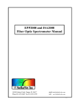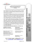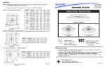
1
User Manual
for
Smithsonian SERC 18 Channel UVB
Scanning Radiometer
Model:
SR-18
Date of Issue:
20 Dec, 2006
Smithsonian Institution
Smithsonian Environmental Research Center
SERC Solar Radiation Laboratory
647 Contee's Wharf Road
P.O. Box 28
Edgewater, MD 21037-0028
(443) 482-2200
FAX: (443) 482-2380
USER MANUAL
for
SMITHSONIAN SERC 18 CHANNEL UVB SCANNING RADIOMETER
Table of Contents
I.
Instrument Description .......................................................................................................... 1
II.
Installation Instructions ......................................................................................................... 2
III.
Operation Instructions .......................................................................................................... 4
IV.
Normal Maintenance Operations ........................................................................................... 6
V.
Data Stream Description ...................................................................................................... 8
Appendix
Light filters in this instrument ...................................................................................... 9
Calibration Constants.............................................................................................. 10
Command Mode Commands .................................................................................. 11
Instrument Case drawing..........................................................................................12
External Power Supply drawing................................................................................13
Cabling diagram ......................................................................................................14
Index …………………………………………..………………………………………………..15
I.
Instrument Description
The radiometer sensor head unit is a weatherproof housing with cosine-corrected diffuser for
light sampling, a filter wheel with 18 2nm-nominal band pass interference filters mounted in the
periphery, a collimator, and a solar blind R-1657 photomultiplier tube (PMT).
All of the components within the sensor head unit are environmentally housed for extended
year-around field operation. All components of the sensor head, except the PMT, are designed to
operate without significant temperature effects over a -25o to +55o C ambient temperature range. The
PMT housing is temperature regulated with a thermostated thermoelectric system. A desiccant canister
filled with indicating silica gel maintains low humidity inside the sensor head. A viewing port in the
canister allows the operator to determine when to replace the silica gel.
The filter wheel turns at 15 RPM and has 2nm half-power-band-width light filters with nominal
center wavelengths from 290nm to 324nm. Every four seconds, a new scan begins. The PMT current
output (which is proportional to the radiation intensity through each filter) is converted to a voltage and
passed to a precision 20-bit A/D converter.
Data from all light filter channels, and the two dark readings are averaged for one minute
intervals, and along with internal temperature and control information, transmitted over three wire RS232 cable to the data acquisition and control unit.
The second unit is the external power supply for the sensor head system. This power supply
provides electrical power both to the head electronics and to the thermoelectric PMT temperature
regulator. This unit is contained in a weatherproof housing.
The third unit, the data acquisition/storage unit, consists of an off-the-shelf PC running in an
office environment with a hard drive, a 3.5 inch floppy disk drive, serial port and a modem/network
connector running under a Windows 9x operating system. Data would routinely be downloaded from
the hard drive to the removable floppy, or transmitted via modem, network or Internet to the data
management facility.
- 1 -
II.
Installation Instructions
A.
Set up radiometer head (SR-18).
The set-up of solar radiation monitoring devices is a subject beyond the scope of
this manual. Most importantly, the operating location should have an
unobstructed a view of the sky as possible from horizon to horizon.
Refer to Instrument Case drawing in the appendix of this manual for dimensions of
the instrument case.
The radiometer should be mounted on a user provided solid mounting stand.
The SERC SR-18 18 channel UV-B radiometer has been mechanically upgraded to
easily level the unit under field conditions.
The instrument now has a 12” x 12” x ¼” thick aluminum leveling baseplate
attached. The baseplate has four leveling screws located, one at each corner. The
plate also has precision locating holes used by SERC in opto-mechanical alignment
and during calibration and re-calibrations of the instrument. This upgrade assures
the repeatability of the position location during subsequent calibrations.
DO NOT remove the baseplate.
DO NOT loosen the mounting hardware holding the radiometer to the leveling
baseplate.
Leveling the SR-18
For operating purposes, the instrument should be leveled to within +/- 10 arc
minutes of true level using a machinist’s level of a minimum of 90 arc seconds
sensitivity or request a G&B “bull’s eye” level from SERC.
The leveling is done against a hard surface backplate – concrete, ¼” thick metal
plate, etc. (A matching aluminum plate, with captive nuts, can be supplied by
SERC if the client is unable to provide a suitable, hard surface, waterproof,
mounting pad.)
The level is placed squarely upon the black “occulting ring” that surrounds the
diffuser. This is the reference surface for alignment, etc. – the highest and flattest
part of the instrument.
The four leveling screws are now used to level the instrument.
- 2 -
II.
Installation Instructions (continued)
When level, two ¼ inch “hold down” screws (along with a flat washer and a lock
washer) are inserted and snugged up to keep the instrument from moving.
The level should be rechecked and the assembly re-adjusted (using the “leveling
screw”) if needed – loosening or tightening the mounting screws as required.
B.
Set up external power supply. This power supply is designed to be mounted with its
cooling fins positioned vertically to increase convection cooling. The power supply
has two nearly universal mounting brackets. These brackets can be used to mount
the supply to any vertical surface or vertical shaft or pipe.
C.
Set up data acquisition system.
D.
Install cabling. Refer to SR-18 Interconnection Diagram, and Instrument Case and
External Power Supply drawings in the Appendix of this document. Note and
follow the color coding of the cable connectors as shown on interconnection
diagram.
1.
Install cables from external power supply to SR-18.
a.
Install W-1002 cable from external power supply to SR-18 main
case.
b.
Install W-1003 cable from external power supply to SR-18
heating/cooling module.
2.
Install W-1004 communications cable from SR-18 to data acquisition
system.
3.
Install W-1001 120 VAC power input cable to external power supply.
At the data acquisition end of the serial data cable is a converter module with a
female DE-9 connector. This connector connects serial RS-232 signals to the data
acquisition system. The protocol of the signal is 9600 bps, 8 data bits, NO parity, 1
stop bit (9600 8 N 1).
E.
Turn-on procedure. When 120 VAC power is applied to the external power supply
and the two cables (W-1002 and W-1003) are connected from the supply to the
SR-18, the radiometer will begin to operate and collect data in its normal scan
mode. In this mode, data will be sent from the SR-18 over the communications
cable (W-1004) every minute. The SR-18 contains a battery-backed clock which
has been set during manufacture so that the operator need now do nothing more to
begin collecting data.
- 3 -
III.
Operating Instructions
After the SR-18 system has been installed, leveled, cabled and powered (See II. Installation
Instructions) the radiometer system is ready to begin collecting data. Within three minutes
after the SR-18 is cabled and powered, it will begin to collect data, and transmit that data
over its communications cable. See Section V. Data Stream Description for information on
the format of the data and on how much data is transmitted from the radiometer. When the
SR-18 is first powered, its internal operating program begins running. This program first
undertakes initialization and checking functions, and then waits for the start of a minute to
begin data collection. Because of these start-up functions and the wait period, a period of
up to three minutes may pass before the SR-18 sends any data down its communication
cable.
See Section IV. Normal Maintenance Operations for daily and weekly checks and
maintenance operations.
Data Acquisition. The SERC SR-18 is designed for flexibility in data acquisition, which
will allow a variety of data acquisition schemes to be used. There are several standard
schemes currently in use.
SERC uses an in-house data acquisition program that captures data and allows the option
of writing that data to a file on the PC. It shows the last acquired reading in a box at the
bottom of the bottom of the window. It also shows the last reading as a reduced spectra and
a daily plot of one filter using the calibrations for that unit. Details of the acquisition
program are in a separate document.
Any serial communications program running on a PC such as Hyperterm, which captures
data and allows the option to write that data to a file on the PC can be used to acquire data
from the SR-18.
For every minute the SR-18 is in standard operating mode it transmits three lines of data.
The first line consists of the instrument ID, and current date and time. The time indicates
the time at the end of the minute which was just recorded – the minute for which the
following data refers.
The second line contains twenty channels of light data. Each channel includes a channel ID
Indicator character (A through T) a sign character (+ or -) and a seven digit (plus decimal)
voltage value. That voltage is the mean of all the scans (normally 14) made during that
minute for that channel. That voltage is proportional to the spectral irradiance in that
channel’s filter pass band, and can be converted to power (milli-watts per square meter per
nanometer) by multiplying the voltage by that channel’s calibration constant (See
Appendix).
The third line consists of diagnostic information.
- 4 -
III.
Operating Instructions (continued)
The SR-18 includes its own battery-backed clock which should be set to local standard
time. There is a provision to set the clock, and to do several other diagnostic and function
setting tasks. This function is called Command Mode, and is accessible to the operator by
sending the SR-18 a Control-A code twice up the communications line which is operating
in full duplex mode. This can be done using Hyper-terminal. Send the Control-A code
twice. After receipt of the double Ctrl-A command the SR-18 will wait until the end of the
current minute, and then enter Command Mode. When the SR-18 enters Command Mode
it will send a list of its current settings down the communications line.
In Command Mode this list of settings will look like this example:
COMMAND
Sleep
DATE:
Enter
MODE
Time: 00:00:00 Wake Time: 00:00:00
DDMMYY TIME: HHMMSS
command:
Sleep Time is the time that the SR-18 will stop taking data each day and Wake Time is the
time that the SR-18 will begin taking data each day. Normally one should not set sleep
time.
The date and time shown are the current SR-18 values.
See the Appendix in this document for SR-18 commands available in Command Mode.
Diagnostics Mode causes the SR-18 to send the value for each channel for each scan down
the communications line, along with the date and time of that scan.
To exit from Command Mode and return to normal data collection, press Ctrl-G.
The SR-18 acquisition program incorporates these commands in the menu bar at the top of
the screen. Re-setting time and date can be done without stopping and starting the
acquisition program.
During normal data collection the SR-18 may also send a diagnostic message:
WATCHDOG ALERT.
This message means that there was an operating problem in the current minute of data
collection. After the SR-18 sends this message, it will attempt to begin data collection and
transmission in a normal manner again. If several WATCHDOG ALERT messages occur
in a row (they can occur as frequently as every two seconds or up to three minutes apart),
the operator should turn off the 120VAC power to the SR-18, leave the power off for at
least 30 seconds, and then turn on the power again. If WATCHDOG ALERT messages
again occur, the SR-18 will require non-field maintenance.
- 5 -
IV.
Normal Maintenance Operations
A.
B.
Observe for normal operation
1.
Instrument should be checked daily for normal operation. Items to check:
a.
Is data being collected normally in standard data format (see Section
V. Data Stream Description)?
b.
Are date and time correct in the data stream?
c.
Are there 14 data sets per minute?
d.
Is the STATUS: indicator 0?
e.
Is the TEMP: between 0 and 60?
2.
If any abnormalities are noted in the operation of the radiometer, contact the
service depot. There are no field serviceable components inside the
radiometer. The instrument must be returned to the service center for depot
level maintenance.
Clean diffuser
1.
Diffuser (light entrance port) should be cleaned with clear water, and wiped
dry with a soft cloth at least once a week. Daily CLEANING is required
under high pollen or dust conditions. In below freezing weather, alcohol
should be used in place of water.
C.
Check desiccant for dark blue color. If desiccant is depleted, as indicated by a pale
blue, pink or white color it should be changed.
D.
Procedure to change desiccant.
1.
There are no field serviceable components inside the radiometer. Therefore
the case should never be opened in the field.
2.
Unscrew desiccant holder and remove from end plate.
3.
Locate 0.050” socket head set screw(s) in threaded area of desiccant holder.
Some desiccant holders have two set screws.
4.
Hold canister with wire basket down and the viewing window up to prevent
spilling of desiccant.
5.
Loosen the set screw(s) that you located in step 3.
6.
Gently twist basket from main (window) section of holder.
- 6 -
IV.
Normal Maintenance Operations (continued)
7.
Discard old desiccant, or reserve for renewal. Desiccant can be renewed by
heating in an oven until the dark blue color reappears.
8.
Blow off any desiccant dust from both sections of the holder away from the
instrument with dry air.
9.
Fill the desiccant basket to the brim with fresh indicating desiccant.
10.
Twist together the two sections of the holder until they mate against the stop,
tighten the set screw(s).
11.
Reassemble the desiccant holder to the case end plate and screw into place
hand tight.
- 7 -
V.
Data Stream Description
Data from SERC 18 Channel Radiometer
Each minute of data from the radiometer (using version 48 PROM software) is 280 bytes.
This is an example of that one minute’s data format (where <CR/LF> refers to a carriage
return and line feed character pair):
UK DATE: 170896 TIME: 121701<CR/LF>
A+00.12576B+00.14404C+00.11544D+00.10206E+00.09530F+00.07946
G+00.05314H+00.06424I+00.03908J+00.00046K+00.04562L+00.03476
M+00.01582N+00.01356O+00.01418P+00.01446Q+00.01594R+00.01806
S+00.01696T+00.00042<CR/LF>
DATA SETS: 014 STATUS: 0 TEMP: +39.57 FSC: 000<CR/LF>
Including CR/LF characters: Total: 280 bytes per minute
-ID line is 30 bytes = 16,800 bytes per hour
-data line is 202 bytes = 302,400 bytes for an 18 hour day
-Status line is 48 bytes
SR-18 CHANNEL DESIGNATIONS
Channel ID
A
B
C
D
E
F
G
H
I
J
K
L
M
N
O
P
Q
R
S
T
Nominal Filter Center Wavelength
290nm
292nm
294nm
296nm
298nm
300nm
302nm
304nm
306nm
Dark Zero #1
308nm
310nm
312nm
314nm
316nm
318nm
320nm
322nm
324nm
Dark Zero #2
- 8 -
Appendix – Light Filters
Sample
Light Filters Installed in SERC 18 Channel UVB Radiometer UK
(Filter run: 30JUL96)
Channel
A
B
C
D
E
F
G
H
I
J
K
L
M
N
O
P
Q
R
S
T
Nominal
CWL
(nm)
290
292
294
296
298
300
302
304
306
308
310
312
314
316
318
320
322
324
Filter name
(* = 0.5ND filter)
290/2NM 2593 BARR #5
292/2NM 2593 BARR #4
294/2NM 2593 BARR #9
296/2NM 2593 BARR #9
298/2NM 2593 BARR #9
300/2NM 2593 BARR #11
302/2NM 2593 BARR #10
304/2NM 2593 BARR #9
306/2NM 2693 BARR #9
Dark Zero Channel #1
308/2NM 2593 BARR #12
310/2NM 2593 BARR #10
312/2NM 2493 BARR #11
314/2NM 2493 BARR #9
316/2NM 2593 BARR #10
318/2NM 2593 BARR #10
320/2NM 2493 BARR #10
322/2NM 2593 BARR #10
324/2NM 2493 BARR #10
Dark Zero Channel #2
* 0.5 N.D. neutral density filters in these channels.
- 9 -
Measured
CWL
(nm)
BW
(nm)
Peak
(T)
290.36
291.91
293.90
296.16
297.79
299.99
301.39
303.89
305.94
2.13
2.04
2.30
2.20
2.15
2.06
2.17
2.52
2.12
0.16
0.16
0.14
0.11
0.12
0.13
0.14 (*)
0.18
0.18
307.76
310.19
312.58
314.29
315.85
318.04
320.80
321.95
323.72
2.34
2.60
2.05
2.43
2.20
2.37
2.71
2.31
2.28
0.15
0.10
0.14
0.13
0.15
0.18
0.14
0.18
0.18
Appendix – Calibration Constants
Calibration of SERC 18 Channel Scanning Radiometer
Calibration of UK
xx Jul, 1996
* 0.5 N.D.
Channel
ID
Nominal
Filter
CWL
(nm)
Measured
CWL
(nm)
EN-74
lamp energy
at CWL
(µW/sq.cm/nm)
Mean
Raw
Values
(Volts)
Calibration
Constants
(mW/sq.M/nm/volt)
A
B
C
D
E
F
G
H
I
290nm
292nm
294nm
296nm
298nm
300nm
302nm
304nm
306nm
290.36
291.91
293.90
296.16
297.79
299.99
301.39
303.89
305.94
0.1333
0.1437
0.1549
0.1671
0.1804
0.1928
0.2050
0.2224
0.2388
0.20540
0.26032
0.30028
0.18634
0.20295
0.17191
(*) 0.06174
0.07094
0.04358
6.48987
5.52007
5.15854
8.96753
8.88893
11.21550
33.20214
31.35000
52.62578
J
Dark 1
K
L
M
N
O
P
Q
R
S
308nm
310nm
312nm
314nm
316nm
318nm
320nm
322nm
324nm
307.76
310.19
312.58
314.29
315.85
318.04
320.80
321.95
323.72
0.2507
0.2698
0.2946
0.3124
0.3273
0.3508
0.3807
0.4005
0.4121
0.04197
0.03807
0.02197
0.01766
0.01658
0.01734
0.01366
0.01224
0.01126
59.73741
70.87876
134.11026
176.94704
197.46606
202.36516
278.71733
327.33960
365.88831
T
Dark 2
- 10 -
Appendix - Command Mode Commands
SERC 18 Channel Radiometer Commands
Enter Command Mode:
Set time and date:
Read Temperature:
Enter Diagnostics Mode:
Return to Command Mode from Diagnostics Mode
Exit from Command Mode to Normal Operation Mode:
Ctrl-A (twice)
Ctrl-B
Ctrl-E
Ctrl-F
Ctrl-A (twice)
Ctrl-G
Perform a single conversion:
*Set the hour for Sleep Mode (0-23):
*Set the hour for waking (0-23):
Ctrl-H
Ctrl-I
Ctrl-J
* Do Not Use!!
- 11 -
Appendix - Instrument Case drawing
- 12 -
Appendix - External Power Supply drawing
- 13 -
Appendix – Cabling diagram
- 14 -
Index
-Ccables
cabling diagram................................................................................................................... 14
installation ………………………………………………………………………………. 3
calibration constants....................................................................................................................... 10
channel
identifiers ............................................................................................................................. 8
clock
set on/off time ...................................................................................................................... 5
set sleep/wake time .............................................................................................................. 5
Command Mode
description........................................................................................................................... 5
commands list ..................................................................................................................... 11
-Ddata
description........................................................................................................................ 1, 8
format.................................................................................................................................. 8
acquisition............................................................................................................................ 4
desiccant.......................................................................................................................................... 6
-Ffilters
description........................................................................................................................... 1
in this instrument................................................................................................................... 9
-IInstallation instructions..................................................................................................................... 2
instrument
description........................................................................................................................... 1
-MMaintenance operations.................................................................................................................... 6
-OOperating instructions....................................................................................................................... 4
-WWATCHDOG ALERT ..................................................................................................................... 5
- 15 -