1
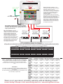
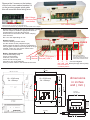
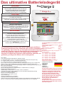
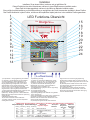
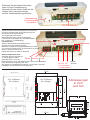
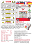
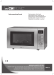
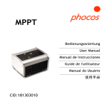
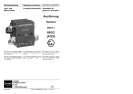
The ultimate battery charger
DANGER
HIGH VOLTAGE
AVOID SERIOUS INJURY OR DEATH FROM ELECTRICAL
SHOCK.
BEFORE PERFORMING ANY ELECTRICAL WORK TURN
OFF AC POWER SUPPLY
Pro Charge
Pro
U
Charge ULTRA
DANGER
EXPLOSION HAZARD
Sterling Power
AVOID SERIOUS INJURY OR DEATH
MAKE CONNECTIONS IN AN ATMOSPHERE FREE OF
EXPLOSIVE FUMES
GLOBAL A/C Input & Active Power Factor Correction
AVOID SERIOUS INJURY FROM ELECTRICAL BURNS AND
SPARKS.
BEFORE PERFORMING ANY ELECTRICAL WORK
DISCONNECT ANY DC POWER SUPPLY FROM UNIT
Auto Temp Control
HOT SURFACES – TO REDUCE RISK OF BURNS DO NOT TOUCH
WHILE IN SERVICE
Amps
Volts
RoHS
compliant
Active PFC
0%
Multi Speed Cooling
1 2 3
CHARGER MODE
System self test
OK
SETUP
ENTER
100%
Charger Output
AUTO CONSERVATION MODES
Fault
CAUTION
www.sterling-power-usa.com
AC Power
Stand-by
Battery Health Program
Fast Charge
Absorption
De-sulphation
Battery Type
Preset 2
LOW VOLTAGE
Progressive DIGITAL software control
www.sterling-power.com
Preset 1
WARNING
Open lead acid
Sealed lead acid
Float
CHARGE INFORMATION
DC Output Service
DC Low Voltage
A.G.M
DC High Voltage Trip
GEL
High Charger temp trip
Lithium (LiFePO4)*
Check Fan
Calcium / Custom
To avoid serious injury or death from electric shock. Before
opening, turn off the main A/C power. Do not expose to rain
nor spray. Replace defective wires/cords before use. Always
read the manual before operating the charger.
*Lithium must be used in conjunction
with a lithium balancing system.
High current capable of causing sparks burns and fires,
always disconnect the D/C cables from the batteries
before working on the D/C side. Intended for both
COMMERCIAL and DOMESTIC use.
High Voltage A/C WARNING Low Voltage D/C
CHARGE ONLY USER SELECTED TYPE BATTERIES
(Flooded, AGM, GEL, lithium or Calcium)
OTHER TYPES OF BATTERIES MAY BURST CAUSING PERSONAL
INJURY AND DAMAGE
RISK OF ELECTRIC SHOCK, NO USER SERVICEABLE PARTS,
RETURN TO MANUFACTURER FOR SERVICING
THIS UNIT IS IGNITION PROTECTED
This product requires a knowledge of both a/c and d/c electrical
installation. Please do not install or attempt to install this product
unless you are qualified to do so. All effort is made to make the
instructions as safe as possible but it is not possible to cover all
electrical safety and installation aspects. Sterling can only
assume a certain basic knowledge is held by the installer.
Top Function
1) 11 pre programmed battery curves including LiFePO4.
2) 1 custom set, can be set from charger, no need for computer.
3) 2 x digital meters for current and voltage measurement.
4) 1 x power meter to show what reserve power left on the unit.
5) PFC, active, up to 0.99 pf, ensuring efficient power conversion, up to almost 90% as
opposed to about 50% for older non PFC technology.
6)New synchronised rectification output as opposed to diode output, giving up to an extra10%
efficiency
7) High voltage de-sulphation cycle.
8) New, low activity, standby mode to increase battery life.
9) Battery health program.
10) Multiple speed fan control to reduce unnecessary fan noise experienced by the customer,
even though the new extreme efficiency reduces the need for fans, at high ambient
temperatures: ( 40-50 deg C ) fans would still be required to ensure operation.
11) Primary ( processor digitally controlled ) and an emergency backup secondary (analogue
controlled) high voltage trip.
12) 32 LED information pane.
13) Internal scan and systems check.
14) Remote control
15) Small footprint and light weight
16) Include battery temperature sensor
17) As with all our marine chargers no exposed ferrous metals used, only aluminium/stainless
steel/copper /brass/gold, exposed to air.
18) % power reduction to allow unit to work with restricted power available ( available on local
control or remote control panel ),
19) Conforms to A.B.Y.C. drip test, is water proof from water directly dropped on to the top of
the unit ( +/ - 17 deg ) if installed correctly (vertically)
20) The printed circuit boards are conformal coated for high humidity operations.
12V 60A model, all other units pro rata
Input voltage range
90-270V 40-70Hz
Power Factor at 230V
0.95
Efficiency
88.5%
Full load current ( 110/230v )
10 /4.8
Ripple noise ( R.M.S. )
50mV
Ground leakage
0.75 mA
Generator/ mains power required to run unit (
watts )
12 v 20 amp approx 300 watts
12 v 30 amp approx 450 watts
12 v 40 amp approx 600 watts
12 v 50 amp approx 750 watts
12 v 60 amp approx 900 watts
24 v 20 amp approx 600 watts
24 v 30 amp approx 900 watts
volt metre accuracy
+/- 1.5%
amp metre accuracy
+/- 1%
Tested to CE standards
EN61000-3-2 EN61000-3-3
EN55014-1 EN 55014-2
EN60335-2-29
This appliance is not intended for use
by persons (including children) with
reduced physical, sensory or mental
capabilities, or lack of experience and
knowledge, unless they have been
given supervision of instruction
concerning use of the appliance by a
person responsible for their safety.
Children should be supervised to
ensure that they do not play with the
appliance.
Installation
Install in cool dry well ventilated space.
This product has a high heat tolerance and can be installed in a engine room.
This product is ignition protected and can be installed near the batteries.
Charger MUST be installed vertically to allow for convection air flow and also in the vertical position
the product is drip proof.
The product will work in any position but we cannot guarantee the drip proof aspect in any other position
1
2
3
4
5
6
7
8
9
10
11
12
13
14
Quick LED feature guide
Pro
15
16
17
18
19
20
21
22
23
24
Charge ULTRA
Warm air
out
Sterling Power
GLOBAL A/C Input & Active Power Factor Correction
Progressive DIGITAL software control
www.sterling-power.com
www.sterling-power-usa.com
AC Power
Auto Temp Control
RoHS
compliant
Amps
Volts
Active PFC
0%
1 2 3
Charger Output
SETUP
ENTER
De-sulphation
Battery Type
Preset 1
OK
Fault
Absorption
Fast Charge
CHARGER MODE
System self test
Battery Health Program
Stand-by
AUTO CONSERVATION MODES
Preset 2
Multi Speed Cooling
100%
Float
CHARGE INFORMATION
Open lead acid
DC Output Service
DC Low Voltage
Sealed lead acid
A.G.M
DC High Voltage Trip
GEL
High Charger temp trip
Check Fan
Lithium (LiFePO4)*
Calcium / Custom
To avoid serious injury or death from electric shock. Before
opening, turn off the main A/C power. Do not expose to rain nor
spray. Replace defective wires/cords before use. Always read the
manual before operating the charger.
*Lithium must be used in conjunction
with a lithium balancing system.
High current capable of causing sparks burns and fires,
always disconnect the D/C cables from the batteries before
working on the D/C side. Intended for both COMMERCIAL
and DOMESTIC use.
High Voltage A/C WARNING Low Voltage D/C
Lithium battery Use
this charger must not be used to
charge lithium battery cells by itself,
you cannot charge lithium cells on
there own you must have a lithium
balancing device in conjunction with
the charger.
Cooling
Air flow
1) Ammeter, shows the total current being produced
by the charger
2) Voltmeter, showing the average voltage being
produced by the charger
3) Power meter, shows the % power being produced
by the unit and the remaining power available
4) A/C power, shows the a/c power is connected and
the product is live, flashes if power is available but
the unit is switched off ( see on/off later ) push
buttons. Setup and up arrow for 5 secs to activate.
5) Auto temp control, shows the battery temp sensor
is connected and operational. If sensor not
connected then the unit will default to a 20 deg C
charge curve.
6) Shows that the active PFC (power Factor
Correction is active)
7) Fan speed control, varies depending on temp, 3
speeds.
8) Standby, charger power system power
requirement very low, unit on low float voltage to
prolong battery life.
9) Fast charge unit on constant current mode
10) OK, unit operating within normal parameters
11) Fault, fatal fault, needs returned for repair
12) Battery type selector, shows which battery
charger curve in operation (adjustable )
13) Buttons to select charge options (see later in
instructions) also used to switch unit off or on in
conjunction with the setup button ( see 14 )
Off select button plus down button for 5 sec
On select button plus up button for 5 sec
14) Button to enter selections, also use to switch unit
on/off in conjunction with the up or down button
15) Battery health program, unit doing a 21 day de-
sulphation cycle.
16) Absorption, charger on initial charge cycle.
17) De-sulphation cycle operational
18) Float, unit on float charge or power pack mode,
main charge complete.
19) DC output service, output working correctly
20) DC output low voltage warning, either batteries
are very low / more power is being taken than the
charger can supply / or the charger is defective.
21) High voltage trip, the unit is defective and tripped
itself, or a high back D/C voltage has been detected,
like a wind generator reg gone defective.
22) High charger temp, if the unit is positioned in too
hot an environment and over heated, or the fans
have failed.
23) Check fans, fans are thought to be defective.
24) Case screws to access the wiring of the product.
Battery type Preset information (for 24 v x all voltages by 2)
Preset 1
Preset 2
Battery type
Absorption
Minimum
Charge
Float
14.8
14.4
14.35
14.0
14.8
15.1
15.5
13.6
13.6
13.35
13.7
14.4
13.6
15.5
Charge
Float
14.7
13.4
14.6
13.4
14.6
13.7
14.4
13.8
14.6
14.4
Custom set
15.5
15.5
Rough guide
only
Flooded/open lead acid
Sealed lead acid
AGM
Gel
Lithium LiFePO4
Calcium / Custom
De-sulphation / Equalization
time factor
8
10
9
10
8
8
NA
absorption
time (mins)
60
360
60
600
240
60
240
Maximum
absorption
time (mins)
600
720
480
1200
480
360
240
Pro
Charge ULTRA
Sterling Power
Ground / bonding / earthing . This is
extremely important and often overlooked
there are, in effect, 3 grounds,
1)the earth wire ( A/C input, the ground ) ,
2) the Chassis / bonding ground ( going to
a vehicle body / boats bonding system,
the bolt on the side of the charger )
3)the D/C negative.
In most installations all these will end up
at the same point, ie the A/C power source
should be connect to the boat/vehicle
chassis ( for safety ).The chassis earth will
also go there, and the D/C neg should
also go there, in effect bonding the total
system together ensuring any fault to the
chassis will blow a fuse. This could vary
for steel/aluminium boats.
Ground / Chassis
Boat grounding
GLOBAL A/C Input & Active Power Factor Correction
Progressive DIGITAL software control
www.sterling-power.com
Earth /chassis
boats bonding
www.sterling-power-usa.com
AC Power
Auto Temp Control
Active PFC
0%
Multi Speed Cooling
1 2 3
Preset 2
Fault
Absorption
SETUP
ENTER
Float
De-sulphation
Battery Type
Preset 1
OK
Battery Health Program
Stand-by
Fast Charge
CHARGER MODE
System self test
100%
Charger Output
AUTO CONSERVATION MODES
AC circuit breaker
RoHS
compliant
Amps
Volts
Open lead acid
CHARGE INFORMATION
DC Output Service
DC Low Voltage
Sealed lead acid
A.G.M
DC High Voltage Trip
GEL
High Charger temp trip
Lithium (LiFePO4)*
Check Fan
*Lithium must be used in conjunction
with a lithium balancing system.
Calcium / Custom
To avoid serious injury or death from electric shock.
Before opening, turn off the main A/C power. Do not
expose to rain nor spray. Replace defective wires/cords
before use. Always read the manual before operating the
charger.
High current capable of causing sparks burns and
fires, always disconnect the D/C cables from the
batteries before working on the D/C side. Intended
for both COMMERCIAL and DOMESTIC use.
High Voltage A/C WARNING Low Voltage D/C
Any outputs not being used should be linked
across to one that is, this is not a requirement
for these new models but is good practice as it
helps spread loads etc.
D/C - Fuse selection, as per the
diagram each positive output from the
charger to the battery must be fused.
Choose a fuse that is about 20%
higher amperage rating than the
maximum rating of the charger, and
round it up, remember this fuse is
primarily protecting the cables and not
the product. E.g. a 20 amp charger
would have about a 25 amp fuse, a 60
amp charger about a 75 amp fuse. A
full range of fuses and fuse holders
are available from Sterling.
D/C fuse
D/C fuse
D/C fuse
20% larger
amperage than
charger output
20% larger
amperage than
charger output
20% larger
amperage than
charger output
_
+
12 or 24 v battery bank
_
+
12 or 24 v battery bank
_
+
12 or 24 v battery bank
A/C installation (input to charger)
Wiring, using ring or captive spade connections and a proper crimping tool attach the A/C cables Live ( line ) Neutral and Earth / Ground. Repeat
the procedure for the breaker side of the install, support the cable every 18 inches/ 0.5 metre and protect from sharp edges when passing through
bulkheads and all other openings as per any standards which apply to the installation.
AC input rating
AWG
AC BREAKING SIZE
Charger Model
PCU1210 – 2 Output
PCU1215 – 3 Outputs
PCU1220 – 3 Outputs
PCU1230 – 3 Outputs
PCU1240 – 3 Outputs
PCU1250 – 3 Outputs
PCU1260 – 3 Outputs
PCU2420 – 3 Output
PCU2430 – 3 Outputs
110 Volt
Breaker
6 Amp
7 Amp
8 Amp
11 Amp
14 Amp
16 Amp
16 Amp
14 Amp
14 Amp
220 Volt
Breaker
4 Amp
5 Amp
6 Amp
7 Amp
8 Amp
10 Amp
10 Amp
8 Amp
8 Amp
D/C installation (output from charger)
Choosing cable- unlike A/C conductors, D/C are very sensitive to
voltage drop. The longer the cable runs the larger the cable
thickness needs to be, ensure only quality fire retardant cable is
used.
IMPORTANT
The closer to the batteries you fit the charger the better. Not only
do you save expensive cable you also get better performance from
the charger.
The cable should be properly rated 105 deg C fire resistant. do not
use solid cable or speaker wire
25ft
(7.6m)
18
18
18
16
16
14
14
16
16
10 amp
Distance
AWG
15 amp
Distance
AWG
20 amp
Distance
AWG
30 amp
Distance
AWG
40 amp
Distance
AWG
50 amp
Distance
AWG
60 amp
Distance
AWG
Cable length
50ft
100ft
(15.2m)
(30.5m)
16
14
16
14
14
12
14
10
12
10
12
8
12
8
14
10
14
10
150ft
(45.6m)
12
12
10
8
8
8
8
8
8
Length of conductor ( cable ) to and from power source
3m (10 ft)
5m (15ft)
7m (22ft) 8m (25ft)
9m (30ft)
14
12
10
10
10
3m (10 ft)
12
5m (15ft)
10
7m (22ft)
10
8m (25ft)
8
9m (30ft)
8
3m (10 ft)
10
5m (15ft)
10
7m (22ft)
8
8m (25ft)
6
9m (30ft)
6
3m (10 ft)
10
5m (15ft)
8
7m (22ft)
6
8m (25ft)
6
9m (30ft)
4
3m (10 ft)
8
5m (15ft)
6
7m (22ft)
6
8m (25ft)
4
9m (30ft)
4
3m (10 ft)
6
5m (15ft)
6
7m (22ft)
6
8m (25ft)
4
9m (30ft)
2
3m (10 ft)
6
5m (15ft)
4
7m (22ft)
4
8m (25ft)
2
9m (30ft)
2
There is a 2 year return to factory warranty with all Sterling product
Contact Sterling in Europe or USA. www.sterling-power.com www.sterling-power-usa.com
Remove the 2 screws on the bottom
of the front cover marked number 24
on the previous pages quick guide
this will reveal the main wiring area.
High Voltage
A/C cover plate
and clamp
PCU 12V 10A & 20A models have ring
terminal screw connectors as depicted above.
N.B. the 10A model has only 2 outputs, all other models have 3 outputs.
D/C cable clamp
Remove the 2 screws on the A/C area and the 3 screws on
the D/C clamps to enable the appropriate wires to
be attached A/C input 90-160 volts A/C.
Ensure secure connections and correct crimping
tools are used
D/C 12 or 24V depending on unit.
Battery temperature sensor connection
Remote control
Remote control
Insert the Sterling remote control
into the remote socket ( telephone type )
Please note that when the remote is inserted the
front program controls on the local panel no longer
operate, control is in the remote. Remove the
remote to use local controls.
Battery Temperature sensor
Connect the battery temp
sensor to the position
Live Neutral
as shown, connect the
Live Neutral
sensor end to the neg stud
terminal on one of the batteries
which you think will be in the hottest environment.
A
FUSES
D/C
PCU 12V / 30-60A &
24V 20-30A have bolt
terminals as depicted above
rather than screw terminals.
Earth ( European )
Ground ( USA )
1
2
3 Common Negative
red red red Black (Europe) Yellow (USA)
Pos terminals on
3 x battery banks
1
5 [130]
8
260 mm
10 1/4 inch
24 vNautic
30 ampiQ
Pro
12-60
5
3 [93]
8
90 mm
3 ½ inch
81
2 [215]
Cut out
90 x 62 mm
44 mm
1 3/4 inch
215 mm
8 ½ inch
dimensions
in inches
and ( mm )
3
12 [315]
8
85 mm
3 3/8 inch
ProMariner
12 v 50-60 amp
85 mm
3 and 3/8 inch
90 mm
3 ½ inch
12 v 10-40 amp
24 v 20 amp
5
38 [93]
3
7 4 [198]
198 mm 7 3/4 inch
INSTALLATION OF THE BATTERY CHARGER
sulphation light will flash, continue to the next setting, the 2 x
voltmeters will display “FAC” “DEF” for factory default.
Position the charger in a cool, dry and well ventilated space, ensuring a reasonable airflow
4. Press the “Setup/Enter” button to confirm selection, the charger will rearound the charger. Do not install in a cupboard or sealed compartment.
boot.
Charger MUST be installed vertically.
POWER LEVEL ADJUSTMENT
Install as close to the batteries as possible, preferably within 2 meters of the batteries.
1. Hold the“↑” and “↓” buttons simultaneously for about 20 sec
2. Volts will display “PL” for Power Level, and the amps 100 for 100%
To obtain maximum waterproof/ingressproof rating (IP42) mount the charger vertically.
However, the unit will work just as well in any fastening orientation so long as it is dry.
3. Press the “↓” to adjust the amperage display from 100, 75, 50, 25%
With regards charging cooling, the unit has thermostatically controlled force draft cooling and
output.
is thus able to remain cool whether fastened in any orientation.
4. Press the “Setup/Enter” button to confirm selection.
NOTE: If no action is taken after 15 seconds, the unit reverts to 100%
Always isolate the A/C power before working on it
power.
- Before switching on the charger it is important to set up the battery type. Please choose a
OPTIONAL REMOTE
battery type from the table (at the bottom of page 2). There are so many different profiles, and When the optional remote is installed, it will display the current status of the
battery companies change them all the time. It is impossible to keep up, so in order to assist
charger along with the voltage and amperage.
our customers we offer the option of preset battery types: Flooded, sealed, AGM, Gel,
1. The Blue LED is illuminated when the power is ON
LiFePO4, calcium and custom. Each type has 2 preset algorithms, for instance: Gel preset 1 is
2. BACK LIGHT can be set to ON or OFF by toggling the on/off button,
the USA Gel spec (absorption 14.0V and float 13.7V) and Gel preset 2 is the Europe Gel spec
with short sharp action. The default is ON.
(absorption 14.4V and float 13.7V). We also provide the charge voltages related to this cycle.
3 To switch the product off hold the button for about 3 seconds and
In most cases these are correct; however, if in doubt install on the lower voltage setting until
release, the unit will shut down, to switch back on again simply push
you have checked with your battery supplier.
the button and the unit will restart.
In the event of different types of batteries, the lowest battery voltage type must be selected.
4
ALARM can be silenced or made audible by toggling the ALARM
button, default is audible
Never charge a battery on a higher setting than it should. If a bespoke battery is being used
then use the CUSTOM setting, this gives the user the ability to set their own absorption/float
PROGRAMMING USING THE OPTIONAL REMOTE.
voltages.
Connect the cables as in the diagram. Ensure that all the terminals are used. In the event of
only one battery being charged, connect the surplus positive output to another used output.
This ensures correct regulation. Failure to do this will reduce the charging performance.
IMPORTANT: Always connect the cables to the charger first then run them to the batteries.
Never connect to the batteries first and then run to the charger.
Operating Instructions
From main charge only (not remote control)
On/off the unit can be switched off using the controls on the charger main control
panel ( it can also be switched on/off on the remote ( see later )
Unit On press setup and the up button, hold for 10 sec.
Setup
Enter
Remote control operation. When installing the remote control from new,
if the charger is already on and you add the remote control the remote will not
work, you must add the remote control then switch the charger off for 1 min then
switch on again to reset the software, the charger will then pick up the remote’s
presence and the remote will work.
Pressing SETUP/ENTER displays “SCROLLING”
Setup
Unit Off press setup / enter and down for 10 sec. Enter
The blue A/C power LED will flash to show the power is available but the unit is
not activated
1.
using the
items.
FACTORY RESET
To return the unit to original factory settings (Flooded Lead Acid)
1. Enter battery type selection as above
2. Use the “↓” key until you leave the battery type LED panel then the de-
directional keys scroll through the below menu
Setup
2.
SELECTING BATTERY TYPE
To select a battery type/charging profile perform the following:
1. Press and hold the “Setup/Enter” button for over 10 seconds, then
release the button
2. The current battery type and Voltage/Amperage displays will flash. The
voltage and ammeter will now display voltage, the left hand screen
(marked voltmeter) will show the high charge voltage setting and the
right hand screen (marked ammeter) will show the low charge / float /
power pack voltage setting.
3. Use the “↑” and “↓” keys to scroll through all the different battery types.
The LED display on the charger in the battery type section will move
through the different types.
4. The Volts and Amps readout will display the charge/conditioning and
float voltages for each profile highlighted.
5. Press the “Setup/Enter” button to confirm selection, the LED will remain
solid or leave for 30 seconds and the selection will be locked in
automatically .
ADJUSTING THE CUSTOM BATTERY TYPE SELECTION
NOTE: *Damage can result to your batteries from improper use of the custom
setting. Any damage experienced while using this setting is the responsibility
of the user and not covered by any Sterling warranty. ALWAYS consult the
battery manufacturer if you are unsure of the battery chemistry and charge
profile required.
1. Follow above steps and select the “Custom” option on the battery
type display and press enter to enter it.
2. The “Fast charge & Adsorption” LEDs will be blinking, indicating you are
in the adjustment mode
4. The left hand meter will blink and the right hand meter will go out. The
numbers on the left hand meter will be the high voltage setting, adjust
as required by using the “↑” and “↓” to select voltage up to 15.1V,
press enter when you have selected the correct voltage, then the right
hand screen will flash, this is the float voltage settings again using the
arrows to set this voltage then press enter to finish.
NOTE: During this process, real-time voltage and amperages will not be
displayed.
SELF TEST MODE
1. Press and hold the “Setup/Enter” and the “↑” and “↓” buttons
simultaneously for 10 seconds then release
2. The “Self Test” LED will flash until the test is complete
3. OK or Fault LED's will be displayed, see the Troubleshooting section if
the Fault LED is illuminated.
and
Pressing SETUP/ENTER Enter . Enter scroll mode and it will display
automatically each option every 10 seconds, or you can use the arrow
buttons to speed up the scroll time if you need to get to information
faster.
3. Using the directional keys again will display additional options to be
selected, press SETUP/ENTER when done.
1) Charger name = displays charger model.
2) Charger status = displays charging /absorbation/float status.
3) Battery type selection, scroll through the battery types.
4) Time to absorption= displays the time left in absorption mode.
5) Run Time = displays units total running time.
6) Power Level= displays current output power levels, allows for power
reduction in this screen, push enter again to power reduce.
7) Charger temperature
8) Battery temperature = displays battery temperature
10) Transformer temperature = displays the transformer temperature
11) Faults = displays any faults active or simply ”No faults displayed”
12) Company information
13) Total run time
14) Software version = the installed software version
IMPORTANT SAFETY INSTRUCTIONS
SAVE THESE INSTRUCTIONS - this manual contains important safety
instructions for the Pro Charge Ultra
1) Do not expose this unit to rain or snow
2) Use of attachments not recommended or sold by Sterling Power, LLC will void
warranty and may result in the risk of fire.
Remote control short cuts
By pressing the below sequence on the remote control you can quickly
access the most used functions
press and hold for 10 seconds to force into “Float Mode”.
press and hold for 15 seconds for direct access to power
reduction mode.
Setup
Enter
press these 3 and hold for 5 seconds to start a self test
Alarm
Setup
Enter
press and hold for 3 seconds- restores factory
defaults.
SHOCK OR PERSONAL INJURY.
3) Do not operate the unit if it has been dropped or visibly damaged in any way
4) Do not disassemble the unit. If service or repair is required please contact
Sterling at www.sterling-power.com or www.sterling-power-usa.com
5) To reduce the risk of electrical shock, remove connection to AC shore / station
power and DC connections prior to maintenance or cleaning.
6) Turning off controls WILL NOT reduce this risk.
7) Use of extension cord should not be used unless absolutely necessary. If an
extension cord must be used, make sure:
a) That pins on plug of extension cord are the same number, size and shape
of those of the plug on the charger.
b) That extension cord is properly wired and in good electrical condition.
c) That wire size is large enough for AC ampere rating of charger as
specified in table (page3)
6) Do not operate charger with damaged cord or plug - replace the cord or plug
immediately.
7) Do not operate charger if it has received a sharp blow, been dropped, or
otherwise damaged in any way; take it to a qualified serviceman.
8) Do not disassemble charger; take it to a qualified serviceman when service
or repair is required.
9)To reduce risk of electric shock, unplug charger from outlet before attempting
any maintenance or cleaning. Turning off controls will not reduce this risk.
WARNING – RISK OF EXPLOSIVE GASES
WORKING IN THE VICINITY OF A LEAD-ACID BATTERY IS DANGEROUS.
BATTERIES GENERATE EXPLOSIVE HYDROGEN GAS DURING NORMAL
BATTERY OPERATION. FOR THIS REASON IT IS OF UTMOST
IMPORTANCE THAT EACH TIME BEFORE USING YOUR CHARGER YOU
READ THIS MANUAL AND FOLLOW THE INSTRUCTIONS EXACTLY.
! To reduce the risk of a battery explosion, follow these instructions and those
published by the battery manufacturer and any equipment you intend to use in
the vicinity of the battery(s). Carefully review the cautionary markings on this
equipment.
! SPARK – Be very cautious about dropping metal objects such as screwdrivers
and wrenches onto a battery. This could short-circuit the battery and
immediately cause a spark that may result in a fire or explosion.
! REMOVE – All personal metal items such as rings, watches, bracelets, etc.
when working near a battery. A battery can produce a short circuit current high
enough to weld a ring or any other metal causing serious burns.
! DRY CELL BATTERIES – Never use the battery charger feature to charge dry
cell batteries that are commonly used with home appliances i.e. a cordless
power drill battery. These batteries may burst and cause injury to persons and
damage property.
! FROZEN BATTERY – Never charge a frozen battery.
b) Never place charge directly above battery being charged from battery will
corrode and damage charger.
c) Never allow battery acid to drip on charger when reading electrolyte
specific gravity or filling battery.
d) Do not operate charger in a closed-in area or restrict ventilation in any
way.
e) Do not set a battery on top of charger.
14. DC CONNECTION PRECAUTION
a) Connect and disconnect DC output clips only after setting any charger
switches to “OFF” position and removing AC cord from electric outlet. Never
allow clips to touch each other.
15. FOLLOW THESE STEPS WHEN BATTERY IS INSTALLED IN
VEHICLE/BOAT. A SPARK NEAR BATTERY MAY CAUSE BATTERY
EXPLOSION. TO REDUCE RISK OF A SPARE NEAR BATTERY.
a) Position AC and DC cords to reduce risk of damage
b) Stay clear of fan blades, belts, pulleys, and other parts that can cause
injury to persons.
c) Check polarity of battery posts. POSITIVE (POS,P,+) battery post usually
has larger diameter than NEGATIVE (NEG,N,+) post.
d) Determine which post of the battery is grounded
e) For negative-grounded, connect POSITIVE (RED) clip from battery
charger to POSITIVE (POS,P,+) ungrounded post of battery. Connect
NEGATIVE (BLACK) clip to vehicle chassis or engine block away from
battery. Do not connect clip to carburetor, fuel lines or sheet-metal. Connect
to a heavy gauge/gage metal part of the frame or engine block.
g) When disconnecting charger, turn switches to off, disconnect AC cord,
remove clip from vehicle chassis, and then remove clip from vehicle chassis,
then remove clip from battery terminal.
h) See operating instructions for length of charge information.
16. FOLLOW THESE STEPS WHEN BATTERY IS OUTSIDE VEHICLE. A
SPARK NEAR THE BATTERY MAY CAUSE BATTERY EXPLOSION. TO
REDUCE RISK OF A SPARK NEAR BATTERY:
a) Check polarity of battery posts. POSITIVE (POS, P, +) battery usually has
a larger diameter than the NEGATIVE (NEG,N,-) post.
b) Attach at least a 24-inch-long 6-gauge (AWG) insulated battery cable to
NEGATIVE (NEG, N, -)
c) Connect POSITIVE (RED) charger clip to POSITIVE (POS, P, +) post of
battery.
d) Position yourself and free end of cable as far away from battery as
possible - then connect NEGATIVE (BLACK) CHARGER CLIP to free end of
cable
e) Do not face battery when making final connection.
UNPACKING AND INSPECTION
Thoroughly inspect your unit.
11. PERSONAL PRECAUTIONS
a) Consider having someone close enough by to come to your aid when you
work near a lead-acid battery.
b) Have plenty of fresh water and soap nearby in case battery acid contacts
skin, clothing, or eyes.
c) Wear complete eye protection and clothing. Avoid touching eyes while
working near batteries.
d) If battery acid contacts skin or clothing, wash immediately with soap and
water. If acid enters eye, immediately flood eye with running cold water for at
least 10 minutes and get medical attention immediately.
e) NEVER smoke or allow a spark nor flame in vicinity of battery or engine.
f) Be extra cautious to reduce risk of dropping a metal tool onto battery. It might
spark or short-circuit battery or other electrical parts that may cause explosion.
g) Remove personal metal items such as rings, bracelets, necklaces, and
watches when working with lead-acid battery. A lead-acid battery can produce a
short-circuit high enough to weld a ring or the like to metal, causing a severe
burn.
h) Use charger for charging a LEAD-ACID battery only. It is not intended to
supply power to a low voltage electrical system other than in a starter-motor
application. Do not use battery charger for charging dry-cell batteries that are
commonly used with home appliances. These batteries may burst and cause
injury to persons and damage to property.
12. PREPARING TO CHARGE
a) if necessary to remove battery from vehicle to charge, always remove
grounded terminal from battery first. Make sure all accessories in vehicle are
off, so as not to cause an arc.
b) Be sure area around battery is well ventilated while battery is being charged.
c) Clean battery terminals. Be careful to keep corrosion from coming in contact
with eyes.
d) Add distilled water in each cell until battery acid reaches level specified by
battery manufacturer. Do not overfill. For a battery without removable cell caps,
such as valve regulated lead acid batteries, carefully follow manufacturer’s
recharging instructions.
e) Study all battery manufacturer’s specific precautions while charging and
recommended rates of charge.
f) Determine voltage of battery by referring to battery manufactures owner’s
manual and make sure that output voltage selector switch is set at correct
voltage. If charger has adjustable charge rate, charge battery initially at lowest
rate.
13. CHARGER LOCATION
a) Locate charger as far away from battery as DC cables permit.
The package should contain the following:
1) Charger unit
2)Parts package including:
a.Owners/Installation manual
b.Temperature Probe
DAMAGE – If any parts are missing or damaged, or the unit has been
damaged in shipping contact Sterling, do not take it back to the place
of purchase as we can offer a faster service.
DO NOT attempt to install or operate the unit if it has been damaged in any
way.
f) When disconnecting charger, always do so in reverse sequence of
connecting procedure and break first connection while as far away from battery
as practical.
g) A marine (boat) battery must be removed and charged on shore. To charge it
on board requires equipment specially designed for marine use.
Exception: The instruction manual for a battery charger, marked in accordance
with exception No.2 to 49.3 and constructed to prevent current flow in excess of
0.1 ampere until the battery is connected (with correct polarity) followed by the
activation of a manually operated control. Attach at least a 24-inch-long 6guage (AWG) insulated battery cable to NEGATIVE (NEG, N, -) battery post.
Position yourself/free end of cables as far away from battery as possible- then
connect NEGATIVE (BLACK) charger clip to free end of cable. Break first
connection while as far away from battery as practical.
GROUNDING AND A/C POWER CORD CONNECTION
a) Charger should be grounded to reduce risk of electric shock. Charger is
equipped with an electric cord having an equipment-grounding conductor and a
grounding plug. The plug must be plugged into an outlet that is properly
installed and grounded in accordance with all local codes and ordinances.
DANGER - Never alter AC cord or plug provided - if it will not fit outlet, have
proper outlet installed by a qualified electrician. Improper connection can result
in a risk of an electric shock.
b) For grounded, cord-connected battery chargers with an input rating less than
15A and intended for use with a global AC input (90V - 270V).
This battery charger is for use with a global AC input (90V - 270V) and has a
grounding plug. A temporary adaptor, as shown (FIG RHS of page), may be
used to connect this plug to a two-pole receptacle, if a properly grounded outlet
is not available. The temporary adapter should be used only until a properly
grounded outlet can be installed by a qualified electrician.
DANGER - Before using adapter as illustrated, be certain that center screw of
outlet cover plate screw with a longer screw that will secure adapter ear or lug
to outlet cover plate and make ground connection to grounded outlet.
c) For all other grounded, cord-connected battery chargers:
This battery charger is for use on a circuit having a nominal rating more than
90V (or This appliance is rated more than 15A and is for use on a circuit having
a global AC input (90V - 270V) and is factory fitted with a specific electric cord
and plug to permit connection to an acceptable electric circuit. Make sure that
the charger is connected to an outlet having the same configuration as the plug.
No adapter should be used with this charger.
d) For a permanently connected battery charger:
GROUNDING INSTRUCTIONS - This battery charger should be connected to a
grounded, metal, permanent wiring system; or an equipment-grounding
conductor should be run with circuit conductors and connected to equipmentgrounding terminals or cable on battery charger. Connections to battery charger
provided with a grounding pin:
e) For a direct plug-in battery charger provided with a grounding pin:
CAUTION - Risk of fire or Electric Shock. Connect battery charger directly to
grounding receptacle (three-pong). An adapter should not be used with battery
charger.
f) For a direct plug-in battery charger having a tab for semipermanent
installation: Use only duplex receptacle having center screw; Secure unit in
place by receptacle cover screw; and CAUTION and the following or equivalent:
Risk of Electric Shock or Fire. Disconnect power to receptacle before installing
or removing unit. When removing receptacle-cover screw, cover may fall across
plug pins or receptacle may become displaced.
g) For a commercial battery charger that is intended to be permanently installed
and un-tampered with, the charger should be installed so that it is not likely to
be contacted by people.
FEATURES
√AUTOMATIC GLOBAL AC INPUT – This unit has been designed for
110/240 VAC operation at 60Hz(US) and 50Hz(European).
√POWER FACTOR CORRECTION – This ensures efficient operation of the
unit regardless of the quality of the power input.
√MULTIPLE BATTERY TYPE CHARGING CAPABILITY – User selected
battery types including new technologies such as Lithium (Lifep04)
√SELECTABLE POWER LEVEL – Adjust the amperage draw of the unit to
prevent it from competing with other appliances when only a lower
amperage shore / station power hookup is available.
√FULLY AUTOMATIC – Charge rates and battery maintenance automatically
controlled based on battery chemistry selected. Automatically
selects between Boos Charge, Absorption Conditioning and Float Ready
MAINTENANCE
This unit is solid state software controlled and requires no constant
adjustments or attention, however, the following items
should be checked:
On start up ensure the panel shows no fault LEDs
On start up check the conditions of the fuses and ensure there is no
discolouration or corrosion round the fuse, also that
the breaker will manually trip and reset
On start up check the fans cooling flow is not impede by debris, keep the
area round the unit clear of items and dirt.
On Start up check for any traces of water / other liquids running down the
front off the unit or any evidence of this (water stains).
Do not use the charger, find the leak and fix the leak or remount the charger
to a safer place away from the water source.
Check the battery charger terminals and the battery terminals for corrosion
monthly, clean as required.
As per battery manufactures instructions check and top up the batteries with
distilled water as required monthly. Do not use
tap or bottled water as this will destroy the batteries.
Check the wires for any burning or chaffing where the wires pass through
bulkheads monthly. Repair / replace as required
When the charger is on, feel the temperature of the batteries, they should not
be noticeably hotter than the surrounding
ambient temperature. If the batteries are hot to the touch then they need
major investigation, check the charger voltage is
within parameters. If it is then the battery/s must be checked as they are
probably defective. Never walk away from warm-hot batteries as there is
a major problem, switch the charger off.
Grounding Methods
The package should contain the following:
1) Charger unit
2)Parts package including:
a.Owners/Installation manual
b.Temperature Probe
DAMAGE – If any parts are missing or damaged, or the unit has been damaged
in shipping contact Sterling, do not take it back to the place
of purchase as we can offer a faster service.
DO NOT attempt to install or operate the unit if it has been damaged in any
way.
There is a 2 year return to factory warranty with all Sterling products
Contact Sterling in Europe or USA. www.sterling-power.com www.sterling-power-usa.com
Das ultimative Batterieladegerät
Pro Charge U
ACHTUNG
HOCHSPANNUNG
BEVOR ARBEITSBEGINN STELLEN SIE DIE
STROMVERSORGUNG AB UM SCHWERE
VERLETZUNGEN ODER TOD DURCH
ELEKTRISCHEN SCHOCK ZU VERMEIDEN
Pro
Charge ULTRA
ACHTUNG
EXPLOSIONSGEFAHR
Sterling Power
ZU IHRER SICHERHEIT
VERBINDEN SIE STROM NUR IN EINER UMGEBUNG
DIE FREI VON EXPLOSIVEN DÄMPFEN IST
GLOBAL A/C Input & Active Power Factor Correction
Progressive DIGITAL software control
www.sterling-power.com
NIEDRIGSPANNUNG
AC Power
UM VERBRENNUNGEN UND VERLETZUNG DURCH
FUNKEN ZU VERMEIDEN UNTERBRECHEN SIE DIE
STROMZUFUHR DES GERÄTES BEVOR SIE ZU
ARBEITEN BEGINNEN
Active PFC
ACHTUNG
VORSICHT HEISS-NICHT ANGREIFEN WENN IN
BETRIEB,VERBRENNUNGSGEFAHR
LADEN SIE NUR GEEIGNETE BATTERIETYPEN
(geflutet,AGM,GEL,Lithium oder Kalzium)
ANDERE TYPEN KÖNNEN PLATZEN UND
VERLETZUNGEN ODER SACHSCHADEN VERURSACHEN
ELEKTRISCHER SCHOCK MÖGLICH
VERSUCHEN SIE NICHT SELBST ZU REPARIEREN
RETOUNIEREN SIE DAS GERÄT ZUM HERSTELLER ZUR
REPARATUR
DIESES GERÄT IST ZÜNDUNGSGESICHERT
www.sterling-power-usa.com
Auto Temp Control
Amps
Volts
0%
1 2 3
Charger Output
CHARGER MODE
System self test
OK
Fault
SETUP
ENTER
RoHS
compliant
100%
Stand-by
Battery Health Program
Fast Charge
Absorption
De-sulphation
Battery Type
Preset 2
Multi Speed Cooling
AUTO CONSERVATION MODES
Preset 1
ACHTUNG
Open lead acid
Sealed lead acid
Float
CHARGE INFORMATION
DC Output Service
DC Low Voltage
A.G.M
DC High Voltage Trip
GEL
High Charger temp trip
Lithium (LiFePO4)*
Check Fan
Calcium / Custom
To avoid serious injury or death from electric shock. Before
opening, turn off the main A/C power. Do not expose to rain
nor spray. Replace defective wires/cords before use. Always
read the manual before operating the charger.
*Lithium must be used in conjunction
with a lithium balancing system.
High current capable of causing sparks burns and fires,
always disconnect the D/C cables from the batteries
before working on the D/C side. Intended for both
COMMERCIAL and DOMESTIC use.
High Voltage A/C WARNING Low Voltage D/C
12 v 60 amp Modell, alle anderen Geräte im
Verhältnis
Eingangsspannungsbereich 90-270 v 40-70 hz
Leistungsfaktor bei30 v
0.95
Effizienz
88.5%
Nur qualifiziertes Personal sollte dieses Equipment installieren,
Ladestrom (110/230v )
10 /4.8
umfangreiches Wissen über elektrische A/C und D/C InstallationenVoller
Ripple noise ( R.M.S. )
50mv
ist notwendig. Versuchen Sie es nicht selbst,ausser Sie sind dazu Erdschluss
0.75 ma
Generator/Netzstrom
nötig
um
Gerät
zu
qualifiziert. Sterling versucht diese Anleitung so umfangreich und
betreiben (Watt)
sicher als möglich zu machen, wir können jedoch nicht alle
12 v 20 Amp circa 300 Watt
Aspekte für elektrische Sicherheit und Installation abdecken, ein 12 v 30 Amp circa 450 Watt
12 v 40 Amp circa 600 Watt
gewisses grundlegendes Wissen wird vorausgesetzt.
12 v 50 Amp circa 750 Watt
12 v 60 Amp circa 900 Watt
Top Funktion
24 v 20 Amp circa 600 Watt
1) 11 vorprogrammierte Batteriekurven inklusive Lifep04.
24 v 30 Amp circa 900 Watt
2) 1 Wunscheinstellung, kann vom Ladegerät eingestellt werden,kein Computer nötig.
Voltmeter Genauigkeit
+/- 1.5%
3) 2 x digitale Zähler zur Strom- und Spannungsmessung.
Amperemeter Genauigkeit +/- 1%
4) 1 x Strommessgerät zur Anzeige wieviel Reserve übrig ist.
Getestet zu CE Standard
5) PFC, aktiv, bis zu 0.99 pf,garantiert effiziente Leistungsumwandlung, bis zu beinahe 90%
EN61000-3-2
anstatt ca 50% bei älterer (nicht PFC) Technologie.Kombinieren Sie mit (siehe unten)
EN61000-3-3
6)Neue synchronisierter Gleichrichtungsausgang, anstelle von Diodengleichrichtung, dies gibt EN55014-1
bis zu 10% mehr Effizienz.
EN55014-2
7) Hochspannungs-Desulfierungszyklus.
EN60335-2-29
8) Neuer Standbymodus mit niedriger Aktivität, um Batterieleben zu verlängern.
Dieses Gerät sollte nicht von Personen
9) Batteriegesundheits Programm
(inklusive Kindern) benützt werden die
10)Mehrstufige Lüfterkontrolle um unnützen Lärm zu reduzieren.
körperlich, sensorisch oder mental
11) Primäre (Prozessor digital gesteuert) und eine sekundäre Notfall-Backup (analog
gesteuerte) Hochspannungssicherung.
reduzierte Fähigkeiten besitzen, oder
12) 32 L.E.D. Informationspanel.
Personen denen Erfahrung und
13)Interner Scan und Systems-Check
Fachwissen fehlt, ausser sie haben
14) Fernbedienung
genaue Anweisungen zum Gebrauch
15) kleine Standfläche und Leichtigkeit
des Gerätes erhalten durch eine
16)Inkludierter Batterietemparatursensor
Person die für ihre Sicherheit
17)Wie bei all unseren Marineladegeräten werden keine freiliegenden eisenhaltigen Metalle
verantwortlich ist.
benutzt, nur Aluminium/rostfreier Stahl/Kupfer/Messing/Gold sind der Luft ausgesetzt.
Kinder sollten unter Aufsicht bewahrt
werden um zu vermeiden dass sie mit
dem Gerät spielen
Installation
Installieren Sie an einem kühlen, trockenen und gut gelüftetem Ort.
Dieses Produkt hat eine hohe Hitzetoleranz und kann in einem Maschinenraum installiert werden.
Diese Gerät ist zündungsgesichert und kann in der Nähe von Batterien installiert werden.
Wenn möglich vertikal installieren um Konvektionsluftzug zu ermöglichen,das Gerät ist ausserdem tropfdicht in dieser Position.
Das Produkt funktioniert in jeder Position, wir können den tropfdichten Aspekt jedoch nur in der vertikalen Position garantieren.
1
2
3
4
5
6
7
8
9
10
11
12
13
14
LED Funktions-Übersicht
Pro
15
16
17
18
19
20
21
22
23
24
Charge ULTRA
Luftauslass
Sterling Power
GLOBAL A/C Input & Active Power Factor Correction
Progressive DIGITAL software control
www.sterling-power.com
www.sterling-power-usa.com
AC Power
Auto Temp Control
Amps
Volts
RoHS
compliant
Active PFC
0%
1 2 3
Charger Output
AUTO CONSERVATION MODES
CHARGER MODE
System self test
SETUP
ENTER
Battery Health Program
Absorption
De-sulphation
Battery Type
Preset 1
OK
Fault
Stand-by
Fast Charge
Preset 2
Multi Speed Cooling
100%
Float
CHARGE INFORMATION
Open lead acid
DC Output Service
Sealed lead acid
DC Low Voltage
A.G.M
DC High Voltage Trip
GEL
High Charger temp trip
Lithium (LiFePO4)*
Check Fan
Calcium / Custom
To avoid serious injury or death from electric shock. Before
opening, turn off the main A/C power. Do not expose to rain nor
spray. Replace defective wires/cords before use. Always read the
manual before operating the charger.
*Lithium must be used in conjunction
with a lithium balancing system.
High current capable of causing sparks burns and fires,
always disconnect the D/C cables from the batteries before
working on the D/C side. Intended for both COMMERCIAL
and DOMESTIC use.
High Voltage A/C WARNING Low Voltage D/C
Kühler
Lufteinlass
1) Amperemeter = Ausgangsleistung des Gerätes.
2) Voltmeter = Ausgangsspannung des Gerätes.
3) Leistungsanzeige = Ausgangsleistung in %
4) A/C Eingangsspannung. LED leuchtet wenn
Eingangsspannung anliegt. Blinkt, wenn Gerät
ausgeschaltet wurde. Drücken Sie SETUP + Pfeil
oben für 10sec. zur Aktivierung des Gerätes.
5) Auto Temp Control = Batterie-Temperatursensor
angeschlossen, Spannungskompensation aktiv.
7) Lüftungsgeschwindigkeitskontrolle, variiert je nach
Gehäusetemperatur, 3 Geschwindigkeiten
8) Stand By - Erhaltungsmodus: Gerät arbeitet als
Netzgerät mit geringem Stromverbrauch. Spannung
wurde gesenkt.
9) Maximalstromladung aktiv
10) OK: alle Funktionen im Normalbereich
11) Fehler: schwerer Fehler, muss zur Reparatur
zurückgesandt werden
12) Batterietyp Anzeige
13) Tasten zur Auswahl des Batterietyps. (siehe
Anleitung), sowie zum Ein- und Ausschalten des
Gerätes (in Verbindung mit der ENTER Taste)
14) Taste zur Auswahl der Einstellungen des
Batterietyps und zum Ein- und Ausschalten in
Verbindung mit den Pfeiltasten (13).
15) Batterieaktivierungszyklus. Alle 21 Tage erfolgt
eine Reaktivierung
16) Ausgleichsladung aktiv.
17) Desulfierungszyklus aktiv
18) Erhaltungsladung aktiv. Batterien sind geladen.
19) DC Ausgang ok
20) DC Ausgangsspannung sehr gering. Entweder ist
das Gerät zu schwach für die angeschlossenen
Batterien oder die Verbraucher verbrauchen mehr
Strom als das Gerät liefern kann.
21) Überspannungsschutz aktiv. Das Gerät hat
aufgrund einer zu hohen Ausgangsspannung
abgeschaltet. Entweder liegt ein interner Fehler vor
oder eine externe Spannungsquelle hat eine zu hohe
Spannung.
22) Übertemperatur: Gerät wurde zu heiß und hat
sich abgeschaltet. Umgebungstemperatur zu hoch
oder Lüftung blockiert.
23) Lüfterproblem: Lüfter blockiert oder defekt.
24) Gehäuseschrauben des Deckels. Unter dem
Deckel sind die Zugänge für die 230V Versorgung
und die Ladeanschlüsse.
Batterietyp Voreinstellung- information ( für 24V x alle Spannungen verdoppeln)
Voreinstellung 1 Voreinstellung 2
Batterietyp
Absorption
Minimum
Maximum
Ladung Erhaltung Ladung Erhaltung
14.8
14.4
14.35
14.0
14.8
15.1
15.5
13.6
13.6
13.35
13.7
14.4
13.6
15.5
Ungefähre Angabe
Zeitfaktor
14.7
13.4
Offene Blei-Säure
14.6
13.4
Geschlossene Blei-Säure
14.6
13.7
AGM
14.4
13.8
Gel
14.6
14.4
Lithium LiFePo4
Custom set
Kalzium / Individuelle Progr.
15.5
15.5 Desulfatierung / VORSICHT!
8
10
9
10
8
8
NA
Ausgleichs- AusgleichsZeit (min)
Zeit (min)
60
600
360
720
60
480
600
1200
240
480
60
360
240
240
Pro
Charge ULTRA
Erde /Bonding /Erdung . Dies ist extrem
wichtig und often überschaut,es gibt
effektiv 3 Erdungen:
1)das Erdkabel ( a/c Eingang ,die Erde)
,2) das Chassis / bonding Erde (geht zu
einem Fahrzeugkörper / Boots- bonding
system, der Blitz seitlich am Ladegerät )
3)die d/c negativ
In meisten Installationen diese enden alle
am selben Punkt, zB die A/C Stromquelle
sollte zum Fahrzeugchassis verbundne
sein (zur Sicherheit), Sowohl die
Chassiserdung geht dort hin,als auch die
D/C negativ, dies bindet das gesamte
System zusammen und stellt somit sicher
dass ein fehler am Chassis eine
Sicherung werfen wird. Dies kann
variieren für Stahl-/Aluminiumboote.
Erdung /Chassis
Boot Erdung
Sterling Power
GLOBAL A/C Input & Active Power Factor Correction
Progressive DIGITAL software control
www.sterling-power.com
AC Kreislaufbrecher
Earth /chassis
boats bonding
www.sterling-power-usa.com
AC Power
Auto Temp Control
Amps
Volts
RoHS
compliant
Active PFC
0%
1 2 3
De-sulphation
Battery Type
Preset 1
Fault
Absorption
Fast Charge
CHARGER MODE
OK
Battery Health Program
Stand-by
AUTO CONSERVATION MODES
System self test
100%
Charger Output
Preset 2
Multi Speed Cooling
SETUP
ENTER
DC Output Service
DC Low Voltage
Sealed lead acid
A.G.M
DC High Voltage Trip
GEL
High Charger temp trip
Lithium (LiFePO4)*
Check Fan
Calcium / Custom
To avoid serious injury or death from electric
shock. Before opening, turn off the main A/C
power. Do not expose to rain nor spray.
Replace defective wires/cords before use.
Float
CHARGE INFORMATION
Open lead acid
*Lithium must be used in conjunction
with a lithium balancing system.
High current capable of causing sparks
burns and fires, always disconnect the
D/C cables from the batteries before
High Voltage A/C WARNING Low Voltage D/C
Jeder unbenützte Ausgang muss mit einem
benützten Ausgang verbunden werden, wenn
nur ein Ausgang verwendet wird,dann müssen
alle Ausgänge in einem einzigen
zusammengelegt werden.
D/C - Sicherungswahl, laut
Diagramm jeder positive Ausgang
vom Ladegerät zur Batterie muss
gesichert sein.Wählen Sie eine
Sicherung die etwa 20% höhere Amps
Wertung hat als das Ladegerät, und
runden Sie das auf.Die Sicherung ist
hauptsächlich da um die Kabel zu
sichern,nicht das Gerät. zB 20Amp
Ladegerät hätte ca25Amp Sicherung,
ein 60Amp geröt etwa 75Amp
Sicherung. Eine volle Serie von
Sicherungen und Sicherungshaltern
ist von Sterling erhältlich.
DC
Sicherung
DC
Sicherung
20% mehr Ampere
als Ladegerät Ausgabe
20% mehr Ampere
als Ladegerät Ausgabe
_
+
12 or 24 v battery bank
_
AC Breaker Sizing
A/C Installation /
20% mehr Ampere
als Ladegerät Ausgabe
+
12 or 24 v battery bank
Charger Model
verkabelung,Benutzung von
Ring oder Kabelschuhverbindungen und einem passenden
Schrumpfwerkzeug
verbinden Sie die A/C Kabel Phase,Nulleiter und Erde,
wiederholen Sie die Prozedur auf der Brecherseite der
Installation, unterstützen Sie das Kabel alle 18 inch/ 0,5m
und schützen Sie es vor scharfen Kanten wenn Sie es
durch Bugschotte und andere Öffnungen verlegen, gemäß
den Standards die die Installation verlangt.
DC
Sicherung
PP1210 – 2 Output
PP1215 – 3 Outputs
PP1220 – 3 Outputs
PP1230 – 3 Outputs
PP1240 – 3 Outputs
PP1250 – 3 Outputs
PP1260 – 3 Outputs
PP2420 – 3 Output
PP2430 – 3 Outputs
_
+
12 or 24 v battery bank
110 Volt
Breaker
6 Amp
7 Amp
8 Amp
11 Amp
14 Amp
16 Amp
16 Amp
14 Amp
14 Amp
220 Volt
Breaker
4 Amp
5 Amp
6 Amp
7 Amp
8 Amp
10 Amp
10 Amp
8 Amp
8 Amp
AC
Conductor
Size
14 AWG
14 AWG
12 AWG
12 AWG
10 AWG
10 AWG
10 AWG
12 AWG
10 AWG
Kabel
mit Temperaturwertung
von
diesavailable
ist allgemein
einemsupply
temperature
rating of 105°C this
is 150°C,
commonly
at anyinmarine
Marinzubehörhandel
erhältlich.
Verwenden
keinecable.
eindrähtigen Kabel,
store. Do not use solid
cable, speaker
wire orSie
welding
Lautsprecherkabel oder Schweißkabel
12 Volt 10 Amp
Distance
AWG
12 Volt 15 Amp
Distance
AWG
12 Volt 20 Amp
Distance
AWG
12 Volt 30 Amp
Distance
AWG
12 Volt 40 Amp
Distance
AWG
12 Volt 50 Amp
Distance
AWG
12 Volt 60 Amp
Distance
AWG
Length of conductor to and from power source
10’
15’
20’
25’
14
12
10
10
30’
10
10’
12
15’
10
20’
10
25’
8
30’
8
10’
10
15’
10
20’
8
25’
6
30’
6
10’
10
15’
8
20’
6
25’
6
30’
4
10’
8
15’
6
20’
6
25’
4
30’
4
10’
6
15’
6
20’
4
25’
4
30’
2
10’
6
15’
4
20’
4
25’
2
30’
2
DC Installation
Kabelwahl- Im Ggstz zu A/C
Konduktoren, die D/C sind sehr
Spannungsabfall-empfindlich. Je
länger das Kabel ist, umso stärker
muss es sein, verwenden Sie nur
hochqualitative, feuerfeste Kabel
Entfernen Sie die beiden Schrauben
unten auf der Frontabdeckung,
(Nummer 24 beim Quick Guide auf der
vorigen Seite), darunter befindet
sich der Hauptverkabelungs-Bereich
Hochspannung
A/c Abdeckplatte
und Klemme
D/C Kabelklemme
Entfernen Sie die beiden Schrauben im A/C Bereich
und die 3 Schrauben bei der D/C Klemme um die
passenden Kabel anzuschließen
A/C Eingang 90-160 Volt a/c
Garantieren Sie dass sichere Verbindungen
und korrekte Crimpzangen etc verwendet werden
D/C 12 oder 24 v Gerätabhängig
Fernbedienung
Fernbedienung
Stecken Sie die Sterling Fernbedienung an
die Buchse an (Telefonbuchsenartig)
Beachten Sie dass die Programmkontrollen am Gerät
nun nicht mehr funktionieren, die Kontrolle ist an der FB.
Stecken Sie die FB ab um die
lokalen Kontrollen am Gerät zu benutzen.
Batterietemperatursensor
Verbinden Sie den Tempsensor
an der gezeigten Position
Phase Neutral Erde
verbinden Sie ihn zum neg
Bolzenterminal an einer der Batterien die nach Ihrem Einschätzen
in der heissesten Umgebung sein wird.
Sie müssen ev. Plastikplatte A entfernen um die FB zu erreichen,
installieren Sie sie wieder wenn Sie fertig sind.
A
SICHERUNGEN
D/C
1
2
3
rot rot rot
Negativ
Schwarz
Pos Terminals an
3 x Batteriebanken
1
5 [130]
8
260 mm
10 1/4 inch
Abmessungen
in inch
und mm
3
12 [315]
8
85 mm
3 3/8 inch
24 vNautic
30 ampiQ
Pro
12-60
90 mm
3 ½ inch
215 mm
8 ½ inch
81
2 [215]
44 mm
1 3/4 inch
5
3 [93]
8
85 mm
3 and 3/8 inch
90 mm
3 ½ inch
ProMariner
12 v 50-60 amp
35 [93]
8
3
7 4 [198]
198 mm 7 3/4 inch
12 v 10-40 amp
24 v 20 amp
Batterietemperatursensor Buchse
INSTALLATION DES BATTERIELADEGERÄTES
Platzieren Sie das Gerät an einem kühlen,trockenen und gut gelüfteten Ort. Genug
-
-
-
-
-
Luftzirkulation ist nötig, installieren Sie es nicht in einem Kasten oder einem
abgedichteten Abteil.
Installieren Sie es so nahe als möglich zu den Batterien, vorzugsweise innerhalb 2m
Radius.
Schalten Sie immer den Strom ab bevor Sie damit zu arbeiten beginnen.
Stellen Sie den Batterietyp ein bevor dem Einschalten. Bitte wählen Sie einen
batterietyp von der nachstehenden Liste. Es gibt sehr viele unterschiedliche Arten
und die Batteriehersteller ändern diese ständig. Es ist daher schwer
mitzuhalten,daher helfen wir unseren Kunden indem wir vorbenannte BatterietypenOptionen bieten. Wir geben auch die Ladespannungen, die mit diesen Ladezyklen
korrespondieren,an. Diese sind zumeist korrekt, falls Sie jedoch unsicher
sind,installieren Sie auf der niedrigeren Spannungseinstellung bis Sie mit Ihrem
Batteriehersteller abgeprüft haben.
Falls Sie unterschiedliche Batterien haben, wählen Sie immer den niedrigsten
Batteriespannungstyp. Laden Sie eine Batterie nie auf einer höheren Einstellung als
empfohlen.
Verbinden Sie die Kabel laut Diagramm. Stellen Sie sicher dass alle Terminals
benutzt werden. Falls nur eine Batterie geladen wird, verbinden Sie den
überflüssigen positiven Ausgang zu einem Ausgang der in Gebrauch ist. Dadurch
garantieren Sie korrekte Regulation, ansonsten würde die Ladeleistung reduziert.
WICHTIG: Die Kabel müssen immer erst ans Ladegerät angeschlossen werden,
dann an die Batterien, niemals umgekehrt!
-PROGRAMMIERUNG
1.
2.
Folgen Sie der Anleitung zur Batterietypauswahl.
Verwenden Sie die “↑” und “↓” Tasten bis keines der Batterietyp oder
Desulfierungs LEDs mehr aufleuchten
3. Die Volt und Ampere Displays werden “FAC” “DEF” anzeigen,für
“factory default”.
4. Drücken Sie “Setup/Enter” um die Auswahl zu bestätigen,das Gerät
wird neu starten.
OPTIONALE FERNBEDIENUNG
Wenn die optionale FB installiert ist zeigt sie sowohl den aktuellen Status des
Ladegerätes an,als auch die Spannung und Stromstärke.
1. Das blaue LED leuchtet wenn der Strom an ist.
2. Hintergrundbeleuchtung kann an und abgestellt werden indem Sie
den ON/OFF Knopf schnell und abrupt umschalten.Grundeinstellung
ist an.
3 Um das Produkt abzuschalten, drücken sie den Knopf für etwa 3 Sek
und lassen sie dann los, das Gerät schaltet ab. Drücken Sie nochmal
um das Gerät wieder einzuschalten.
4
ALARM kann lautlos gestellt werden,pressen Sie den ALARM Knopf,
werkeinstellung ist auf laut.
PROGRAMMIEREN MIT DER OPTIONALEN FERNBEDIENUNG
/ Gebrauch
Nur am Hauptgerät/ nicht mit Fernbedienung
On/off. das Gerät kann mit den Kontrollen am Hauptpanel an-/und
abgeschalten werden (es kann auch an der Fernbedienung gesteuert werden,
(siehe später))
Gerät ON Drücken Sie “setup” und “hinunter” gleichzeitig für 10 Sek.
Setup
Setup
Enter
FB Bedienung.Wenn Sie die FB neu installieren beachten Sie folgendes: wenn
das Ladegerät an ist und sie verbinden die FB wird sie nicht funktionieren. Nach
dem Anschließen stellen Sie das Ladegerät für 1min ab um die Software
zurückzustellen. Wenn Sie wieder einschalten wird die FB gefunden und sollte
dann funktionieren.
1. Verwenden Sie die
und
Richtungsknöpfe um durch die unten
genannten Menüpunkte zu blättern.
2. Drücken Sie SETUP/ENTER . Dies startet den Scrolling Modus
und jede Option wird automatisch für 10 Sek gezeigt. Verwenden der
Pfeiltasten beschleunigt den Vorgang.
3. Verwenden Sie die wieder die Richtungstasten um zusätzliche Info
anzuzeigen, drücken Sie SETUP/ENTER wenn Sie fertig sind.
1) Charger name = zeigt Ladegerät-Modell
2) Charger status = zeigt Ladungs-/Aborptions--Erhaltungsladung Status
an. (charge/absorbation/float status)
3) Battery type selection, wählen Sie zw den verschiedenen Batterietypen.
4) Time to absorption= zeigt die verbleibende Zeit im Absorptionsmodus
5) Run Time = zeigt die gesamte Laufzeit des Gerätes an
6) Power Level= zeigt Stromfluss Levels an, drücken Sie nochmal Enter
bei dieser Anzeige um die Leistung zu reduzieren.
7) Charger temperature=Temperatur des Ladegerätes
8) Battery temperature = zeigt Batterietemperatur
10) Transformer temperature = zeigt die Transformator Temperatur
11) Faults= zeigt Fehler an oder zeigt an dass kein Fehler vorliegt “no
faults”
12) Company information=Firmeninformation
13) Total run time=gesamte Laufzeit
14) Software version = zeigt die installierte Softwareversion an
Gerät Off Drücken Sie “setup” und “hinauf” für 10 Sek Enter
Das blaue A/C Strom LED wird aufleuchten um anzuzeigen dass Strom
verfügbar, das Gerät aber nicht aktiviert ist.
BATTERIETYP AUSWAHL
Um ein Ladeprofil/Batterietyp auszuwählen, folgen Sie diesen Schritten:
1. Drücken Sie den Setup/Enter Knopf für mehr als 10 Sek., dann
loslassen
2. Aktuelle Batterietyp und Volt/Ampere Displays blinken.. Volt- und
Amperemeter zeigen nun die Spannung an, der linke Bildschirm
(Voltmeter) zeigt die hohe Ladespannungseinstellung und der rechte
Schirm (als Amperemeter markiert) zeigt die niederige
Ladung/Schwebe/Power Pack Spannungseinstellung
3. Verwenden Sie die “↑” und “↓” Tasten um durch die
unterschiedlichen Batterietypen zu blättern. Diese werden am LED
Display angezeigt. Drücken Sie Enter wenn Sie das gewünschte
Profil gefunden haben.
4. Der Volt und Amp-Zähler zeigen die Lade-/Auffrischungs- und VollVoltwerte für jedes einzelne Profil.
5. Drücken Sie den Setup/Enter Knopf um die Auswahl zu bestätigen,
das LED wird durchgehend leuchten oder warten Sie 30Sek, die
Auswahl wird automatisch gespeichert..
EINSTELLEN DER INDIVIDUELLEN KUNDEN BATTERIETYP AUSWAHL
VORSICHT: *Falsche Anwendung dieser individuellen Einstellung kann
Schaden verursachen. Für alle Schäden die auftreten während diese
Einstellung verwendet wird ist der Kunde verantwortlich, die Sterling
Gewährleistung ist hier nicht gültig. UNBEDINGT den Batteriehersteller
FB Abkürzungswege
kontaktieren falls Sie sich nicht über die Chemie Ihrer Batterie im Klaren
Um die meistbenutzten Funktionen schneller zugreifen zu können, folgen
sind.
Sie diesen Anleitungen
1. Folgen Sie den oben genannten Schritten und wählen die “Custom”
drücken Sie
und halten Sie für 10 Sek um in den Bereit-Modus zu
Option am Batterietyp-Display und drücken Sie enter.
gelangen
2. Die “Schnelles Laden” und Adsorptionsladen LEDs blinken,Sie sind
drücken Sie
und halten Sie für 15 Sek um zum
im Einstellungsmodus.
Leistungsreduktionsmodus zuzugreifen
3. Das linke Voltmeter blinkt nun, das Rechte geht aus. Die Nummern
drücken Sie diese 3 Knöpfe und halten für 5 Sek um einen Selbsttest
links sind für die Hochspannungseinstellung. Wählen Sie nach Bedarf
zu starten.
mit den “↑” und “↓”Knöpfen um eine Spannung bis zu 15,1V zu
drücken und halten für 3 Sek- stellt Werkseinstellungen wieder her
wählen,drücken Sie dann enter. Der rechte Schirm wird
aufblinken,hier wird nun die Schwebespannung angezeigt. Wählen
Sie diese wie zuvor und drücken enter um den Vorgang
abzuschließen.
ACHTUNG: Während dieses Vorganges werden die aktuellen Volt und
Amp am Gerät nicht angezeigt.
SELBST TEST MODUS
1. Drücken Sie denSetup/Enter Knopf und die beiden “↑” und “↓”
Knöpfe alle gleichzeitig für 5 Sek, dann loslassen.
2. Das “Self Test” LED wird blinken bis der Test vollständig ist.
3. OK oder Fault (Fehler) LED's werden aufleuchten,siehe die
Fehlerhilfe-Sektion falls das Fehler LED leuchtet.
LEISTUNGSLEVEL EINSTELLUNG
1. Drücken Sie“↑” und “↓” gleichzeitig für etwa 20 Sek
2. Volts wird “PL” für Power Level anzeigen und die Amps 100 für 100%
3. Drücken Sie “↓” um das Ampere Display abzuändern von 100,zu 75,
50, 25% Ausgangsleistung.
4. Drücken Sie “Setup/Enter”um die Auswahl zu bestätigen.
ACHTUNG: Wenn nach 15 Sek keine Auswahl getroffen wird geht das
Gerät wieder zu 100% Leistung zurück.
WERKEINSTELLUNG
Um zur originalen Werkeinstellung zurückzukehren (geflutete Blei-Säure)
Setup
Enter
Setup
Enter
Alarm
Setup
Enter