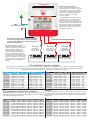
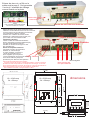
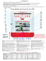
1
Pro Charge Ultra Instruction Manual
WARNING
HIGH VOLTAGE
This product requires a knowledge of both AC and DC
electrical installation. Please do not install nor attempt to
install this product unless you are qualified to do so. All effort
is made to make the instructions as safe as possible but it is
not possible to cover all electrical safety and installation
aspects. Sterling can only assume a certain basic knowledge
is held by the installer. Children or people with mental or
sensory incapabilities should be supervised to ensure
that they do not play with this appliance.
To Standards:
Pro
LTRA
UL 1236 SB
CSA C22.2-107.2
Tested to CE standards
EN61000-3-2 EN61000-3-3
EN55014-1 EN 55014-2
EN60335-2-29
CEC listed
Sterling Power
Charge U
CEC listed
DANGER
HIGH VOLTAGE
TO AVOID SERIOUS INJURY OR DEATH FROM ELECTRICAL
SHOCK. BEFORE PERFORMING ANY ELECTRICAL WORK
ENSURE YOU TURN OFF AND REMOVE ANY AC POWER
AND CHECK VOLTAGES TO MAKE SURE THE CIRCUIT IS OFF.
EN ISO 13297
Small Craft Directive
DANGER
EXPLOSION HAZZARD
BC
TO AVOID SERIOUS INJURY OR DEATH MAKE CONNECTIONS
IN A WELL VENTILATED ATMOSPHERE FREE FROM
EXPLOSIVE FUMES. IT IS ADVISABLE TO WEAR SAFETY
GOGGLES WHEN WORKING NEAR BATTERIES.
compliant
RoHS
DANGER
LOW VOLTAGE
TO AVOID SERIOUS INJURY OR DEATH FROM ELECTRICAL
BURNS & SPARKS ENSURE YOU DISCONNECT ANY DC
POWER AND CHECK VOLTAGES TO MAKE SURE THE CIRCUIT
IS OFF BEFORE PERFORMING ANY ELECTRICAL WORK.
CAUTION
HIGH TEMPERATURE
HOT SURFACES - TO REDUCE RISK OF BURNS DO NOT
TOUCH THE UNIT WHEN IN SERVICE.
ONLY CHARGE THE CHEMISTRY PROFILES WHICH ARE
COVERED BY THE PRESET VALUES OF THE UNIT.
IF CUSTOM SET, VALUES MUST ADHERE TO THAT OF THE
BATTERY MANUFACTURE. GETTING THE VALUES WRONG
COULD LEAD TO GASSING AND EXPLOSION OF BATTERIES.
ONLY USE THIS CHARGER WITH LITHIUM- LiFePO4 BATTERIES
IN CONJUNCTION WITH A Battery Management System FOR
FAILURE TO FIT A B.M.S. COULD RESULT IN A FIRE.
12V 60A model, all other units pro rata.
Input voltage range
90-270V 40-70Hz
Power Factor at 230V
0.95
Efficiency
88.5%
Full load current ( 110/230V )
10 /4.8
Ripple noise ( R.M.S. )
50mV
Ground leakage
0.75 mA
Generator / mains power required to run unit
(watts)
12V 10A approx 250 watts 2 outputs
12V 20A approx 300 watts 3 outputs
12V 30A approx 450 watts
12V 40A approx 600 watts
12V 50A approx 750 watts
12V 60A approx 900 watts
24V 20A approx 600 watts
24V 30A approx 900 watts
36V 20A approx 900 watts ( NOT UL LISTED)
48V 15A approx 900 watts ( NOT UL LISTED)
voltmeter accuracy
+/- 1.5%
ammeter accuracy
+/- 1%
Safety Certified by:
For Multi battery type and
voltages Complementary
addition:
Battery Chemistry Module (BCM).
Allows for multiple chemistry
charging simultaneously from
one charger ( different battery
types ) . Also allows for 24V
charging from 12V charger.
Read page 5.
PCU Top Functions:
1) 11 preprogrammed battery curves including LiFePO4.
2) 1 custom set, can be set from charger, no need for computer.
3) 2 x digital meters for current and voltage measurement.
4) 1 x power meter to show what reserve power left on the unit.
5) Active PFC, up to 0.99 pf, ensuring efficient power conversion
6) Synchronized rectification output as opposed to diode output (+10% efficiency)
7) High voltage de-sulphation cycle.
8) New, low activity, standby mode to increase battery life.
9) Battery health program.
10) Multiple speed fan control to reduce unnecessary fan noise.
11) Primary (processor digitally controlled) and an emergency backup.
12) 32 LED information panel.
13) Internal scan and systems check.
14) Remote control.
15) Small footprint and light weight.
16) Include battery temperature sensor.
17) USA CEC listed (default setting is on, CEC can be turned off). CEC
regulation stipulates that the charger is only on when necessary. This
reduces AC power consumption and lowers operational costs, while
maintaining healthy batteries.
18) % power reduction to allow unit to work with restricted input power.
19) Conforms to A.B.Y.C. drip test. Waterproof when water is dropped directly on
to the top of the unit ( +/ - 17 degrees ) if installed correctly (vertically).
20) The printed circuit boards are conformal coated for high humidity operations.
Installation
1) Install in cool dry well ventilated space.
2) This product has a high heat tolerance and can be installed in a engine room.
3) This product is ignition protected and can be installed near the batteries.
4) Charger MUST be installed vertically to allow for convection air flow and also in the vertical position
5) The product is drip proof.
6) The product will work in any position but we cannot guarantee the drip proof aspect (only vertically).
Quick LED feature guide
Pro
15
16
17
18
19
20
21
22
23
24
Charge ULTRA
Warm air
out
Sterling Power
GLOBAL A/C Input & Active Power Factor Correction
Progressive DIGITAL software control Charger / Powerpack
www.sterling-power.com
www.sterling-power-usa.com
AC Power
Auto Temp Control
0%
1 2 3
Charger Output
Absorption
Fast Charge
CHARGER MODE
System self test
De-sulphation
Battery Type
OK
Fault
SETUP
ENTER
100%
Safety Certified by: TUV
Built and tested to
UL 1236 SB
CSA C22.2-107.2
bc
Battery Health Program
Stand-by
Preset 2
Multi Speed Cooling
AUTO CONSERVATION MODES
RoHS
compliant
Amps
Volts
Active PFC
Preset 1
1
2
3
4
5
6
7
8
9
10
11
12
13
14
Open lead acid
Sealed lead acid
Float
CHARGE INFORMATION
DC Output Fault
DC Low Voltage
A.G.M
DC High Voltage Trip
GEL
High Charger temp trip
Lithium (LiFePO4)*
Calcium / Custom
To avoid serious injury or death from
electric shock. Before opening, turn
off the main AC power. Do not expose
Check Fan
*Lithium must be used in conjunction
with a lithium balancing system.
High current capable of causing
sparks burns and fires, always
High Voltage AC WARNING Low Voltage DC
Lithium battery Use
Fit this way up to
comply with UL
accordance and for
ABYC drip proofing
compliance.
this charger must not be used to
charge lithium battery cells by itself.
You cannot charge lithium cells on
their own. You must have a lithium
balancing device in conjunction with
the charger.
Cooling
Air flow
1) Ammeter, shows the total current being produced
by the charger
2) Voltmeter, showing the average voltage being
produced by the charger
3) Power meter, shows the % power being produced
by the unit and the remaining power available
4) AC power, shows the AC power is connected and
the product is live. LED flashes if power is available
but the unit is switched off ( see on/off later ) push
buttons. Setup and up arrow for 5 secs to activate.
5) Auto temp control, shows the battery temp sensor
is connected and operational. If sensor not
connected then the unit will default to a 20 deg C / 69
F charge curve.
6) Shows that the active PFC (power Factor
Correction is on)
7) Fan speed control, varies depending on temp, 3
speeds.
8) Standby, charger power system power
requirement very low, unit on low float voltage to
prolong battery life.
9) Fast charge unit on constant current mode.
10) OK, unit operating within normal parameters
11) Fault, fatal fault, needs returned for repair.
12) Battery type selector, shows which battery
charger curve in operation (adjustable).
13) Buttons to select charge options (see later in
instructions) also used to switch unit off or on in
conjunction with the setup button (see 14).
Off select button press down button for 5 seconds.
On select button press up button for 5 seconds.
14) Button to enter selections. Also, use to switch unit
on/off in conjunction with the up or down button.
15) Battery health program, unit doing a 21 day desulphation cycle.
16) Absorption, charger on initial charge cycle.
Preset 1 Profiles
Battery type
High Charge V
Flooded/Open Lead acid
14.8
Sealed Lead acid
14.4
AGM
Lead acid
14.4
GEL
Lead acid
14.0
LiFePO4-Lithium
13.8
Calcium / Custom
15.1
Equalization
15.5
17) De-sulphation cycle operational. For safety
reasons Only available when on open lead acid
battery type
18) Float, unit on float charge or power pack mode,
main charge complete.
19) DC output service, output working correctly.
20) DC output low voltage warning, either batteries
are very low / more power is being taken than the
charger can supply / or the charger is defective.
21) High voltage trip, the unit is defective and tripped
itself, or a high back DC voltage has been detected,
like a wind generator reg gone defective.
22) High charger temp, if the unit is positioned in too
hot an environment and over heated, or the fans
have failed.
23) Check fans, fans are thought to be defective.
24) Case screws to access the wiring of the product.
x 2 all voltages for 24V unit x 3 for 36V x 4 for 48V
Float Charge V
13.6
13.6
13.4
13.7
13.8
13.6
15.5
Maintenance V
12.8
12.8
13.0
13.2
13.2
13.2
Preset 2 Profiles
High Charge V Float Charge V Maintenance V
14.7
13.4
12.8
14.6
13.4
12.8
14.6
13.6
13.0
14.6
14.6
13.2
14.6
14.6
13.2
Your choice see custom setup in instructions
15.5
15.5
Pro
Charge ULTRA
Ground / bonding / earthing.
This is extremely important and often
overlooked there are, in effect, 3 grounds,
1) The earth wire ( AC input, the ground ).
2) the Chassis / bonding ground ( going to
a vehicle body / boats bonding system,
the bolt on the side of the charger )
3) the DC negative.
Sterling Power
Ground / Chassis
Boat grounding
In most installations all these will end up
at the same point. The AC power source
should be connect to the boat/vehicle
chassis (for safety). The chassis earth will
also go there, and the DC negative should
also go there. In affect, bonding the total
system together ensuring any fault to the
chassis will blow a fuse. This could vary
for steel/aluminium boats.
Earth /chassis
boats bonding
AC circuit breaker
Any outputs not being used should be linked
across to one that is, this is not a requirement
for these new models but is good practice as it
helps spread loads etc.
DC - Fuse selection, as per the
diagram each positive output from the
charger to the battery must be fused.
Choose a fuse that is about 20%
higher amperage rating than the
maximum rating of the charger, and
round it up. Remember, this fuse is
primarily protecting the cables and not
the product. E.g. a 20A charger would
have about a 25A fuse. A 60A charger
about a 75A fuse. A full range of fuses
and fuse holders are available from
Sterling.
DC fuse
DC fuse
DC fuse
20% larger
amperage than
charger output
20% larger
amperage than
charger output
20% larger
amperage than
charger output
_
+
12 or 24V battery bank
_
+
12 or 24V battery bank
_
+
12 or 24V battery bank
AC installation (input to charger)
Wiring, using ring or captive spade connections and a proper crimping tool attach the AC cables Live ( line ) Neutral and Earth / Ground. Repeat
the procedure for the breaker side of the install, support the cable every 18 inches / 0.5 m and protect from sharp edges when passing through
bulkheads and all other openings as per any standards which apply to the installation.
Europe
Model
PCU1210
PCU1220
PCU1230
PCU1240
PCU1250
PCU1260
PCU2420
PCU2430
PCU3620
PCU4815
AC cable size ( mm2 ) for cable length up to 15 m
110 volt
fuse/breaker
230 volt fuse/breaker
3 core 0.75 mm2 4 A
3 core 0.75 mm2 6 A
3 core 0.75 mm2 8 A
3 core 0.75 mm2 6 A
3 core 1.5 mm2 11 A
3 core 1.5 mm2 7 A
3 core 1.5 mm2 14 A
3 core 1.5 mm2 7 A
3 core 1.5 mm2 16 A
3 core 1.5 mm2 8 A
3 core 1.5 mm2 16 A
3 core 1.5 mm2 8 A
3 core 1.5 mm2 14 A
3 core 1.5 mm2 7 A
3 core 1.5 mm2 16 A
3 core 1.5 mm2 10 A
3 core 1.5 mm2 16 A
3 core 1.5 mm2 10 A
3 core 1.5 mm2 16 A
3 core 1.5 mm2 10 A
USA
Model
PCU1210
PCU1220
PCU1230
PCU1240
PCU1250
PCU1260
PCU2420
PCU2430
PCU3620
PCU4815
AC cable size ( AGM ) for cable length up to 50ft
110 volt
fuse/breaker
230 volt fuse/breaker
3 core 18 AWG 4 A
3 core 16 AWG 6 A
3 core 16 AWG 8 A
3 core 18 AWG 6 A
3 core 14 AWG 11 A
3 core 16 AWG 7 A
3 core 14 AWG 14 A
3 core 16 AWG 7 A
3 core 12 AWG 16 A
3 core 14 AWG 8 A
3 core 12 AWG 16 A
3 core 14 AWG 8 A
3 core 14 AWG 14 A
3 core 16 AWG 7 A
3 core 12 AWG 16 A
3 core 12 AWG 8 A
3 core 12 AWG 16 A
3 core 14 AWG 8 A
3 core 12 AWG 16 A
3 core 14 AWG 8 A
IMPORTANT
The closer to the batteries you fit the charger the better. Not only do you save
Choosing cable. unlike AC conductors, DC is very sensitive to voltage drop. expensive cable you also get better performance from the charger. The cable
The longer the cable runs the larger the cable thickness needs to be. Ensure should be properly rated to 105 deg C fire resistant. Do not use solid cable or
only quality fire retardant cable is used.
speaker wire.
DC installation (output from charger)
Europe
Model
PCU1210
PCU1220
PCU1230
PCU1240
PCU1250
PCU1260
PCU2420
PCU2430
PCU3620
PCU4815
DC Charge cable size ( mm2 ) for cable length
1m
2m
3m
4m
5m
6m
2.5 mm2 4 mm2 6 mm2 10 mm2 10 mm2 16 mm2
4 mm2 10 mm2 16 mm2 16 mm2 25 mm2 25 mm2
6 mm2 6 mm2 25 mm2 35 mm2 50 mm2 50 mm2
10 mm2 16 mm2 25 mm2 35 mm2 50 mm2 50 mm2
10 mm2 25 mm2 35 mm2 50 mm2 50 mm2 n/a
n/a
16 mm2 25 mm2 50 mm2 50 mm2 n/a
4 mm2 10 mm2 16 mm2 16 mm2 25 mm2 25 mm2
6 mm2 6 mm2 25 mm2 35 mm2 50 mm2 50 mm2
4 mm2 10 mm2 16 mm2 16 mm2 25 mm2 25 mm2
4 mm2 10 mm2 16 mm2 16 mm2 25 mm2 25 mm2
USA
Model
PCU1210
PCU1220
PCU1230
PCU1240
PCU1250
PCU1260
PCU2420
PCU2430
PCU3620
PCU4815
DC Charge cable size ( AWG ) for cable length
5 ft
10 ft
15 ft
20 ft
25 ft
30 ft
16 AWG 14 AWG 12 AWG 10 AWG 10 AWG 10 AWG
14 AWG 10 AWG 10 AWG
8 AWG
6 AWG 6 AWG
12 AWG 10 AWG 8 AWG
6 AWG
6 AWG 4 AWG
8 AWG 6 AWG
6 AWG
4 AWG 4 AWG
10 AWG
6 AWG 6 AWG
6 AWG
4 AWG 2 AWG
8 AWG
8 AWG
6 AWG 4 AWG
4 AWG
2 AWG 2 AWG
14 AWG 10 AWG 10 AWG
8 AWG
6 AWG 6 AWG
12 AWG 10 AWG 8 AWG
6 AWG
6 AWG 4 AWG
14 AWG 10 AWG 10 AWG
8 AWG
6 AWG 6 AWG
16 AWG 14 AWG 12 AWG
8 AWG
6 AWG 6 AWG
Remove the 2 screws on the bottom
of the front cover marked number 24
on the previous pages quick guide
this will reveal the main wiring area.
PCU 12V 10A & 20A models have ring
terminal screw connectors as depicted above.
N.B. the 10A model has only 2 outputs, all
other models have 3 outputs.
High Voltage
AC cover plate
and clamp
DC cable clamp
Remove the 2 screws on the AC area and the 3 screws on
the DC clamps to enable the appropriate wires to
be attached. AC input 90-270 volts.
Ensure secure connections and correct crimping
tools are used.
DC 12V or 24V depending on unit.
Battery temperature sensor connection
Remote control
Remote control
Insert the Sterling remote control
into the remote socket ( telephone type )
Please note that when the remote is inserted the
front program controls on the local panel no longer
operate, control is in the remote. Remove the
remote to use local controls.
Battery Temperature sensor
Connect the battery temp
sensor to the position
Live Neutral
as shown, connect the
Live Neutral
sensor end to the negative stud
terminal on one of the batteries
which you think will be in the hottest environment.
A
FUSES
DC
PCU 12V / 30-60A &
24V 20-30A have bolt
terminals as depicted above
rather than screw terminals.
Earth ( European )
Ground ( USA )
1
2
3 Common Negative
red red red Black (Europe) Yellow (USA)
Pos terminals on
3 x battery banks
1
5 [130]
8
260 mm
10 1/4 inch
24V
30A iQ
Pro
Nautic
12-60
5
3 [93]
8
90 mm
3 ½ inch
81
2 [215]
Cut out
90 x 62 mm
44 mm
1 3/4 inch
215 mm
8 ½ inch
dimensions
in inches
and ( mm )
3
12 [315]
8
85 mm
3 3/8 inch
ProMariner
12V 50-60A
85 mm
3 and 3/8 inch
90 mm
3 ½ inch
12V 10-40A
24V 20A
5
38 [93]
3
7 4 [198]
198 mm 7 3/4 inch
( Optional ) Battery Chemistry Module
Multi battery chemistry and voltages output options
Battery Charger Chemistry Modification Module
Another great idea from Sterling. Patent Pending: GB1204145.5
What was the issue which led to the invention of this device?
A lot of new installations on modern boats require different chemistry and
even different voltage levels. For instance, you may have a 12V charger
but a 24V bow thruster or vice versa. You may also have an open lead acid
battery banks and a Lithium. This causes impossible challenges for a
standard battery charger or you may simply have one battery bank a long
way from another bank requiring very expensive cable runs to prevent
voltage drop, ( no longer a problem with the BCM ).
The solution
The new Sterling Battery Chemistry module has a unique approach to solving
this problem. We effectively place in a box a voltage booster and the output
stage from a digital charger. This means that the new device can be added to
any of the output terminals of our Pro Charge Ultra (or can be used as a add
on to most other competitor companies multiple output charger). This will
allow the main 3 (or more) output charger to be set at the lower chemistry
voltage for the likes of Gel (14.1V absorption), then, by adding the new Sterling
Multi chemistry module to one of the outputs (must be connected to an output of
a current limiting charger and cannot be connected direct to a battery. One can
adjust that output to a totally different charging chemistry profile. The output
voltage and charging curves are independent of the charger’s input voltage.
This enables a totally different chemistry to be selected. This gives all the
advantages of the multi chemistry charger without the huge extra cost, and can
be simply retro fitted to any multi output battery charger (within the limitations of
the product).
Advantages of this product
1) Easy to install.
2) Fits our products and most of our competitors multiple output chargers.
or converts a single output charger into a multiple output charger.
3) 12-12V, 12-24V, 24-24V and 24-12V models.
4) 8 selectable independent latest battery chemistries to chose from and a desulphation cycle, also LiFePO4 cycle .
5) Battery temperature compensation and high battery temperature trip.
6) Remote battery sense compensate for cable voltage drop.
7) 6 LEDs projecting over 20 individual charge and warning information
events.
8) Fail safe, reverts to basic charge function - about 1V less in event of a
failure. Product can be replaced/repaired at convenience.
9) High battery temperature "daisy chain" trip ( optional ). This allows every
battery to be monitored and the unit can be switched off in the event of battery
overheating - causing high battery temperature related problems.
10) Ignition fed generator to link in with sterling Pro Split R alternator splitter,
this allows the output to be further split.
11) Remote control available as an optional extra.
Which model suits my needs. Ensure that your current charger’s output is
equal to or less than the rating of the product. I.e. a 12V 60A module can be
used on any charger up to 12V 60A .
Do you want to simply add a chemistry option. I.e. a different battery type
but maintain the same base voltage i.e. 12V or 24V. In which case the
BCM1260 will allow a totally separate battery type in the 12V charger.
Do you want a different base voltage and battery type. I.e. you have 12V
charger but you want to also charge a 24V battery bank. In this case, go for the
BCM 12V-24V option this allows for the different voltage and chemistry
Long cable runs. You may have a very long cable run from the main charger
to an important auxiliary battery. Simply add one off these units at the end off
the run to boost up the voltage to the required battery type, thus reducing
cable thickness requirement and hence cost .
Example - A 12V starter battery bank (sealed lead acid).
A Lithium main battery bank and a 24V open lead acid Bow Thruster.
Pro
Battery Chemistry module
and optional remote control
(remote control not required for operation)
Charge ULTRA
Absorption
Condi
Sterling Power
H Charge
Float
Sterling Power Products
V
12.2
In / Unit Bat - Chem - Unit
GLOBAL A/C Input & Active Power Factor Correction
Audible alarm on/off
hold >5 sec
Temp
Volts
Menu
Alarm
Unit on/off
Setup
Select hold > 5 sec
Out / Rem
Batt.
Fault
Earth /chassis
boats bonding
Main Charger
set to 14.4V
sealed lead acid
Battery Chemistry
module 2
set to 24V AGM
Battery Chemistry
module 1
set to LiFePO4
12V
_
12V
+
12V Sealed engine
starter Battery bank
_
24V
+
12V LiFePO4 Lithium
Main Battery bank
_
24V Bow thruster
Battery bank AGM
+
NSTALLATION OF THE BATTERY CHARGER
Position the charger in a cool, dry and well ventilated space, ensuring a reasonable airflow
around the charger. Do not install in a cupboard or sealed compartment.
Charger MUST be installed vertically.
Install as close to the batteries as possible, preferably within 2 meters of the batteries.
To obtain maximum waterproof/ingressproof rating (IP42) mount the charger vertically.
However, the unit will work just as well in any fastening orientation so long as it is dry.
With regards charging cooling, the unit has thermostatically controlled force draft cooling
and is thus able to remain cool whether fastened in any orientation.
Always isolate the AC power before working on it
- Before switching on the charger it is important to set up the battery type. Please choose a
battery type from the table (at the bottom of page 2). There are so many different profiles,
and battery companies change them all the time. It is impossible to keep up, so in order to
assist our customers we offer the option of preset battery types: Flooded, sealed, AGM,
Gel, LiFePO4, calcium and custom. Each type has 2 preset algorithms, for instance: Gel
preset 1 is the USA Gel spec (absorption 14.0V and float 13.7V) and Gel preset 2 is the
Europe Gel spec (absorption 14.4V and float 13.7V). We also provide the charge voltages
related to this cycle. In most cases these are correct; however, if in doubt install on the lower
voltage setting until you have checked with your battery supplier.
In the event of different battery chemistry types. If you are only using the Pro Charge
Ultra then the lowest battery voltage type must be selected. Never charge a battery
on a higher setting than it should. If you require different battery chemistries then
look at our Battery Chemistry Module (page 5). It allows for different battery
chemistry charging .
If a bespoke battery is being used then use the CUSTOM setting. This gives the user the
ability to set their own absorption/float voltages.
Connect the cables as in the diagram. Ensure that all the terminals are used. In the event of
only one battery being charged, connect the surplus positive output to another used output.
This ensures correct regulation. Failure to do this will reduce the charging performance.
IMPORTANT: Always connect the cables to the charger first then run them to the batteries.
Never connect to the batteries first and then run to the charger.
Pre setup Mode overview CEC mode (BC) and Power Supply mode (PS)
This Pro Charge Ultra is now constructed with the most power efficient technology available for a
battery charger providing both charging and maintaining capability. This overall design and
efficiency will reduce the overall operating cost of the unit by conserving AC power when it is
not needed. Meanwhile, it provides perfect battery maintenance and overall superior DC
charging performance. The combination of sophisticated hardware and software includes
the detection of the presence of one or more batteries connected to the Pro Charge Ultra.
NOTE: If there is no battery connected, the battery charger will not operate in the new
default bc mode, however this unit can easily adjusted to the older PS mode which will allow
the unit to work in power supply mode. See PS (Power Supply) mode selection below.
Both modes
PS mode (power supply). is the way all our chargers have been working up to date, it means the
unit will work even if not connected to a battery bank.
bc mode (CEC mode). This is a new ecological regulation brought on by the Californian Energy
Commission (CEC). It is being adopted by more and more states, we feel that it is such a
reasonable regulation that it will eventually be adopted world wide. Essentially, at present,
when you charge your phone and your batteries are full then the charger continues to
operate. This charger uses a small amount off power simply doing nothing. If you multiply
this by millions of households all doing the same thing there is a lot of wasted energy. So, by
turning off the charger you could potentially save numerous power stations. It's a lot more
complex for a marine battery charger which has to charge the batteries then run the boat as
well. However, we have devised a complex algorithm to monitor the power consumption
and when it drops below a certain amount we switch off the charger and transfer the
monitoring to a very low power operational circuit. If, or when, the battery voltage drops a
little our monitoring circuit would recognises this and re-engage the unit. This will maintain
the batteries at a full state and operate as a power pack.
What difference will this make ?
1) It is now legal in California and other adopted states. The CEC mode future proofs.
2) If you power for your system is monitored a reduction in the power used for the equipment
should be noticed ( you can tell you daughter your now green ).
The bottom line as a user on a day to day operation on 99% off installations it will not be a
noticeable feature, it would only prove to be a problem if you want to use the charger as a
power pack. I.e. not connected to the battery banks. In which case, change the mode.
In the event you would like to use your Pro Charge Ultra as a power supply without a
battery in the system you may do so simply by selecting the Power Supply (PS) mode
during the initial startup phase. This mode will allow the charger to be used as a power pack
for 12V or 24V (model specific).
Selecting PS (Power Supply) Mode Operation During AC Power On Startup overview
When AC power is applied or when the Self Test function is initiated the numerical displays
will first display “888” to indicate all segments of the displays are working. Then the display
will indicate either “bc” (Battery Charger) or “PS” (Power Supply) for 7 seconds. You can
change the required settings during this time frame if required ( see below for instructions ).
After 7 Seconds the battery charger will default to its “bc” (Battery Charger) mode of
operation or the previously programmed function.
Note: The battery charger will default to the Sealed Battery Type Charge profile (for both “bc” and
“PS” modes of operation). You may also select any of the other battery type profiles in this
mode. See Selecting Battery Type in the programming section of this manual.
If during the AC Power start-up you would like to select the “PS” (Power Supply) mode of operation
you may do so during the 7 seconds window while the display is indicating "bc" by:
1) Push either the
or
key to toggle between "bc" and "PS"
2) While the display reads "PS" press Setup/Enter
Setup
Enter
Operating Instructions
From main charge only (not remote control)
On/off the unit can be switched off using the controls on the charger main control panel ( it can
also be switched on/off on the remote ( see later ) )
Unit On press setup and the up button, hold for 5 sec.
Setup
Enter
Setup
Unit Off press setup / enter and down for 5 sec. Enter
The blue AC power LED will flash to show the power is available but the unit is not activated.
SELECTING BATTERY TYPE
To select a battery type/charging profile perform the following:
1.
Press and hold the “Setup/Enter” button for 6 seconds, then release the button.
2.
The current battery type and Voltage/Amperage displays will flash. The voltmeter
and ammeter will now display voltage, the left hand screen (marked voltmeter) will
show the high charge voltage setting (absorption) and the right hand screen
(marked ammeter) will show the low charge / float / power pack voltage setting.
3.
Use the “↑” and “↓” keys to scroll through all the different battery types. The LED
display on the charger in the battery type section will move through the different
types.
4.
The voltage and amp readout will display the absorption/conditioning and float
voltages for each profile highlighted.
5.
Press the “Setup/Enter” button to confirm selection, the LED will remain solid or
leave for 30 seconds and the selection will be locked in automatically.
ADJUSTING THE CUSTOM BATTERY TYPE SELECTION
WARNING: *Damage can result to your batteries from improper use of this custom setting. Any
damage experienced while using this setting is the responsibility of the user and not
covered by any Sterling warranty. ALWAYS consult the battery manufacturer if you are
unsure of the battery chemistry and charge profile required.
1.
Follow above steps and select the “Custom” option on the battery
type display and press enter to enter it.
2.
The “Fast charge & Absorption” LEDs will be blinking, indicating you are in the
adjustment mode.
3.
The left hand meter will blink and the right hand meter will go out. The numbers on
the left hand meter will be the high voltage setting. Adjust as required by using the
“↑” and “↓” to select voltages up to 15.1V. Press enter when you have selected
the correct voltage. Then right hand screen will flash now flash - this is the float
voltage settings, again, use the arrows to set this voltage and press enter to finish.
NOTE: During this process, real-time voltage and amperages will not be
displayed.
SELF TEST MODE
1.
Press and hold the “Setup/Enter” and the “↑” and “↓” buttons simultaneously for
10 seconds then release.
2.
The “Self Test” LED will flash until the test is complete.
3.
OK or Fault LED's will be displayed, see the Troubleshooting section if the Fault
LED is illuminated.
FACTORY RESET
To return the unit to original factory settings (Sealed Lead Acid)
1.
Enter battery type selection as above.
2.
Use the “↓” key until you leave the battery type LED panel then the de-sulphation
light will flash, continue to the next setting. The 2 x voltmeters will display “FAC”
“DEF” for factory default.
4.
Press the “Setup/Enter” button to confirm selection, the charger will reboot.
EQUALIZATION / DE SULFATION MODE (can only be activated in open lead acid mode)
This mode is only recommended for open lead acid batteries and will only activate when
in open lead acid mode, its can be extremely dangerous to use in other battery
types as in essence we will over charge the battery to "blow" the sulfation off the
plates. This process generates more gas than normal and, as such, the battery
may need topping up after the process. It is NOT recommended on batteries which
cannot be topped up.
Setup
1) Press and hold the setup key for 5 secs Enter then use the
or
to select
the equalization LED ( while on flooded battery setting ), when selected the LED
will flash.
2) Once selected hold both
and
for 3 seconds plus, then release.
3) The LED will change from flashing to solid, putting the unit into equalising setting for
240 minutes and remain solid for the full time frame.
4) Once complete, the charger will revert back to the previous charger setting.
POWER LEVEL ADJUSTMENT
1.
Hold the“↑” and “↓” buttons simultaneously for about 20 seconds.
2.
Volts will display “PL” for Power Level, and the amps 100 for 100%
3.
Press the “↓” to adjust the amperage display from 100, 75, 50, 25% output.
4.
Press the “Setup/Enter” button to confirm selection.
NOTE: If no action is taken after 15 seconds, the unit reverts to 100% power.
Pro Charge Ultra Remote Control
3.
m. Total Run Time
n. Software Revision
Once the remote is displaying the desired function press
Setup / Enter button once to show this functions detail. To
change selection repeat and scroll through to the required
information.
Button Functions:
d.
Both the ?or ? are used for toggling up and down through the menu options
after the Setup/ Enter button has been pressed
B
Additional Charger Modes
FORCE TO READY/FLOAT Maintenance = “Hold” 10 Seconds
The force to float mode is not necessary for standard operation.
1. Hold the ? button down for 10 seconds.
2. The display will stop scrolling and a “Beep” sound to
confirm entered into this mode after button released.
3
The charger will go to float mode and will remain in
float until battery voltage drops to a level where
Charge is require or until power is recycled.
If you do use this function to get out off it you must
switch the charger off at the main a/c power source
to reset this.
to install
Slide parts A to expose screw holes.
For flush mount, remove part B.
For surface mount, keep part B.
After installation, replace parts A.
A
Operation:
POWER LEVEL ADJUSTMENT = “Hold” 15 Seconds
Power, Start Up and Language Selection:
a.
If breaker is turned on and charger has AC power the remote is
lit with the backlight on.
b. “Language Select: English” (factory default) will display and
flash for 5 second. The operator can select the language during
these 5 seconds by pressing the UP or DOWN keys to toggle
through all of the available languages (English, German,
Spanish, Italian, French) and then press SETUP/ENTER key to
confirm.
If no selection is made within these 5 seconds, the default
language shall be selected.
(If you wish to change the language at a later date, refer to
‘language selection’ section below).
c. Charger mode will displayed (Charge, Conditioning, Ready)
along with voltage and amperage until another mode is selected.
I. Hold “?”
both “?”down together for 15 seconds.
II. The display will stop scrolling and a “Beep” sound to confirm
entered into this mode after buttons released.
III.. Press “?”
to adjust the Amperage display from 100, 75, 50, 25%
output.
IV. Once Power Level is desired confirm the selection by pushing
“Setup/ Enter”.
V. If no actions are taken in 15 seconds the unit reverts to 100%
power.
VI. Remote will display Power level at % that is selected (100, 75,
50, 25 for one second on, then one second off, then on
displaying Voltage and Amperage at that selected power level).
VII. Once a power reduction is selected it remains permanent until
re-programmed again.
VIII. To readjust the power level follow steps 1-5 making sure to
confirm 100% to resume normal operation.
IX. When in power level mode selection display (Power Level 50%
and output voltage/ current.
Button Operation – with AC power applied to the charger
a.
(Backlight) Button Operation:
1. Press On-Off for about 1 sec the backlight will turn
OFF. Warning If you hold for more than 4 sec the
complete charger will switch off
2. Press On-Off for about 1 sec the backlight will turn
back ON.
b.
(Alarm) Button Operation:
1. Press Alarm to turn audible alarm OFF.
2. Press Alarm to turn audible alarm ON.
c. (Setup/ Enter) Button Operation
***(If not selection is made within 10 seconds charger defaults to prior
setting).
1.
Press the Setup/ Enter button once
2. This will now allow you to toggle through all available
functions using the ?or ?
a.
b.
c.
d.
e.
f.
g.
h.
i.
j.
k.
l.
Scrolling – (Must push Setup/ Enter to confirm)
= will display all of the below one at a time for 4
seconds automatically scrolling through the menu
functions.
Charger Name
Charger Status (Same display shows both)
i. Mode displaying (Charging,
Conditioning or Ready)
ii. Output Voltage
iii. Output Current
Battery Type Selection (Flooded Preset 1)
Time to Absorption
Run time during this session
Current Set Power Level should be 100% unless
in Power Level mode. If a different Power Level
is selected the charger will read 100, 75, 50,
25%.
Battery Temperature
Charger Temperature
Transformer Temperature
Faults
i. Over Voltage
ii. Under voltage
iii. Battery Over Temperature
Company Information
Setup
Enter
SYSTEM SELF TEST MODE = “Hold” 8 Seconds
I. To test the chargers system hold all three (Setup/ Enter, ?,?)
buttons down for 5 seconds,
II. The display will stop scrolling and a “Beep” sound to confirm
entered into this mode after buttons released.
III. The charger will “Self Test” and if normal display “System OK” if
not a failure or failures will be displayed. If more then one failure
exists you can push ?or ? to view the failures.
IV. Press Setup/Enter to go to other functions when complete.
Alarm
Setup
Enter
FACTORY RESET = “Hold” 3 Seconds
I. To restore the Factory Defaults “hold” Alarm, Setup/Enter, and ?,
?down for 3 seconds.
II. The charger will then restart with the factory defaults.
Output ON/OFF function (For Sterling version only)
a. Press and hold Power button for 4 second to turn
the charger output OFF
b. When charger is OFF, press Power button to turn
the charger output ON
How to change language once a language has been selected or
defaulted to English
1. Press and hold SETUP/ENTER key for 3 seconds, the display
will go to language selection mode.
2. Remote will display the current language and flashing for 5
seconds.
3. Select language within these 5 seconds by pressing UP or
DOWN key to toggle through all available language
4. Press SETUP/ENTER key to confirm
5. If no selection is made within these 5 seconds, the language will
keep as default or previous setting unchanged.
6. Remote will go back to normal operation
7. The display sequence of language is English, German, Spanish,
Italian, French
IIMPORTANT SAFETY INSTRUCTIONS
SAVE THESE INSTRUCTIONS - this manual contains important safety instructions for
the Pro Charge Ultra
1) Do not expose this unit to rain or snow.
2) Use of attachments not recommended or sold by Sterling Power will void warranty and
may result in the risk of fire.
SHOCK OR PERSONAL INJURY.
3) Do not operate the unit if it has been dropped or visibly damaged in any way
4) Do not disassemble the unit. If service or repair is required please contact Sterling at:
www.sterling-power.com or www.sterling-power-usa.com
5) To reduce the risk of electrical shock, remove connection to AC shore / station power and
DC connections prior to maintenance or cleaning.
6) Turning off controls WILL NOT reduce this risk.
7) Use of extension cord should not be used unless absolutely necessary. If an extension
cord must be used, make sure:
a) That pins on plug of extension cord are the same number, size and shape of those of the
plug on the charger.
b) That the extension cord is properly wired and in good electrical condition.
c)That wire size is large enough for AC ampere rating of charger as specified in table
(page3)
6) Do not operate charger with damaged cord or plug - replace the cord or plug immediately.
7) Do not operate charger if it has received a sharp blow, been dropped, or otherwise
damaged in any way; take it to a qualified serviceman.
8) Do not disassemble charger; take it to a qualified serviceman when service or repair is
required.
9)To reduce risk of electric shock, unplug charger from outlet before attempting any
maintenance or cleaning. Turning off controls will not reduce this risk.
WARNING – RISK OF EXPLOSIVE GASES.
WORKING IN THE VICINITY OF A LEAD-ACID BATTERY IS DANGEROUS. BATTERIES
GENERATE EXPLOSIVE HYDROGEN GAS DURING NORMAL BATTERY OPERATION.
FOR THIS REASON IT IS OF UTMOST IMPORTANCE THAT EACH TIME BEFORE USING
YOUR CHARGER YOU READ THIS MANUAL AND FOLLOW THE INSTRUCTIONS
EXACTLY.
To reduce the risk of a battery explosion, follow these instructions and those published by the
battery manufacturer and any equipment you intend to use in the vicinity of the battery(s).
Carefully review the cautionary markings on this equipment.
SPARK – Be very cautious about dropping metal objects such as screwdrivers and
wrenches onto a battery. This could short-circuit the battery and immediately cause a spark
that may result in a fire or explosion.
REMOVE – All personal metal items such as rings, watches, bracelets, etc. when working
near a battery. A battery can produce a short circuit current high enough to weld a ring or any
other metal causing serious burns.
DRY CELL BATTERIES – Never use the battery charger feature to charge dry cell batteries
that are commonly used with home appliances i.e. a cordless power drill battery. These
batteries may burst and cause injury to persons and damage property.
FROZEN BATTERY – Never charge a frozen battery.
UNPACKING AND INSPECTION – Thoroughly inspect your unit.
11. PERSONAL PRECAUTIONS
a) Consider having someone close enough by to come to your aid when you work near a
lead-acid battery.
b) Have plenty of fresh water and soap nearby in case battery acid contacts skin, clothing, or
eyes.
c) Wear complete eye protection and clothing. Avoid touching eyes while working near
batteries.
d) If battery acid contacts skin or clothing, wash immediately with soap and water. If acid
enters eye, immediately flood eye with running cold water for at least 10 minutes and get
medical attention immediately.
e) NEVER smoke or allow a spark nor flame in vicinity of battery or engine.
GROUNDING AND AC POWER CORD CONNECTION
a) Charger should be grounded to reduce risk of electric shock. Charger is
equipped with an electric cord having an equipment-grounding conductor and
a grounding plug. The plug must be plugged into an outlet that is properly
installed and grounded in accordance with all local codes and ordinances.
DANGER - Never alter AC cord or plug provided - if it will not fit outlet, have
proper outlet installed by a qualified electrician. Improper connection can result
in a risk of an electric shock.
b) For grounded, cord-connected battery chargers with an input rating less than
15A and intended for use with a global AC input (90V - 270V).
This battery charger is for use with a global AC input (90V - 270V) and has a
grounding plug. A temporary adaptor, as shown (figure is overleaf), may be
used to connect this plug to a two-pole receptacle, if a properly grounded outlet
is not available. The temporary adapter should be used only until a properly
grounded outlet can be installed by a qualified electrician.
DANGER - Before using adapter as illustrated, be certain that center screw of
outlet cover plate screw with a longer screw that will secure adapter ear or lug to
outlet cover plate and make ground connection to grounded outlet.
c) For all other grounded, cord-connected battery chargers:
f) Be extra cautious to reduce risk of dropping a metal tool onto battery. It might spark or shortcircuit battery or other electrical parts that may cause explosion.
g) Remove personal metal items such as rings, bracelets, necklaces, and watches when working
with lead-acid battery. A lead-acid battery can produce a short-circuit high enough to weld a ring or
the like to metal, causing a severe burn.
h) Use charger for charging a LEAD-ACID battery only. It is not intended to supply power to a low
voltage electrical system other than in a starter-motor application. Do not use battery charger for
charging dry-cell batteries that are commonly used with home appliances. These batteries may
burst and cause injury to persons and damage to property.
12. PREPARING TO CHARGE
a) if necessary to remove battery from vehicle to charge, always remove grounded terminal from
battery first. Make sure all accessories in vehicle are off, so as not to cause an arc.
b) Be sure area around battery is well ventilated while battery is being charged.
c) Clean battery terminals. Be careful to keep corrosion from coming in contact with eyes.
d) Add distilled water in each cell until battery acid reaches level specified by battery
manufacturer. Do not overfill. For a battery without removable cell caps, such as valve regulated
lead acid batteries, carefully follow manufacturer’s recharging instructions.
e) Study all battery manufacturer’s specific precautions while charging and recommended rates
of charge.
f) Determine voltage of battery by referring to battery manufactures owner’s manual and make
sure that output voltage selector switch is set at correct voltage. If charger has adjustable charge
rate, charge battery initially at lowest rate.
13. CHARGER LOCATION
a) Locate charger as far away from battery as DC cables permit.
b) Never place charge directly above battery being charged from battery will corrode and damage
charger.
c) Never allow battery acid to drip on charger when reading electrolyte specific gravity or filling bat
t ery.
d) Do not operate charger in a closed-in area or restrict ventilation in any way.
e) Do not set a battery on top of charger.
14. DC CONNECTION PRECAUTION
a) Connect and disconnect DC output clips only after setting any charger switches to “OFF”
position and removing AC cord from electric outlet. Never allow clips to touch each other.
15. FOLLOW THESE STEPS WHEN BATTERY IS INSTALLED IN VEHICLE/BOAT. A SPARK
NEAR BATTERY MAY CAUSE BATTERY EXPLOSION. TO REDUCE RISK OF A SPARE
NEAR BATTERY.
a) Position AC and DC cords to reduce risk of damage
b) Stay clear of fan blades, belts, pulleys, and other parts that can cause injury to persons.
c) Check polarity of battery posts. POSITIVE (POS,P,+) battery post usually has larger diameter
than NEGATIVE (NEG,N,-) post.
d) Determine which post of the battery is grounded
e) For negative-grounded, connect POSITIVE (RED) clip from battery charger to POSITIVE
(POS,P,+) ungrounded post of battery. Connect NEGATIVE (BLACK) clip to vehicle chassis or
engine block away from battery. Do not connect clip to carburetor, fuel lines or sheet-metal.
Connect to a heavy gauge/gage metal part of the frame or engine block.
g) When disconnecting charger, turn switches to off, disconnect AC cord, remove clip from vehicle
chassis, and then remove clip from vehicle chassis, then remove clip from battery terminal.
h) See operating instructions for length of charge information.
16. FOLLOW THESE STEPS WHEN BATTERY IS OUTSIDE VEHICLE. A SPARK NEAR THE
BATTERY MAY CAUSE BATTERY EXPLOSION. TO REDUCE RISK OF A SPARK NEAR
BATTERY:
a) Check polarity of battery posts. POSITIVE (POS, P, +) battery usually has a larger diameter
than the NEGATIVE (NEG,N,-) post.
b) Attach at least a 24-inch-long 6-gauge (AWG) insulated battery cable to NEGATIVE (NEG, N, -)
c) Connect POSITIVE (RED) charger clip to POSITIVE (POS, P, +) post of battery.
d) Position yourself and free end of cable as far away from battery as possible - then connect
NEGATIVE (BLACK) CHARGER CLIP to free end of cable
e) Do not face battery when making final connection.
This battery charger is for use on a circuit having a nominal rating more than 90V
(or This appliance is rated more than 15A and is for use on a circuit having a
global AC input (90V - 270V) and is factory fitted with a specific electric cord and
plug to permit connection to an acceptable electric circuit. Make sure that the
charger is connected to an outlet having the same configuration as the plug. No
adapter should be used with this charger.
d) For a permanently connected battery charger:
GROUNDING INSTRUCTIONS - This battery charger should be connected to a
grounded, metal, permanent wiring system; or an equipment-grounding
conductor should be run with circuit conductors and connected to equipmentgrounding terminals or cable on battery charger. Connections to battery charger
provided with a grounding pin:
e) For a direct plug-in battery charger provided with a grounding pin:
CAUTION - Risk of fire or Electric Shock. Connect battery charger directly to
grounding receptacle (three-pong). An adapter should not be used with battery
charger.
f) For a direct plug-in battery charger having a tab for semipermanent
installation: Use only duplex receptacle having center screw; Secure unit in
place by receptacle cover screw; and CAUTION and the following or equivalent:
Risk of Electric Shock or Fire. Disconnect power to receptacle before installing
or removing unit. When removing receptacle-cover screw, cover may fall across
g) For a commercial battery charger that is intended to be permanently
installed and un-tampered with, the charger should be installed so that it is
not likely to be contacted by people.
DAMAGE – If any parts are missing or damaged, or the unit has been
damaged in shipping contact Sterling, do not take it back to the place of
purchase as we can offer a faster service.
Charger Fault ( Service ) Conditions
LED Label
LED Colour
Fault
Reverse Polarity
Red
Indicates a reverse polarity situation
Check DC Connections, ensure positive + ( RED) and negative - (Black and
/ or Yellow) connections are attached accordingly , also check DC fuses,
DC Volts Low
Amber
DC system V is less than 11V (x2 for 24v)
Wait for battery system voltage to rise over 11.0V and, if not, check and
replace defective batteries.
DC Volts High
Red
Indicates a high DC voltage from an external
source such as a failed alternator or wind
generator
Using a voltmeter check the voltage at the charger then switch off engine
( stop alternator ) then other charging sources to establish what is causing
the high voltage.
Charger High Temp Amber
Charger has shut down due to High temp
Generally this indicates that the unit has been installed in an area of very
high ambient temperature. This unit is designed to be used in a engine room
up to 45-50 Deg C, the unit will operate in higher ambient temperatures but
will reduce it performance off the product, We recommend an ambient off no
more than 50 Deg C. The other possibility is that the internal fan may have
failed, please listen to ensure the fan is running as one would expect the fan
to be on max speed in this fault condition so if quiet this could be the problem.
Check Fan
Red
Fan Failure
Ensure that the cooling fan can move freely and that no debris is blocking the
fan movement, the fan should come on during the start up sequence to prove
it works, any persistent fan problems may require servicing.
Fault
Red
Indicates a fault
Possible internal DC fuse blown, Please contact Sterling for service options.
Auto Temp Control Red Flash High Ambient causing power reduction
to sustain output.
See charger high temperature above .
Grounding Methods
Charger Fault ( Service ) Conditions
LED Label
LED Colour
Fault
Reverse Polarity
Red
Indicates a reverse polarity situation
Check DC Connections, ensure positive + ( RED) and negative - (Black and
/ or Yellow) connections are attached accordingly , also check DC fuses,
DC Volts Low
Amber
DC system V is less than 11V (x2 for 24v)
Wait for battery system voltage to rise over 11.0V and, if not, check and
replace defective batteries.
DC Volts High
Red
Indicates a high DC voltage from an external
source such as a failed alternator or wind
generator
Using a voltmeter check the voltage at the charger then switch off engine
( stop alternator ) then other charging sources to establish what is causing
the high voltage.
Charger High Temp Amber
Charger has shut down due to High temp
Generally this indicates that the unit has been installed in an area of very
high ambient temperature. This unit is designed to be used in a engine room
up to 45-50 Deg C, the unit will operate in higher ambient temperatures but
will reduce it performance off the product, We recommend an ambient off no
more than 50 Deg C. The other possibility is that the internal fan may have
failed, please listen to ensure the fan is running as one would expect the fan
to be on max speed in this fault condition so if quiet this could be the problem.
Check Fan
Red
Fan Failure
Ensure that the cooling fan can move freely and that no debris is blocking the
fan movement, the fan should come on during the start up sequence to prove
it works, any persistent fan problems may require servicing.
Fault
Red
Indicates a fault
Possible internal DC fuse blown, Please contact Sterling for service options.
Auto Temp Control Red Flash High Ambient causing power reduction
to sustain output.
See charger high temperature above .
MAINTENANCE
This unit is solid state software controlled and requires no constant
adjustments or attention, however, the following items should be checked:
1) On start up ensure the panel shows no fault LEDs.
2) On start up check the conditions of the fuses and ensure there is no
discolouration or corrosion round the fuse, also, check that the breaker will
manually trip and reset.
3) On start up check the fans cooling flow is not impeded by debris, keep
the area round the unit clear of items and dirt.
4) On Start up check for any traces of water / other liquids running down the
front of the unit or any evidence of this (water stains).
5) Do not use the charger, find the leak and fix the leak or remount the
charger to a safer place away from the water source.
6) Check the battery charger terminals and the battery terminals for
corrosion monthly, clean as required.
7) As per battery manufacturers’ instructions check and top up the batteries
with distilled water, as required monthly. Do not use tap or bottled water as
this will destroy the batteries.
8) Check the wires for any burning or chaffing, monthly. This is where the
wires pass through bulkheads. Repair / replace as required.
9) When the charger is on, feel the temperature of the batteries, they should
not be noticeably hotter than the surrounding ambient temperature.
If the batteries are hot to the touch then they need major investigation,
check the charger voltage is within parameters. If it is then the battery/s
must be checked as they are probably defective.
Never walk away from warm-hot batteries as there is a
major problem, switch the charger off.
The package should contain the following:
1) Pro Charge Ultra
2) Owners/Installation manual
3) Temperature Sensor
DAMAGE – If any parts are missing or damaged, or the unit has been damaged in shipping contact Sterling. Do not take it back to the place of purchase as we can offer a faster service.
DO NOT attempt to install or operate the unit if it has been damaged in any way.
Customer Service & Warranty
Pro Charge Ultra 12V/24V 10-60A model:
Sterling Power - 2 years warranty
Sterling Power USA customers - 5 years warranty (Sterling Power USA receipt must be present)
Your 100 % satisfaction is our goal. We realise that every customer and circumstance is unique. If you have a
problem, question, or comment please do not hesitate to contact us. We welcome you to contact us even after the warranty
and return time has passed.
Product Warranty:
Each product manufactured by Sterling Power UK comes with at least a 2 year limited factory warranty. Certain products
have a warranty period of time greater than 2 years. Each product is guaranteed against defects in material or workmanship
from the date of purchase. At our discretion, we will repair or replace free of charge any defects in material or workmanship
that fall within the warranty period of the Sterling Power product. The following conditions do apply:
- The original receipt or proof of purchase must be submitted to claim warranty. If proof cannot be located a
warranty is calculated from the date of manufacture.
- Our warranty covers manufacture and material defects. Damages caused by abuse, neglect, accident, alterations
and improper use are not covered under our warranty.
- Warranty is null and void if damage occurs due to negligent repairs.
- Customer is responsible for inbound shipping costs of the product to Sterling Power either in the USA or
England.
- Sterling Power will ship the repaired or warranty replacement product back to the purchaser at their cost.
If your order was damaged in transit or arrives with an error, please contact us ASAP so we may take care of the matter
promptly and at no expense to you. This only applies for shipping which was undertaken by our company and does not
apply for shipping organised by yourself. Please do not throw out any shipping or packaging materials.
All returns for any reason will require a proof of purchase with the purchase date. The proof of purchase must be sent with
the returned shipment. If you have no proof of purchase call the vendor who supplied you and acquire the appropriate
documentation.
To make a claim under warranty, call our customer care line at ( USA 1-(207)-226-3500, England 01905 771771). We will
make the best effort to repair or replace the product, if found to be defective within the terms of the warranty. Sterling Power
will ship the repaired or warranty replacement product back to the purchaser, if purchased from us.
Please review the documentation included with your purchase. Our warranty only covers orders purchased from Sterling
Power. We cannot accept warranty claims from any other Sterling Power distributor. Purchase or other acceptance of the
product shall be on the condition and agreement that Sterling Power USA LLC and Sterling Power LTD shall not be liable for
incidental or consequential damages of any kind. Some states may not allow the exclusion or limitation of consequential
damages, so, the above limitations may not apply to you. Additionally, Sterling Power USA and Sterling Power LTD neither
assumes nor authorizes any person for any obligation or liability in connection with the sale of this product. This warranty is
made in lieu of all other obligations or liabilities. This warranty provides you specific legal rights and you may also have other
rights, which vary from state to state. This warranty is in lieu of all other, expressed or implied.
Sterling Power Products Ltd
Unit 8, Wassage way
Hampton lovett ind est
Droitwich
Worcestershire
ENGLAND WR9 0NX
Tel : 01905 771771
Fax: 01905 779434
www.sterling-power.com
Sterling Power USA
Warranty Service Center
www.sterling-power-usa.com
There is a 2 year return to factory warranty with Sterling Power UK
There is a 5 year return to factory warranty with Sterling Power USA
If you do NOT have a Sterling Power USA receipt the warranty length is 2 years. USA warranties must be returned to Sterling Power USA
Contact Sterling in Europe or USA. www.sterling-power.com www.sterling-power-usa.com
Das ultimative Batterieladegerät
Pro Charge
Pro
U
Charge ULTRA
ACHTUNG
HOCHSPANNUNG
Vor Installation stellen Sie bitte sicher, dass keine 110V /
230V Spannung an den vorgesehenen Anschlüssen
anliegt. Ansonsten besteht Lebensgefahr!
Sterling Power
ACHTUNG
EXPLOSIONSGEFAHR
Überprüfen Sie vor Installation, dass keine entzündlichen
Dämpfe (Benzin) oder Gas in der Umgebung sind. Lüften
Sie den Installationsort vor der Installation.
ACHTUNG
NIEDRIGSPANNUNG
Zur Vermeidung von Verbrennungen, Kurzschluss und
Funkenflug, erfolgt der Anschluss an die Batterie als
letztes! Die Hauptschalter der Batterie sind zu
deaktivieren!
ACHTUNG
Energiesparmodus als Standard!
Netzgerätemodus wählbar!
Das Gerät darf nur von autorisierten und fachlich
qualifizierten Personen installiert werden (Elektriker /
Yachtelektriker). Dazu ist ein umfangreiches Wissen
von Gleich- und Wechseltrom notwendig.
Bauen Sie das Gerät nicht selber ein, wenn Sie das
fachliche Wissen hierfür nicht besitzen. Eine falsche
Installation kann die Sicherheit des Fahrzeuges und
der Personen gefährden.
Das Gerät muss auch so eingebaut werden, dass
nicht autorisierte Personen (Kinder oder Personen mit
Behinderungen) keinen Zugang zu dem Gerät haben.
Dieses Gerät ist kein Spielzeug.
In Verbindung mit dem Batterie-Lade-Adapter
ProChargeA können auch unterschiedliche
Batterietypen und andere
Spannung (z.B. 24V an
einem 12V Ladegerät oder
umgekehrt) geladen
werden.
Weitere Infos auf Seite 7.
Während des Betriebes kann das Gerät warm werden.
Interne Komponenten können heiß werden. Niemals das
Gerät während des Betriebes öffnen!
Das Gerät ist nur zum Laden von folgenden Batterien
geeignet. Offene / geschlossene Blei-Säure-Batterien, AGM,
GEL, LiFePo4, Calcium oder Batterien, bei denen die
Ladespannungen / Strom der Spezifikation entsprechen.
Versuchen Sie NIEMALS das Gerät selbst zu reparieren. Im
Falle eines Defektes senden Sie das Gerät an Ihren Händler
oder an den Hersteller zurück!
Technische Daten des 12V 60A Gerätes
(alle anderen Modelle in Relation)
Eingangsspannung
90 - 270 VAC
Eingangsfrequenz
40 - 70 Hz
Leistungsfaktor bei 230VAC
0,95
Effizienz
88,5%
Max. Strom
10A(110VAC) / 4,8A(230VAC)
Max. Ladestrom
60A / 12VDC
Max. Spannung ( R.M.S. )
50mVAC
Max. Fehlerstrom
0,75 mA
Toleranz Spannungsanzeige
Toleranz Stromanzeige
+/- 1,5%
+/- 1,5%
Benötigte Generatorleistung (Watt)
12V 20A ca. 300 Watt
12V 30A ca. 450 Watt
12V 40A ca. 600 Watt
12V 50A ca. 750 Watt
12V 60A ca. 900 Watt
24V 20A ca. 600 Watt
24V 30A ca. 900 Watt
36V 20A ca 900 watts ( NOT UL LISTED)
48V 15A ca 900 watts ( NOT UL LISTED)
Safety Certified by:
BC
EN ISO 13297
Small Craft Directive
CEC listed
RoHS
compliant
Standards:
EN61000-3-2
EN61000-3-3
EN55014-1
EN55014-2
EN60335-2-29
Auspacken und überprüfen
Überprüfen Sie die Verpackung und den Inhalt
genauestens. Es sollte folgende Teile enthalten:
1.
Pro Charge Ultra Ladegerät
2.
Anleitung
3.
Temperatursensor inkl. Kabel
Beschädigungen
Ist das Gerät in irgendeiner Weise beschädigt oder es
fehlen Teile, informieren Sie sofort den Händler, von dem
Sie das Gerät bezogen haben.
Ist das Gerät beschädigt, installieren Sie das Gerät
NICHT!
EINLEITUNG
Wir bedanken uns vielmals für den Kauf dieses sehr
modernen und fortschrittlichen Ladegerätes.
Das ProChargeUltra ist für den Einbau in Fahrzeugen
oder festen Gebäuden gedacht, wo es NICHT mit
Wasser in Kontakt kommt.
Das PCU arbeitet mit der aktuell fortschrittlichsten
Industrie-Technologie, lädt die Batterien vollautomatisch
mit mehreren Ladestufen, wird dabei durch eine sehr
komplexe Software gesteuert und kontrolliert. Ein sehr
schneller Mikroprozessor ist die Basis.
Das Gerät hat folgende besonderen Merkmale:
Leistungsfaktor-Korrektur (PFC)
Garantiert die bestmögliche Leistung am Netz und an
einem Generator mit dem geringstmöglichen Verbrauch
Energiesparmodus (Standard)
nach einem kompletten Ladezyklus schaltet das Gerät in
einen Energiesparmodus. In diesem Modus werden die
Batterien überwacht, aber nicht geladen. In diesem
Modus funktioniert das Gerät nicht als Netzgerät.
Sobald das Gerät feststellt, dass die Batterien eine
Ladung benötigen, schaltet es wieder ein.
Netzgerätemodus (wählbar)
In diesem Modus arbeitet das Gerät nach der Ladung der
Batterien im Netzgerätemodus und versorgt somit alle
Verbraucher direkt.
Automatische Eingangsspannungserkennung
Diese Gerät kann an Spannungen von 100 - 240VAC
und Frequenzen 50Hz (Europa & Asien) / 60Hz (USA)
betrieben werden.
Digitale Anzeige
Während des Betriebes werden sowohl die aktuelle
Spannung als auch Leistung am Gerät angezeigt.
Batterietypen-Profile
11 Ladeprofile sind bereits einprogrammiert und können
ausgewählt werden. Zusätzlich kann ein individueller
Batterietyp programmiert werden, welcher sich genau an
die Anforderungen der Batterie richtet.
Auch gibt es eine Einstellung für LiFePo4 Batterien.
5 - Stufen Ladekennlinie
Die angeschlossen Batterien werden optimal und bis zu
100% durch eine 5-Stufen-Ladekennlinie geladen. Dabei
wird die Ausgleichsladungszeit automatisch berechnet,
um die Vollladung der Batterien zu gewährleisten.
Leistungswahl
Das Gerät kann sowohl am Gerät als auch über die
optionale Fernbedienung in der Leistung auf 75%, 50%
oder 25% reduziert werden. Diese Leistungsreduzierung
bleibt bestehen, bis diese wieder aufgehoben wird.
Somit kann ein leistungsstarkes Gerät auch an einer
leistungsschwachen Stromversorgung (z.B. kleiner
Generator) betrieben werden.
Desulfatierungs-Zyklus
Für offene Blei-Säure-Batterien kann ein automatischer
Desulfatierungszyklus aktiviert werden.
Standby-Modus
Wird längere Zeit kein Strom abgenommen, so schaltet
das Gerät in einen Energiesparmodus.
Effizienz
Durch eine synchronisierte Gleichrichtung mit MosFETs
anstelle von Dioden wird die Effizienz des Gerätes
gesteigert, der Stromverbrauch und die Hitzeentwicklung
reduziert.
Informations-LEDs
32 LED zeigen alle möglichen Status- und
Fehlerinformationen am Gerät an. Dadurch sind Sie
immer im Bilde, ob das Gerät einwandfrei funktioniert.
Einfache Einstellung und Programmierung
Durch 3 Tasten am Gerät können alle Funktionen und
Einstellungen vorgenommen werden. Es wird kein
Computer oder externer Elektriker benötigt, um
Einstellung vorzunehmen (keine zusätzlichen Kosten).
Vollautomatisch
Der Ladevorgang geschieht vollautomatisch und wird
ständig überwacht. Zusätzlich gibt es noch eine analoge
Sicherheitsschaltung für den Fall, dass die Elektronik
ausfallen sollte. Dann schaltet das Gerät ab.
Variable Lüfter
Die Lüftergeschwindigkeit arbeitet in mehreren Stufen um
zu garantieren, dass das Gerät möglichst leise arbeitet.
Temperatursensor inklusive
Ein Batterie-Temperatursensor liegt dem Gerät kostenlos
bei und gleicht die Spannung entsprechend an.
Optionale Fernbedienung
Eine Fernbedienung lässt sich an das Gerät anschließen
um aus der Entfernung auf fast alle Funktionen zugreifen
zu können.
INSTALLATION
HINWEIS
Das Gerät darf nur von einer fachkunden Person mit
entsprechender Ausbildung und Zertifizerung
installiert werden!
ACHTUNG! - HOCHSPANNUNG - LEBENSGEFAHR!
Bei der Installation kann es zu lebensgefährlichen
Situationen kommen, sollte auf der 110V/230V
Installationsseite eine Spannung anliegen.
Die 110V/230V Stromversorgung muss vor der
Installation komplett deaktiviert werden!
ACHTUNG!
Auch auf der Niederspannungs-Seite 12V / 24V kann
es zu Verletzungen / Verbrennungen kommen, wenn
nicht mit entsprechender Vorsicht gearbeitet wird.
Auch deshalb sollten alle Kabel immer abgesichert
werden. Entfernen Sie alle metallischen
Gegenständen von Ihren Händen und stellen Sie
sicher, dass keine Werkzeuge auf die Batterien oder
sonstige, nicht abgedeckte stromführende Kontakte
fallen können.
Vorbereitung
1. Suchen Sie einen geeigneten Installationsplatz aus.
Dieser muss möglichst kühl,trocken und gut belüftet
sein.
2. Die Befestigungswand muss fest verankert sein und
darf nicht vibrieren.
3. Der Ort muss auch gut erreichbar sein, um die
Anzeigen / Bedienung des zu ermöglichen, falls
keine Fernbedienung installiert wird.
4. Der Ort darf nicht direkt überhalb oder unterhalb der
Batterien sein, da durch ätzende Gase ansonsten
das Gerät beschädigt werden könnte.
5. Überprüfen sie diesen Installationsort auf
Feuchtigkeit und stellen Sie sicher, dass das Gerät
rundherum einen Abstand von mindestens 10cm zu
anderen Geräten oder Wänden aufweist.
6. Überprüfen Sie diesen Installationsort darauf, dass
keine losen Teile herumfliegen können und dass das
Gerät auch durch keine sonstigen Gegenstände
beschädigt werden können.
7. Wählen Sie den Installationsort so aus, dass dieser
so nah wie möglich an den zu ladenden Batterien ist.
8. Der Installationsort sollte die vertikale / senkrechte
Montage des Gerätes gewährleisten, so dass die
Anschlüsse unten und der Lüftungsschlitz des
Gehäuses oben sind. Dadurch ist gewährleistet, dass
im Falle einer Wassereintritts von oben keine
Feuchtigkeit ins Gerät eindringen kann. Dieses ist
allerdings nur gewährleistet, wenn das Wasser von
oben und ohne Druck tropft. Das Gerät ist nicht
wasserdicht!
9. Legen Sie sich alle benötigten Werkzeuge und Teile
bereit.
10. Trennen Sie die 110V / 230V Stromversorgung, so
dass keine Spannung an der Anschlussstelle anliegt.
11. Öffnen Sie alle Hauptschalter der Batterie und
nehmen Sie auch alle Kabel von den Polen ab, um
einen Kurzschluss oder Verpolung zu vermeiden.
12. Bei der Installation muss geeignete Kleidung und
Schutzmittel getragen werden (Brille, Handschuhe,
etc.).
13. Überprüfen Sie das Gerät auf Beschädigungen.
Sollte das Gerät in irgendeiner Weise
Beschädigungen aufweisen. Installieren und
betreiben Sie dieses Gerät nicht.
Installation
1. Befestigen Sie das Gerät an der ausgewählten
Wand.
2. Entfernen Sie die Anschluss-Abdeckung durch
Herausdrehen der 2 Schrauben.
3. Entfernen Sie die linke Hochspannungs-EingangsAbdeckung als auch die recht Kabelklemmleiste.
4. Schließen Sie das 230V Kabel am Gerät an und
befestigen anschließend wieder die Abdeckung auf
dieser.
5. Legen Sie das 230V Kabel bis zum LS-Schalter und
befestigen dieses an den Wänden, so dass es nicht
lose herumhängt.
6. Verbinden Sie das 230V Kabel mit dem LS-Schalter,
Neutral und Schutzleiter im Sicherungskasten.
Achten Sie darauf dass das Kabel immer fest liegt
und kein Zug auf dem Kabel ist.
7. Verbinden Sie die Gleichstrom - Kabel mit den
Positiven Ausgängen und dem Negativ-Ausgang.
HINWEIS:
Ist ein positiver Ausgang nicht belegt, so muss dieser
mit einem belegten Ausgang gebrückt werden.
Dieses ist wichtig, da ansonsten keine korrekte
Ladung erfolgt.
8. Befestigen Sie die Kabelklemmleiste, so dass die
Kabel zugentlastet werden. Ist dieses nicht möglich,
weil die Kabel einen zu großen Durchmesser
aufweisen, so machen Sie bitte eine Zugentlastung
durch Befestigung der Kabel direkt an der
Befestigungswand des Gerätes unterhalb des
Anschlusses.
9. Schließen Sie den mitgelieferten Temperatursensor
an und verlegen diesen zu der größten Batterie.
10. Schließen Sie das Kabel der optionalen
Fernbedienung an, falls vorhanden.
11. Befestigen Sie die große Abdeckkappe wieder auf
dem Gerät und sichern diese mit den 2 Schrauben.
12. Führen Sie eine Installation gem. EN ISO 13297
(Boote &/ Yachten) durch, so müssen Sie jetzt das
Erdungskabel von Minus der Batterie oder eines
anderen Erdungsanschlusses ihres Fahrzeuges auf
den linken Erdungsbolzen-Anschluss des Gerätes
legen. Dadurch wird dann der HochspannungsSchutzleiter mit der Erdung des Fahrzeuges
verbunden, um im Falle der HochspannungsSchutzleiter-Unterbrechung einen sicheren Betrieb
zu gewährleisten. 2 Seiten weiter gibt es weitere
Informationen zu diesem Thema. Sollten Sie sich
nicht auskennen, so fragen Sie bitte einen
Fachmann.
13. Ausgehend davon, dass Sie bereits die Sicherungen
in die Ladekabel verbaut haben, schließen sie diese
jetzt an die Batterie oder den Hauptschalter mit an.
14. Immer zuerst das Minus-Kabel, dann die Plus-Kabel
anschließen!
Nachdem alle Anschlüsse hergestellt wurden, überprüfen
Sie bitte nochmals die korrekten Anschlüsse.
Anschließend kann das Gerät in Betrieb genommen
werden. Dazu sollte erst die 12V / 24V Seite wieder
aktiviert werden, indem die Hauptschalter wieder
eingeschaltet oder Kabel wieder an die Batterie
angeschlossen werden.
Dann wird die 230V Seite aktiviert. Zum Betrieb des
Ladegerät muss nun der LS-Schalter eingeschaltet
werden.
Nach Inbetriebnahme muss als erstes der korrekte
Batterietyp eingestellt werden. Hierzu lesen Sie bitte die
entsprechenden Hinweise auf den folgenden Seiten.
1
2
3
4
5
6
7
8
9
10
11
12
13
14
LED Funktions-Übersicht
Pro
15
16
17
18
19
20
21
22
23
24
Charge ULTRA
Luftauslass
warm
Sterling Power
GLOBAL A/C Input & Active Power Factor Correction
Progressive DIGITAL software control Charger / Powerpack
www.sterling-power.com
www.sterling-power-usa.com
AC Power
Auto Temp Control
0%
1 2 3
Charger Output
Fast Charge
CHARGER MODE
OK
Fault
SETUP
ENTER
Absorption
De-sulphation
Battery Type
Preset 1
System self test
100%
Safety Certified by: TUV
Built and tested to
UL 1236 SB
CSA C22.2-107.2
bc
Battery Health Program
Stand-by
Preset 2
Multi Speed Cooling
AUTO CONSERVATION MODES
RoHS
compliant
Amps
Volts
Active PFC
Open lead acid
Sealed lead acid
Float
CHARGE INFORMATION
DC Output Fault
DC Low Voltage
A.G.M
DC High Voltage Trip
GEL
High Charger temp trip
Lithium (LiFePO4)*
Calcium / Custom
Check Fan
*Lithium must be used in conjunction
with a lithium balancing system.
To avoid serious injury or death from High current capable of causing
electric shock. Before opening, turn
sparks burns and fires, always
off the main A/C power. Do not expose
High Voltage AC WARNING Low Voltage DC
Kühler
Lufteinlass
1) Amperemeter = Ausgangsstrom des Gerätes.
2) Voltmeter = Ausgangsspannung des Gerätes.
3) Leistungsanzeige = Ausgangsleistung in %
4) AC Eingangsspannung. LED leuchtet wenn
Eingangsspannung anliegt. Blinkt, wenn Gerät
ausgeschaltet wurde. Drücken Sie SETUP + Pfeil
oben für 10sec. zur Aktivierung des Gerätes.
5) Auto Temp Control = BatterieTemperatursensor angeschlossen,
Spannungskompensation aktiv.
6) Leistungsfaktorkorrektur aktiv.
7) Lüftungsgeschwindigkeitskontrolle, variiert je
nach Gehäusetemperatur, 3 Geschwindigkeiten
8) Stand By - Erhaltungsmodus: Gerät arbeitet
als Netzgerät mit geringem Stromverbrauch.
Spannung wurde gesenkt.
9) Maximalstromladung aktiv
10) OK: alle Funktionen im Normalbereich
11) Fehler: schwerer Fehler, muss zur Reparatur
zurückgesandt werden
12) Batterietyp Anzeige
13) Tasten zur Auswahl des Batterietyps. (siehe
Anleitung), sowie zum Ein- und Ausschalten des
Gerätes (in Verbindung mit der ENTER Taste)
14) Taste zur Auswahl der Einstellungen des
Batterietyps und zum Ein- und Ausschalten in
Verbindung mit den Pfeiltasten (13).
15) Batterieaktivierungszyklus. Alle 21 Tage
erfolgt eine Reaktivierung.(im „PS“ Modus)
15) Energiesparmodus aktiv (im „bc“ Modus)
16) Ausgleichsladung aktiv.
17) Desulfierungszyklus aktiv
18) Erhaltungsladung aktiv. Batterien sind
geladen.
19) DC Ausgang verpolt. Eventuell Sicherung
defekt.
20) DC Ausgangsspannung sehr gering.
Entweder ist das Gerät zu schwach für die
angeschlossenen Batterien oder die Verbraucher
verbrauchen mehr Strom als das Gerät liefern
kann.
21) Überspannungsschutz aktiv. Das Gerät hat
aufgrund einer zu hohen Ausgangsspannung
abgeschaltet. Entweder liegt ein interner Fehler
vor oder eine externe Spannungsquelle hat eine
zu hohe Spannung.
22) Übertemperatur: Gerät wurde zu heiß und hat
sich abgeschaltet. Umgebungstemperatur zu
hoch oder Lüftung blockiert.
23) Lüfterproblem: Lüfter blockiert oder defekt.
24) Gehäuseschrauben des Deckels. Unter dem
Deckel sind die Zugänge für die 230V
Versorgung und die Ladeanschlüsse.
Batterietyp Voreinstellung- Information ( für 24V x alle Spannungen verdoppeln) x3 =36 V x4 =48 V
Voreinstellung 1
Voreinstellung 2
Ladung
VDC
Ladung
VDC
Erhaltung Monitor
VDC
VDC
Batterietyp
Erhaltung Monitor
VDC
VDC
14,8
13,6
12,8
14.7
13.4
12,8
Offene Blei-Säure
14,4
13,6
12,8
14.6
13.4
12,8
Geschlossene Blei-Säure
14,3
13,4
13,0
14,6
13,6
13,0
AGM
14,0
13,7
13,2
14,4
13,8
13,2
Gel
13,8
13,8
13,2
14,6
14,6
13,2
Lithium LiFePo4 **
15,1
13,6
13,2
Indiv.*
Indiv.*
*
Kalzium / Individuelle Progr.
15,5
15,5
15,5
15,5
Desulfatierung / VORSICHT!
* Standard = 13,6VDC; Monitor = 13,2 - 13,6VDC
** Keine Temperaturkompensation!!
Minimum
Maximum
AusgleichsZeit (min)
AusgleichsZeit (min)
60
60
60
120
10
60
240
600
720
360
720
360
360
240
HINWEIS!
Ist ein Batterie-Temperatur-Sensor angeschlossen, werden die Spannungen entsprechend der gemessen Temperatur angeglichen (18mV/°C).
Bei Kälte erhöht sich die Ladespannung!!!
ACHTUNG!
Bei der Auswahl von Lithium / LiFePo4 gibt es keine Temperaturkompensation!!
Der Sensor arbeitet dann nur als Schutz vor Überhitzung.
Pro
Schutzleiter / Erdung.
Dieses ist ein sehr sensibles Thema.
Gemäß EN ISO 13297 muss der LandstromSchutzleiter mit der Erdung eines Bootes
verbunden sein. Da fast immer der Motor
über die Welle / Saildrive / Z-Drive geerdet
ist, muss somit der Schutzleiter mit BatterieMinus verbunden werden. Ohne galvanische
Trennung (Trenntrafo oder galvanischer
Isolator) kann es allerdings zu galvanischen
Strömen kommen, welche die vorhandenen
Unterwasseranoden schnell aufbrauchen
können und anschließend die zu
schützenden Metalle aufbrauchen.
In diesem Falle sollte ein galvanischer
Isolator (z.B. ZS16A) oder ein Trenntrafo
eingebaut werden.
Der Anschlussbolzen auf der linken Seite des
Ladegerätes (Erdung) ist mit dem ACSchutzleiter (gelb-grünes Kabel) intern
verbunden!!
Bei Stahl-/Aluminium-Booten ist besondere
Vorsicht geboten.
Lassen Sie sich von einem Fachmann
beraten!
Charge ULTRA
Schutzleiter/ Erdung /Chassis
(Boot Erdung)
Sterling Power
Earth /chassis
boats bonding
LS-Schalter
Verteilung
Boot / Fzg.
gem. EN ISO 13297
(siehe Hinweis oben rechts!)
DC - Sicherungauswahl:
Jeder Ausgang sollte mit einer
Sicherung versehen werden. Die
Sicherung sollte ca. 20% höher
ausfallen, als die maximale Leistung
des Ladegerätes. Diese sichert das
Kabel ab.
AC Installation:
DC
Sicherung
DC
Sicherung
DC
Sicherung
20% mehr Ampere
als max. Strom
20% mehr Ampere
als max. Strom
20% mehr Ampere
als max. Strom
_
+
Batterie oder -bank.
Das Gerät muss fest installiert und verbunden
werden. Dieses ist kein mobiles Gerät!.
Verlegen Sie ein NYM-J Kabel vom ACLadegerät Eingang zum LS-Schalter. Besser
wäre eine H07RN-F Gummischlauchleitung, da
diese auch beständig gegen Öle und Fette ist,
sollte das Gerät im Motorraum installiert
werden. Beim H07RN-Fi sind aber unbedingt
Aderendhülsen zu verwenden !!
Fixieren Sie das Kabel und achten Sie darauf,
dass es nirgendwo scheuert.
Verwenden Sie mehradrige Kabel, welche bis zu
einer maximalen Temperatur von 150°C ausgelegt
sind. Diese erhalten Sie im Fachhandel.
+
Batterie oder -bank.
Modell
DC Installation:
Installieren Sie das Gerät zu nah wie
möglich and den Batterien, um die
Kabelquerschnitte gering zu halten. Es
gilt jeden Spannungsabfall zu den
Batterien zu vermeiden. Legen Sie die
Kabel zu kurz wie möglich zu den
Batterien und vermeiden Sie Umwege.
_
_
+
Batterie oder -bank.
Nur eine Spannung möglich, je nach Gerät. Entweder 12V oder 24V.
Trotz der 3 Ausgänge lassen sich nur Batterien gleicher Spannung laden,
da es nur einen gemeinsamen Negativ/Minus- Anschluss gibt.
AC Breaker Sizing
Ein nicht genutzter Ausgang muss mit einem
genutzten Ausgang gebrückt werden, so dass
keine unbelegten Ausgänge vorhanden sind.
Dieses würde zu einer inkorrekten Ladung
führen.
Modell
PCU1210
PCU1220
PCU1230
PCU1240
PCU1250
PCU1260
PCU2420
PCU2430
PCU1210
PCU1220
PCU1230
PCU1240
PCU1250
PCU1260
PCU2420
PCU2430
110 Volt
Sicherung
6A
8A
11 A
14 A
16 A
16 A
14 A
16 A
Entfernung zur Batterie
bis 1m
bis 2m
bis 3m
2,5 mm²
4 mm²
6 mm²
4 mm² 10 mm² 16 mm²
6 mm² 16 mm² 25 mm²
10 mm² 16 mm² 25 mm²
10 mm² 25 mm² 35 mm²
16 mm² 25 mm² 50 mm²
4 mm² 10 mm² 16 mm²
6 mm² 16 mm² 25 mm²
maximaler Spannungsabfall: 1,5%
n.E. = nicht empfehlenswert
230 Volt
Sicherung
4A
6A
7A
8A
10 A
10 A
8A
10 A
bis 4m
10 mm²
16 mm²
25 mm²
35 mm²
50 mm²
50 mm²
16 mm²
25 mm²
AC
Kabel
3x0,75mm²
3x0,75mm²
3x1,5mm²
3x1,5mm²
3x1,5mm²
3x1,5mm²
3x1,5mm²
3x1,5mm²
bis 5m
10 mm²
25 mm²
35 mm²
50 mm²
50 mm²
n.E.
25 mm²
35 mm²
bis 6m
16 mm²
25 mm²
35 mm²
50 mm²
n.E.
n.E.
25 mm²
35 mm²
Entfernen Sie die beiden Schrauben
unten auf der Frontabdeckung.
Darunter befindet
sich der Hauptverkabelungs-Bereich
Hochspannung
AC Abdeckplatte
und Klemme
DC Kabelklemme
Entfernen Sie die beiden Schrauben im AC Bereich
und die 3 Schrauben bei der DC Klemme um die
passenden Kabel anzuschließen
AC Eingang 90 - 270 VAC
Garantieren Sie dass sichere Verbindungen
und korrekte Crimpzangen etc verwendet werden
DC 12V oder 24V je nach Gerät
Fernbedienung
Batterietemperatursensor Buchse
Fernbedienung
Die Fernbedienung wird in die entsprechende RJ12
Buchse eingesteckt.
Nach Anschließen der Fernbedienung läßt
sich nur noch der Batterietyp am Gerät
selbst ändern. Alle anderen Funktionen nur noch
über die Fernbedienung.
Batterietemperatursensor
Der Temperatursensor hat auch
einen RJ11-Stecker und wird
am Gerät in die entsprechend
markierte Buchse gesteckt.
Phase
Neutral
SICHERUNGEN
DC
Erde
1
2
3
rot rot rot
Negativ
Gelb oder Schwarz
Batterie positiv
1
5 [130]
8
260 mm
10 1/4 inch
24 vNautic
30 ampiQ
Pro
12-60
Abmessungen
in inch
und mm
3
12 [315]
8
85 mm
3 3/8 inch
ProMariner
12 v 50-60 amp
90 mm
3 ½ inch
215 mm
8 ½ inch
81
2 [215]
44 mm
1 3/4 inch
5
3 [93]
8
85 mm
3 and 3/8 inch
90 mm
3 ½ inch
12 v 10-40 amp
24 v 20 amp
35 [93]
8
3
7 4 [198]
198 mm 7 3/4 inch
ProCharge A
-
Batterie-Lade-Adapter
Problem
Das Problem kennen sicherlich viele. Man hat verschiedene
Batterietypen (offene-Blei-Säure, Gel, AGM oder andere) für
Starter-, Verbraucher und eventuell Bugstrahlruder/Heizung)
und möchte mit einem Ladegerät diese verschiedenen
Batterietypen laden. Oder eine Batteriebank hat 24V. Nur läßt
sich das 12V Ladegerät nur auf einen Batterietyp einstellen.
Eine 24V Batterie läßt sich damit sowieso nicht laden. Was
nun?
Lösung
Man installiert ein oder zwei ProChargeA BatterieLadeadapter.
Funktion
Der ProChargeA lädt die angeschlossene Batterie
entsprechend des eingestellten Batterietyps. Dabei ist es
unabhängig, was für eine Kennlinie das angeschlossene
Ladegerät hat.
Somit können Sie moderne Batterietypen auch mit einem alten
Ladegerät laden.
Mit dem ProChargeA und einem Ladegerät mit 2 oder mehr
Ausgängen, lassen sich auch unterschiedliche Batterietypen
mit 1 Ladegerät laden. Das Ladegerät wird auf einen
Batterietyp eingestellt und das ProChargeA wird auf den
anderen Batterietyp eingestellt.. Es können auch mehrere
ProChargeA Geräte an ein Ladegerät angeschlossen werden.
Kennlinie + Batterietypen
Das ProChargeA lädt die angeschlossene Batterie mit einer
optimalen 5-Stufen IUoUo Kennlinie. Dabei wird die
Ausgleichsladungszeit automatisch berechnet, um eine 100%
Ladung zu gewährleisten.
Bei der Einstellung des Batterietyps haben Sie die Auswahl
zwischen 8 verschiedenen Ladeprofilen. Diese eignen sich für
geschlossene oder offene Blei-Säure, Gel, AGM, Kalzium und
LiIon/LiFePo Batterien..
Anschluss
Das ProChargeA wird zwischen das Ladegerät und die
Batterien geschaltet. Die Maximalleistung des Ladegerätes darf
60A nicht überschreiben. Die minimale Leistung sollte bei 10A
liegen. Ein Temperatursensor für die Batterie liegt dem Gerät
bei.
24V laden über 12V Ladegerät
Mit dem BCM1224 lassen sich auch 24V Batterien über ein 12V
Ladegerät laden. Dabei ist die Leistung auf 10A bei 24 V
begrenzt.
Optionale Fernbedienung
Über eine optionale Fernbedienung lassen sich alle relevanten
Informationen wie Eingangs- und Ausgangsspannung,
Temepraturen, Kennlinienstufe, Alarme, etc. anzeigen. Auch
kann man das Gerät über die FB deaktivieren.
Beispiel: Eine 12V Starterbatterie (geschlossene Blei-Säure), eine Lithium-Batterie und eine 24V AGM Bugstrahlruderbatterie.
Pro
Charge ULTRA
optionale Fernbedienung
(zum Betrieb nicht benötigt)
Absorption
Condi
Sterling Power
H Charge
Float
Sterling Power Products
V
12.2
In / Unit Bat - Chem - Unit
GLOBAL A/C Input & Active Power Factor Correction
Volts
Alarm
Select
Audible alarm on/off
hold >5 sec
Temp
Menu
Unit on/off
hold > 5 sec
Setup
Out / Rem
Batt.
Fault
Earth /chassis
boats bonding
Ladegerät ist
auf geschlossene
Blei-Säure-Batterien
14,4V eingestellt
ProChargeA
eingstellt auf
AGM
ProChargeA
eingstellt auf LiFePO4
12V
_
12V Starterbatterie
geschl. Blei-Säure
12V
+
_
24V
+
12V Servicebatterie
LiFePO4 Lithium
_
+
24V Bugstrahlruderbatterie
AGM
Merkmale und Funktionen
Eingangsspannung > 12VDC / > 24VDC
IUoUoUo - Ladekennlinie (5-Stufen)
automatische Erkennung der Batteriebankgröße
und der dazu gehörigen Ausgleichsladungszeit
8 verschiedene Batterietypen einstellbar
GEL1, GEL2, AGM1, AGM2, geschlossene Blei
Säure, LiFePo, Calcium, offene Blei Säure,
1 Batterieausgang
6 LED Informationsanzeige
Ringanschlüsse
Überlast- und Überhitzungsschutz
Kurzschluss- und Verpolungsschutz
Spritzwassergeschütztes Gehäuse
(Schutzklasse IP65)
inkl. Batterie-Temperatur-Sensor
optionaler Temperatur-Kettensensor
optionale Fernbedienung
Geräte Modus - Übersicht
bc (Battery Charger)
- Laden und Energie sparen
(Standardeinstellung)
Das ProCharge Ultra ist jetzt mit einer sehr
leistungseffizienten Technik ausgestattet, welche die
Ladung und Erhaltung der Batterien gewährleistet.
Diese Einstellung dient dazu Energie einzusparen,
indem das Ladegerät in einen Betriebszustand
versetzt wird, in dem fast keine Energie mehr
verbraucht wird. Dieser Modus ist besonders
interessant, wenn das Gerät über einen längeren
Zeitraum betrieben wird.
ACHTUNG: Wenn keine Batterie angeschlossen ist,
arbeitet das Gerät nicht.
Wenn das gewünscht ist, muss der
Netzgerätemodus aktiviert werden
PS (Power Supply)
- Laden und Versorgen
In dem Fall, dass das Gerät auch Verbraucher
versorgen soll, wenn keine Batterie angeschlossen
ist oder Sie ständige Verbraucher während und
nach dem Ladevorgang an den Batterien
angeschlossen haben (z.B. Kühlschrank, Heizung,
etc.) empfiehlt sich der Netzgeräte-Modus (PS). In
diesem Modus schaltet das Gerät NICHT in einen
Energiesparmodus. Stattdessen wird die
Erhaltungsladungsspannung ständig gehalten und
etwaige Verbraucher werden direkt vom ProCharge
Ultra versorgt.
Modus - Auswahl
Beim Einschalten des Gerät oder einem
aktivierten Selbsttest startet das Gerät mit der
Anzeige „888" zur Überprüfung, ob alle
Segmente des Displays funktionieren.
Anschließend zeigt das Display den
eingestellten Modus „bc“ oder „PS“ für 7
Sekunden an.
Ist kein Modus programmiert, wird als Standard
der „bc“-Modus definiert. Ist ein anderer Modus
eingeschaltet worden, so wird beim
Wiedereinschalten der gespeicherte Modus
verwendet.
Wird der Modus umgeschaltet, wird auch der
Batterietyp wieder auf den Standard-Typ
(geschlossene Blei-Säure) gestellt.
Anschließend kann wieder der gewünschte
Batterietyp eingestellt werden.
Möchten Sie den Modus ändern, haben Sie ein
7 Sekunden Zeitfenster nach dem Einschalten
des Geräes während entweder „bc“ oder „PS“
angezeigt wird.
1.
Durch Drücken der Tasten é
oder ê
(Pfeiloben oder Pfeil-unten) wechseln Sie zwischen den
Modi.
2.
Nach Auswahl des gewünschten Modus
drücken Sie die Taste SETUP/ENTER.
Nun ist der gewünschte Modus aktiviert und
gespeichert. Beim nächsten Start wird dieser
Modus wieder aktiviert.
Funktionsweise Energiesparmodus
Nachdem die Batterien geladen sind, schaltet das
Gerät automatisch in den Energiesparmodus. In
diesem Modus überwacht und steuert die
Spannungen gemäß der Spannungstabelle. Die
Stand-by LED leuchtet in diesem Modus.
Während dieser Funktion können Anzeigen
abgerufen werden, indem eine beliebige Taste
gedrückt wird. Dieses versetzt das Gerät in einen
Wartungs-Anzeige-Modus.
Programmierung / Einstellungen am Gerät
STAND-BY - SCHALTUNG
1.
Drücken Sie die Tasten Setup/Enter + ê
(Pfeilunten) für 10 Sekunden.
2.
Das Gerät schaltet in Stand-by und die LED ACPower blinkt.
AKTIV - SCHALTUNG (aus dem Standby-Modus)
1.
Drücken Sie die Tasten Setup/Enter + é
(Pfeiloben) für 10 Sekunden.
2.
Das Gerät schaltet in den Lademodus und die
LED AC-Power leuchtet.
BATTERIE-TYP - EINSTELLUNG
1.
Drücken Sie die Taste Setup/Enter für mindestens
6 Sekunden.
2.
Der aktuelle Batterietyp wird durch blinken
angezeigt.
3.
Durch Drücken der Tasten é
oder ê
(Pfeil-oben
oder Pfeil-unten) wechseln Sie den Batterietyp.
Gleichzeitig wird die Ladeschluss- und
Erhaltungsladungsspannung angezeigt.
4.
Nachdem Sie den für Sie richtigen Batterietyp
ausgewählt haben, drücken Sie die Taste
Setup/Enter. Der Batterietyp leuchtet jetzt
konstant und das Gerät fängt an zu laden.
5.
BENUTZERDEFINIERTEN BATTERIETYP EINSTELLEN
1.
2.
3.
4.
5.
6.
7.
8.
9.
10.
Nach Ablauf von 240 Minuten schaltet das Gerät in
die vorher ausgewählte Batterie-Typen- Einstellung
(muss eine der beiden „offene Blei-Säure“
Einstellungen gewesen sein) zurück.
LEISTUNGS - EINSTELLUNG
Diese Einstellung sollte mit Vorsicht und Kenntnis
der spezifischen Ladungs- und
1.
Drücken Sie die Tasten é
und ê
(Pfeil-oben und
Erhaltungsladungs-Spannung der zu ladenden
Pfeil-unten) für mindestens 15 Sekunden
Batterie erfolgen.
gleichzeitig.
Führen Sie die Punkte 1 - 3 der Batterie-Typ
2.
In der linken Anzeige erscheint „PL“ und rechts
Einstellung durch.
„100" oder der vorher eingestellte Wert.
Wählen Sie den Batterietyp „Custom“ aus.
3.
Durch Drücken der ê
(Pfeil-unten) kann die
Leistung auf 75%, 50% oder 25% oder
Auf beiden Anzeigen erscheint jetzt der Wert 13.6
zurückgestellt werden. Nach kurzem Warten
(12V) oder 27.2 (24V).
wechselt
die Anzeige in den maximalen AmpereWarten Sie, bis die LED „Absorption“ blinkt.
Wert.
Stellen Sie den gewünschten Wert mit den Tasten
4.
Nach Auswahl der gewünschten Leistung, drücken
é
oder ê
(Pfeil-oben oder Pfeil-unten) für die
Sie die Taste Setup/Enter.
Ladeschlussspannung ein (max. 15,1V / 30,2V).
Drücken Sie die Taste Setup/Enter.
Sollte keine Eingabe oder Bestätigung innerhalb von 15
Jetzt blinkt die LED „Float“ und die Spannung für
Sekunden erfolgen, schaltet das Gerät in die 100%
die Erhaltung der Batterie kann mit den Tasten é
Leistung zurück.
oder ê
(Pfeil-oben oder Pfeil-unten) eingestellt
werden.
WERKS - RÜCKSTELLUNG
Anschließend drücken Sie die Taste Setup/Enter
(Alle Werte werden in den Auslieferzustand
zur Bestätigung. Die Spannungen werden jetzt in
zurückversetzt)
der Einstellung Custom gespeichert.
Das Gerät startet mit den neuen Einstellungen.
1.
SELBSTTEST
1.
Halten Sie die Taste Setup/Enter und die Tasten
é
und ê
(Pfeil-oben und Pfeil-unten) gleichzeitig
für mindestens 6 Sekunden gedrückt.
2.
Das Gerät führt einen Selbsttest durch,
währenddessen die LED „self test“ blinkt.
3.
Sobald das blinken aufgehört hat, ist der
Selbsttest beendet.
2.
3.
4.
Führen Sie die Punkte 1 - 3 der Batterie-Typ
Einstellung durch.
Drücken Sie so lange die Taste ê
(Pfeil-unten), bis
die keine Batterietyp LED und auch keine LED
„Desulphation“ leuchtet.
In der Anzeige wird links „FAC“ und rechts „DEF“
angezeigt.
Drücken Sie die Taste Setup/Enter. Das Gerät
startet neu mit den Werkseinstellungen.
DESULFATIERUNGS-MODUS
Eine Aktivierung des Desulfatierungs-Modus ist nur möglich,
wenn vorher einer der beiden „offene Blei-Säure“
Batterietypen aktiviert war. Nur mit offenen Blei-SäureBatterien darf dieser Modus erfolgen, da die Batterien stark
gasen werden. Vorher und nachher muss der Wasserstand
der Batterien kontrolliert und ausgeglichen werden.
ACHTUNG! Nur mit absolutem Fachwissen darf dieser
Modus zur Reaktivierung von Batterien benutzt werden!!
Entfernen Sie alle Verbraucher von der Batterie, da
während dieses Modus 15,5V (31V) an der Batterie
anliegen werden und Verbraucher zerstört werden
könnten. Dieser Vorgang sollte nicht öfter als 4x pro Jahr
erfolgen.
1.
2.
3.
4.
Sterling Power Products
Power
Fault
On/Off
Alarm
Setup
Enter
Programmierung / Einstellungen an der Fernbedienung
ACHTUNG!
Führen Sie die Punkte 1 - 3 der Batterie-Typ
Die Fernbedienung funktioniert nur, wenn Sie
Einstellung durch.
bereits beim Einschalten des Gerätes verbunden ist.
Drücken Sie so lange die Taste ê
(Pfeil-unten),
Wird die Fernbedienung während das Ladegerät
bis die LED „Desulphation“ leuchtet.
bereits eingeschaltet ist (mit Strom versorgt wird)
Zur Bestätigung müssen Sie jetzt die Tasten éangeschlossen, funktioniert diese nicht korrekt.
und ê
(Pfeil-oben und Pfeil-unten) für 3
Sekunden drücken.
ERSTES EINSCHALTEN UND SPRACHAUSWAHL:
Die Batterien werden jetzt für 240 Minuten mit
Nach dem ersten Einschalten erscheint:
einer erhöhten Spannung zur Desulfatierung &
„Language Select: English“ für 5 Sekunden.
Reaktivierung geladen. Eine Unterbrechung ist
Durch Drücken der Tasten é
und ê
(Pfeil-oben und Pfeilnur durch das gezielte Abschalten der
unten) wählen Sie „Deutsch“ aus und bestätigen Sie
Stromversorgung (LS-Schalter) möglich!!
dieses durch Drücken der Taste Setup/Enter.
HINTERGRUND BELEUCHTUNG
1. Drücken Sie die Taste On/Off für 1 Sekunde.
2. Die Hintergrundbeleuchtung schaltet ein oder aus.
STAND-BY - SCHALTUNG
1. Drücken Sie die Taste On/Off für 3 Sekunden.
2. Das Gerät schaltet in Stand-by.
AKTIV - SCHALTUNG (aus dem Standby-Modus)
1. Drücken Sie die Taste On/Off für 3 Sekunden.
2. Das Gerät schaltet in den Lademodus.
ANZEIGEN - MODUS / AUTOMATISCHER WECHSEL
Hier ist es möglich die gewünschte Anzeige permanent
anzuzeigen oder einen automatischen Wechselmodus
(alle 3 Sekunden) auszuwählen.
Automatischer Wechsel
1. Drücken Sie die Taste Setup/Enter.
2. „Blättern“ wird angezeigt.
3. Zur Bestätigung drücken Sie die Taste Setup/Enter.
4. Die Anzeige wechselt nun alle 3 Sekunden.
BATTERIE-TYP - EINSTELLUNG
Auswahl der gewünschten Anzeige
1. Drücken Sie die Taste Setup/Enter.
Einstellung nur am Ladegerät möglich!
2. „Blättern“ wird angezeigt.
3. Drücken der Taste ê
(Pfeil-unten) wählen Sie die
SELBSTTEST
gewünschte Anzeige aus.
1. Halten Sie die Tasten Setup/Enter und die Tasten é
4. Zur Bestätigung drücken Sie die Taste Setup/Enter
und ê
(Pfeil-oben und Pfeil-unten) gleichzeitig für
mindestens 5 Sekunden gedrückt.
SPRACHAUSWAHL NEU EINSTELLEN
2. Das Gerät führt einen Selbsttest durch,
1. Drücken Sie die Taste Setup/Enter.
währenddessen am Ladegerät die LED „self test“
blinkt und „self test“ angezeigt wird..
2. Die aktuelle Sprache wird blinkend für 5 Sekunden
angezeigt.
3. Sobald das blinken aufgehört hat, ist der Selbsttest
beendet.
3. Während dieser 5 Sekunden können Sie durch
Drücken der Tasten é
oder ê
(Pfeil-oben oder Pfeil4. Die Anzeige meldet „System OK“.
unten) die Sprache neu auswählen.
5. Drücken Sie die Taste Setup/Enter. Nun wählen Sie
4. Bestätigen Sie die Auswahl durch Drücken der Taste
entweder „Blättern“ oder eine Anzeige Ihrer Wahl
Setup/Enter.
durch Drücken der Tasten é
oder ê
(Pfeil-oben oder
Pfeil-unten).
5. Wird keine Auswahl getroffen, bleibt die vorherige
Sprachauswahl erhalten.
6. Bestätigen Sie die Auswahl durch Drücken der Taste
Setup/Enter.
6. Die Anzeige geht in den Normalbetrieb über.
LEISTUNGS - EINSTELLUNG
1. Drücken Sie die Tasten é
und ê
(Pfeil-oben und
Pfeil-unten) für mindestens 15 Sekunden gleichzeitig.
2. Durch Drücken der Tasten é
oder ê
(Pfeil-oben
oder Pfeil-unten) kann die Leistung auf 75%, 50%
oder 25% oder auf 100% zurückgestellt werden.
Gleichzeitig wird der maximal Ampere-Wert angezeigt.
3. Nach Auswahl der gewünschten Leistung, drücken Sie
die Taste Setup/Enter.
Sollte keine Eingabe oder Bestätigung innerhalb von 15
Sekunden erfolgen, schaltet das Gerät in die 100%
Leistung zurück.
WERKS - RÜCKSTELLUNG
(Alle Werte werden in den Auslieferzustand
zurückversetzt)
1. Halten Sie die Tasten Alarm und Setup/Enter und die
Tasten é
und ê
(Pfeil-oben und Pfeil-unten)
gleichzeitig für mindestens 3 Sekunden gedrückt.
2. Für einige Sekunden wird „Werkseinstellung“
angezeigt.
3. Das Gerät startet mit den Werkseinstellungen.
ALARMTON DEAKTIVIERUNG
Durch Drücken der Taste Alarm kann der Alarmton
ein oder ausgeschaltet werden.
„ALARM EIN“ = Alarmton eingeschaltet
„ALARM AUS“ = Alarmton ausgeschaltet.
Standardmäßig ist der Alarmton eingeschaltet.
Folgende Sprachen stehen zur Auswahl:
Englisch, Deutsch, Spanisch, Italienisch, Französisch
Folgende Anzeigen stehen zur Verfügung:
1. Ladegerät Typ
Geräte-Modell
2. Gerätestatus
zeigt akt. Status mit Werten
an (Standardeinstellung)
3. Batterietyp Auswahl
eingestellter Batterietyp
4. Ausgleichsladungszeit verbleibende Ausgleichsladungszeit
5. Laufzeit
Zeit seit Einschalten
6. Leistung
max. eingestellte Leistung
7. Bat Temperatur
Batterie-Temperatur
8. Ladegerät Temp.
Ladegerät-Temperatur
9. Trafo Temp
Trafo-Temperatur
10.Fehler
Fehler *
11. Hersteller
Sterling Power Info
12. Gesamtlaufzeit
Gesamtlaufzeit Gerät
13.Software Version
Software Version
* Fehler: Normalerweise wird „Keine Fehler“ angezeigt.
Erscheint eine Fehlermeldung, können durch Drücken
der Pfeiltasten oben/unten weitere Fehlermeldungen
angezeigt werden. Durch Drücken der Taste
„Setup/Enter“ wird das Problem erklärt.
Wartung und Pflege
Regelmäßige Überprüfungen vor dem Einschalten
?
Auf Beschädigungen.Sollte das Gerät beschädigt
sein, darf es nicht weiter betrieben werden. Es sind
dann alle stromführenden Kabel zu entfernen.
?
Auf Gegenstände, die die Lüftung des Gerätes
abdecken oder beeinträchtigen könnten.
?
Auf Verschmutzungen der Lüftungsein- und auslässe.
Sollten Verschmutzungen bestehen, müssen diese
vor der Inbetriebnahme entfernt werden.
?
Sicherungen auf Kontakt und Korrosion
?
Auf Feuchtigkeit oder Wassereintritt
Regelmäßige Überprüfungen nach dem Einschalten
?
Auf korrekte Funktion und Ladung
?
Auf Fehlermeldungen/-anzeigen
Monatliche Überprüfungen
?
Feste Verbindung des Gerätes mit der Rückwand /
Befestigungswand bestätigen.
?
Alle Anschlüsse am Ladegerät fest sind und keine
Kabel lose herumhängen.
?
Korrosion von Anschlüssen und Kabeln.
?
Kabelzustand und Befestigung
?
Batteriezustand und Kontrolle des Wasserstandes bei
offenen Blei-Säure-Batterien
?
Batterietemperatur während des Ladevorganges.
Diese darf nicht viel höher sein, als die
Umgebungstemperatur.
Fehlerbehebung und Reparatur
Sollte es zu einer Fehler am Gerät kommen, sollte zuerst
übeprüft werden, um welchen Fehler es sich handelt und
ob es Möglichkeiten gibt (solange des sich um einen
Fehler handelt, der außerhalb des Ladegerätes die
Ursache hat), diesen zu beheben.
Im Zweifelsfall rufen Sie bitte unsere Service-Nummer
an, die Sie bei Ihrem Händler oder auf unserer Webseite
erfahren.
Grundsätzlich sollte immer überprüft werden, ob alle
Kabel korrekt verbunden sind und ob alle Sicherungen
funktionieren und nicht durchgebrannt sind. Auch
Korrosion kann erheblichen Einfluss auf den Stromfluss
haben.
Ein- und Ausschalten des Gerätes, mit einer Pause von
mindestens 10 Sekunden kann auch zu einer
Fehlerbehebung führen, sollte sich die Software
aufgehängt haben.
Sollte der Fehler weiter bestehen, ist als nächstes der
Temperatursensor zu entfernen, um festzustellen, ob
dieser Sensor eventuell defekt ist.
Auch sind alle Ausgänge mit einem Multimeter zu
überprüfen, um festzustellen, ob die angezeigten
Spannungen mit den Messungen des Multimeters
übereinstimmen.
Sollte das Gerät zwar eine Ausgangsspannung
anzeigen, diese aber nicht bei den Batterien ankommen,
sollten die Sicherung neben den Ladeanschlüssen an
dem Gerät überprüft werden. Dabei handelt es sich um
handelsübliche KFZ Sicherung vom Typ ATQ.
Eine beliebte Fehlerquelle ist auch die Schutzfolie auf
dem Tastaturfeld. Lassen sich eine Funktionen nicht über
die Tasten aktivieren, überprüfen Sie bitte, ob die
Schutzfolie entfernt wurde. Gerne lässt man diese Folie
auf dem Gerät, natürlich zum Schutz.
Auch gibt es Fehler, welche nicht auf einen Fehler des
Gerätes zurückzuführen sind.
Eine zu hohe Spannung „DC high voltage trip“ kann auch
durch eine externe Spannungsquelle verursacht werden.
Der Fehler „High Charger Temp trip“ kann auch deshalb
vorkommen, weil das Gerät in einer zu warmen
Umgebung installiert wurde oder kein Luftaustausch
vorhanden ist.
„Check Fan“ - Fehler deutet auf einen defekten oder
blockierten Lüfter. Kontrollieren Sie die Lüfter ob diese
frei laufen.
„Auto Temp Control“ Fehler deutet auf eine zu heiße
Batterie oder Batterie-Umgebungs-Temperatur hin.
Der Fehler „DC Output Service“ zeigt an, dass der
Ausgang verpolt ist. Überprüfen Sie die Anschlüsse und
ob auch wirklich positiv an positiv, negativ an negativ
anliegt.
Eine hohe Ausgangsspannung kann absolut korrekt sein,
wenn es kalt ist und ein Batterie-Temperatur-Sensor
angeschlossen ist, da eine Spannungs-TemperaturKompensation erfolgt.
Versuchen Sie NIEMALS das Gerät selber zu
reparieren oder zu öffnen.
Senden Sie ein defektes Gerät an uns oder Ihren
Händler mit einer Fehlerbeschreibung und einer
Kopier der Kaufrechnung zurück.
Unsere Adresse:
Sterling Power Products Ltd.
8 Wassage Way
GB - Droitwich WR9 0NX
UK / England
Tel: +44 1905 771 771
email:
[email protected]
[email protected]
Bitte überprüfen Sie vor Rücksendung an uns, ob die
Adresse und Kontaktdaten noch aktuell sind.
Alle Sterling Produkte haben eine 2 Jahre Werksgarantie
Kontaktieren Sie Sterling in Europa oder den USA.
.
Chargeur Pro Charge Ultra
Attention
Haute tension
Ce produit demande une connaissance des installations électriques
en courant alternatif et en courant continu, n'essayez pas de
l'installer si vous n'êtes pas qualifié. Nous nous sommes efforcés de
fournir une méthode de montage sûre, mais il n'est pas possible de
rendre compte de toutes les règles de sécurité des installations
électriques. Sterling s'adresse donc à des installateurs ayant des
connaissances de base en électricité. Les enfants et les personnes
aux capacités sensorielles et intellectuelles limitées ne doivent pas
utiliser cet appareil.
To Standards:
Pro
LTRA
UL 1236 SB
CSA C22.2-107.2
Tested to CE standards
EN61000-3-2 EN61000-3-3
EN55014-1 EN 55014-2
EN60335-2-29
CEC listed
Sterling Power
Charge U
CEC listed
DANGER
Haute tension
Risque de blessures graves et de mort par choc
électrique. Avant toute intervention électrique,
couper l’alimentation courant alternatif
EN ISO 13297
Small Craft Directive
DANGER
BC
Risque d’explosion
Pour éviter toute blessures graves, réaliser
les connexions dans un local ventilé,
dans une atmosphère sans gaz explosif.
RoHS
compliant
DANGER
BASSE TENSION
Eviter les blessures dues aux brûlures et aux étincelles
Avant d ’entreprendre toute intervention
déconnecter les sources de courant continu.
Pour recharger des batteries de
type différent on peut associer:
ATTENTION
HAUTE TEMPERTATURE
SURFACES CHAUDES - POUR RÉDUIRE LE RISQUE D E
BRÛLURE NE TOUCHEZ PAS L’APPAREIL
LORSQU’IL FONCTIONNE;
Ne charger que les types de batteries prévues par l’appareil.
Lorsque l’appareil est réglé manuellement les valeurs
doivent être celles recommandées par le fabriquant.
De mauvaises valeurs peuvent entraîner des dégagements
de gaz et des explosions.
Pour recharger des batteries Lithium- LiFePO4 il faut associer
le chargeur à un système de gestion prévu par le fabriquant,
sinon on risque de déclencher un incendie
Modèle, 12V 60A , autres appareils valeurs
proportionnelles.
Tension entrée
90-270V 40-70Hz
Facteur puissance à 230V
0.95
Efficacité
88.5%
Courant pleine charge ( 110/230V )
10 /4.8
Bruit ( R.M.S. )
50mV
Fuite terre
0.75 mA
Generateur / puissance nécessaire au
fonctionnement de l’appareil:
12V 10A approx 250 watts
12V 20A approx 300 watts
12V 30A approx 450 watts
12V 40A approx 600 watts
12V 50A approx 750 watts
12V 60A approx 900 watts
24V 20A approx 600 watts
24V 30A approx 900 watts
36V 20A approx 900 watts
48V 15A approx 900 watts
Précision voltmètre
+/- 1.5%
Précision ampèremètre: +/- 1%
Safety Certified by:
Un chargeur de batteries
intermédiaire.
Permet de recharger des batteries
de type différent depuis un même
chargeur, permet aussi une charge
en 24Volts depuis un chargeur 12V.
Lire page 5.
Fonctions les plus remarquables
1)11 cycles de charge disponibles dont un pour les batteries lithium.
2) 1 cycle de charge est complètement paramétrable, il peut être programmé
directement sur le chargeur.
3) 2 compteurs numériques, pour indiquer l’intensité du courant et la tension
4) 1 indicateur de puissance pour indiquer la puissance restante dans l'appareil.
5) Technologie PFC (Power Factor Control) Rendement de conversion approchant 90
%.
6) Nouveau dispositif de synchronisation de rectification du courant de sortie qui
améliore l'efficacité (gain de 10% comparé aux modèles basés sur des dispositifs à
diode)
7) Possibilité d'utiliser un cycle haute tension pour la dé-sulfatation.
8) Mode floating spécifiquement adapté pour allonger la durée de vie des batteries
9) Cycle d ’égalisation pour les batteries au plomb ouvert
10) Ventilateur thermo-contrôlé à plusieur vitesses afin de réduire le bruit du
ventilateur.
11) Deux niveaux de contrôle: Un premier contrôle en cas de surtension (contrôlé par
un processeur numérique) et deuxième contrôle de sécurité (Contrôle analogique)
12) Panneau de contrôle intégrant 32 leds.
13) Système interne de vérification
14) Télécommande
15) Poids léger et encombrement réduit
16) Comprend un capteur de température batterie pour ajuster la tension de charge
17) Conforme aux nouvelles normes américaines, cette nouvelle norme impose
que le chargeur est actif uniquement si besoin. Cela réduit la consommation
d’électricité tout en maintenant les batteries en bon état
18) Etanche quand les gouttes d’eau tombent directement sur le dessus de l’appareil
(+/ - 17 degrés).
19) Les circuits imprimés sont protégés pour résister à une humidité importante.
20) Possibilité de réduire la puissance de sortie
Installation
1) Installer de préférence dans un endroit frais et ventilé
2) Ce chargeur a une1 grande résistance à la chaleur et peut être mis en place dans la cale moteur.
3) Ce chargeur est protégé électriquement et peut être mis en place près des batteries.
4) Installer verticalement de préférence afin de faciliter la ventilation
5) Ce produit résiste à un environnement humide
6) Le produit peut être installé dans n’importe quelle position il est étanche aux gouttes d’eau
uniquement s’il est installé verticalement.
1
2
3
4
5
6
7
8
9
10
11
12
13
14
Indications fournies par les LED
Pro
15
16
17
18
19
20
21
22
23
24
Charge ULTRA
Sortie air
chaud
Sterling Power
flux d ’air
frais
1) L'ampèremètre: montre le courant total produit par le chargeur
2) Le voltmètre: indique la tension moyenne du chargeur.
3) Le compteur de puissance: montre le pourcentage de
puissance de l'appareil et le reste de puissance disponible
4) Puissance CA: montre que l'appareil est connecté au courant
alternatif et qu'il est prêt à fonctionner, clignote si l’appareil est
branché et éteint. Appuyer sur la touche setup et la flêche du
haut pendant 5 Secondes pour allumer l ’appareil.
5) Sonde temp OK: montre que la sonde de température de
batteries est reliée et fonctionne. Si le testeur n'est pas
connecté, l'appareil utilise par défaut une courbe de charge à
20° C.
6) PFC actif : montre que le contrôle du facteur de puissance
fonctionne
7) Vitesse ventilateur: Affiche la vitesse du ventilateur, il y a 3
vitesses possibles, suivant la température
8) Stand by: La demande de charge est très faible, le chargeur
est en mode floating pour prolonger la durée de vie de la batterie
9) Boost: charge rapide à courant constant
10) OK : L'appareil fonctionne avec les paramètres habituels
11)Anomalie: problème important, l'appareil doit être retourné
pour réparation.
12) Type batterie: montre sur quel type de batteries s'effectue la
charge. (Paramétrable)
13) Bouton pour sélectionner les options de charge (se rapporter
aux instructions suivantes).
Peut aussi être utilisé pour allumer ou éteindre l’appareil si on
utilise en conjonction avec le bouton setup.
Démarrage : bouton setup et bouton triangle vers le haut
pendant 5 secondes
Arrêt : bouton set up et bouton: triangle vers le bas
pendant 5 secondes.
14) Bouton set up : pour sélectionner les options de charge, peut
aussi être utilisé pour éteindre ou allumer en conjonction avec le
bouton 13 (cf ci-dessus)
15) Dé-sulfatation : L'appareil entreprend un cycle de désulfatation tous les 21 jours pour les batteries au plomb ouvert.
16) Absorption : Le chargeur est en phase d'absorption.
Preset 1 Profiles x 2 pour les installations 24V
Battery type
Plomb ouvert
Plomb fermé
AGM
GEL
LiFePO4-Lithium
Calcium / Custom
Egalisation
Absorption
14.8
14.4
14.4
14.0
13.8
15.1
15.5
Floating
13.6
13.6
13.4
13.7
13.8
13.6
15.5
Maintenance
12.8
12.8
13.0
13.2
13.2
13.2
17) Le cycle de dé-sulfatation est en cours.
18) Floating: l'appareil est en mode floating, ou en mode
alimentation, La charge est terminée.
19) Problème sortie CC: Pas de courant de sortie, envoyer le
chargeur en maintenance.
20) Tension sortie basse: deux possibilités, les batteries sont
très faibles et demandent plus de puissance que ce que peut
leur fournir le chargeur ou bien le chargeur est défectueux.
21) sur-tension sortie: l'appareil est en arrêt à cause d'une
surtension, cela peut être dû à une source de courant continu de
forte tension, par exemple si un régulateur d'éolienne est
défectueux.
22) Temp chargeur haute: l'appareil est installé dans un
environnement trop chaud et les ventilateurs n'ont pas réussi à
le refroidir
23) Vérifier ventilateur : les ventilateurs peuvent être défectueux,
il faut les contrôler.
24) Vis permettant d'accéder au câblage de l'appareil.
x3=36V x4=48V
Preset 2 Profiles
Absorption
Floating
14.7
13.4
14.6
13.4
14.6
13.6
14.6
14.6
14.6
14.6
Paramétré par l’utilisateur
15.5
15.5
Maintenance
12.8
12.8
13.0
13.2
13.2
Pro
Terre / Masse / borne négative . C ’est
un aspect très important de l ’installation
qui est souvent négligé, il y a en fait 3
masses:
1)La terre ( courant alternatif)
2) Le châssis du bateau ou du véhicule
souvent appelé masse
3) La borne négative du courant continu .
Dans la plupart des installations, ces
connexions arrivent au même endroit (la
terre doit être connectée à la masse pour
des raisons de sécurité). La borne
négative doit aussi être connectée à cet
endroit. Dans les faits, ceci permet de
s ’assurer que la moindre fuite de courant
via le châssis sera protégée par un
fusible. Attention ceci peut être différent
pour les bateaux en acier ou en
Aluminium.
Charge ULTRA
Terre du quai /
Masse du bateau
Sterling Power
disjoncteur
courant alternatif
Chaque sortie non utilisée doit être connectée
à une sortie utilisée. Si seule une sortie est
utilisée, l ’ensemble des sorties doit être
connecté entre elles. Ceci n’est pas une
nécessité mais recommandé pour équilibrer la
charge
D/C - selection du fusible, comme
précisé dans le diagramme chaque
sortie positive du chargeur connectée
à la batterie doit être protégée par un
fusible. Utiliser un fusible 20% plus
puissant que l ’intensité maximum du
chargeur. Il est bon de rappeler que
les fusibles sont mis en place pour
protéger les câbles et non pas le
produit. Sterling propose une gamme
complète de fusibles.
Fusible
_
+
Parc batteries 12 ou 24v
Fusible
_
+
Parc batteries 12 ou 24v
Fusible
_
+
Parc batteries 12 ou 24v
Modèle du chargeur disjoncteur Disjoncteur section câble
110 Volt
220 Volt
mm2
PP1210 – 2 sorties
PP1215 – 3 sorties
PP1220 – 3 sorties
PP1230 – 3 sorties
PP1240 – 3 sorties
PP1250 – 3 sorties
PP1260 – 3 sorties
PP2420 – 3 sorties
PP2430 – 3 sorties
Câblage du courant alternatif
Assurez-vous que les câbles sont correctement connectés
au chargeur en mettant des cosses rondes correctement
serties. Attachez les câbles (phase neutre et terre) tous les
0.5 mètres. Assurez-vous que les câbles ne sont pas en
contact avec des surfaces qui pourraient les couper à la
longue.
12 Volt 10 Amp
Distance
Section (mm2)
12 Volt 15 Amp
Distance
Section (mm2)
12 Volt 20 Amp
Distance
Section (mm2)
12 Volt 30 Amp
Distance
Section (mm2)
12 Volt 40 Amp
Distance
Section (mm2)
12 Volt 50 Amp
Distance
Section (mm2)
12 Volt 60 Amp
Distance
Section (mm2)
24 Volt 20 Amp
Distance
Section (mm2)
24 Volt 30 Amp
Distance
Section (mm2)
24 Volt 40 Amp
Distance
Section (mm2)
Longueur de câble du chargeur aux batteries
3m
4,5m
6m
8m
2,5mm2
4mm2
6mm2
6mm2
Longueur de câble du chargeur aux batteries
3m
4,5m
6m
8m
4mm2
6mm2
6mm2
10mm2
Longueur de câble du chargeur aux batteries
3m
4,5m
6m
8m
6mm2
6mm2
10mm2
16mm2
Longueur de câble du chargeur aux batteries
3m
4,5m
6m
8m
6mm2
10mm2
16mm2
16mm2
Longueur de câble du chargeur aux batteries
3m
4,5m
6m
8m
10mm2
16mm2
16mm2
25mm2
Longueur de câble du chargeur aux batteries
3m
4,5m
6m
8m
16mm2
16mm2
25mm2
25mm2
Longueur de câble du chargeur aux batteries
3m
4,5m
6m
8m
16mm2
25mm2
25mm2
35mm2
Longueur de câble du chargeur aux batteries
3m
4,5m
6m
8m
2,5mm2
4mm2
6mm2
6mm2
Longueur de câble du chargeur aux batteries
3m
4,5m
6m
8m
12
6mm2
6mm2
10mm2
Longueur de câble du chargeur aux batteries
3m
4,5m
6m
8m
6mm2
6mm2
10mm2
16mm2
6 Amp
7 Amp
8 Amp
11 Amp
14 Amp
16 Amp
16 Amp
14 Amp
14 Amp
4 Amp
5 Amp
6 Amp
7 Amp
8 Amp
10 Amp
10 Amp
8 Amp
8 Amp
2,5 mm2
2,5 mm2
4 mm2
4 mm2
6 mm2
6 mm2
6 mm2
4 mm2
6 mm2
10m
6mm2
10m
10mm2
10m
16mm2
10m
25mm2
10m
25mm2
10m
35mm2
10m
35mm2
10m
6mm2
10m
10mm2
10m
16mm2
Installation courant continu
Le choix de la section de câble pour
le courant continu est différent dans la
mesure où celui-ci est très sensible
aux chutes de tension.
Plus la longueur de câble est
importante, plus la section doit être
grande.
Utiliser du câble multibrins de qualité
marine (norme MPRX ou HO7RNF)
Enlever les deux vis ref 24 sur le
schéma de la page 2. Ceci permettra
l ’accès à l ’ensemble du câblage
comme illustré sur la photo
Protection des câbles
haute tension
les modèles PCU 12V 10A & 20A ont des
vis de connexion présentées sur la photo ci
dessus
N.B. Le modèle 10 A possède 2sorties
les autres modèles ont 3 sorties
bornier de raccordement batteries
Enlever les deux vis du cache se trouvant sur les
câbles de courant alternatif et les trois vis se trouvant
sous les borniers de raccordement aux batteries.
Ceci permettra de câbler le système.
Assurez-vous d ’utiliser des cosses rondes
adaptées et d ’utiliser des pinces à sertir pour
que le câble soit correctement installé.
Commande à distance
Télécommande
Insérer le câble de la télécommande dans
la fiche appropriée (connecteur téléphonique).
Une fois que la télécommande est
installée, les boutons du chargeur ne sont
plus opérationnels.
Sonde de température batteries
Connecter la sonde de température
batteries à l ’endroit indiqué.
A l ’autre extrémité, connecter la
sonde de température sur la
borne négative que vous pensez
Phase Neutre Terre
la plus chaude(parc de service par défaut).
Vous devez enlever la plaque de
protection A pour effectuer cette opération.
Cette sonde de température à deux fonctions:
1) Ajuster la tension de charge à la température batterie. La tension de charge
par défaut est celle correspondant à une température de 20 degré. Il n'est donc
pas surprenant d'atteindre une tension de charge de 14.8V pour des batteries au
plomb fermé pendant l'hiver avec la compensation de température.
2) Si la batterie surchauffe, le chargeur arrête son effet.
A
Fusibles
1
2
3 Borne négative
Borne positive des
trois parcs batteries
1
5 [130]
8
260 mm
10 1/4 inch
dimensions
3
12 [315]
8
85 mm
3 3/8 inch
24 vNautic
30 ampiQ
Pro
12-60
90 mm
3 ½ inch
215 mm
8 ½ inch
81
2 [215]
44 mm
1 3/4 inch
5
3 [93]
8
85 mm
3 and 3/8 inch
90 mm
3 ½ inch
ProMariner
12 v 50-60 amp
5
38 [93]
3
7 4 [198]
198 mm 7 3/4 inch
12 v 10-40 amp
24 v 20 amp
Capteur de température batteries
Chargeur auxiliaire de batterie
Chargeur auxiliaire de batteries.
Une innovations Sterling. Patent Pending: GB1204145.5
Un grand nombre de nouvelles installations de bateaux utilisent des
batteries ayant des caractéristiques différentes et même des tensions
différentes. Par exemple on peut avoir une batterie plomb ouverte
batterie démarrage, des batterie GEL pour le parc domestique, une
batterie plomb fermée de 24V pour le propulseur d’étrave. Un simple
chargeur ne peut pas s’adapter à toutes ces batteries différentes.
La solution
Le nouveau chargeur intermédiaire de batteries a une approche nouvelle pour
résoudre ce problème. Nous avons rassemblé dans un même boîtier un
amplificateur de tension et le programme de charge à trois phases qui permet
à un chargeur numérique d’assurer une charge efficace des batteries. Ce
chargeur chargeur auxiliaire peut ainsi être adapté sur toute sortie de nos
chargeurs Pro charge U, et sur d’autres chargeurs à sorties multiples. On règle
les sorties chargeur sur la tension batterie la plus basse, par exemple batterie
GEL (14,4V absorption). Une sortie sera consacrée à la batterie choisie (par
exemple GEL). On branche ensuite sur les autres sorties du chargeur des
chargeurs intermédiaires de batteries, on peut alors adapter ces autres sortie à
des batteries possédant des caractéristiques différentes, les courbes de
charge sont alors indépendantes du chargeur. Les batteries sont rechargées
indépendamment les unes des autres et selon leurs propres caractéristiques
de charge. Le chargeur intermédiaire offre l’avantage d’un chargeur à sortie
indépendante pour un budget raisonnable.
Avantages du produit
1) facile à installer.
2) S’adapte à nos produits et à la plupart des chargeurs à sorties multiples.
Transforme un chargeur ayant une seule sortie en chargeur multi sorties.
3) Modèles 12-12V, 12-24V, 24-24V et 24-12V .
4) 8 types de batteries, y compris les batteries au lithium (LiFePO4 ) avec
système de gestion, peuvent être sélectionnées, comprend un cycle de
dé-sulfatation.
5) sonde de température pour chaque module. Permet de tenir compte du
paramètre température, la tension de l’unité est réduite si nécessaire.
6) Sonde batterie pour compenser les chutes de tension.
7)6 LEDs témoins pour la charge, et LEDs d’avertissement en cas de
problème..
8) En cas de problème le module revient à la charge classique en baissant la
tension de 1V permet ainsi de le réparer ou de le remplacer quand on le
souhaite.
9) Chaîne de contrôle des températures de chaque batterie. Chaque batterie
peut être contrôlée, et la tension de l’appareil est réduite si l’une des batteries
a une température trop élevée.
10) possède une borne témoin d’alimentation, pour être associé à un
répartiteur de charge Pro Split R, ce qui permet de multiplier les sorties.
11) Contrôleur à distance en option.
Quel modèle choisir? Vérifier que l’intensité du courant de sortie du
chargeur est inférieure ou égal aux caractéristiques du chargeur
intermédiaire par exemple un chargeur intermédiaire 12V60A peut être utilisé
avec tout chargeur jusqu’à 12V 60A
Si vous cherchez à ajouter un type de batterie différent en gardant la
même tension, le chargeur intermédiaire BCM1260 conviendra pour un
chargeur 12V.
Vous voulez changer de type de batteries et de tension Vous possédez
un chargeur 12V et une des batteries à charger est en 24V, choisissez le
chargeur BCM12V-24V, cela vous permettra d’adapter la charge à la tension
et à la chimie de la batterie.
Câbles très longs. Si votre batterie auxiliaire est reliée au chargeur par un
câble très long il suffit d’adapter l’appareil près de la batterie pour obtenir la
tension requise pour le type de batterie.
Exemple, Batterie démarrage plomb fermée, batterie parc domestique lithium, batterie propulseur étrave 24V AGM
Chargeur intermédiaire batterie
Pro
Charge ULTRA
et contrôleur à distance
(contrôleur à distance non nécessaire)
Absorption
Condi
Sterling Power
H Charge
Float
Sterling Power Products
V
12.2
In / Unit Bat - Chem - Unit
GLOBAL A/C Input & Active Power Factor Correction
Volts
Alarm
Select
Audible alarm on/off
hold >5 sec
Temp
Menu
Unit on/off
hold > 5 sec
Setup
Out / Rem
Batt.
Fault
Earth /chassis
boats bonding
Main Charger
set to 14.4V
sealed lead acid
Chargeur batterie
auxiliare 2
réglé sur 24V AGM
Chargeur batterie
auxiliaire 1
réglé sur LiFePO4
12V
_
12V
+
12V parc batteries
démarrage plomb fermé
_
24V
+
12V Lithium LiFePO4
parc batterie principal
_
+
24V Propulseur étrave
parc batteries AGM
INSTALLATION DU CHARGEUR DE BATTERIES
Placez le chargeur dans un endroit frais, sec et bien ventilé, assurez- vous
qu'il y a une circulation d'air suffisant autour du chargeur. Ne pas installer
dans un placard ou dans un emplacement hermétique.
Installez-le le plus près possible de la batterie, de préférence dans un
rayon de 2 mètres. Pour assurer une meilleure protection contre les éclaboussures
et un bon refroidissement il est préférable d’installer l’appareil verticalement, mais ce
n’est pas indispensable. Le ventilateur refroidira l’appareil dans toutes les situations.
Toujours couper la source de courant alternatif avant de commencer
l'installation.
Avant de brancher le chargeur il est important de sélectionner le type de
batteries. Reportez-vous au informations page 2. Il y a tellement de
modèles différents, (de plus les fabricants les modifient fréquemment) qu'il
est impossible de tout inventorier ; pour aider nos clients nous fournissons
des options présélectionnées. Chaque type de batteries possède deux
algorithmes prévus, par exemple le réglage GEL 1 correspond aux
batteries GEL USA (absorption 14,0 V et floating 13,7V), GEL2 correspond
aux batteries GEL européennes (absorption 14,4V et foating: 13,7 V).
En cas de doute réglez sur la tension la plus basse, et vérifiez auprès de
votre vendeur de batteries. Si vous rechargez différents types de batteries,
sélectionnez la plus faible tension de charge, il ne faut jamais charger une
batterie à une tension supérieure à la tension recommandée.
Si vous rechargez différents types de batteries avec un même chargeur, le chargeur
auxiliaire de batteries permet de s’adapter aux différentes batteries.
Si vous utilisez une batterie spécifique utilisez le programme CUSTOM qui permet de régler
séparément les tensions d’absorption et de floating.
Connectez les câbles comme sur la figure. Vérifiez que tous les câbles
terminaux sont utilisés. Dans le cas où une seule batterie est rechargée,
connectez les câbles positifs non utilisés à une autre sortie. Cette
opération assure une meilleure régulation et améliore les performances.
Important. Il faut toujours commencer par connecter les câbles au
chargeur en premier puis ensuite à la batterie, ne pas procéder dans
l'ordre inverse.
Mode overview CEC et mode alimentation électrique
Le nouveau chargeur pro charge U est muni de la technologie de gestion d’énergie la plus
efficace, il assure une recharge et un entretien optimal des batteries tout en limitant la
consommation de courant et les coûts opérationnels. En se déconnectant du courant
alternatif quand ce n’est pas nécessaire, il permet d’économiser l’énergie tout en assurant
la meilleure charge possible (lorsque les batteries sont chargée, le chargeur se met en
mode veille). Le programme du Pro charge U et sa technologie élaborée lui permettent de
détecter la présence des batteries qui lui sont connectées.
NOTE: Dans le mode déconnexion automatique, réglé par défaut, si aucune batterie n’est reliée
au chargeur, l’appareil ne fonctionne pas. Si vous le souhaitez l’appareil peut facilement
être réglé avec le mode Alimentation Electrique classique. (voir ci-dessous)
Caractéristiques de ces modes
mode AE( alimentation électrique). IL s’agit de l’utilisation classique des chargeurs, le chargeur
est toujours connecté au secteur.
mode (BC).déconnexion automatique Cette nouvelle technologie écologique initiée par la
commission énergie de l’état de Californie (CEC) se diffuse à travers le monde.
Le principe consiste à déconnecter automatiquement les appareils électriques dès que
possible. IIl est par exemple inutile de laisser le chargeur de téléphone fonctionner si votre
téléphone est complètement rechargé. Cette nouvelle technique utilisée par des millions
de personnes permettra de faire des économies d’énergie. L’application de cette
technologie à un chargeur marin est complexe, en effet le chargeur doit à le fois charger les
batteries et les maintenir en mode floating . Nous avons créé un programme de gestion de
la puissance électrique: lorsque la puissance consommée descend en-dessous d’une
valeur seuil, le chargeur se déconnecte et la gestion est assurée par un circuit annexe
consommant très peu. Le circuit de surveillance détecte toute baisse de tension des
batteries et connecte alors de nouveau le chargeur si nécessaire. Les batteries sont
maintenues en tension, le chargeur fonctionne comme une réserve de puissance.
Quelle est la difference?
1) L’appareil peut être vendu légalement en Californie et dans les états appliquant cette nouvelle
réglementation.
2) Vous réalisez des économies d’énergie,avec un appareil écologique.
Dans une utilisation au jour le jour les économies réalisée sont minces, si vous souhaitez utiliser le
chargeur comme une source d’alimentation en courant continu de 12V, sans batterie, vous
devrez changer de mode. Il suffit alors de sélectionner le mode PS Power Supply pendan t
la phase d’initialisation au départ.
Comment sélectionner le mode alimentaion électrique
Lorsque l’appareil est connecté au courant alternatif, ou lorsque le mode Self test est initialisé,
l’affichage numérique affiche “888” pour vérifier que tous les segments de l’affichage
fonctionnent. L’écran affiche ensuite “bc” pour Batterie Charger ou “PS” pour Power
Supply” pendant 7 secondes. Le réglage peut être changé pendant cet intervalle (voir
instructions ci-dessous).
Après ces 7 secondes l’appareil revient au mode par défaut:
le mode “BC” avec déconnexion automatique.
1) Presser le bouton
ou le bouton pour basculer entre "bc" et "PS"
2) Lorsque "PS" s’affiche presser Setup/Enter
Setup
Enter
OPERATIONS DE PROGRAMMATION .
-Uniquement depuis le chargeur, pas sur la télécommande.
On/off : l’appareil peut être allumé et éteint en utilisant le bouton sur le chargeur (on
peut aussi utiliser la télécommande comme cela est indiqué par la suite).
Pour allumer l'appareil, appuyer sur le bouton set up et le bouton
pendant 5
secondes.
Pour éteindre l'appareil, appuyer sur le bouton set up et le bouton r pendant 5
secondes.
La diode bleue de courant alternatif clignote pour montrer que la source de courant
est disponible, mais que l'appareil n'est pas actif.
SELECTION DU TYPE DE BATTERIES
Pour sélectionner un mode de charge de batterie, suivre les étapes suivantes:
1) pressez et maintenez le bouton setup/enter pendant 7 secondes,
relâchez ensuite.
2) Les voyants type de batteries vont clignoter, les affichages de
tension et d'intensité clignotent. Les affichages prévus pour
donner la tension et l'intensité affichent maintenant des tensions.
L'affichage de gauche (marqué volts) affiche la tension
d ’absorption, l'affichage de droite (marqué amp) affiche la
tension d ’entretien (floating)
3) Utilisez les Boutons “ ↑” et “↓” pour parcourir les différents
types de batteries. Quand vous avez sélectionné le bon type de batterie,
pressez enter.
4) les deux affichages indiquent les tensions de charge et de floating pour
chaque type de batterie.
5) Presser le bouton “Setup/Enter” pour confirmer la sélection :
la
LED s'allume en continu pendant 30 secondes et la
configuration est sauvegardée.
CHOIX PERSONNALISE DU TYPE DE BATTERIE
NOTE : l'utilisation de la programmation personnalisée peut endommager les
batteries si elle n'est pas faite correctement. Toute détérioration sera alors de la
responsabilité du client et n'est pas garantie par Sterling. Il faut toujours se renseigner
auprès du fabricant de batteries pour connaître le cycle de charge adapté.
1) Suivre les étapes décrites précédemment et sélectionner l'option «custom»
sur l'affichage type de batteries.
2) les affichages volts et amps affichent tous les deux 13,6
3) Les Leds Fast charge et absorption doivent clignoter indiquant que vous
pouvez faire les ajustements.
5) Le cadran numérique de gauche clignote. Utilisez le “↑” et “↓” pour
sélectionner la tension d ’absorption ( jusqu’à 15.1volts). Une fois la tension
choisie appuyez sur la touche enter.
6). L ’écran de droite clignote ensuite et vous pouvez de la même façon effectuer
la personnalisation de la tension de floating. Appuyer sur enter une fois cette
opération terminée
NOTE: Pendant toute cette opération la tension réelle et l'intensité ne seront
pas affichées.
SELF TEST MODE
1.
appuyer sur les boutons “Setup/Enter” et “↑ ” et “↓ ” simultanément
pendant 10 secondes puis relâcher.
2.
La led “Self Test” va clignoter jusqu'à ce que le test soit terminé
3.
La led OK ou Fault va s'allumer, si la led Fault s'allume se reporter à la
section dépannage.
Setup
Enter
Setup
Enter
RE INITIALISATION AU RÉGLAGE USINE
Pour ramener l'appareil à son réglage de départ (batterie plomb/acide,
liquide)
1.Reprendre les étapes 1 et 2 du processus de sélection du type de
batterie
2.Utiliser la touche “↓” jusqu ’au mode dé-sulphatation et appuyer
encore une fois.
3.Les affichages tension et ampérage affichent « FAC » et « DEF »
4..Appuyer sur le bouton “Setup/Enter” pour confirmer la sélection, le
chargeur se ré-initialise
EGALISATION DE-SULFATATION
NOTE: Cette fonction ne peut s'appliquer qu'aux batteries ouvertes, elle ne
peut être activée que quand ce type de batterie est sélectionné. Pour éviter
toute détérioration des appareils électriques assurez-vous qu ’aucun
appareil autre que le chargeur n ’est connecté aux batteries Vérifier les
niveaux du liquide batterie après cette opération.
1) Presser et maintenir le bouton setup 5 secondes
puis utiliser
et
pour
sélectionner la LED dé-sulfatation (toujours réglé sur la batterie plomb ouvert), quand la
LED est sélectionnée elle doit clignoter.
2) Ensuite presser les deux et 3 secondes, puis relâcher.
3) La led reste allumée, l'appareil est en mode égalisation pendant une
période de 240 minutes.
4. Cette opération terminée, l'appareil se replace à son réglage de
départ
REGLAGE DU NIVEAU DE PUISSANCE.
1.Maintenir simultanément les boutons“↑”et “↓” pendant 20 secondes
2.L'affichage Volts indique « PL » (Power Level)
3.appuyer sur “↑” pour modifier l'affichage Amps à une puissance
sortie
de 100, 75, 50, 25%
4.appuyer sur le bouton “Setup/Enter” pour confirmer la sélection.
Remarque, si vous n'intervenez pas après 15 secondes, l'appareil revient
à une puissance de100%
Setup
Enter
Contrôleur à distance ProchargeU
3.
d.Utilisation de
Les flèches ?ou ? sont utilisées pour parcourir les différentes options du
menu après avoir presser le bouton Setup/ Enter
B
Autres fonctionnalités
FORCER LE PASSAGE EN MODE FLOATING = “Presser” 10
Secondes
Forcer le passage en mode floating n’est pas nécessaire dans une
utilisation classique.
1. maintenir le bouton ? pressé 10 secondes.
2. L’affichage arrête le défilement, un “beep” sonore
confirme le passage dans ce mode quand on relâche
le bouton.
3
Le chargeur passe en mode floating.Il reste sur ce
mode jusqu’à ce que la tension de la batterie
descende sous un seuil où la charge devient
nécessaire, ou si le chargeur est déconnecté puis
connecté du courant alternatif.
Pour sortir de ce mode, vous devez déconnecter le
chargeur du courant alternatif pour le ré-initialiser.
installation
Faites glisser les parties A pour accéder
aux trous de passage.
Pour un montage encastré, enlever la partie B.
Après fixation remettre les parties A.
A
Operation:
Démarrage et sélection de la langue:
a.
Dès que le chargeur est sous tension le contrôleur à distance
est allumé.
b. “Language Select: English” (installation par défaut) s’affiche et
clignote pendant 5 secondes. Pour sélectionner une autre
langue pendant ces 5 secondes presser un des boutons
c.
MODE REDUCTION PUISSANCE =“PRESSER” 15 Secondes
ou
I. Presser “?”
avec “?”pendant 15 secondes.
II. L’affichage arrête son défilement et un Beep sonore confirme
l’entrée dans ce nouveau mode quand les deux boutons sont
relâchés.
III.. Presser “?”
pour afficher l’intesité de sortie à 100, 75, 50, 25% .
IV. Quand le niveau choisi est affiché, confirmer la sélection en
pressant “Setup/ Enter”.
V. Sans intervention dans les 15 secondes l’appareil revient au
niveau d’origine 100%
VI..Le contrôleur affiche le niveau de puissance pendant 1 seconde,
il s’éteint 1 seconde, puis affiche la tension et l’intensité à la
puissance sélectionnée.
VII. Lorsque un niveau de puissance est sélectionné, il reste actif
jusqu’à une nouvelle programmation.
VIII. Pour ré-ajuster le niveau de puissance, reprendre les étapes
de 1 à 5 et valider la puissance à 100%.
IX. En mode réduction de puissance la sélection choisie s’affiche,
ainsi que la tension de sortie et l’intensité.
pour parcourir les différentes langues possibles: Anglais,
Allemand, Espagnol, Italien, Français, presser ensuite le bouton
SETUP/ENTER pour valider. Si aucune sélection n’est faite
pendant ces 5 secondes, la langue par défaut sera sélectionnée.
Pour modifier la langue choisie après cette phase voir le
paragraphe sélection des langues ci-dessous.
Chargeur affiche (Charge, Conditioning, Ready) l’intensité et la
tension jusqu’à ce qu’un nouveau mode soit sélectionné..
Opération – chargeur relié au courant alternatif.
a.
Réglage du rétro-éclairage:
1. Presser On-Off pendant 1 seconde le rétroéclairage s’éteint Attention, si vous maintenez la
pression plus de 4 secondes le chargeur se
déconnecte.
2. Presser On-Off pendant 1 seconde le rétroéclairage s’allume de nouveau.
b.
l.
Informations sur l’entreprise
m. Temps total utilisation
n. Version du logiciel utilisé.
durant cet affichage, pour obtenir des informations
supplémentaires sur une fonction presser le bouton Setup /
Enter pendant son affichage. Pour une autre sélection
reprendre et parcourir les informations.
Réglage alarme sonore:
1. Presser Alarm pour désactiver l’alarme sonore.
2. Presser Alarm pour activer de nouveau l’alarme
sonore.
c. Utilisation du bouton(Setup/ Enter)
***(si aucune sélection n’est faite dans les 10 secondes le chargeur
reveint au réglage précédent).
1.
Presser le bouton Setup/ Enter une fois
2. Ceci permet de parcourir les fonctions disponibles à laide
des flèches ?ou ?
Setup
Enter
MODE SELF TEST
Pour tester le chargeur presser les 3 boutons (Setup/ Enter, ?,?)pendant 5
secondes,
II. L’affichage arrête le défilement, un Beep sonore confirme
l’entrée dans ce mode quand le bouton est relâché.
III. Le chargeur se test et si tout est normal “System OK” s’affiche
sinon les problèmes s’affichent. Si il y a plus d’un problème
utiliser ?et ? pour les connaître tous.
IV. Presser Setup/Enter pour retrouver les autres fonctions.
Alarm
a.
b.
c.
d.
e.
f.
g.
h.
I.
j.
k.
Parcours – (Pousser Setup/ Enter pour
confirmer) = affiche successivement pendant 4
secondes les fonctions suivantes:
Nom du chargeur.
Etat du chargeur (sur le même affichage)
I. affichage les états de charge
(Charging, Conditioning or Ready)
ii. Tension sortie
iii. Courant sortie
Type batterie sélectionné
Temps absorption
temps de fonctionnement pour la session.
Puissance de sortie: doit être de 100% . si une
autre puissance a été sélectionnée on peut lire
75, 50, 25%.
Température batterie
Température Chargeur
Température transformateur
Fautes
i. sur-tension
ii. sous-tension
iii. température batterie excessive
Setup
Enter
RETOUR AU REGLAGE USINE
I. Pour ré-initialiser le réglage au réglage usine presser les 4
boutons: Alarm, Setup/Enter, et ?,? pendant 3 secondes..
II.Le chargeur repart avec le réglage usine.
SORTIE ON/OFF
a. Presser le bouton Power pendant 4 secondes
pour éteindre la sortie charge
b. Quand la sortie est éteinte pour l’allumer de
nouveau presser sur le bouton Power.
Changement de langue (raccourci)
1. Presser les boutons SETUP/ENTER pendant 3 secondes,
l’affichage passe en mode sélection de la langue.
2. La langue utilisée s’affiche pendant 5 secondes.
3. Sélectionner la langue désirée pendant ces 5 secondes en
pressant les flèches ↑,↓pour parcourir les langues disponibles.
4. Presser le bouton SETUP/ENTER pour confirmer
5. <si aucune autre sélection n’est faite pendant les 5 secondes, le
langue n’est pas modifiée.
6. le contrôleur à distance revient ensuite à l’état normal
7. L’ordre d’affichage des langues est: Anglais, Allemand, Espagnol,
Italien, Français.
12. PREPARATION
1) Si vous devez démonter la batterie d’un véhicule avant de la charger toujours démonter la
borne négative en premier. Assurez-vous que tous les appareils électriques sont déconnectés,
vous éviterez l’arc électrique.
b) Chargez la batterie dans un local bien ventilé.
c) Bien nettoyer les bornes de la batterie en protégeant vos yeux.
d) Pour les batteries plomb ouvertes vérifier le niveau d’eau. Pour les autres batteries suivre les
instructions du fabriquant.
Consignes de sécurité
1) Ne pas exposer cet appareil à la pluie ou à la neige
2) L'utilisation d'accessoires non proposés par Sterling n'est pas recommandé.
Consignes personnelles
3) Ne pas utiliser l'appareil si on l'a laissé tomber ou s'il est endommagé.
4) Ne pas démonter l'appareil, si il doit être réparé, contactez Sterling à l'adresse
suivante: www.sterling-power.com
5) Pour réduire les risques de choc électrique, couper la connexion entre
l'alimentation électrique du quai et l'appareil ainsi que la connexion avec le courant
continu avant toute opération de maintenance ou de nettoyage.
14. PRÉCAUTIONS POUR LA CONNEXION COURANT CONTINU
a) Connecter et déconnecter la batterie après avoir mis le chargeur sur off.
6) Déconnecter les instruments de contrôle ne réduit pas les risques.
7) N’utiliser des rallonges que si cela est absolument nécessaire, vérifier alors:
a) que les prise de la rallonge sont du même type, de la même taille que celle du chargeur..
b) Que le câble de la rallonge est en bonne condition et correctement raccordé.
c) Vérifier que le diamètre du câble est suffisant pour alimenter le chargeur, table (page3)
7) Ne pas démonter le chargeur, confier sa réparation à un professionnel.
15.Démarche à suivre pour recharger une batterie d’un véhicule avec une installation
temporaire du chargeur.
La précaution essentielle est d’éviter les étincelles, elles peuvent causerr des explosions.
a) Placer correctement les câbles pour qu’ils ne s’abiment pas.
b)Eloignez- vous des ventilateurs, des poulies.
c) Bien vérifier les polarités des bornes de la batterie, généralement la borne positive a un plus
grand diamètre que la borne négative.
e) Si un pôle est relié à la masse, connectez la borne positive (rouge) du chargeur à la borne
positive de la batterie. Connecter la borne négative du chargeur au chassis du véhicule ou au
bloque moteur, à un endroit éloigné de la batterie. Ne pas fixer sur la carburateur, le circuit
d’essence. Choisir, une pièce métallique importante du chassis ou du moteur.
g) Pour déconnecter, commencer par déconnecter l’alimenation courant alternatif, enlever la
liaison avec le châssis, puis la connexion avec la borne positive de la batterie.
h) Lire les instructions concernant le choix de la batterie.
ATTENTION RISQUE DE GAZ EXPLOSIFS
TRAVAILLER DANS LE VOISINAGE D’UNE BATTERIE ACIDE/PLOMB EST
DANGEREUX. LES BATTERIES PEUVENT DÉGAGER DE L'HYROGENE
PENDANT LEUR FONCTIONNEMENT, POUR CETTE RAISON IL EST TRES
IMPORTANT DE SUIVRE AVEC PRÉCAUTIONS LES RECOMMANDATIONS
SUIVANTES :
Pour réduire les risques d'explosion, il faut aussi respecter les recommandations du
fabricant de batteries et contrôler tout appareil installé à proximité, en vérifiant les
précautions d'utilisation qui sont affichées.
ETINCELLES Soyez très prudent quand vous déposez des objets métalliques, des
tournevis, des clés sur une batterie, cela peut mettre la batterie en court-circuit,
causer une étincelle, qui peut engendrer un incendie ou une explosion.
Enlever tout objet personnel métallique, bagues, montres, bracelets quand vous
travaillez près d'une batterie. Une batterie peut produire un court-circuit
suffisamment fort pour faire fondre un objet métallique et causer de graves
brûlures.
BATTERIES SECHES Ne jamais utiliser le chargeur pour charger des batteries
sèches qui sont utilisées dans des appareils ménagers, par exemple les perceuses
sans fil. Ces batteries peuvent exploser.
.
! B AT T E R I E S G E L E E S – N e j a m a i s c h a r g e r u n e b a t t e r i e g e l é e .
11PRECAUTIONS
a) Il est recommandé de ne pas travailler seul, une autre personne peut vous aider en cas d e
problèmes.
b) Prévoyez un sceau d’eau disponible, en cas de contact avec l’acide de la batterie si vous
possédez des batteries plomb ouvertes.
c) ne touchez pas vos yeux après avoir travaillé sur des batteries.
d) En cas de contact de votre peau avec l’acide lavez abondamment avec de l’eau et du
savon pendant au moins 10 minutes.
e) Ne pas fumer à proximité des batteries ou du moteur.
f) Veillez à ne déposer aucune pièce de métal sur la batterie, cela peut provoquer des
étincelles.
g) Ne portez pas de bracelets, de montres de colliers, un court-circuit de la batterie peut
produire assez de chaleur pour les faire fondre et créer ainsi de sévères brûlures.
Effet de la température sur la tension de charge ( avec sonde de température en place)
Ce graphique est une approximation et la compensation dépend du type de batteries
Tension Maximum
Tension typique
Tension mini
16
15
Volts
14
augmentation
tension charge
baisse tension
charge
13
12
-40
-20
0
20
40
60
Temperature Deg c Température Température
par défaut batterie haute
Batterie
80
g) Le chargeur doit être placé dans un endroit ou il n’est pas en contact avec
les personnes.
Charger Fault ( Service ) Conditions
LED Label
LED Colour
Fault
Reverse Polarity
Red
Indicates a reverse polarity situation
Check DC Connections, ensure positive + ( RED) and negative - (Black and
/ or Yellow) connections are attached accordingly , also check DC fuses,
DC Volts Low
Amber
DC system V is less than 11V (x2 for 24v)
Wait for battery system voltage to rise over 11.0V and, if not, check and
replace defective batteries.
DC Volts High
Red
Indicates a high DC voltage from an external
source such as a failed alternator or wind
generator
Using a voltmeter check the voltage at the charger then switch off engine
( stop alternator ) then other charging sources to establish what is causing
the high voltage.
Charger High Temp Amber
Charger has shut down due to High temp
Generally this indicates that the unit has been installed in an area of very
high ambient temperature. This unit is designed to be used in a engine room
up to 45-50 Deg C, the unit will operate in higher ambient temperatures but
will reduce it performance off the product, We recommend an ambient off no
more than 50 Deg C. The other possibility is that the internal fan may have
failed, please listen to ensure the fan is running as one would expect the fan
to be on max speed in this fault condition so if quiet this could be the problem.
Check Fan
Red
Fan Failure
Ensure that the cooling fan can move freely and that no debris is blocking the
fan movement, the fan should come on during the start up sequence to prove
it works, any persistent fan problems may require servicing.
Fault
Red
Indicates a fault
Possible internal DC fuse blown, Please contact Sterling for service options.
Auto Temp Control Red Flash High Ambient causing power reduction
to sustain output.
See charger high temperature above .
Grounding Methods
Charger Fault ( Service ) Conditions
EtiquetteLED
Couleur LED
Problème
Problème sortie CC Rouge
Indique une erreur de polarité
Vérifier les connexions CC, la borne positive (rouge) et négative - (noire ou
jaune sont bien reliées, vérifier également les fusibles.
Tension sortie basse Ambrée
tension batterie moins de 11V (x2 pour 24v)
Attendre que la tension batterie augmente, si cela ne se produit pas changer
les batteries défectueuses.
Sur-tension sortie
Rouge
haute tension courant continu, peut provenir
d’une source extérieure:
générateur défectueux ou une éolienne
Vérifier la tension à l’aide d’un voltmètre. Eteindre le moteur (arrêt alternateur)
Puis déconnecter les autres charges pour trouver l’origine de la sur-tension
Temp chargeur haute Ambrée Chargeur coupé à cause de la haute temp
L’appareil est probablement placé dans un endroit où la température est trop
haute. La température ne doit pas dépasser 45-50 Deg C, l’appareil peut
néanmoins fonctionner mais ses performances seront réduites.
Une autre possibilité: le ventilateur de l’appareil est en panne, vérifier que
l’on entend le bruit du ventilateur, il doit fonctionner à vitesse maximum.
Vérifier ventilateur
Rouge
Panne ventilateur
Vérifier que les pales du ventilateur peuvent tourner librement, que des
débrits ne bloquent pas la rotation. Le fonctionnement du ventilateur est
vérifié pendant la séquence de départ. Peut demander une réparation.
Anomalie
Rouge
Indique un problème
Un fusible CC peut être détruit, contacter Sterling pour une réparation.
Contrôle température Rouge
Température ambiante élevée entrainant
clignotant une réduction de puissance.
voir temp chargeur haute
ENTRETIEN
Cet appareil est doté d'un programme sûr, et ne demande aucun réglage ni
attention particulière, cependant les points suivants peuvent
être contrôlés:
Au démarrage vérifiez que la led anomalie n'est pas activée.
Au démarrage, vérifiez l'état du fusible, assurez-vous qu'il n'y a pas de
corrosion ni de décoloration de celui ci, assurez-vous que le
disjoncteur se déclenche et se ré-initialise manuellement.
Au démarrage assurez-vous que le flux du ventilateur n'est pas entravé par
des débris, maintenez l'environnement de l'appareil
propre.
Au départ dépistez les traces d'eau ou d'autre liquide sur l'appareil. Si vous
trouvez des taches d'eau, n'utilisez pas le chargeur,
réparez la fuite ou placez le chargeur dans un autre endroit loin des
éclaboussures.
Vérifiez la corrosion des liaisons du chargeur avec la batterie tous les mois,
nettoyez-les si nécessaire.
S’il est recommandé de vérifier le niveau d'eau de la batterie par le
constructeur remettre de l'eau distillée tous les mois,
ne pas utiliser d'eau du robinet ou d'eau en bouteille.
Vérifiez les câbles, surveillez toute trace de chauffe ou de ragage à l'endroit
où les câbles traversent des cloisons.
Réparez et remplacez si nécessaire.
Quand le chargeur est branché, vérifiez la température des batteries, elles
ne doivent pas être beaucoup plus chaudes que la
température ambiante. Si les batteries sont trop chaudes au toucher, il faut
un contrôle supplémentaire, vérifiez que la tension
de charge du chargeur est en accord avec les paramètres de la batterie. Si
c'est le cas, les batteries doivent être vérifiées,
elles sont probablement défectueuses. Des batteries trop chaudes
constituent un problème important, il faut débrancher le
chargeur et agir selon les instructions ci dessus.
DEBALLAGE ET CONTROLE
Contrôlez votre appareil avec soin.
Le paquet doit comprendre:
1.le chargeur
2.les compléments suivants:
a) Manuel d'installation.
b) Sonde de température batteries.
DEGATS- S’il manque des éléments ou s’ils ont été endommagés
pendant le transport contacter Seatronic, ne le renvoyez pas au
détaillant où vous l'avez acheté, nous pouvons fournir un service
plus rapide. (pb avec la langue faut il maintenir cette phrase en
France);
Ne pas installer un appareil qui a été endommagé.
Service consommateur et garantie
Pro Charge Ultra 12V/24V 10-60A model:
Sterling Power - garantie 2 ans
Votre satisfaction à 100 % est notre but
.
Nous savons que chaque consommateur est unique. Si vous avez un problème, une question,
un commentaire n ’hésitez pas à nos contacter, même si la période de garantie est terminée.
Garanties du produit:
Chaque produit fabriqué par Sterling est vendu avec une garantie d ’au moins 2 ans,
comptée à partir de la date d ’achat. Chaque produit est garanti contre des défauts dans
les matériaux ou des défauts de fabrication. Nous choisirons de remplacer ou de réparer le
produit défectueux pendant la période de garantie.
Les conditions suivantes s ’appliquent:
- La preuve de l ’achat doit être fournie, sinon la période de garantie commence à la
date de fabrication de l ’objet.
- Notre garantie couvre les défauts dans les matériaux et dans la fabrication. Les
dommages causés par des négligences, des abus, des accidents, des altérations,
une mauvaise utilisation ne sont pas couverts par notre garantie.
- La garantie ne s ’applique pas si les dommages proviennent d ’une mauvaise
réparation.
- Le consommateur est redevable des frais d ’envoi du produit.
- Sterling Power renverra le produit à ses frais
Si votre produit a été endommagé pendant le transport, ou s’il n ’arrive pas à la bonne
destination n ’hésitez pas à nous contacter rapidement, nous pouvons régler le problème.
Ceci ne s ’applique que pour le transport organisé par notre société. Il est préférable de ne
pas jeter l ’emballage du produit.
Tout retour doit être accompagné d ’une preuve d ’achat. Si vous n ’avez pas cette preuve
demandez au vendeur qui vous a fourni la matériel de vous en fournir une nouvelle.
Pour faire une réclamation sous garantie, vérifier le numéro de téléphone sur internet.
Nous ferons tous les efforts possibles pour remplacer ou réparer le produit, si il est
défectueux suivant les critères de la garantie.
Sterling Power Products Ltd
Unit 8, Wassage way
Hampton lovett ind est
Droitwich
Worcestershire
ENGLAND WR9 0NX
Tel : 01905 771771
Fax: 01905 779434
www.sterling-power.com
Sterling Power USA
Warranty Service Center
406 Harold Dow Highway,
Suite#4
Eliot, ME 03903
Phone: 207-226-3500
Fax: 207-226-3449
www.sterling-power-usa.com
Contact Sterling in Europe or USA. www.sterling-power.com www.sterling-power-usa.com
Pro Charge Ultra Manual de Instructiones
ATENCIÓN
ALTO VOLTAJE
Este producto requiere conocimento de instalaciones eléctricas en
CA y CC. Por favor, no instale ó intente instalar este producto, a
menos que esté cualificado para hacerlo. Se han hecho todos los
esfuerzos para que estas instrucciones sean lo más seguras
posibles, pero no es posible cubrir todos los aspectos de instalación
y seguridad eléctrica. Sterling soló puede asumir que el instalador
poseé conocimientos básicos. Niños ó personas con
discapacidad mental ó sensorial deben ser supervisadas para
asegurar que no jueguen con el aparato.
To Standards:
Pro
LTRA
UL 1236 SB
CSA C22.2-107.2
Tested to CE standards
EN61000-3-2 EN61000-3-3
EN55014-1 EN 55014-2
EN60335-2-29
CEC listed
Sterling Power
Charge U
CEC listed
CEC
LISTED
PELIGRO
ALTO VOLTAJE
PARA EVITAR LESIONES GRAVES Ó MUERTE POR CHOQUE ELÉCTRICO.
ANTES DE REALIZAR CUALQUIER TRABAJO ELÉCTRICO ASEGURESE
DE APAGAR EL APARATO, DESCONECTE CUALQUIER VOLTAJE DE
ALIMENTACIÓN Y ASEGURESE DE QUE EL CIRCUITO ESTÁ APAGADO.
EN ISO 13297
Small Craft Directive
PELIGRO
EXPLOSIÓN HAZZARD
BC
PARA EVITAR LESIONES GRAVES Ó MUERTE HAGA LAS
CONEXIONES EN UN HAMBIENTE VENTILADOLIBRE
DE VAPORES EXPLOSIVOS. ES ACONSEJABLE LLEVAR GAFAS
DE SEGURIDAD CUANDO SE TRABAJA CERCA DE LAS BATERIAS.
compliant
RoHS
PELIGRO
BAJO VOLTAJE
PARA EVITAR LESIONES GRAVES Ó MUERTE POR QUEMADURAS Y
CHISPAS ELÉCTRICAS, ASEGÚRESE DE DESCONECTAR CUALQUIER
VOLTAJE DE ALIMENTACIÓN CC Y ASEGURESE DE QUE EL CIRCUITO
ESTA APAGADO ANTES DE REALIZAR CUALQUIER TRABAJO ELÉCTRICO.
PRECAUCIÓN
ALTO VOLTAJE
SUPERFICIES CALIENTES - PARA REDUCIR EL RIESGO DE
QUEMADURAS NO TOQUE LA UNIDAD CUANDO ESTÉ EN SERVICIO.
CARGAR SÓLO LOS PERFILES DE QUÍMICA QUE ESTÁN
CUBIERTOS POR LOS VALORES PREESTABLECIDOS POR LA
UNIDAD. PARA PERSONALIZAR, LOS VALORES DEBEN ATENERSE
A LOS DEL FABRICANTE. APLICAR LOS VALORES ERRONEOS
PODRÍA OCASIONAR GASES Y EXPLOSIÓN DE LA BATERIA.
UTILIZAR ESTE CARGADOR SOLAMENTE CON BATERIAS DE
LITIO - LiFePO4 EN CONJUNCIÓN CON UN Battery Management System.
LA NO INSTALACIÓN DE B.M.S. PODRÍA OCASIONAR FUEGO.
Modelo 12V 60A l,todas las otras unidades
prorrata.
Rango de voltaje de entrada 90-270V 40-70Hz
Factor de Potencia a 230V
0.95
Eficacia
88.5%
Corriente Carga Completa (110/230V) 10 /4.8
Ripple noise ( R.M.S. )
50mV
Ground leakage
0.75 mA
Generador / requiere de red eléctrica para
funcionar (watts)
12V 10A approx 250 watts
12V 20A approx 300 watts
12V 30A approx 450 watts
12V 40A approx 600 watts
12V 50A approx 750 watts
12V 60A approx 900 watts
24V 20A approx 600 watts
24V 30A approx 900 watts
36V 20A approx 900 watts ( NOT UL LISTED)
48V 15A approx 900 watts ( NOT UL LISTED)
Precisión del Voltimetro
+/- 1.5%
Precisión del Amperimetro +/- 1%
Safety Certified by:
Para Multi batería y adición de
tensión complementaria:
Battery Chemistry Module (BCM).
Permite múltiples cargas químicas
simultaneamente desde un
cargador ( diferentes tipos de
baterias ). Tambien permite la carga
de 24V con un cargador de 12V .
Lea pagina 5.
PCU Funciones Principales:
1) Preprogramado con 11 curvas de bateria incluyendo LiFePO4.
2) 1 Programa personalizado, puede fijarse desde el cargador, sin necesidad de
ordenador.
3) 2 x medidores digitales para la medición de corriente y voltaje.
4) 1 x medidor de potencia para indicar la potencia remanente en la unidad.
5) Active PFC, hasta 0.99 pf, asegurando la conversión de energía eficiente.
6) Salida de “Synchronized rectification”en lugar de salida de diodo (+10% de eficiencia)
7) Ciclo de de - sulfatación de alto voltaje.
8) Nuevo, baja actividad, modo de espera para aumentar la duración de la bateria.
9) Programa de salud de la batería.
10) Ventilador con control de varias velocidades para reducir ruidos de ventilador
innecesarios.
11) Principal (procesador controlado digitalmente) y un apoyo de emergencia.
12)Panel de información LED 32l.
13) Exploración interna y sistema de verificación.
14) Control remoto.
15) Diseño compacto y peso ligero.
16) Incluyesensor de temperatura de bateria.
17) Listado EE.UU CEC (por defecto esta encendido, CEC puede apagarse). El
reglamento de La CEC establece que el cargador este encendido soló cuando sea
necesario. Esto reduce el consumo de alimentacion CA y disminuye los costos
operacionales, manteniendo las baterias saludables.
18) Reducción de potencia % para permitir trabajar con unidad de entrada de potencia
restringida.
19) Conforme con la prueba de goteo A.B.Y.C. Impermeable, cuando el agua cae
directamente sobre la parte superior de la unidad ( +/ - 17 degrees ) si se ha instalado
correctamente (en vertical).
20) Las placas de circuito impreso tienen un cubrimiento homologado para operaciones de
alta humedad.
Instalación
1) Instalar en un lugar frio, seco y bien ventilado.
2) Este producto tiene una alta tolerancia al calor y puede ser instalado en una sala de máquinas.
3) Este producto no es inflamable y se puede instalar cerca de baterias.
4) El cargador debe ser instalado verticalmente para permitir el flujo de aire por convección.
5) El producto es a prueba de goteo.
6) El producto funcionará en cualquier posición, sólo podremos garantizar el aspecto a prueba de goteo en la
posición vertical.
Guia rápida de la función de LED
Pro
15
16
17
18
19
20
21
22
23
24
Charge ULTRA
Warm air
out
Sterling Power
GLOBAL A/C Input & Active Power Factor Correction
Progressive DIGITAL software control Charger / Powerpack
www.sterling-power.com
www.sterling-power-usa.com
AC Power
Auto Temp Control
0%
1 2 3
Charger Output
De-sulphation
Battery Type
OK
Fault
SETUP
ENTER
bc
Float
CHARGE INFORMATION
DC Output Fault
Sealed lead acid
DC Low Voltage
A.G.M
DC High Voltage Trip
GEL
High Charger temp trip
Lithium (LiFePO4)*
Calcium / Custom
Alto Voltaje AC
Safety Certified by: TUV
Built and tested to
UL 1236 SB
CSA C22.2-107.2
Open lead acid
Para evitar lesiones graves ó muerte por choque
eléctrico.Antes de abrir,apage la alimentació AC
principal. No exponga a lluvia ó gases. Cambie cables
defectuosos antes de usar. Siempre lea las instrucciones
de uso antes de utilizar el cargador.
Instalar hacia
arriba para cumplir
con la
comformidad de
UL y para cumplir
con el ABYC antigoteo.
Absorption
Fast Charge
CHARGER MODE
System self test
100%
Battery Health Program
Stand-by
Preset 2
Multi Speed Cooling
AUTO CONSERVATION MODES
RoHS
compliant
Amps
Volts
Active PFC
Preset 1
1
2
3
4
5
6
7
8
9
10
11
12
13
14
Check Fan
*Lithium must be used in conjunction
with a lithium balancing system.
Alta corriente capaz de causar chispas, quemaduras
e incendios, siempre desconecte los cables Dcde
las baterias antes de trabajar en el lado DC.
Diseñado para uso doméstico y comercial.
ATENCIÓN Bajo Voltaje DC
Uso de la bateria de Litio
Este cargador no se debe de utilizar
para cargar baterias de litio por si sólo.
No puede cargar las celdas de litio por sí
solas. Debe de tener un dispositivo de
equilibrio junto con el cargador de litio.
Cooling
Air flow
1) Amperímetro, muestra la corriente total producida por el
cargador.
2) Voltímetro, muestra la tensión media producida por el
cargador.
3) Medidor de carga, muestra el % de energía
producidapor la unidad y la energía disponible restante.
4) AC power, muestra que la CA está conectada y que el
aparato tiene corriente. LED parpadea sí está disponible la
corriente pero sí la unidad está apagada hay que
encenderla ( ver on/off ). Setup y flecha hacia arriba unos 5
segundos para activar.
5) Control de temperatura automático, muestra que el
sensor de temperatura de la bateria esta conectado y
funcionando.Sí el sensor no está conectado la unidad por
defecto ira a una curva de carga de 20 deg C / 69 F.
6) Muestra que el PFC está encendido (power Factor
Correction )
7) Control de velocidad del ventilador,varía en función de
la temperatura, 3 velocidades.
8) En espera, el sistema del cargador requiere poca
energía, la unidad permanecera en uso bajo de voltaje
para prolongar la vida de la bateria.
9) Unidad de carga rápida en modo de corriente constante.
10) OK, unidad en funcionamiento dentro de parámetros
normales.
11) Fault, fallo fatal,debe enviarnos el producto para su
reparación.
12) Selector de tipo de bateria, muestra la curva de carga
de la bateria en funcionamiento (regulable).
13) Botones para seleccionar las opciones de carga (ver
en instrucciones) tambien se utiliza para encender ó
apagar la unidad junto con el botón de “setup” (see 14).
Off presionar botón hacia abajo unos 5 seg.
On presionar botón hacia arriba unos 5 seg.
14) Botón para entrar en las selecciones. Tambien se
utiliza para encender ó apagar la unidad junto con el botón
“up” ó “down”.
15) Programa de estado de la bateria, la unidad hace un
ciclo de de-sulfatación de 21dias.
16) Absorption, cargador en ciclo inicial de carga.
Preset 1 Profiles
Battery type
High Charge V
Flooded/Open Lead acid
14.8
Sealed Lead acid
14.4
AGM
Lead acid
14.4
GEL
Lead acid
14.0
LiFePO4-Lithium
13.8
Calcium / Custom
15.1
Equalization
15.5
x 2 all voltages for 24V unit x3= 36V x4=48V
Float Charge V
13.6
13.6
13.4
13.7
13.8
13.6
15.5
Maintenance V
12.8
12.8
13.0
13.2
13.2
13.2
17) Ciclo de de-sulfatación en funcionamiento.
18) Float, unidad en carga de mantenimiento ó en modo
de alimentacion, carga principal completa.
19) CC output service, funcionamiento correcto.
20) CC output - aviso de baja tensión, baterias a menos de
media carga / la carga sustraida es mayor de la que el
cargador puede ofrecer / ó el cargador es defectuoso.
21) High voltage trip, la unidad es defectuosa y se
desconecta, ó se ha detectado un alto voltaje CC de
retorno, el regulador del generador de viento es
defectuoso.
22) High charger temp, Si la unidad se instala en una
atmósfera calurosa y se sobre calienta, ó los ventiladores
fallan.
23) Check fans, ventiladores defectuosos.
24) Tornillos de estuche para acceder a los cables del
producto.
Preset 2 Profiles
High Charge V Float Charge V Maintenance V
14.7
13.4
12.8
14.6
13.4
12.8
14.6
13.6
13.0
14.6
14.6
13.2
14.6
14.6
13.2
Your choice see custom setup in instructions
15.5
15.5
Pro
Charge ULTRA
Toma de tierra y otras conexiones.
Esto es extremadamente importante y a
menudo se pasa por alto, hay, en efecto,
3 conexiones,
1) Toma de tierra ( CA input, tierra ).
2) Chasis / union del barco a tierra ( que
va al chasis del vehiculo/ sistema de
conexión del barco, tornillo en el lateral
del cargador )
3) CC negativa.
Sterling Power
Ground / Chassis
Boat grounding
Earth /chassis
boats bonding
En la mayoria de las instalaciones todas
estas conexiones ayudarán en el mismo
momento. La entrada de CA deberia estar
conectada a el chasis del vehiculo/barco
(por seguridad). La toma chasis y la dc
negativa tambien deben de ir ahí. De esta
manera , conectando todo el sistema para
asegurar que cualquier fallo al chasi
saltará un fusible. Esto puede variar de un
barco de aluminio a uno de acero.
acero.eel/aluminium boats.
AC circuit breaker
Todas las salidas que no estén siendo usadas
deberian de unirse a otra que si lo este, no es
un requisito para estos nuevos modelos, pero
es una buena práctica que ayuda a distribuir la
energía etc.
DC - Selector de fusible, según
diagrama cada salida positiva del
cargador a la bateria debe tener un
fusible. Elija un fusible con un valor de
amperaje cerca de 20% más alto que el
del valor max. del cargador, y redondee
hacia arriba. Recuerde, este fusible
principalmente protege los cables y no el
producto. Ej. un cargardor de 20A tendría
un fusible de aprox. 25A. Un cargador
60A tendría un fusible de aprox. 75A.
todos los tipos de fusibles y portafusibles
están disponibles en Sterling.
DC fuse
DC fuse
DC fuse
20% larger
amperage than
charger output
20% larger
amperage than
charger output
20% larger
amperage than
charger output
_
+
12 or 24V battery bank
_
+
12 or 24V battery bank
_
+
12 or 24V battery bank
Instalación CA (input to charger)
Cableado,por medio de terminales abiertas ó cerradas y un alicate de crimpado, unir los cables de CA (vivo) neutra y toma tierra. Repetir la operación en el lado del interruptor, sujete los cables
cada 0.5 m y protejalos de bordes cortantes al pasarlos por mamparos así como cualquier otra apertura, seguir normas de instalación.
AC BREAKING SIZE
Charger Model
PCU1210 – 2 Output
PCU1215 – 3 Outputs
PCU1220 – 3 Outputs
PCU1230 – 3 Outputs
PCU1240 – 3 Outputs
PCU1250 – 3 Outputs
PCU1260 – 3 Outputs
PCU2420 – 3 Output
PCU2430 – 3 Outputs
AC input rating
110 Volt
Breaker
6 Amp
7 Amp
8 Amp
11 Amp
14 Amp
16 Amp
16 Amp
14 Amp
14 Amp
220 Volt
Breaker
4 Amp
5 Amp
6 Amp
7 Amp
8 Amp
10 Amp
10 Amp
8 Amp
8 Amp
Instalación CC (salida del cargador)
Elección del cable. a diferencia de los conductores de CA, CC es
muy sensible a una bajada de tensión. Cuanto mas larga sea la
distancia a cubrir mas grueso debera de ser el cable. Asegurese de
que soló se utiliza cable retardante de llama de calidad.
IMPORTANTE
Será mejor, cuanto más cerca se instale el cargador de las baterias.
No solamente ahorraremos en cable sino que tambien obtendremos
un mejor rendimiento del cargador. El cable debe de ser homologado
a 105 C° resistente al fuego. No use cable macizo ó cable de altavoz.
25ft
(7.6m)
18
18
18
16
16
14
14
16
16
10 amp
Distance
AWG
15 amp
Distance
AWG
20 amp
Distance
AWG
30 amp
Distance
AWG
40 amp
Distance
AWG
50 amp
Distance
AWG
60 amp
Distance
AWG
AWG
Cable length
50ft
100ft
(15.2m)
(30.5m)
16
14
16
14
14
12
14
10
12
10
12
8
12
8
14
10
14
10
150ft
(45.6m)
12
12
10
8
8
8
8
8
8
Distancia del conductor (cable) a fuente de alimentación
3m (10 ft)
5m (15ft)
7m (22ft) 8m (25ft)
9m (30ft)
14
12
10
10
10
3m (10 ft)
12
5m (15ft)
10
7m (22ft)
10
8m (25ft)
8
9m (30ft)
8
3m (10 ft)
10
5m (15ft)
10
7m (22ft)
8
8m (25ft)
6
9m (30ft)
6
3m (10 ft)
10
5m (15ft)
8
7m (22ft)
6
8m (25ft)
6
9m (30ft)
4
3m (10 ft)
8
5m (15ft)
6
7m (22ft)
6
8m (25ft)
4
9m (30ft)
4
3m (10 ft)
6
5m (15ft)
6
7m (22ft)
6
8m (25ft)
4
9m (30ft)
2
3m (10 ft)
6
5m (15ft)
4
7m (22ft)
4
8m (25ft)
2
9m (30ft)
2
Retire los 2 tornillos de la parte baja
de la tapa frontal marcada nº 24 en
la guia rápida de las páginas anteriores,
mostrará el área principal de cableado.
Alto voltaje
CA tapa y cepo
Los modelos PCU 12V 10A & 20A tienen
terminales de anillo atornillados, representado
arriba. N.B. el modelo 10A soló tiene 2 salidas,
todos los demás tienen 3 salidas.
CC cable clamp
Retire los 2 tornillos en el área de CA y los 3 tornillos en
llos cepos de CC para permitir la unión de los cables
adecuados. CA input 90-270 volts.
Asegurese de que las conecciones son seguras y
se utilizán las herramientas adecuadas.
CC 12V ó 24V dependiendo de la unidad.
Remote
Control Remoto
Inserte el control remoto de Sterling en la toma
destinada para ello (como la de telefonía)
Tenga en cuenta que cuando el remoto esta
insertado los controles de la parte frontal del panel
local no seguirán operativos, el control esta en el
remoto. Retire el remoto para usar los controles
locales.
Sensor de temperatura de la bateria
Connecte el sensor de
Live Neutral
temperatura en la posición que se Live Neutral
muestra, connecte el extremo del
sensor al perno de terminal negativo de la bateria
que usted crea estará en la atmosfera más cálida.
Conección sensor de temperatura bateria
control
A
FUSIBLES
DC
PCU 12V / 30-60A &
24V 20-30A tiene las
conecciones de pernos
roscados que no tornillos como
se muestra arriba.
Earth ( European )
Ground ( EE. UU )
1
2
3 Common Negative
red red red Black (Europe) Yellow (USA)
Pos terminals on
3 x battery banks
1
5 [130]
8
260 mm
10 1/4 inch
24V
30A iQ
Pro
Nautic
12-60
5
3 [93]
8
90 mm
3 ½ inch
81
2 [215]
Cut out
90 x 62 mm
44 mm
1 3/4 inch
215 mm
8 ½ inch
dimensiones
en pulgadas
y en ( mm )
3
12 [315]
8
85 mm
3 3/8 inch
ProMariner
12V 50-60A
85 mm
3 and 3/8 inch
90 mm
3 ½ inch
12V 10-40A
24V 20A
5
3 [93]
8
3
7 4 [198]
198 mm 7 3/4 inch
Battery Chemistry Module
Ventajas del producto
to an important auxiliary battery. Simply add one off these units at the end off
the r1) Facíl de instalar.
2) Se adapta a nuestros productos y a muchos de los cargadores de salidas multiples de
Modulo de modificación del cargador de batería química
Otra gran idea de Sterling. Patente pendiente: GB1204145.5
Cual ha sido la razón que nos ha llevado a inventar este dispositivo?
Muchas de las nuevas instalaciones en embarcaciones modernas
requieren diferentes composiciones químicas e incluso diferente nivel de
voltaje. Por ejemplo, podría tener un cargador de 12V pero propulsor de
proa de 24V ó al contrario. Tambien podría tener unos bancos abiertos de
baterías de plomo-ácido y uno de Litio. Esto causa unos desafíos
imposibles para un cargador de batería estándar.
La solución
La nueva batería de modulo químico de Sterling ofrece un enfoque único para
solucionar este problema. eficazmente, ponemos en la caja un elevador de
tensión y la etapa de salida de un cargador digital. esto significa que el nuevo
dispositivo puede sumarse a cualquiera de los terminales de salida de nuestro
Pro Charge Ultra (ó puede ser usado como complemento en muchos de
los cargadores de multiple salida de nuestros competidores). Esto
permitira al cargador principal de 3 (ó más) salidas que lo pongamos a un
voltaje bajo, como para Gel (14.1V absorpción), entonces, poniendo el nuevo “
Sterling Multi chemistry module” a una de las salidas (debe estar conectado a
un cargador con limitador de corriente y no puede conectarse directamente a la
batería. Usted puede ajustar esa salida a un perfil de carga química totalmente
distinto. La tensión de salida y la curva de carga son independientes de la
tension de entrada del cargador. Esto permite seleccionar una química
totalmente distinta. Nos da todas las ventajas de un cargador químico multiple
sin tener un sobrecoste, y simplemente se puede retroinstalar en cualquier
cargador de batería de salidas multiples. (dentro de las limitaciones del
producto).
nuestros competidores. Ó convierte un cargardor de una salida en uno de salidas
múltiples.
3) Modelos 12-12V, 12-24V, 24-24V y 24-12V .
4) 8 selecciones independientes de las últimas baterías químicas a elegir y un ciclo de
de-sulfatación, también ciclo LiFePO4 cycle .
5) Compensación de la temperatura de la batería y un automático para alta temperatura
de la batería.
6) Sensor remoto de la batería para compensar una bajada de tensión.
7) 6 LEDs para más de 20 eventos individuales de carga y avisos de alerta.
8) Contra errores, vuelve a la función básica de carga - 1V menos en el caso de falta. El
producto puede ser reemplazado/ reparado según convenga.
9)Temperatura de batería alta, automático de conexión en cadena (opcional ). Permite
monitorizar la batería y que se pueda apagar en caso de sobrecalientamiento -causando
problemas relacionados con altas temperaturas en la batería.
10) Generador alimentado con el arranque para unirse al Sterrling Pro Split R alternator
splitter, esto permitirá aumentar el número de dispositivos.
11) Control remoto disponible como extra opcional.
Qué modelo se ajusta a mis necesidades. Asegurese de que la salida de su
cargador actual es igual ó menor que la que permite el producto. (Un modelo de 12V 60A
puede usarse con un cargador de hasta 12V 60A) .
Quiere simplemente añadir la opción química. ej. una batería de tipo diferente pero
manteniendo el mismo voltaje de base (12V or 24V). En este caso el BCM1260 permitira
un tipo de batería totalmente separado en el cargador de 12V.
Quiere un tipo de batería y un voltaje de base diferente. ej. Tiene un cargador de 12V
pero tambien quiere cargar un banco de batería de 24V. En este caso, elija el BCM 12V24V que le permitirá los voltajes y químicas diferentes.
Cable para largas distancias. Puede que haya una distancia larga desde el cargador
principal hasta la batería auxiliar.Simplemente añada una de estas unidades al final para
incrementar el voltaje a la tipo de batería.
Ejemplo, banco de batería 12V (cerrada de plomo-acido). Banco de batería principal de Litio y propulsor de proa 24V(Abierto plomo-acido).
Pro
Modulo de batería química
y control remoto opcional
(control remoto no requerido para funcionamiento)
Charge ULTRA
Absorption
Condi
Sterling Power
H Charge
Float
Sterling Power Products
V
12.2
In / Unit Bat - Chem - Unit
GLOBAL A/C Input & Active Power Factor Correction
Volts
Alarm
Select
Audible alarm on/off
hold >5 sec
Temp
Menu
Unit on/off
hold > 5 sec
Setup
Out / Rem
Batt.
Fault
Earth /chassis
boats bonding
Main Charger
set to 14.4V
sealed lead acid
Battery Chemistry
module 2
set to 24V AGM
Battery Chemistry
module 1
set to LiFePO4
12V
_
12V
+
12V Sealed engine
starter Battery bank
_
24V
+
12V LiFePO4 Lithium
Main Battery bank
_
24V Bow thruster
Battery bank AGM
+
INSTALACIÓN DEL CARGADOR DE BATERÍA
Coloque el cargador en un sitio frio, seco y bien ventilado, asegurandose de que hay una ventilacion
razonable alrededor del cargador. No lo instale en un armario ó compartimento cerrado
El Cargador debe instalarse verticalmente.
Instalar tan cerca de las baterías como sea posible, preferiblemente a poco menos de 2 metros de las
baterías.
Para obtener el mejor resultado de resistencia al agua y al polvo (residuos) (IP42) montar el cargador
verticalmente. No obstante, la unidad funcionará igualmente en cualquier otra orientacion de
m o n t a j e
s i e m p r e
y
c u a n d o
e s t e
e n
s e c o .
En cuanto a enfriar cuando se carga, la unidad tiene un controlador termostático que produce
corriente fria y esto hace posible que se mantenga de este modo independientemente de su
orientación.
Aisle siempre la CA antes de trabajar.
- Antes de encender el cargador es importante selecionar el tipo de batería. Por favor elija un tipo de
batería de la tabla (al pie de la pagina 2). Hay tantos perfiles y las copañias de baterías los cambian
amenudo. Es imposible estar al dia, por esta razon para poder asistir a nuestros clientes ofrecemos
la opcion de los siguientes tipos de baterías: Flooded, sealed, AGM, Gel, LiFePO4, calcium and
custom. Cada tipo tiene 2 algoritmos programados, Each type has 2 preset algorithms, por ejemplo:
programa Gel 1 es la especificación de EE. UU (absorpción 14.0V y mantenimiento 13.7V) y el
programa Gel 2 es la especificación Europea(absorpción 14.4V y mantenimiento 13.7V). Tambien le
proporcionamos los voltios de carga relacionados con este ciclo. en la mayoria de los casos estos
son correctos; no obstante, ante la duda instale en el programa de voltaje bajo hasta que lo confirme
con su proveedor de baterías
En el caso de una batería de diferentes tipos químicos. Si solamente esta usando el Pro
Charge Ultra el programa a seleccionar es el más bajo en voltaje de la batería. Nunca carge
una batería en un programa más alto del que debería. Si requiere batería de diferentes tipos
químicos entonces revise nuestro modulo de batría química(pagina 5). Le permite la carga de
batería de diferentes tipos químicos.
Si esta usando una batería hecha a medida entonce use el programa CUSTOM . Este permite al
usuario la posibilidad de introducir sus propios voltajes de absobción /Float .
Connctar los cables como en el diagrama. Asegurese de que todos los terminales son utilizados. en
el caso de que sólo una batería se carge, conectar el exceso de salida positiva a otra salida usada.
Esto asegura la correcta regulación. De no hacerlo reduciremos el rendimiento de la carga.
IMPORTANTE: Conecte siempre los cables primero al cargador y después a las baterías. Nunca
conecte primero a las baterías y después al cargador.
Resumen del modo de configuración previa CEC (mode BC) y Modo de suministro de energía (PS)
Este Pro Charge Ultra ahora se contruye con la tecnología más eficiente en ahorro de energía
disponible para un cargador de batería, proporcionando ambos el cargado y mantenimiento de la
capacidad. Todo este diseño y eficacia reducirá el coste operacional de la unidad conservando CA
cuando no se necesita. Entretanto, proporciona un mantenimiento prefecto de la batería y un
rendimiento de carga CD total superior. La combinación de un hardware y un software sofisticado
incluye la detección de la presencia de una ó más baterías conectadas alPro Charge Ultra.
NOTA: Si no hay batería conectada, el cargador no funcionará en el modo BC, no obstante esta
unidad puede ajustarse facilmente al atiguo modo PS que permite a la unidad funcionar en el modo
de suministro de energía. Ver abajo seleción de modo PS (Power Supply).
Los dos modos
Modo PS (power supply). es la forma en la que todos nuestros cargadores han funcionad hasta ahora,
significa que la unidad funcionará incluso cuando no este conectada a un banco de batería.
Modo bc (modo CEC ). Esto es una nueva ley ecológica introducida por la Comision Energética Californiana(
CEC ). Siendo aprobada por más y más estados, creemos que es una ley tan razonable que con el
tiempo será adoptada por el mundo entero. Esencialmente, en estos momentos, cuando carga su
telefono y su batería esta llena, el cargador continua funcionando. Este cargador usa una cantidad
pequeña de energía simplemente sin hacer nada. si multiplica esto por millones de usuarios, todos
en la misma situacion hay un gran gasto de energía. Por eso, apagando el cargador podriamos
potencialmente ahorrar en centrales eléctricas. Es mucho más complicado para un cargador de
batería marino, teniendo que cargar las baterías y después hacer funcionar el barco tambien. No
obstante, hemos concevido un algoritmo complejo para vigilar el consumo de energía y cuando etes
alcance cierta cantidad apagaremos el cargador y pasaremos a vigilar un circuito funcionado a muy
baja energía . Si, ó cuando la tensión de la batería baje un poco, nuestro circuito de vigilancia lo
reconocerá y volverá a conectar la unidad. Esto mantendrá las baterías en un estado lleno y
funcionará como transformador.
¿Cual será la diferencia ?
1) Actualmente es legal en California y otros estados adoptantes . The CeC es modelo deinnovaciones
futuras.
Si vigila el sistema podra notar una redución en la energía utilizada
A fin de cuentas como usuario a diario en un 99% de las instalaciones no será un elemento notable, soló
podría llegar a ser un problema si se quisiera utilizar el cargador como transformador.Ej. no
conectado a las baterías. En este caso, cambie de modo.
en el caso de que quiera usar su Pro Charge Ultra como suministro eléctrico sin una batería en
el sistema debe de hacerlo simplemente seleccionando el modo de suministro eléctrico
(PS)durante la fase de comienzo. Este modo le permitiráusar el cargador como transformador para
12V ó 24V (específico del modelo).
Resumen de selección PS(suministro eléctrico) durante fase de comienzo en CA
Cuando se suministra corriente CA ó cuando se inicia el test de autofunción el monitor mostrará
primeramente “888” para indicar que todos los segmentos del monitor funcionan. Luego nos
mostrará “bc” (Battery Charger) ó “PS” (Power Supply) durante 7 segundos. Usted puede cambiar
los ajustes segun requiera durante este tiempo(vea abajo instrucciones ).
Después de 7 segundos el cargaddor de batería volverá al modo “bc” (Battery Charger) de operación ó
a la función programada anteriormente.
Nota: El cargador de batería volverá a al perfil de “Sealed Battery Type Charge” (para ambos modos ”bc” y
“PS”). Uste puede seleccionar cualquier otro perfil en este modo. Vea Seleccionando tipo de
batería en la sección de programación de este manual.
Sí durante la iniciación en CA usted quiere selecionar el modo de operacion “PS”(Power Supply) , puede
hacerlo durante el espacio de 7 segundos mientras el monitor indica “bc”:
1) Presione los botones de
ó para alternar entre “bc” y "PS"
2)Mientras el monitor muestre "PS" pulse el botón “Setup/Enter”
Setup
Enter
Modo de Empleo
Soló en la unidad principal (no en control remoto)
On/off la unidad puede apagarse usando los botones del panel principal del cargador(
tambien cabe la posibilidad de encender y apagar con el control remoto ( ver más adelante ) )
Unit On pulse “setup” y el botón de “hacia arriba” , mantenga unos 10 seg.
Setup
Enter
Setup
Unit Off pulse “setup / enter” y botón de “hacia abajo” unos 10 seg. Enter
El LED azul de CA se encendera brevemente para indicar que la unidad tiene corriente pero no
esta activada.
SELECCIONANDO EL TIPO DE BATERÍA
Para seleccionar el tipo de batería/perfil de carga siga los siguentes pasos:
1.
Pulse el botón de “setup /enter” y mantengalo unos 7 seg, después sueltelo.
2.
el monitor mostrará el tipo de batería actual y el voltaje/ amperaje. El voltímetro y
el amperímetro mostrará el voltaje, la pantalla de la izquierda (volts) mostrará la
posición de carga alta (absorption) y la pantalla de la derecha(Amps) mostrará la
posición de bajo de carga/ float / transformador.
3.
Use “↑” y “↓” para elegir entre los diferentes tipos de baterías. La pantalla de
LED en la sección de tipo de batería del cargador pasará por los distintos tipos.
4.
Los monitores de Voltios y Amps mostrarán los voltajes de absorción/
acondicionado y float de cada prefil seleccionado.
5.
Pulse “Setup/Enter” para confirmar la selección, el LED permanecerá iluminado ó
dejelo unos 30 seg. y la selección se hará automaticamente.
AJUSTANDO LA SELECCIÓN PERSONALIZADA DE TIPO DE BATERÍA
ATENCIÓN: *Puede dañar las baterías si hace un uso impropio de la selección personalizada.
cualquier daño ocasionado miestras se use este tipo d de sselección es resposabilidad
del usuario y no esta cubierto por ninguna garantia de Sterling. SIEMPRE consulte al
fabricante de la batería si no esta seguro de la química de la batría ó del perfil de carga
requerido.
1.
Sigua los pasos anteriores y selecciones la opción “Custom” en la pantalla de tipo
de batería y pulse “enter” para registrarlo..
2.
Los LEDs de “cargado rapido y absobción” parpadearán, indicando que esta en
el modo de ajuste.
3.
El medidor de la izquierda parpadeará y el de la derecha se apagará.Los numeros
en el medidor de la izquierda serán el perfil de voltaje alto. ajustelo segun
requiera usando “↑” y “↓” para seleccionar voltajes hasta 15.1V. Pulse “enter”
cuando haya seleccionado el voltaje correcto. La pantalla de la derecha
parpadeará ahora - este es el perfil de “float”, de nuevo use las flechas para
seleccionar el voltaje y pulse “enter” para finalizar.
NOTA: Durante este proceso, el voltaje y amperaje en tiempo real no se mostrará.
MODO AUTOTEST
1.
Pulse y mantenga los botones de “Setup/Enter” y “↑” and “↓” simultaneamente
unos 10 segundos, luego sultelos
2.
El LED de “Self Test” parpadeará hasta completar el test.
3.
Se mostrarán LEDs con “OK” ó “Fault” (fallo), vea la sección de detección de
problemas se si el LED “fault” se ilumina.
REAJUSTADO DE FABRICA (FACTORY RESET)
Para volver la unidad a los ajustes originales del fabricante (Sealed Lead Acid)
1.
Introduzca el tipo de batería como se indica arriba.
2.
Use “↓” hasta que deje el panel LED de tipo de batería, la luz de de-sulfatación
parpadeará, siga hasta la siguente opción. El voltimetro x 2 mostrará “FAC” “DEF”
( factory default) reajustado de fabrica.
4.
Pulse “Setup/Enter” para confirmar la selección, el cargador se reiniciará.
MODO DE IGUALACIÓN / DESULFATADO
Este modo soló es recomendado para baterías abierta de plomo-acido y se activará
solamente en este modo, puede ser extremadamente peligroso usarlo con otro
tipo de baterías ya que en esencia sobrecargamos la batería limpiar la sulfatación
de las placas. Este proceso genera más gas del normal y, por tanto, la batería
necesitará rellenarse después del proceso. No es recomendable en baterías no
rellenables.
1) Pulse y mantenga pulsado el botón de “setup” unos 5 seg
Setup
Enter
luego use
ó
para seleccionar la igualación LED ( while on flooded battery setting ),
mientras este seleccionada el LED parpadeará.
2) Una vez seleccionada pulse ambos
y
unos 3 seg ó así, y suelte.
3) El LED pasará de parpadeo a fijo, poniendo la unidad en un perfil de igualación por
240 minutos y permanecerá fijo por todo este tiempo.
4) una vez completado el cargador volverá al perfil de cargador anterior.
AJUSTE DEL NIVEL DE ENERGIA (Power level)
1.
Pulse “↑” y “↓” simultaneamente unos 20 segundos
2.
“Volts” mostrará “PL” (Power Level), y “Amps” 100 por 100%
3.
Pulse ”↓” para ajustar la pantalla de amperage de salida a 100, 75, 50, 25%
4.
Pulse el botón ”setup/Enter” para confirmar selección.
NOTA: Sí no se toma ninguna acción antes de 15 seg.la unidad volverá a 100% .
CONTROL REMOTO OPCIONAL
cuando el control remoto opcional esta instalado, mostrará el estado actual del cargador
junto con el voltaje y amperaje.
1.
El LED azul se ilumina cuando esta conectado.
2.
La luz trasera se puede encender ó apagar pulsando el botón de on/off , with
short sharp action. Por defecto está en ON.
3 Para apagar el producto mantenga pulsado el botón unos 3 segundos y soltar, la
unidad se apagará, para volver a encender simplemente pulsar el botón y la
unidad se encenderá.
4
La ALARMA se puede silenciar ó hacerla audible pulsando el botón de ALARM ,
Por defecto está en audible.
PROGRAMAR USANDO EL CONTROL REMOTO OPCIONAL.
6) Apagar los controles NO reduce este riesgo.
7) No haga uso de alargadores ó extensiones amenos que sea absolutamente necesario. Si
fuera necesario, asegurese:
a) De que las clavijas del enchufe del alargador son del mismo numero tamaño y forma que
los del enchufe en el cargador.
b) Que el alargador ó extensión esta propiamente conectado y en buena condición
eléctrica.
c)Que el tamaño del cable es el suficiente para el valor de amperios CA especificado en la
tabla (pag 3)
6) No utilice la unidad con cable ó enchufe dañados - cambielos inmediatamente.
7) No utilice el cargador si ha recivido algun golpe, caida, ó tiene algun tipo de daño; llevelo a
un técnico qualificado.
8) no desmonte el cargador; llevelo a un técnico qualicficado cuando revisión ó reparación
sea requerida.
9)Para reducir el riesgo de descarga eléctrica, desenchufe el cargador antes de llevar a cabo
cualquier mantenimiento ó limpieza. Apagar los controles no reduce este riesgo.
ATENCIÓN - RIESGO DE GASES EXPLOSIVOS
ES PELIGROSO TRABAJAR ALREDEDOR DE UNA BATERÍA DE PLOMO-ACIDO. DURANTE LA
FUNCIÓN NORMAL DE LA BATERÍA , ESTAS GENERÁN GASES DE HIDROGENO EXPLOSIVOS.
POR ESTA RAZÓN ES DE ENORME IMPORTANCIA QUE CADA VEZ QUE USTED VAYA A UTILIZAR
EL CARGADOR LEA EL MANUAL Y SIGA LAS INSTRUCCIONES EXACTAMENTE.
Para reducir el riesgo de explosión de la batería, siga estas instrucciones y las publicadas por el fabricante
de la batería, así como cualquier aparato que tenga intención de usar en las proximidades de la batería(s).
Revise cuidadosamente las medidas de precaución de este equipo.
B
to install
Slide parts A to expose screw holes.
For flush mount, remove part B.
For surface mount, keep part B.
After installation, replace parts A.
A
Manejo del Control remoto. Cuando instalamos el control remoto por primera vez, si
conectamos el control remoto al cargador previamente encendido, el control remoto no
funcionará. Debe de conectar el control remoto al cargador y apagar este durante 1 minuto,
volver a encenderlo para resetear el sofware.El cargador reconocerá la presencia del control
remoto y este funcionará.
Pulsando “SETUP/ENTER” muestra “SCROLLING”
1.
Usando los botones direccionales y desplacese a traves de los elementos
del menu (ver abajo)
2.
Pulse “SETUP/ENTER”
. Acceda al modo de “scrolling” que mostrará
automaticamente una opción cada 10 segundos. Ó puede usar los botones de
flechas para pasar rapidamente a la información que necesite.
3.
Usando los botones direccionales otra vez mostrará opciones adicionales para
seleccionar, pulse ”SETUP/ENTER” cuando termine.
1) Charger name = muestra el modelo del cargador.
2) Charger status = muestra los estados de cargado /absorción absorbation/float.
3) Battery type selection, desplacese entre los tipos de batería.
4) Time to absorption= muestra el tiempo que resta en el modo de absorción.
5) Run Time = muestra el tiempo total de funcionamento de la unidad.
6) Power Level= muestra los niveles actuales de salida de energía, esta pantalla
permite reducción de energía, pulse “ enter” de nuevo para reducción de
energía.
7) Charger temperature
8) Battery temperature = muestra la temperatura de la batería.
9) Transformer temperature = muestra la temperatura del transformador.
10) Faults = muestra algún fallo activo ó simplemente ”No faults displayed” (“sin
fallos”).
11) Company information
12) Total run time
13) Software version = Versión instalada de sofware.
Setup
Enter
INSTRUCCIONES DE SEGURIDAD IMPORTANTES
GUARDE ESTAS INSTRUCCIONES - este manual contiene instrucciones de seguridad
importantes para el Pro Charge Ultra
1) No exponga la unidad a lluvia ó nieve.
2) El uso de acsesorios no recomendados ó vendidos por Sterling Power anulará la garantia
y podría derivar en riesgo de incendio.
Control remoto “atajos”
Pulsando la secuencia de abajo en el control remoto podrá acceder rapidamente a las
funciones más usadas.
mantenga pulsado unos 10 segundos para forzar “Float Mode”.
mantenga pulsado unos 15 segundos para acceder directamente al modo de
rucción de energía.
mantenga pulsados estos 3 durante unos 5 segundos para comenzar un
autotest.
mantenga pulsados durante 3 segundos- para restaurar los
valores de fábrica.
Setup
Enter
Alarm
Setup
Enter
DESCARGA Ó LESIONES PERSONALES.
3)No utilize la unidad si se ha caido ó tiene algun daño visible.
4) No desmonte la unidad. Si requiere revisión ó reparación pongase en contacto con:
www.sterling-power.com or www.sterling-power-usa.com
5) Para reducir el riesgo de descarga eléctrica, quite la conecciones de CA and CC antes de
llevar acabo mantenimiento ó limpieza.
CHISPA – Tenga mucha precaución con la caida de objetos metalicos como destornilladores y llave
inglesa cerca de la batería. Podría causar un cortocircuito de la batería y derivar en fuego ó explosión.
QUITESE – Todos los articulos personales de metal, tales como anillos, relojes, pulseras,etc. cuando este
trabajando cerca de la batería. La batería puede producir una corriente de cortocircuito lo suficientemente
alta como para fundir un anillo ó cualquier otro metal produciendo quemaduras serias.
BATERÍAS SECAS – nunca ha de utilizar el elemento de cargador de batería para cargar baterías secas
que normalmente se usan para electrodomésticos,ej. la batería de un taladro inalámbrico. Estas baterías
pueden reventar causando lesiones personales y daños a la propiedad.
BATERíA CONGELADA – nunca carge una batería congelada.
INSPECCIONE Y DESEMBALE – Cuidadosamente la unidad.
11. PRECAUCIONES PERSONALES
a) Considere tener a aguien cerca para que pueda socorrerle cuando trabaje cerca de la batería de plomoacido.
b) Tenga cerca agua y jabón en caso de que el acido de la batería entre en contacto con piel,ojos ó ropa.
c) Lleve protección completa para los ojos y ropa de trabajo. Evite tocarse los ojos mientras trabaje con la
batería.
d) Si el acído de la batería entrará en contacto con piel ó ropa, lave inmediatamente con agua y jabón. si el
accido entra en los ojos lavelos inmediatamente con abundante agua fria y siga consejo médico
inmediatamente.
e) Nunca fume, permita chispas ó llama cerca de batería ó motor.
f) Sea precabido para reducir el riesgo de caida de herramientas metálicas a la batería. Podría provocar
chispas ó cortocircuito derivando en explosión.
g) Quitese todos los articulos personales de metal,tales como anillos, relojes, pulseras, etc. cuando este
trabajando cerca de la batería de plomo-acido ya que se puede producir una corriente de cortocircuito lo
suficientemente alta como para fundir un anillo ó cualquier otro metal produciendo quemaduras serias.
h) Use el cargador solamente para cargar baterías de plomo acido. No esta destinado para suministrar
energía a un sistema de bajo voltaje que no sea en la aplicació de un motor de arranque. No utilice el
cargador para cargar baterías secas que normalmente se usan en electrodomésticos. Estas baterías
pueden reventar causando lesiones personales y daños a la propiedad.
12. PREPARACIÓN PARA CARGAR
a) Si es necesario quitar la batería del vehiculo para cargar, siempre quite primero la toma a tierra de la
batería. Asegurese de que todos los accesorios del vehiculo están apagados antes para no causar
chispas.
b) Asegurese de que mientras se efectua la carga el area alrederor de la bateria este bien ventilada.
c) Limpie los terminales de la bateria. tenga cuidado de que la corrosión no entra en contacto con los ojos.
d) añada agua destilada a cada celula hasta que el acido de la batería llege al nivel especificado por el
fabricante. No llene en exceso. Para una batería sin tapón de célula extraible, como batería de plomo
acido con valvula de regulación. Siga cuidadosamente las instrucciones de recarga del fabricante.
e) Estudie todas las precauciones especificas del fabricante de la batería y los valores de carga
recomendados.
f) Determine el voltaje de la batería remitiendose al manual del propietario y asegurese de que el selertor
de voltaje de salida esta en el voltaje correcto. Si la batería tiene un valor de carga regulable, para empezar
carge la batería al valor más bajo.
13. POSICIÓN DEL CARGADOR
a) COLOQUE EL CARGADOR TAN LEJOS COMO SEA POSIBLE tanto de baterías como Los cables de
CC se lo permitan.
b) Nunca ponga el cargador directamente encima de la batería mientras se carga ya que esta corroirá el
cargador y lo estropeará.
c) No permita que el acido de la batería caiga en el cargador cuando este tomando lectura de densidad de
electrólito ó llenando la batería.
d) No ponga en funcionamiento el cargador en un area cerrada ó con ventilación restringida.
e) No coloque la batería encima del cargador.
14.PRECAUCIÓN EN LA CONEXIÓN DE CC
a) Conecte y desconecte los clips de salida CC solamente después de haber apagado todos los
interuptores del cargador y haber desenchufado el cable de CA. Nunca deje que los clip entren en
contacto.
15. SIGA ESTOS PASOS CUANDO SE INSTALE LA BATERÍA EN VEHICULO/BARCO.
UNA CHISPA CERCA DE LA BATERÍA PUEDE CAUSAR EXPLOSIÓN. PARA REDUCIR
EL RIESGODE CHISPA CERCA DE LA BATERÍA.
a) Coloque los cables de CA y CC para reducir el risgo de daños.
b) Mantenga fuera del alcance de las aspas de ventilador, cinturones , poleas, y otros objetos
que pueden causar lesiones personales.
c) Revisar polaridad en los bornes de la batería. El borne POSITIVO (POS,P,+) de la batería
normalmente tiene mayor diametro que el borne NEGATIVO (NEG,N,-) .
d) Determinar cual de los bornes de la batería va a tierra.
e) Para conexión negativa, conecte clip POSITIVO (ROJO) del cargador de la batería a el
borne POSITIVO (POS,P,+) de la batería. Conecte el clip NEGATIVÓ (BLACK) al chasi del
vehiculo ó bloque del motor lejos de la batería. No conecte el clip al carburador, lineas de
combustible ó panel metálico. Conectelo a partes de metal de calibre grueso del chasi ó bloque
del motor.
g) Cuando desconecte el cargador, apage los interuptores, desconecte cables CA, quite el clips
del chasi del vehiculo, y quite el clip del terminal de la batería.
h) Vea las instrucciones de funcionamiento para información acerca del tiempo de carga.
RIESGO DE CHISPAS CERCA DE LA BATERÍA:
a) Revise la polaridad de los bornes. El borne POSITIVO (POS, P, +)de la batería normalmente
tiene mayor diametro que el borne NEGATIVO (NEG,N,-).
b) Ponga al menos un cable aislado de batería de 22 pulgadas de largo y calibre 6 (AWG) a
NEGATIVO (NEG, N, -)
c) Conecte el clip del cargador POSITIVO (RED) al borne POSITIVO (POS, P, +) de la batería .
d) Coloquese con el terminal del cable tan lejos como le sea posible de la bateria y conecte el
terminal del cable a l CLIP NEGATIVO (BLACK) del cargador.
e) No mire hacia la batería cuando haga la conexión final.
16. SIGA ESTOS PASOS CUANDO LA BATERÍA ESTE FUERA DEL VEHICULO. UNA
CHISPA CERCA DE LA BATERIA PUEDE CAUSAR UNA EXPLOSIÓN. PARA REDUCIR EL
f) Cuando desconecte el cargador, hagalo siempre en el orden contrario al de
conexión y haga la primera desconxión tan lejos de la batería como sea práctico.
g) La batería de una embarcación marina debe de quitarse y cargarse en tierra.
Para gargarla a bordo es necesario un equipo especialmente diseñado para uso
marino.
Excepción: El manual de instruciones del cargador de la batería, etiquetado según
las directrices con exepción del No.2 al 49.3 y contruido para preveer una
corriente en exceso de 0.1 amperios hasta que la batería este conectada (con la
polaridad correcta)seguido de la activación de un control manejado manualmente.
Ponga al menos un cable aislado de batería de 24 pulgadas y calibre 6 (AWG) a
NEGATIVO (NEG, N, -).Coloquese con el terminal del cable tan lejos como le sea
posible de la batería y conecte el terminal del cable al CLIP NEGATIVO (BLACK)
del cargador. Haga la primera desconexión tan lejos de la batería como sea
práctico.
Grounding Methods
CONEXIÓN A TIERRA Y CABLE DE ALIMENTACIÓN CA
a) El carcador debe de estar conectado a tierra para reducir el riesgo de una
descarga eléctrica. El cargador esta equipado con un cable de alimentacion
que cuenta con un conductor de conexión a tierra y un enchufe con descarga
a tierra. El enchufe debe de enchufarse a una toma de corriente que haya
sido instalada apropiadamente y con toma a tierra acorde con todos los
codigos y ordenanzas locales.
PELIGRO - Nunca altere el cable de alimentacion ó el enchufe suministrado
- Si este no sirve para la toma de corriente, pidale a un electricista cualificado
que le instale una toma de corriente adecuada. Una conexión inapropiada
puede resultar en una descarga eléctrica.
b) Para cargadores de batería conectados a tierra por cable, con un valor de
entrada menor de 15A y pensado para usar con una tensión goblal de etrada
de (90V - 270V).Este cargador de batería es para usar con una tensión de
entrada global de (90V - 270V) y tiene un enchufe con descarga a tierra. Un
adaptador temporal, mostrado en (FIG RHS de la pagina), puede usarse
para conectar este enchufe a un conector bipolar, sí una toma a tierra
adecuada no esta disponible. el adaptador temporal solamente debería ser
usado hasta que que una toma a tierra apropiada pueda ser instalada por un
electicista qualificado.
PELIGRO - antes de usar el adaptador segun la ilustración, asegurese de
que el tornillo central de la placa es lo suficientemente largo para poder fijar
la lengueta del enchufe a la placa y asi hacer una buena conxión a tierra.
c) Para todos los demas cargadores de batería conectados a tierra por cable:
este cargador de batería es para usar en un circuito que tenga un valor
nominal mayor de 90V (ó este aparato es apto para más de15A y es para
usar en un circuito con una tension de entrada de (90V - 270V) y viene de
fabrica con un cable eléctrico especifico y un enchufe para permitirle la
conexió a un circuito eléctrico aceptable. Asegurese de que el cargador esta
conectado a una toma con la misma configuración que el enchufe.No
debería de utilizar ningun adaptador con este cargador.
d) Para un cargador de batería conectado permanentemente:
INSTRUCCIONES DE CONEXIÓN A TIERRA - este cargador de batería debería ser
conectado a un sistema metálico cableado permanentemente y con
derivación a tierra; ó un conductor de conexión a tierra debiendo de utilizarse
con conductores de circuito y conectarsse a un terminal de conexión a tierra
ó cable en el cargador de la batería. Las conexiones al cargador de batería
vienen con un terminal/pata de conexión a tierra:
e) Para un cargador de batería con enchufe directo con terminal de conexión
a tierra :
PRECAUCIÓN - riesgo de fuego ó descarga eléctrica. conecte cargador de
batería directamente a una toma de tierra (tres patas). No utilice
adaptadores con este cargador de batería.
f) Para un cargador de batería con enchufe directo, con pestaa para
instalación semipermanente: Use solo receptaculo doble con tornillo en el
centro; Mantenga la unidad en su sitio; Asegure la unidad en su sitio con el
tornillo de la placa del receptaculo; PRECAUCION, lo siguiente ó
equivalente se aplica: riesgo de fuego ó descarga eléctrica. Desconecte la
eléctricidad al receptaculo antes de instalar ó quitar la unidad. Al quitar los
tornillos de la tapa del receptaculo, la tapa se puede caer ó desplazarse.
g) Para un cargador de batería comercial el cual esta pensado para estar
permanentemente instalado y que no se pueda manipular, el cargador
deberia de instalarse de manera que no estuviera al alcance de la gente.
DAÑOS – Si alguna parte estuviera dañada ó faltará, ó la unida ha sido
dañada en el transporte contacte Sterling, no la lleve de vuelta al lugar de
compra ya que nosotros podemos ofrecerle un servicio más rápido.
Condiciones de fallo del cargador
Etiqueta LED
Color LED
Fallo
Reverse Polarity
Rojo
Indica una inversión en la polaridad
Revise conexiones CD, Asegure que las conexiones estan como corresponde
positivo + ( RED) y negativo - (Black y/ ó Yellow), revise tambien fusibles
DC Volts Low
Ámbar
V Sistema CC menos de 11V (x2 para 24v)
Espere a que el voltaje de batería alcanxe los 11.0V y, si no, revise y cambie
las baterías defectuosas.
DC Volts High
Rojo
Indica un voltaje de CC alto de una fuente
externa como un alternador fallido ó un
generador eólico.
Usando un voltimetro, revise el voltaje que llega al cargador, desconecte el
motor ( pare alternador) y otras fuentes de carga para establecer la causa
del alto voltaje.
Charger High Temp Ambar
Cargador apagado debido a alta temp.
Generalmente esto indica que la unidad se ha instalado en un area con ambiente de
alta temp. La unidad esta preparada para usarse en una sala de maquinas con hasta
45-50 C°, tambien funcionará en temperaturas de ambiente más altas pero se reducirá
su rendimiento. Le recomendamos una temp. ambiente de no más de 50 C°.
Tambien cabe la posibilidad de que el ventilador interno haya fallado, escuche ya que
deberÍa estar funcionando a max. velocidad en estas condiciones, por tanto si no se
oyerá este puede ser el problema.
Check Fan
Rojo
Fallo de ventilador
Asegurese de que el ventilador se mueve libremente y de que no hay
residuos bloqueando el movimiento, el ventilador debería funcionar durante
el encendido para probar que funciona, problemas persistentes precisan revisión
Fault
Rojo
Indica fallo
Posible fusible interno de CC fundido,contacte Sterling- opciones de servicio.
Auto Temp Control Flash rojo Temp. ambiente alta causando perdida de
energía para mantener rendimiento.
Vea temp. alta del cargador arriba.
de utilizar ningun adaptador con este cargador.
CONEXIÓN A TIERRA Y CABLE DE ALIMENTACIÓN CA
a) El carcador debe de estar conectado a tierra para reducir el riesgo de una
descarga eléctrica. El cargador esta equipado con un cable de alimentacion
que cuenta con un conductor de conexión a tierra y un enchufe con descarga
a tierra. El enchufe debe de enchufarse a una toma de corriente que haya
sido instalada apropiadamente y con toma a tierra acorde con todos los
codigos y ordenanzas locales.
PELIGRO - Nunca altere el cable de alimentacion ó el enchufe suministrado
- Si este no sirve para la toma de corriente, pidale a un electricista cualificado
que le instale una toma de corriente adecuada. Una conexión inapropiada
puede resultar en una descarga eléctrica.
b) Para cargadores de batería conectados a tierra por cable, con un valor de
entrada menor de 15A y pensado para usar con una tensión goblal de etrada
de (90V - 270V).Este cargador de batería es para usar con una tensión de
entrada global de (90V - 270V) y tiene un enchufe con descarga a tierra. Un
adaptador temporal, mostrado en (FIG RHS de la pagina), puede usarse para
conectar este enchufe a un conector bipolar, sí una toma a tierra adecuada no
esta disponible. el adaptador temporal solamente debería ser usado hasta
que que una toma a tierra apropiada pueda ser instalada por un electicista
qualificado.
PELIGRO - antes de usar el adaptador segun la ilustración, asegurese de
que el tornillo central de la placa es lo suficientemente largo para poder fijar la
lengueta del enchufe a la placa y asi hacer una buena conxión a tierra.
c) Para todos los demas cargadores de batería conectados a tierra por cable:
este cargador de batería es para usar en un circuito que tenga un valor
nominal mayor de 90V (ó este aparato es apto para más de15A y es para
usar en un circuito con una tension de entrada de (90V - 270V) y viene de
fabrica con un cable eléctrico especifico y un enchufe para permitirle la
conexió a un circuito eléctrico aceptable. Asegurese de que el cargador esta
conectado a una toma con la misma configuración que el enchufe.No debería
d) Para un cargador de batería conectado permanentemente:
INSTRUCCIONES DE CONEXIÓN A TIERRA - este cargador de batería debería ser
conectado a un sistema metálico cableado permanentemente y con
derivación a tierra; ó un conductor de conexión a tierra debiendo de utilizarse
con conductores de circuito y conectarsse a un terminal de conexión a tierra ó
cable en el cargador de la batería. Las conexiones al cargador de batería
vienen con un terminal/pata de conexión a tierra:
e) Para un cargador de batería con enchufe directo con terminal de conexión
a tierra :
PRECAUCIÓN - riesgo de fuego ó descarga eléctrica. conecte cargador de
batería directamente a una toma de tierra (tres patas). No utilice adaptadores
con este cargador de batería.
f) Para un cargador de batería con enchufe directo, con pestaa para
instalación semipermanente: Use solo receptaculo doble con tornillo en el
centro; Mantenga la unidad en su sitio; Asegure la unidad en su sitio con el
tornillo de la placa del receptaculo; PRECAUCION, lo siguiente ó equivalente
se aplica: riesgo de fuego ó descarga eléctrica. Desconecte la eléctricidad al
receptaculo antes de instalar ó quitar la unidad. Al quitar los tornillos de la
tapa del receptaculo, la tapa se puede caer ó desplazarse.
g) Para un cargador de batería comercial el cual esta pensado para estar
permanentemente instalado y que no se pueda manipular, el cargador
deberia de instalarse de manera que no estuviera al alcance de la gente.
DAÑOS – Si alguna parte estuviera dañada ó faltará, ó la unida ha sido
dañada en el transporte contacte Sterling, no la lleve de vuelta al lugar de
compra ya que nosotros podemos ofrecerle un servicio más rápido.
Daños incidentales ó consecuenciales
Servicio al cliente y Garantía
Nuestro gol es satisfacerle al 100 %. Entendemos que cada cliente y sus
circunstancias son unicos. Si tiene un problema, pregunta ó algun
comentario porfavor no dude en ponerse en contacto con nosotros. Hagalo
inclusi cuando la garantia y periodo de devolucion hayan terminado.
Garantia del producto:
Los productos fabricados por Sterling ofrecen una garantía de fábrica de un
minimo de 2 años. Ciertos productos tienen un periodo de garantia mayor
de 2 años. Los Pro Charge Ultra adquiridos en USA a traves de Sterling
Power USA tienen 5 de garantia. La garantias de USA no son
intercambiablescon compras de Pro Charge Ultra no realizadas en USA. Si
no tuviera factura de Sterling Power USA el periodo de garantia será de 2
años. Todos los productos estan garantizados por defectos en el material ó
fabricación desde el dia de la compra. A nuestra discreción,repararemos ó
reemplazaremos, sin coste para usted, los defectos en material ó
fabricación que entren dentro del periodo de garantía del producto de
Sterling Power . Las siguientes condiciones se aplican:
- Para reclamar la garantía debe de presentar el recibo original u otra
prueba de compra. Sin el comprobante de compra la garantía es
calculada desde el la fecha de fabricación.
- nuestra garantía cubre defectos de fabricación y de material. Los
daños causados por abuso, negligencia, accidente, modoficaciones y
uso inapropiado no estan cubiertos bajo nuestra garantía.
- La garantía se anulará y quedará sin valor si el daño ocurre debido a
una reparacion negligente.
- El cliente es responsable por los gastos de envio del producto a
Sterling Power en USA ó en Inglaterra.
- Sterling Power correrá con los gastos de envio del producto
reparado ó reemplazado para devolverlo al cliente.
Si su pedido fue dañado en transito ó es erroneo, por faor contactenos tan
pronto como pueda para que podamos resolver el asunto rcon prontitud, sin
ningún coste para usted. Esto solamente es aplicable en envios
organizados por nuestra compañia no por usted. Por favor no tire
emvoltorios ó material de empaquetado. todas las devoluciones por
cualquier razón requieren de prueba de compra con fecha.La prueba de
compra debe de mandarse con el paquete devuelto. Si no tiene prueba de
compra , contacte con su vendedor y obtenga la documentación apropiada.
Para hacer una reclamación bajo garantía, consulte número de telefono en
internet. Haremos todo lo posible para reparar ó reemplazar el producto, Si
fuera defectuoso dentro de los terminos de la garantía. Si la compra se ha
realizado con Sterling Power, nosotros mandaremos el producto reparado ó
su repuesto de vuelta al cliente.
Por favor revise la documentación que se incluye con su compra. nuestra
garantía soló cubre compras realizadas con Sterling Power. No podemos
aceptar reclamaciones de garantías de otros distribuidores de Sterling
Power. con la compra ó aceptación del producto tambien aceptamos la
condición y el acuerdo de que Sterling Power USA LLC y Sterling Power LTD
no serán responsables de daños incidentales ó consecuenciales de ningún
tipo.Algunos estados podrian no permitir la exclusión ó limitación por daños
consecuenciales, por tanto, la limitación anterior no sería aplicable para
usted. Asimismo, Sterling Power USA y Sterling Power LTD no asumen ni
autorizan a ninguna persona por ninguna obligación ó responsabilidad en
conexión con la venta de este producto. Esta garantía se otorga en lugar de
otras obligaciones y responsabilidades. Esta garantía le otorga derechos
legales específicos y puede que tenga otros derechos dependiendo de cada
Estado. Esta garantía se otorga en lugar de cualquier otra, ya sea implicita ó
explicita.
Sterling Power Products
Ltd
ENGLAND
www.sterling-power.com
Sterling Power USA
www.sterling-power-usa.com
Los productos de Sterling Power UK tienen una garantía de 2 años de devolucion a fabrica.
Los productos de Sterling Power USA tienen una garantía de 5 años de devolución a fabrica.
Si NO tiene recibo de Sterling Power USA su tiempo de garantía será de 2 años. Las garantías de EE.UU deben devolverse a Sterling Power USA
Contacte Sterling en Europe ó EE. UU. www.sterling-power.com www.sterling-power-usa.com