1
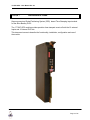
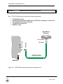
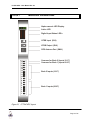
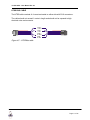
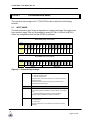
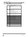
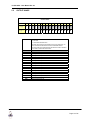
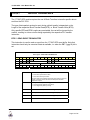
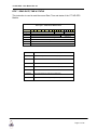
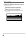
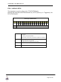
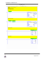
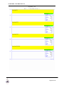
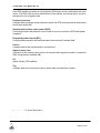
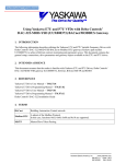
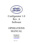
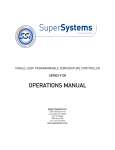
1771HP-GPS
USER MANUAL
Rev 5.0 – Sept 2005
1771HP-GPS - User Manual Rev 5.0
Table of Contents
Chapter 1
Chapter 2
Chapter 3
Chapter 4
Chapter 5
Chapter 6
Chapter 7
Introduction.......................................................................................................3
Module Accessories .........................................................................................4
Module Operation.............................................................................................5
Installing the Module ........................................................................................9
I/O Address Map ............................................................................................12
BLock transfers ..............................................................................................15
Module Status ................................................................................................20
Appendix A PLC Ladder Example .....................................................................................23
Appendix B Specifications .................................................................................................30
Appendix C Glossary .........................................................................................................31
.
Page 2 of 32
1771HP-GPS - User Manual Rev 5.0
CHAPTER 1
INTRODUCTION
Hiprom presents a Global Positioning System (GPS) based Time-Stamping Input module
for the Allen-Bradley PLC5.
The 1771HP-GPS module provides precision time-stamped events of both the 16 external
Inputs and 16 internal PLC bits.
This document serves to describe the functionality, installation, configuration and use of
the module.
.
Page 3 of 32
1771HP-GPS - User Manual Rev 5.0
CHAPTER 2
MODULE ACCESSORIES
Each 1771HP-GPS package includes the following components:
•
•
•
•
•
1771HP-GPS module
5m RG58 patch lead with a SMA male and TNC male connector on either end
3.3V active 50Ω hard mount antenna
1771HP-GPS user manual
HTSB bus cable
Hard-Mount
Antenna
SMA (Male)
SMA (Female)
TNC (Female)
TNC (Male)
RG 58 - 50 Ohm
( Max. Distance 20m )
MASTER
Figure 2.1 : 1771HP-GPS module with antenna and patch-lead
.
Page 4 of 32
1771HP-GPS - User Manual Rev 5.0
MODULE OPERATION
CHAPTER 3
t i mE
ACTIVE
10
00
11
01
12
02
13
03
14
04
15
05
16
06
17
07
Alpha-numeric LED Display
Active LED
Digital Input Status LED’s
HTSB Input (RJ9)
HTSB Output (RJ9)
GPS Antenna Port ( SMA )
18
17
16
15
14
13
12
11
10
9
8
7
6
5
4
3
2
1
Common for Bank 2 (Inputs 10-17)
Common for Bank 1 (Inputs 00-07)
Bank 2 Inputs (10-17)
Bank 1 Inputs (00-07)
Figure 3.1 : 1771HP-GPS Layout
.
Page 5 of 32
1771HP-GPS - User Manual Rev 5.0
The 1771HP-GPS module makes use of the Global Position System (GPS) to provide
accurate time-stamping of PLC and external events.
Events are triggered by a change in either :
One or more of the external 16 digital inputs, (External)
Or one or more bits in the module’s PLC output image. (Internal)
External Inputs
The 16 external inputs are arranged in 2 banks of 8 channels each. These banks are
electrically independent from each other having their own commons. The inputs are
optically isolated and available in either 24Vd.c. or 110Vd.c.
Digital Filtering
In order to prevent unnecessary events from being triggered due to contact bounce etc.
Each external input is digitally filtered. Once an event has triggered on a specific input it is
ignored for the duration of the filter constant. This filter constant is common for all 16
channels and can be configured by the use of a BTW instruction. The default value is
10ms.
Internal Inputs
Events are also triggered by a transition of any one or more of the 16 internal memory bits.
These bits occupy the second word of the module’s PLC output image.
Event Processing
Each event that is triggered is logged to the Event Buffer within the 1771HP-GPS module.
This Event Buffer which can store up to 1000 events operates in a First-In-First-Out mode.
Each entry in the Event Buffer stores the following information pertaining to that specific
event :
Type (External / Internal)
Date
Time
Validity of Time-Stamp
Snapshot of Inputs
Trigger Mask (Cause of the Event)
If there is an unread event in the Event Buffer the 1771HP-GPS module notifies the PLC
by raising a flag (RBT) located in the module’s PLC input image.
The user’s PLC software should monitor this flag, and when ready, execute a Block
Transfer Read (BTR) instruction to read the event.
.
Page 6 of 32
1771HP-GPS - User Manual Rev 5.0
Once the event is successfully transferred to the PLC by means of the BTR instruction it is
removed from the module’s Event Buffer.
Should the Event Buffer still contain an event the RBT flag will remain set and a further
BTR should be executed. Once the Event Buffer is empty the RBT flag will be cleared and
subsequent event BTR’s should not be attempted.
Master / Slave Topology
The precise time-stamping in the module is achieved by synchronisation with the GPS
satellite system.
The 1771HP-GPS-Master module has an on-board GPS receiver providing timesynchronisation information to not only itself, but to other adjacent slaves by means of the
HTSB output port. The -Master module must be connected to an antenna positioned with
an unimpeded view of the sky.
The 1771HP-GPS-Slave module relies on a -Master module in close proximity for time
synchronisation via its HTSB input port. Each -Slave module echos the HTSB signal to its
own HTSB output port to be used by the next -Slave module if required.
Time
Once the module has successfully synchronised or locked onto the satellite system it is
able to render precise time-stamping. Until this state has been achieved the status TNS
flag (Time Not Sync’ed) will be set, and all events generated during this time will be
labelled with the flag signifying a questionable event time-stamp.
On power-up the module defaults to the Universal Time Coordinate (UTC) - defining the
local solar mean time at the Greenwich Meridian (GMT). However, the module’s time-zone
can be configured by means of a Block Transfer Write (BTW) instruction, setting the UTC
offset, that is, the difference between the required local time standard and GMT. Some
examples are listed in the Appendix.
The module’s Time Zone should only be setup on power-up and in the case of daylightsaving changes.
Block Transfers
When a Block Transfer (BT) instruction is issued to the 1771HP-GPS it determines the
nature of the transfer by the size of the BT.
Allowable BT’s and their sizes are as follows :
BTR5
Block Transfer Read of Length 5
- Read / Unload event from Event Buffer
.
Page 7 of 32
1771HP-GPS - User Manual Rev 5.0
BTR7
Block Transfer Read of Length 7
- Read Module’s Status and Time
BTR9
Block Transfer Read of Length 9
- Read Module’s GPS Position and Velocity
BTW3
Block Transfer Write of Length 3
- Configure Module
.
Page 8 of 32
1771HP-GPS - User Manual Rev 5.0
CHAPTER 4
INSTALLING THE MODULE
Install the module
•
Make sure the PLC system power is off.
•
Slot the 1771HP-GPS module into an available slot. The module is designed for
Half-Slot addressing, although it can be used in a Single-Slot configuration if the
module is inserted in an odd slot and the slot to the left of the module is left open.
•
For Master Modules connect a suitable GPS antenna to the antenna port. Make
sure the GPS antenna has an unobstructed view of the sky.
•
For Slave modules connect the HTSB input port to the HTSB output port of an
adjacent Master module or Slave module which in turn is connected a Master.
•
Connect the field cables to the wiring-arm, and slide it onto the module.
•
Apply power to the PLC system
NOTE: Should a longer patch lead be required it is recommended that a GPS signal
booster is used. Contact your local Hiprom distributor for assistance.
Once the module has been power up for the first time, it will search for satellites from a
cold start (i.e no almanac). The module will take approximately 5 minutes to acquire Lock.
Once a complete almanac has been downloaded, the time to achieve fix will be reduced to
around 45 seconds.
MASTER / SLAVE CONFIGURATION
Slave modules are connected to adjacent -Master or other -Slave modules by means of
an HTSB bus-cable.
All 1771HP-GPS modules, both -Master and -Slave, are equipped with an HTSB input and
output port. Take care in ensuring that the HTSB Output port (lower) of the -Master module
is connected to the HTSB Input port (upper) of the next -Slave module. Incorrect
connection of the HTSB bus cable could result in permanent damage to the module.
.
Page 9 of 32
1771HP-GPS - User Manual Rev 5.0
t i mE
t i mE
MASTER
SLAVE
HTSB CABLE
Antenna
t i mE
RG 58
50 ohm
SLAVE
Figure 4.1 : 1746HP-GPS Master / Slave setup
.
Page 10 of 32
1771HP-GPS - User Manual Rev 5.0
HTSB BUS CABLE
The HTSB cable consists of 4 cores terminated on either side with RJ-9 connectors.
The cable should not exceed 1 metre in length and should not be exposed to high
electrical noise environments.
TP+
TPPS+
PSFigure 4.2 : HTSB Bus cable
.
Page 11 of 32
1771HP-GPS - User Manual Rev 5.0
I/O ADDRESS MAP
CHAPTER 5
The input and output image of the 1771HP-GPS module is defined in the following
sections.
5.1
INPUT IMAGE
The data received via input image is dependent on whether the Image Time feature has
been enabled. Image Time can be enabled by setting EIT (Bit 1 of Word 0 of BTW3)
before the configuration block transfer (BTW3) is executed.
Rsv
Rsv
I01
I00
4
3
2
1
0
Rsv
Rsv
I05
5
Rsv
Rsv
I06
Rsv
Rsv
I07
I02
0
Rsv
1
Rsv
2
I03
3
Rsv
4
Rsv
5
I04
6
Rsv
7
Rsv
10
PPS
OVL
11
I11
RBT
12
I12
LOC
I14
ANT
Rsv
I:ggg+1
13
I13
I:ggg
I15
14
Rsv
15
I16
16
TNS
17
I17
Word
I10
INPUT IMAGE ( Image Time Disabled )
Word
17
16
15
14
13
12
11
10
7
6
I:ggg
TNS
Rsv
Rsv
LOC
ANT
RBT
OVL
PPS
Rsv
Rsv
INPUT IMAGE ( Image Time Enabled )
I:ggg+1
Second
Millisecond
Figure 5.1 : Connected Input Image
TNS
Time Not Synchronized
0 = Time Synchronized to GPS
1 = Time NOT Synchronized
The module does not have GPS time and thus is unable to accurately
time-stamp events.
Note that events will continue to be logged to the buffer, but with
possible erroneous time-stamps.
Rsv
LOC
Reserved for Future Use
Satellite Lock
0 = Not tracking sufficient satellites to provide positional / chronological
fixes.
1 = Sufficient satellites being tracked to provide positional fix
Typically, tracking 4 satellites is sufficient to provide lock.
ANT
Antenna OK
0 = Antenna Fault
1 = Antenna OK
An Antenna fault will occur if the antenna is not present or has been
damaged.
.
Page 12 of 32
1771HP-GPS - User Manual Rev 5.0
INPUT IMAGE (CONTINUED)
RBT
Ready for Event Block Transfer Read
0 = No Events in buffer
1 = One or more events in buffer, which are ready for transfer via Block
Transfer.
Note that if an Event Block Transfer Read is attempted when the buffer
is empty, the PLC BTR instruction will fail with Time-out error (-9).
OVL
Buffer Overflow Latch
0 = Buffer has not overflowed.
1 = Buffer has Overflowed.
This Latch will be set when more than 1000 events have been logged to
the buffer but not yet transfered by a Block Transfer.
Once the buffer as Overflowed this bit will remain set until an Overflow
Latch Clear command has been issued.
PPS
BT Rsv
I17
I16
I15
I14
I13
I12
I11
I10
I07
I06
I05
I04
I03
I02
I01
I00
Second
Millisecond
Pulse per Second
This bit transitions from 0 to 1 precisely every second.
The pulse duty cycle is approximately 50%.
Reserved for Block Transfer
Digital Input 17 : Post Digital Filtering
Digital Input 16 : Post Digital Filtering
Digital Input 15 : Post Digital Filtering
Digital Input 14 : Post Digital Filtering
Digital Input 13 : Post Digital Filtering
Digital Input 12 : Post Digital Filtering
Digital Input 11 : Post Digital Filtering
Digital Input 10 : Post Digital Filtering
Digital Input 07 : Post Digital Filtering
Digital Input 06 : Post Digital Filtering
Digital Input 05 : Post Digital Filtering
Digital Input 04 : Post Digital Filtering
Digital Input 03 : Post Digital Filtering
Digital Input 02 : Post Digital Filtering
Digital Input 01 : Post Digital Filtering
Digital Input 00 : Post Digital Filtering
Real-time Seconds. (0-59)
Real-time milliseconds. (0-999)
.
Page 13 of 32
1771HP-GPS - User Manual Rev 5.0
OUTPUT IMAGE
12
11
10
7
6
5
4
3
2
1
0
Rsv
Rsv
Rsv
Rsv
Rsv
Rsv
Rsv
Rsv
Rsv
Rsv
Rsv
Rsv
Rsv
Rsv
M14
M13
M12
M11
M10
M07
M06
M05
M04
M03
M02
M01
M00
17
16
OLC
13
M15
O:ggg+1
14
Rsv
O:ggg
15
M16
Word
OLC
OUTPUT IMAGE
M17
5.2
Buffer Overflow Latch Clear Command
0 = No effect.
1 = Clear Buffer Overflow Latch
The latch will continuously be cleared if the OLC bit remains set. It is
thus recommended that this bit be set and immediatlel cleared.
Rsv
BT Rsv
M17
M16
M15
M14
M13
M12
M11
M10
M07
M06
M05
M04
M03
M02
M01
M00
Once the buffer as Overflowed this bit will remain set until an Overflow
Latch Clear command has been issued.
Reserved for Future Use
Reserved for Block Transfer
Memory Event Output 17
Memory Event Output 16
Memory Event Output 15
Memory Event Output 14
Memory Event Output 13
Memory Event Output 12
Memory Event Output 11
Memory Event Output 10
Memory Event Output 07
Memory Event Output 06
Memory Event Output 05
Memory Event Output 04
Memory Event Output 03
Memory Event Output 02
Memory Event Output 01
Memory Event Output 00
.
Page 14 of 32
1771HP-GPS - User Manual Rev 5.0
BLOCK TRANSFERS
CHAPTER 6
The 1771HP-GPS module requires the use of Block Transfers to transfer specific data to
and from the PLC CPU.
The type of data packet received or sent during a block transfer is dependant on the
Length of the respective Block Transfer Read (BTR) or Block Transfer Write (BTW).
Only specific BTR and BTW Lengths are permissible, the rest will be ignored by the
module, resulting in a time-out error being reported by the respective PLC transfer
instruction.
BTR 5 : READ EVENT FROM BUFFER
This instruction is used to read an event from the 1771HP-GPS event buffer. Note that
instruction should only be executed if data is available, i.e. when the RBT (I:ggg/12) bit is
set.
BTR Length 5 : READ EVENT FROM BUFFER
Word
15
14
0
ETS
MX
13
12
11
10
9
8
7
6
5
4
EvtMonth
1
2
1
0
EvtDay
EvtHour
2
3
EvtMinute
EvtSecond
EvtMillisecond
3
E17
E16
E15
E14
E13
E12
E11
E10
E07
E06
E05
E04
E03
E02
E01
E00
4
C17
C16
C15
C14
C13
C12
C11
C10
C07
C06
C05
C04
C03
C02
C01
C00
ETS
MX
EvtMonth
Event Time Not Synchronized
0 = Event Time Synchronized to GPS
1 = Event Time NOT Synchronized
The GPS Time synchronization status (TNS) at the time the event was
logged. If this bit is set then the event time-stamp data should be
regarded as suspect.
Memory / External Input Event Trigger
0 = Event triggered by External Input Change
1 = Event triggered by Memory Change
The Month when the respective Event was triggered. (1-12)
EvtDay
The Day when the respective Event was triggered. (1-31)
EvtHour
The Hour when the respective Event was triggered. (0-23)
EvtMinute
The Minute when the respective Event was triggered. (0-59)
.
Page 15 of 32
1771HP-GPS - User Manual Rev 5.0
EvtSecond
EvtMillisecond
E17
E16
E15
E14
E13
E12
E11
E10
E07
E06
E05
E04
E03
E02
E01
E00
C17
C16
C15
C14
C13
C12
C11
C10
C07
C06
C05
C04
C03
C02
C01
C00
The Second when the respective Event was triggered. (0-59)
The Millisecond when the respective Event was triggered. (0-999)
Memory / External Input 17, when Event was triggered
Memory / External Input 16, when Event was triggered
Memory / External Input 15, when Event was triggered
Memory / External Input 14, when Event was triggered
Memory / External Input 13, when Event was triggered
Memory / External Input 12, when Event was triggered
Memory / External Input 11, when Event was triggered
Memory / External Input 10, when Event was triggered
Memory / External Input 07, when Event was triggered
Memory / External Input 06, when Event was triggered
Memory / External Input 05, when Event was triggered
Memory / External Input 04, when Event was triggered
Memory / External Input 03, when Event was triggered
Memory / External Input 02, when Event was triggered
Memory / External Input 01, when Event was triggered
Memory / External Input 00, when Event was triggered
Set if Memory / External Input 17, changed
Set if Memory / External Input 16, changed
Set if Memory / External Input 15, changed
Set if Memory / External Input 14, changed
Set if Memory / External Input 13, changed
Set if Memory / External Input 12, changed
Set if Memory / External Input 11, changed
Set if Memory / External Input 10, changed
Set if Memory / External Input 07, changed
Set if Memory / External Input 06, changed
Set if Memory / External Input 05, changed
Set if Memory / External Input 04, changed
Set if Memory / External Input 03, changed
Set if Memory / External Input 02, changed
Set if Memory / External Input 01, changed
Set if Memory / External Input 00, changed
.
Page 16 of 32
1771HP-GPS - User Manual Rev 5.0
BTR 7 : READ DATE, TIME & STATUS
This instruction is used to read the current Date, Time and status of the 1771HP-GPS
Module.
BTR Length 7 : READ DATE, TIME & STATUS
Word
15
0
1
14
13
12
11
10
9
8
CurYear
7
6
5
CurMonth
CurHour
2
3
2
1
0
CurDay
CurMinute
CurSecond
3
BufferLength
4
InputFilter
5
TimeZone
6
Reserved
CurMonth
4
The current Month at time of Block Transfer. (1-12)
CurDay
The current Day at time of Block Transfer. (1-31)
CurHour
The current Hour at time of Block Transfer. (0-23)
CurMinute
The current Minute at time of Block Transfer. (0-59)
CurSecond
The current Second at time of Block Transfer. (0-59)
BufferLength
The number of events resident in the module buffer.
InputFilter
The current Digital Input Filter time in milliseconds.
TimeZone
The current Time-zone configuration. (-12 to 12)
.
Page 17 of 32
1771HP-GPS - User Manual Rev 5.0
BTR 9 : GPS POSITION & VELOCITY
This instruction is used to read the current GPS position and velocity. Both position and
velocity results are referenced to the WGS84 Earth-Centred-Earth-Fixed co-ordinate
system which is defined as follows:
•
The X-axis is defined as the vector with origin at the earth’s centre and passing
through the intersection of the equator and the Greenwhich meridian.
•
The Y-axis is defined as the vector with origin at the earth’s centre and passing
through the equator 90 degrees east of the Greenwhich meridian.
•
The Z-axis is defined as the vector with origin at the earth’s centre and passing
through the North pole.
BTR Length 9 : GPS POSITION & VELOCITY
Word
15
14
13
12
11
10
9
8
7
6
5
0
ECEF X - Position (meters x 1)
1
ECEF X - Position (meters / 10,000)
2
ECEF Y - Position (meters x 1)
3
ECEF Y - Position (meters / 10,000)
4
ECEF Z - Position (meters x 1)
5
ECEF Z - Position (meters / 10,000)
6
ECEF X - Velocity (m/s x 10)
7
ECEF Y - Velocity (m/s x 10)
8
ECEF Z - Velocity (m/s x 10)
4
3
2
1
0
.
Page 18 of 32
1771HP-GPS - User Manual Rev 5.0
BTW 3 : MODULE SETUP
This instruction is used to configure the 1771HP-GPS Module.
Normally this instruction should be executed only on PLC power-up, i.e. Triggered by the
PLC’s First Scan bit.
Rsv
Rsv
Rsv
Rsv
Rsv
Rsv
7
6
5
4
3
2
1
0
CBF
0
8
EIT
9
Rsv
10
Rsv
11
Rsv
12
Rsv
13
Rsv
14
Rsv
15
Rsv
Word
Rsv
BTW Length 3 : MODULE SETUP
1
InputFilter
2
TimeZone
CBF
Clear Buffer
0 = No effect.
1 = Clear ALL events from the Buffer.
The buffer will be cleared each time the BTW is triggered if the CBF bit is
set.
EIT
Enable Image Time
0= Display Input Status on input image
1= Display Seconds and Milliseconds on input image
InputFilter
Configures the Digital Input Filter time in milliseconds.
TimeZone
Configures the Time-zone configuration. (-12 to 12)
.
Page 19 of 32
1771HP-GPS - User Manual Rev 5.0
MODULE STATUS
CHAPTER 7
The current status of the module may be ascertained by either reading the status words
via the PLC5 backplane or by monitoring the alpha-numeric Status Display.
STATUS DISPLAY
TmOk
Time Synchronization Ok
The module has successfully time synchronised with the GPS satellite
system and has accurate time.
Tm??
Time Synchronization Failure
The module has lost time synchronisation with the GPS satellite system
and cannot maintain accurate time.
Tm?x
Time Synchronization Failure
The module has lost time synchronisation with the GPS satellite system
and cannot maintain accurate time.
Where x denotes a time error code (0-9)
IEvt
External Input Event Triggered
A change in the status of one or more of the External Inputs has
generated an event.
MEvt
Memory Event Triggered
A change in the status of one or more of the Memory Output Image bits
has generated an event.
Empt
Full
Event Buffer Empty
There are zero events in the Event Buffer.
Event Buffer Full
There are 1000 events in the Event Buffer, rendering it unavailable for
event logging.
OvFl
Event Buffer Overflow
An event was generated but could not be logged as the Event Buffer was
already full.
Clr
Event Buffer Overflow Latch Cleared
The Event Buffer Overflow Latch has been cleared by the PLC.
This is achieved by momentarily setting the OLC bit
Purg
Event Buffer Purged
All events in the Event Buffer have been deleted.
This is achieved by setting the CBF bit followed by a BTW3.
EPro
Event Processor Started
The Event Processor has started and is ready to process memory events.
This typically occurs 3 seconds after power or changing to Run mode.
Note that External Input Events are immediately available on Power-up of
the module, and remain active when the PLC CPU enters program mode.
.
Page 20 of 32
1771HP-GPS - User Manual Rev 5.0
Prog
PLC entering PROGRAM mode
The PLC CPU is entering program mode or is powering-down.
Run
PLC entering RUN mode
The PLC CPU is entering run mode or is powering-up.
RmEr
Internal Memory Failure
RAM check has failed. Check PLC power supply. Contact supplier.
BTR5
Successful BTR5 request
The module has successfully processed a Block Transfer Read (Length 5)
Request from the PLC CPU.
The data returned will contain the next event from the Event Buffer.
BTR7
Successful BTR7 request
The module has successfully processed a Block Transfer Read (Length 7)
Request from the PLC CPU.
The data returned will contain Date, Time and module Status information.
BTW3
Successful BTW3 transaction
The module has successfully processed data sent from the PLC CPU via
a Block Transfer Write (Length 3) .
Although this indicated that configuration data has been sent to the
1771HP-GPS module by the PLC it is recommended that the configuration
be read back by means of a BTR7 to confirm.
AntO
AntX
GPS Antenna Open-circuit
Indicates the Antenna is not connected or damaged.
GPS Antenna Short-circuit
Indicates the Antenna patch-lead is shorted or damaged or the Antenna is
damaged.
Sky
No Sky Available
Indicates the absence of any satellite signals.
This usually occurs when the Antenna is placed indoors, or during powerup before Lock is achieved.
Srch
Satellite Search
Module is attempting to acquire satellites
Cold
Cold Initialisation Required
Indicates that the module is devoid of internal satellite information.
Time
Satellite Time Synchronisation in Progress
Indicates that the module is receiving satellite signals but has not yet been
able to synchronise to GPS time.
Lock
Satellite Lock
Indicates that sufficient satellites are being tracked to provide position
fixing.
PDOP
Position Dilution of Precision Warning
Position Dilution of Precision occurs when although there are sufficient
satellites in lock, 2 or more of them appear to occupy similar positions in
the sky and thus the number of effective satellites is decreased.
.
Page 21 of 32
1771HP-GPS - User Manual Rev 5.0
Trk1
Tracking only 1 Satellite
Trk2
Tracking only 2 Satellites
Trk3
Tracking only 3 Satellites
SBad
Current Satellite is Bad
The satellite signal currently being acquired is suspect or unusable.
.
Page 22 of 32
1771HP-GPS - User Manual Rev 5.0
APPENDIX A
A.1
•
•
•
PLC LADDER EXAMPLE
LADDER EXAMPLE 1
The module is configured on power-up
As an event is logged by the module it is read
The event Date/Time data is extracted
.
Page 23 of 32
1771HP-GPS - User Manual Rev 5.0
.
Page 24 of 32
1771HP-GPS - User Manual Rev 5.0
.
Page 25 of 32
1771HP-GPS - User Manual Rev 5.0
A.2
•
•
•
LADDER EXAMPLE 2
The module is configured on power-up
Real-Time data is read from the module
The PLC’s Date/Time registers are synchronized to the module.
.
Page 26 of 32
1771HP-GPS - User Manual Rev 5.0
.
Page 27 of 32
1771HP-GPS - User Manual Rev 5.0
.
Page 28 of 32
1771HP-GPS - User Manual Rev 5.0
.
Page 29 of 32
1771HP-GPS - User Manual Rev 5.0
APPENDIX B
SPECIFICATIONS
Parameter
Specification
General
Module Location
Backplane Current
RPI
General
Accuracy Horizontal
Altitude
Velocity
Time
Hot Start
Warm Start
Cold Start
Antenna Connector
Frequency Range
Polarization
Output Impedance
VSWR
Axial Ratio
Gain
Out of Band Rejection
Azimuth Coverage
Elevation Coverage
Coax Type
Impedance
Any Slot
Electrical
515mA @ 5.1V
3mA @ 24V
Schedules Connection Paramters
0.2ms to 750ms
GPS Receiver Specification
L1 frequency (1575.42 MHz), C/A code (Standard
Positioning Service), 8-channel, continuous tracking
receiver,
32 correlators
<6 meters (50%), <9 meters (90%)
<11 meters (50%), <18 meters (90%)
0.06 m/sec
±95 ns or 1 RPI
<14 sec. (50%), <18 sec. (90%)
<38 sec. (50%), <45 sec. (90%)
<90 sec. (50%), <170 sec. (90%)
Antenna
SMA female connector
1575.42 MHz ± 1.023 MHz
Right-hand circular polarization (RHCP)
50Ω
2.0 maximum
90°: 4.0 dB maximum; 10°: 6 dB maximum
35 dB ± 3 Db
fo: 1575.42 MHz
fo ± 20 MHz : 7dB min
fo ± 30 MHz : 12dB min
fo ± 40 MHz : 20dB min
fo ± 100 MHz : 100dB min
360° (omni-directional)
0° to 90° elevation (hemispherical)
Antenna Patch Lead
RG-58
50Ω
.
Page 30 of 32
1771HP-GPS - User Manual Rev 5.0
APPENDIX C
GLOSSARY
Communications format
Format that defines the type of information transferred between an I/O module and its
owner controller. This format also defines the tags created for each /O module
Coordinated System Time (CST)
Timer value which is kept synchronized for all modules within a single ControlBus chassis.
The CST is a 64 bit number with µs resolution.
Coordinated System Time (CST)
Download
The process of transferring the contents of a project on the workstation into the controller
Earth-Centered-Earth-Fixed (ECEF) coordinates
Cartesian coordinate system where the X direction is the intersection of the prime meridian
(Greenwich) with the equator. The vectors rotate with the earth. Z is the direction of
the spin axis, with positive through the north pole.
GPS (Global Positioning System)
A constellation of 24 radio navigation (not communication) satellites which transmit
signals used (by GPS receivers) to determine precise location (position, velocity, and time)
solutions. GPS signals are available world-wide, 24 hours a day, in all weather conditions.
This system also includes 5 monitor ground stations, 1 master control ground station, and
3 upload ground stations.
GPS Antenna
An antenna designed to receive GPS radio navigation signals. These antennas typically
comprise a Low Noise Amplifier (LNA) and are known as active, and thus require DC
power.
GPS Processor
An electronic device that interprets the GPS radio navigation signals (received by a GPS
antenna) and determines a location solution.
GPS Receiver
The combination of a GPS antenna and a GPS processor.
Owner controller
The controller that creates and stores the primary configuration and communication
connection to a module
PDOP Position Dilution of Precision.
PDOP is a unitless figure of merit that describes how an uncertainty in pseudo-range
affects position solutions.
PRN Pseudo-random noise.
.
Page 31 of 32
1771HP-GPS - User Manual Rev 5.0
Each GPS satellite generates its own distinctive PRN code, which is modulated onto each
carrier. The PRN code serves as identification of the satellite, as a timing signal, and as a
subcarrier for the navigation data.
Producer/consumer
Intelligent data exchange system devices in which the GPS module produces data without
having been polled first.
Removal and insertion under power (RIUP)
ControlLogix feature that allows a user to install or remove a module or RTB while power
is applied.
Requested packet interval (RPI)
A configurable parameter which defines when the module will multicast data
Service
A system feature that is performed on user demand
Signal to noise ratio
A measure of the relative power levels of a communication signal and noise on a data line.
SNR is expressed in decibels (dB).
SV
Space Vehicle (GPS satellite).
Tag
A named area of the controller’s memory where data is stored like a variable
(………………./// end of document )
.
Page 32 of 32