1
MC68000 To Bluetooth
ire
Abstract
dsh
This report investigates on the functionality of MC68000 microprocessor flight
board as a medium of system control. The system will able to generate a wireless
connection environment for data transferring, with the use of Bluewave RS232 PCB DCE
Terminal evaluation kit with Bluetooth utility, and thus to interface with a host computer
for
for communication purpose.
In general, this report discusses the following areas: System overview.
2.
Details of RS232 connections and its application.
3.
A deep research on the use of Bluetooth technology and their specification.
4.
System specifications, system design and coding for the powerful MC68000
fH
ert
1.
microprocessor by using C language.
5.
Implementation and analysis of the overall results.
yo
This report also contains the information and guideline for future development of the
project. Though the original objective of producing a proof of concept demonstrator was
not finished due to the complexity and limited time, the report goes on to outline further
Un
ive
rsit
work involving the device for extension at a later date.
1
MC68000 To Bluetooth
ire
Acknowledgement
dsh
I would like to take this opportunity to express my deepest appreciation and
respect to Mr. David Meads who is my principle supervisor, for monitoring my work and
maintaining my consistency with my project. I deeply appreciate for his patient, concern
and advice. Without his excellent and experienced leading, this project would not have
for
come to this completion.
I would also like to extend my special thanks to Ian Munro, which leads me
ert
frequently in the programming, especially to overcome all the difficulties patiently during
the coding process.
fH
I would also like to thanks to Tony Crook and Stephen Passmore who is the
project lab assistant for guiding me on the process of implementation
Finally and most important, I would like to express my greatest respect and
Un
ive
rsit
degree programme.
yo
gratitude to my parents, for their patient and continuous support in throughout the whole
2
MC68000 To Bluetooth
ire
Content
Table Of Contents
1
dsh
Abstract
Acknowledgement
Contents
Glossary of Common Terms & Abbreviations
for
Table of Figures
Table of Tables
Project objective.
1.2
Project Development.
1.3
Report Scope
1.4
Report Layout
System Outline
2.1
Overview
2.2
System Design
2.3
System Hardware
2.3.1
2.3.2
2.3.3
6
7
7
8
8
9
1
10
12
12
12
12
13
Bluetooth Layer
14
RS-232
15
rsit
MC68000 Microprocessor
16
3.1
Overview
16
3.2
Brief Introduction on MC68000 Microprocessor
16
3.3
Introducing MC68000 Flight-68K MKII Board
16
3.3.1
19
3.3.2
3.4
4.
3
Processing Unit
MC68230 peripheral Interface/ Timer circuit (PI/ T) Operation
Un
ive
3.
ert
1.1
fH
2.
Introduction
yo
1.
2
MC68681 Dual Asynchronous Receiver/Transmitter circuit Operation 19
Introducing the Flight Electronics Multi Application Board
20
Introducing New Technology
22
4.1
Overview
22
4.2
Bluetooth Technology
22
4.2.1
Bluetooth Specification
22
4.2.2
Radio Frequency Communication
23
4.2.3
Power Factor of Bluetooth Technology
23
3
MC68000 To Bluetooth
Introducing The Bluetooth Developer's Kit for Windows
25
4.3.2
Introducing the BlueWave RS232 DTE Terminal
27
4.3.3
Introducing The BlueWave Industrial Wireless Cable
5.2
RS-232 Specifications
5.3
Features
5.4
Signal and Connectors.
5.5
Data Format
5.5.1
Binary Data
5.5.2
Text data
for
Overview
ert
5.1
Formats of RS-232 link
Synchronous Format
5.6.2
Asynchronous Format
Prevent Missing Data
fH
5.6.1
32
32
32
33
33
34
34
34
35
35
36
36
Handshaking
5.7.2
Buffers
5.7.3
Interrupts and Polling
5.7.4
Acknowledgement
38
5.7.5
Error-checking
38
37
37
37
Project Development
40
6.1
Overview
40
6.2
Project Design
40
6.3
Hardware Development
43
6.4
Software Development
44
6.4.1
45
Programming on MC68681
Un
ive
7.
29
5.7.1
yo
5.7
ire
4.3.1
RS-232
5.6
6.
25
rsit
5.
Bluetooth Hardware.
dsh
4.3
6.4.2
Programming on MC68230
47
6.4.3
Software setting for BlueWave Industrial Wireless Cable
50
6.4.4
Summary of Project Development
50
Test Plan and Future Development
51
7.1
Overview
51
7.2
Test plan
51
7.3
Future Developments
52
7.3.1
52
Setting offset value for registers
4
MC68000 To Bluetooth
Upgrade Original Operations
52
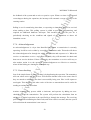
Project Management
8.1
Overview
8.2
Time Management
8.3
Task Management
54
Conclusion
9.1
Report Overview
9.2
Summary
52
ire
7.3.3
dsh
9.
Increase RAM for MC68000 Flight-68K MKII Board
for
8.
7.3.2
References
ert
Bibliography
Appendix A
Appendix B
Un
ive
rsit
yo
fH
Appendix C
5
54
54
55
57
57
58
59
64
65
66
67
MC68000 To Bluetooth
ire
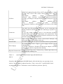
Glossary of Common Terms & Abbreviations.
=
Personal Computer
Hz
=
Hertz, a measurement of frequency
DUART
=
Dual Universal Asynchronous Receiver/ Transmitter
UART
=
Universal Asynchronous Receiver/ Transmitter
R/ W
=
Read/ Write
Bit
=
The smallest unit of a data, either 1 or 0.
Byte
=
unit measurement of data, which from by 8 bits.
ASCII
=
American Standard for Information Exchange
ANSI
=
American National Standards Institute
USB
=
Universal Serial Bus
RS
=
Recommended Standard
V
=
Volt, unit measurement of voltage.
LED
=
Light Emitted Diode
CD
=
Compact Disk
API
=
Application Program for Interfacing
bps
=
Bytes per second
spp
=
serial port profile
RAM
=
Random Access Memory
ROM
=
CMOS
=
PI/ T
=
I/ O
=
rsit
yo
fH
ert
for
dsh
PC
Read Only Memory
Complementary Metal-Oxide Semiconductor
Peripheral Interface/ Timer circuit
Un
ive
Input/ Output
6
MC68000 To Bluetooth
ire
Table of Figures
System Outline ( Simplified)
Figure 2.3.1
MC68000 Flight-68K MKII Board and Multi Application Board
Figure 2.3.2
BlueWave Industrial Wireless Cable
Figure 3.3
MC68000 Flight-68K MKII Board
Figure 3.4.1
Flight Electronics Multi Application Board
Figure 3.4.2
Switch & Lamp Unit
Figure 4.2.2
Master and Slave Role in a piconet.
Figure 4.2.3
Relative Responsiveness versus Power Consumption.
Figure 4.3.1
TDK Bluetooth USB Adaptor.
Figure 4.3.2
BlueWave RS232 DTE Terminal
Figure 4.3.3
BlueWave Industrial Wireless Cable
Figure 5.6.1
Synchronous Transmission
Figure 5.6.2
Asynchronous Transmission
Figure 6.2.1
System Block Diagram
Figure 6.2.2
Interfacing Between Hardware
Figure 6.3
Pin Converter
Figure 6.4
Flow Chart of Software Development
Figure 7.2
Test Plan
rsit
yo
fH
ert
for
dsh
Figure 2.3
Table of Tables
Specifications of MC68000 Flight-68K MKII Board
Table 4.3.2
Specification of BlueWave RS232 DTE Terminal.
Un
ive
Table 3.3
Table 4.3.3(a) LED status of BlueWave Industrial Wireless Cable
Table 4.3.3(b) Specification of BlueWave Industrial Wireless Cable.
Table 4.3.3(C) Original configurations of BlueWave Industrial Wireless Cable.
Table 5.2
RS-232 Specification.
Table 5.4
RS-232 Pins Location
7
MC68000 To Bluetooth
Introduction
ire
1.
World technology today has been highly demand and improved since the recent years.
dsh
People are hunger for appliances, which are more user friendly and high convenient in
supervision and multi purpose. In order for these aims to be satisfied, microprocessor and
microcontroller has upgrade constantly to maintain its excellent performance in the
related industries. Microprocessors are famous with its special industry standard for
for
industrial control and multi-user computer systems, and even to all other embedded
systems and devices.
ert
The purpose of this document is to follow the design and development of a system
to interface with Bluetooth hardware by using a MC68000 Flight-68K MKII Board.
Since the technical solution at this stage is left for investigation, the report will be
1.1
Project objective.
The objective of this project is to: -
Develop two individual circumstances under the same conditions for two
yo
fH
concentrate on the full progress process of this project.
Bluetooth adaptors to transfer and receive data to each other and show the data
on the Hyper Terminal screen under the control of Motorola MC68000
rsit
microprocessor.
Create a software environment to interlink between the hardware and to design
the protocol.
Develop software to control the application board to work as light indicator when
Un
ive
transmission is taking part.
8
MC68000 To Bluetooth
Project Development.
ire
1.2
Due to the size, complexity and limited time scale involved, the overall design of this
dsh
project will be separate into particular part for advanced research. The whole design
procedure will be concentrate on the software basis as it required less of hardware
development. The following methods are used to develop the system: -
for
Information Gathering - A background research on the required information and
hardware, including the relationship between RS-232 and MC68000 flight-board, and the
functionality of Bluetooth.
ert
Physical Design – Research on the overall system design according to the required of the
fH
project objective.
Software Design – The coding procedure that will create a control system for the project,
and it will be separate into several parts according to its own task: -
Flight-board.
yo
1. Interface of the Bluewave RS-232 wireless cable hardware to the MC68000
2. Communicate with the COM2 port of PC and interface with the Hyper Terminal
3. Interface with the application board, which act as the process light indicator.
Un
ive
rsit
4. Transfer of bytes.
9
MC68000 To Bluetooth
Report Scope
ire
1.3
The major practice of this report is to investigate and study on MC68000 flight-board in
dsh
interfacing with a Bluetooth hardware and thus to generate a communication between
PCs. It will give an express idea to the reader and anyone to following up these advanced
technologies in the future.
Report Layout
Chapter 1
for
1.4
Introduction
This chapter give an acknowledgement to the reader about the aim and
ert
objective of this project, it explain the details about this whole report. This
chapter will end with report organization.
System Outline
fH
Chapter 2
This chapter will give a straightforward overview on the overall project
plan by guiding readers to the major system block diagrams that occupied
Chapter 3
yo
in the design method.
MC68000 Microprocessor
In this chapter, MC68000 microprocessor and MC68000 Flight-68K MKII
rsit
Board will be introduced to the reader regarding to its specifications,
major functions and applications. It will also give a basic idea on the Multi
Application Board of MC68000 Flight-68K MKII Board and the
Un
ive
applications of the major internal processor: - MC68230 and MC68681.
Chapter 4
Introducing New Technology
A concise introduces of Bluetooth technology and its application will be
described in this chapter. Special attention will be paid to the ability of
Bluetooth technology in order to help the user to understand about the
practical of this project.
10
MC68000 To Bluetooth
RS-232
ire
Chapter 5
It is the aim of this chapter to give an understanding to the RS-232 link by
looking at its details. RS-232 is the most frequently used link in this
dsh
chapter. Understand the concept of RS-232 will help to penalize the whole
project.
Project Development
for
Chapter 6
This chapter is the main and most important part through out the whole
document. It will describe on the whole process of project developing,
Chapter 7
ert
including the main system design, flow chart and software development.
Test Plan And Future Development
fH
This chapter will introduce the appropriate expansion and ideas for the
future work of this project. It will deal with other features of the project
that has been recommended, by have not been develop.
Project Management
yo
Chapter 8
This chapter introduced the project management process through out the
whole period including the time management and the scheduling task to be
Chapter 9
rsit
complete.
Conclusion
This chapter aim to give a conclusion and summary on the whole
Un
ive
documentation of this project. It will ends with a comment on how the
objective and aims are to be achieved.
11
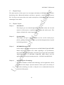
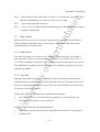
2.
System Outline
2.1
Overview
ire
MC68000 To Bluetooth
dsh
This chapter aim to pioneer the reader to the main system design involved in this project.
It will only give a rough idea to the reader on overall design phases and the use of its
hardware. Full details of the project development will be discussed in chapter 6.
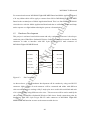
System Design
for
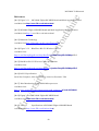
2.2
Basically, the idea of this project is: -
1. To transfer a data and character, which will be typed instantly from PC1, and
ert
transmit to PC2 and show on the screen of monitor with Hyper Terminal
application.
2. To receive data and characters from PC2, and thus to show on the Hyper Terminal
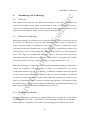
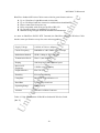
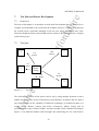
System Hardware
yo
2.3
fH
Screen of PC1.
Bluetooth
Layer
PC 1
Data
Data
rsit
Data
Figure 2.3
PC 2
Data
Data
Processing
Unit
Un
ive
Processing
Unit
Bluetooth
Layer
System Outline ( Simplified)
The overall task of this design required to establish a dual way transmission and it
involved the used of particular hardware, in order to be successful in operation. RS-232links are widely used in this system as it has excellent communication ability in
transmission of data.
12
MC68000 To Bluetooth
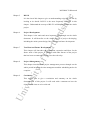
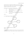
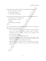
Figure 2.3.1
fH
ert
for
dsh
ire
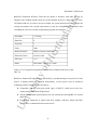
2.3.1 Processing Unit
MC68000 Flight-68K MKII Board and Multi Application Board
yo
[ Ref 1]
The processing unit is the main operating structure in this system. It will form by a
MC68000 Flight-68K MKII Board and an application board. Application software will be
construct according to the system requirement and will be download into the system for
rsit
controlling appliance.
MC68000 will be act as the main processing unit and supervised all the operating process
Un
ive
of this system, including data flow process, capture data from receiver and store into
internal memory and transfer data to the required destination. Data flow process will be
fully control by the application software and thus to organize the scheduling task of
transmission according to the system condition.
Application board is used as the light indicator when the system is in operation. It will
indicate that a data is currently receiving by the system by showing the running light of
LED from right to left, and the reverse order will show the transmitting process. [Ref 2]
13
ire
MC68000 To Bluetooth
Full details on MC68000 Flight-68K MKII Board and its application board will be
dsh
discussed in chapter 3.
2.3.2 Bluetooth Layer
Bluetooth is a special design technology that use for short range communication between
for
computing and communication devices, which enable them to interface wirelessly to each
other. It has major advantages as low power consumption, low cost in developing and
user friendly. For version 1.0 Bluetooth technology, it is able to provide a ten meters
ert
wireless communication, by converting data into radio waves for transmission over a
single air-interface. The main appliances that are currently involved in the development
of Bluetooth technology including mobile phones, notebooks, personal data assistant,
fH
computer and even any external device such as printer, speakerphone and headset.
Bluetooth connection is entirely freedom under all kinds of environment within the
limited range as it operates by using radio waves in 2.4 Giga Hertz frequency spectrums,
Un
ive
rsit
infra-red. [Ref 3]
yo
and there will be no requirements for face to face connection or direct pointing as for
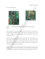
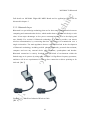
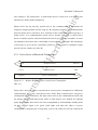
Figure 2.3.2
BlueWave Industrial Wireless Cable
[Ref 4]
14
MC68000 To Bluetooth
ire
The BlueWave Industrial Wireless Cable provides a point-to-point connection between
any two RS-232 devices. It is a plug-and-play device and a Bluetooth wireless link is
established instantly once hey are plug into each RS-232 connector and switched on.
dsh
BlueWave Industrial Wireless Cable unit is fit for both commercial and industries
applications, which required having a more freedom and wireless communication
for
environment. [Ref 5]
Further details of Bluetooth technology and its hardware will be discussed in chapter 4.
ert
2.3.3 RS-232
RS-232 link are the most popular used connections between computer appliances. It is popular
because it is widely available, inexpensive and can be used for longer distance connections by
fH
using wider cables. Most of the computers today have at least one RS-232 communication port,
and some of it even has two. RS-232 used UARTs system, which is able to transmit and receive
data in the same time. In specific explanation, RS-232 is use to interface between the data
Terminal Equipment (DTE) and Data Communications Equipment (DCE) in each
yo
connection to take up a serial data interchange. [Ref 6]
In this project, RS-232 link are used to interface between PC, MC68000 Flight-board and
Un
ive
rsit
BlueWave RS-232 wireless cable. Further details of RS-232 will be discussed in chapter 5.
15
3.
MC68000 Microprocessor
3.1
Overview
ire
MC68000 To Bluetooth
dsh
In the previous chapter, only some major key aspects of MC68000 have been introduced.
This chapter will present a clear and details knowledge to the reader regarding to
MC68000 Flight Board MKII technology, its internal architecture and technical
3.2
for
applications, which will be apply in this project.
Brief Introduction on MC68000 Microprocessor
MC68000 microprocessor is the first achievement of M68000 16/32 bit microprocessor
ert
architecture, which is manufactured by Motorola Company. It has a 16-bit data bus and
24-bit address bus and the full architecture support for 32-bit address and data bus.
Coding on MC68000 is compatible with others M68000 family microprocessors. The
fH
Motorola MC68000 family of microprocessors is now familiar as an industry standard for
industrial organize and multi-user computer systems, which required the speed and power
of an advanced 16/32-bit microprocessor. [Ref 7]
yo
Introducing MC68000 Flight-68K MKII Board
Un
ive
rsit
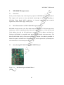
3.3
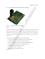
Figure 3.3
MC68000 Flight-68K MKII Board
[Ref 8]
16
MC68000 To Bluetooth
ire
MC68000 Flight-68K MKII Board is a training system that provides an introduction to
the 16/32-bit microprocessor with the most familiar Motorola MC68000 architecture and
functions. This is a very user friendly training system and it has been carefully designed
dsh
to meet the requirement of publics in either commercial or industrial purpose.
MC68000 Flight-68K MKII Board has the capability to upgrade its RAM from 16k bytes
for
to 512 bytes. A 64k byte firmware package is available on this MC68000 Fligh-68K
MKII Board and it provides a mini environment for system development. An expansion
bus is also available for transferring signals to the external drive via a 64 way connector.
ert
The central processing unit of MC68000 Flight-68K MKII Board is a Motorola
MC68000 microprocessor. As same as other M8000 family processor, it has a 16-bit data
fH
bus and a 24-bit address bus, which is able to access a linear address space of 16
megabytes. The whole process of MC68000 Flight-68K MKII Board will be drive by a
10 MHz clock that generated by an internal CMOS oscillator.
yo
Motorola MC68000 microprocessor with 16-bit data bus and 24-bit
address bus
10MHz generated by a CMOS oscillator
CPU
System Clock
Two 27256 32K EPROMs containing the 64K bytes monitor program,
expandable to 128K bytes with use of two 27512 64K EPROMs
Monitor EPROM Address Range: 000000h-00FFFFh (000000h01FFFFh when expanded)
Un
ive
ROM
16K bytes fitted as standard, expandable to 256K bytes RAM
User RAM Address Range: 400400h-403FFFh (400400h-43FFFFh
when expanded)
rsit
RAM
Memory Expansion
Sockets
for
additional
RAM
up
to
256K
On-board RAM Expansion Address Range: 440000h-47FFFFh
17
bytes
ire
MC68000 To Bluetooth
Connectors
Two male 9-way D-type RS232 serial ports, one for connecting with
display terminal or host PC, the other for connecting to a printer or for
general
use
40 way IDC header providing access to the MC68230 Peripheral
Interface/Timer (PI/T) digital input/output and counter/timer lines
64 way male DIN41612 bus expansion connector offering access to all
processor signals of the MC68000 CPU
fH
ert
for
dsh
I/O Ports
MC68230 Peripheral Interface/Timer (PI/T) chip providing 16 digital
I/O lines and a 24-bit wide counter with 5-bit prescaler, with full
interrupt
support
Input/Output
Address
Range:
800001h-800035h
MC68681 Dual Universal Asynchronous Receiver/Transmitter
(DUART) providing two full specification RS232 serial ports with full
interrupt
support
Input/Output
Address
Range:
A00001h-A0001Fh
Three
interrupt
sources
(link
selectable)
Bus Expansion Connector offering access to all 64 lines of the 68000
CPU
Eight external user interrupt vectors, autovectored interrupts, and
eleven trap instructions available to the user
Ten fault switches offer six open circuit and four short to ground faults
Interrupts
Switch Faults
Physical Characteristics
Dimensions: 1575mm wide, 2230mm deep, 160mm high without case
Weight: 1.41lb including case
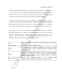
Specifications of MC68000 Flight-68K MKII Board
Un
ive
[Ref 9]
rsit
Table 3.3
yo
Power Supply
The board operates from a single 9V power supply and has a current
consumption
of
700mA
A 110/120V 50/60Hz or 220/240V 50/60Hz power adapter is included
(please specify which is required when ordering)
Generally, MC68000 Flight-68K MKII Board will be divided into two operating circuit,
which is the MC68230 peripheral Interface/ Timer circuit (PI/ T) and MC68681 Dual
Asynchronous Receiver/ Transmitter circuit for different operations. [Ref 10]
18
MC68000 To Bluetooth
ire
3.3.1 MC68230 peripheral Interface/ Timer circuit (PI/ T) Operation
MC68230 peripheral Interface/ Timer circuit is a complex circuit that deals with variety
dsh
of different operations mode required for peripheral interface/ timer system applications.
The features of peripheral interface/ timer circuit including: -
24 individual Input/ output lines, including handshaking
Port model of bit I/O, unidirectional 8 Bit and 16 Bit, and Bidirectional 8 bit and
for
16 bit.
Programmable handshaking option.
24-bit programmable timer mode
ert
5 separate interrupt vectors
There are 23 different register in this circuit and each register are set for different
fH
functions start with the location of $800001.
[Ref 11]
In this project, MC68230 peripheral Interface/ Timer circuit is used as the secondary
yo
controller to conduct the operation of Flight Electronic Multi Application Board for its
Switch & Lamp Unit. These LEDs will indicate the process of data transmission and it
required to have an appropriate setting to the several specific register in order to perform
rsit
the required task.
3.3.2 MC68681 Dual Asynchronous Receiver/Transmitter circuit Operation
Un
ive
This device consists of two separate serial interfaces, which is fully compatible with the
serial port profile (spp) of RS-232 links. One of the serial ports will be connected to the
host computer and another one will be used to interface with any other serial devices.
Features of MC68681 Dual Asynchronous Receiver/Transmitter devices including: Two independent I/O port
Software program baud rate generator
Six parallel inputs
Eight parallel outputs
Separate counter/ timer mode
19
MC68000 To Bluetooth
ire
Again, this device has variety of register to be set and several of the register contain on
the same location n off set value. This register should be set for appropriate values
according to the requirement of user in order to drive the serial port for transmission.
dsh
[Ref 12]
MC68681 Dual Asynchronous Receiver/Transmitter circuit will be used as the primary
for
controller in this project controlling whole data transmission process. Data will be
transfer according to the settings of application program and thus be control by the
register in this serial asynchronous system.
ert
Introducing the Flight Electronics Multi Application Board
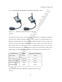
Figure 3.4.1
Flight Electronics Multi Application Board
rsit
[Ref 13]
yo
fH
3.4
The Flight Electronic Multi Application Board is intended to use with a wide range of
original microprocessor training board. It provides the user with a beginning to the
computer control via microprocessor. An eight lever switches facilitate data to be fed
Un
ive
directly to the computer in digital form. This board provides a useful way of simulating
I/O conditions from the user for program testing and debugging ideas. For the connection
figure, Flight Electronic Multi Application Board will be connected to the 40 pins
connector by using a 40 way ribbon cable. Power will be provided with a 240V normal
main adaptor supply, and optionally an 110V is available. [Ref 14]
20
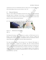
Figure 3.4.2
dsh
ire
MC68000 To Bluetooth
Switch & Lamp Unit
for
[Ref 15]
On Flight Electronic Multi Application Board, Switch & Lamp Unit will be used as the
ert
main function in this project. The switch and lamp unit connects to the 40-way parallel
input/output connector of the FLT-68K and is controlled by the FLT-68K's Parallel
Interface/Timer (PI/T) chip An 8 colored LED will be used as on or off mode, to indicate
fH
the ‘1’ and ‘0’ form of binary code. In this project, these LED will be on and runs from
left to right in binary form, which indicates a data is currently transmitting to the other
terminal. It will be showing that a data is currently receiving from the other terminal
yo
when the LEDs are on and running from right to left. When LEDs are of, it indicates that
Un
ive
rsit
no transmission is in operation.
21
4.
Introducing New Technology
4.1
Overview
ire
MC68000 To Bluetooth
dsh
This chapter aims to introduce the Bluetooth technology to the reader regarding to the
required information, which should be understand in order to bring this project in to
success. Several Bluetooth hardware will be introduced in this chapter as it placed several
4.2
for
important roles through the whole process of project development.
Bluetooth Technology
Bluetooth technology was started to be in research since 1994 and first come into success
ert
in July 1999. It is design by a group of people which form as the result of cooperation of
many companies within an organization. This group of people is leading by a legal
agreement among all the members but it is not a company or a formal body, and the name
fH
of this group of people is acknowledged as “Bluetooth Special Interest Group (Bluetooth
SIG)”. The origin of the Bluetooth SIG were form by Ericsson, Intel Corporation,
International Business Machines Corporation (IBM), Nokia Corporation and Toshiba
yo
Corporation and now, the special group contains over 2000 members. [Ref 16]
Bluetooth technology is a radio frequency based cable replacement technology, and design to
replace the complexity and high costing of cables. It is optimized for low power
rsit
consumption and also low cost in developing. A Bluetooth communication will required
no face-to-face connections between hardware, and even direct pointing as for infra-red
as operate by using radio-wave. In other words, Bluetooth technology is enable to work
Un
ive
under any circumstances and it is entirely freedom under all kinds of environment within
the limited range. A device has to be Bluetooth facilitated (i.e. contain a Bluetooth chip) to be
able to operate a Bluetooth connection with other devices. [Ref 17]
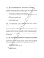
4.2.1 Bluetooth Specification
Bluetooth technology is performed by using the radio waves in 2.4Giga Hz, and it utilizes
a bandwidth between 2.402 – 2.480 Giga Hz. The bandwidth is broken into 79 channels
and is limited to 1 Mega Hertz per channel. The operating speed of Bluetooth is faster
22
MC68000 To Bluetooth
ire
than an Integrated Services Digital Network (ISDN), but slower than an Infra-red.
Bluetooth connections are highly secured as it has consists of various levels of confirmation,
dsh
including pin code admission and up to 128-bit encryption.
Bluetooth devices can be categorized in 3 Efficiency classes:
Class1 :
Highest efficiency with maximum coverage distance up to
100 meters (300 feet).
Class 2 :
Medium efficiency, maximum coverage distance is about 50
for
meters (150 feet).
Class 3 :
Lowest power efficiency with the coverage distance of about 10
ert
meters (30 feet).
[Ref 18]
fH
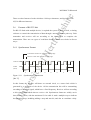
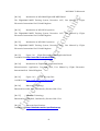
4.2.2 Radio Frequency Communication
yo
Slave
Slave
rsit
Master
Un
ive
Slave
Figure 4.2.2
Master and Slave Role in a piconet.
[Ref 19]
When a Bluetooth link is established, a device will be act as the master and other will be
play apart as the slave mood. A master will have the ability to communicate with 7 active
23
MC68000 To Bluetooth
ire
slave and up to 255 parked slave. A parked slave device is form as it is in standby state
and waits for further acknowledgement.
dsh
Master device do not play any special roles in the communication. It determines the
frequency hopping pattern and the stage for the hopping sequence. All communication
between master device and active slave will form a inter connection called as piconet. A
for
master device in a communication system can be operate as a slave or parked slave
device in another piconet, and interconnection between piconets are acceptable. In some
circumstances the master-slave relationship is not necessary. Although it has advantages
or necessary to give a deices a particular position, it is not critical to establish a single
ert
specific role for each device. [Ref 20]
fH
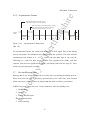
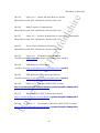
4.2.3 Power Factor of Bluetooth Technology
Highest
Figure 4.2.3
Ssniff/ Ho ld
Park
Power consumption
Lowest
Relative Responsiveness versus Power Consumption.
Un
ive
[Ref 21]
Slowest
rsit
Active
R esponsiveness
yo
Fastest
Figure above show the relative responsiveness versus power consumption in a Bluetooth
communication for a slave and parked slave mode. Both responsiveness and power
consumption will be affected by the major factor such as the communication traffic and
the amount of sniff and hold period. Sniff or hold mood is one method for reducing
power consumption when active slave has accomplished its task and under standby mode
for next interval signal to be given. Sniff mode will allow the reduce of power
consumption by dropping the average duty cycle of the radio but will also reduced the
24
MC68000 To Bluetooth
ire
responsiveness of its own. In hold mode, the device will stop to be in operation in a fixed
interval and waiting for the next cycle to achieve. [ Ref 22]
Bluetooth Hardware.
dsh
4.3
There are numerous Bluetooth hardware promoted in the market due to special demand
and highly improve technology. For this project, several Bluetooth hardware has under
project for wireless communication principles.
for
consideration and analyzed for its specific condition and ability, and thus to locate in this
[Ref 23]
TDK Bluetooth USB Adaptor.
yo
Figure 4.3.1
fH
ert
4.3.1 Introducing The Bluetooth Developer's Kit for Windows
rsit
The Bluetooth Developer’s Kit for Windows are produce by TDK System Ltd. It is
design to assist with PCs, notebooks and laptops for device discovery, bonding and
accessing data in wireless messaging, communication between external device such as
Un
ive
modems and printers, mobile phones and other Bluetooth applications.
The main operating hardware of this developer’s kit is 2 Bluetooth USB adaptor. It
supports Bluetooth 1.1 compliant and compatible with other advanced Bluetooth
interface. It has an intelligently designed APIs (Application Program for Interfacing) for
concise interfaces with other Bluetooth devices and also traced utility for configurable,
real-time monitoring of all stack layers. The application software of this product is
conduct in an application program for interfacing (API) in a CD, which is required to be
installed by the user. [Ref 24]
25
ire
MC68000 To Bluetooth
The Bluetooth Developer's Kit for Windows comes with following components: Software Developer's Kit software.
dsh
Technical Documentation.
2 TDK Bluetooth USB Adaptors.
Windows 98 SE / Me / 2000 (SP 2) / XP
Microsoft Visual C++ 6.0 (SP 5)
USB port
ert
CD-ROM drive for installation
for
System requirement for Bluetooth Developer’s Kit to be operated is describe as below: -
[Ref 25]
fH
After several consideration, the TDK Bluetooth Developer’s Kit was not applied into
implementation due to the following basis: 1.
There is a connection failure between the USB adaptor and MC68000 Flight-
yo
board. USB to serial RS-232 converter required in order to generate a
communication between two interface, and this involve an additional cost and
time to assemble this converter.
Cost of purchasing is over the limited budget of £200.
3.
An account was unable to form due to paper work between University’s account
rsit
2.
department and TDK System Ltd. The account may takes up to 1 months to set up
and it will not be possible to be delivering within 2 months.
Application Program for Interfacing (API) for this hardware was unable to
Un
ive
4.
compatible with the PC compiler to access with the used of MC68000 Flightboard.
26
BlueWave RS232 DTE Terminal
fH
Figure 4.3.2
ert
for
dsh
4.3.2 Introducing the BlueWave RS232 DTE Terminal
ire
MC68000 To Bluetooth
[Ref 26]
yo
BlueWave RS232 DTE Terminal is a serial connection hardware that provides an instant
connection to the master device. A RS-232 connector is required for the master device to
communicate with this device. This hardware requires neither software nor hardware
up to 100m.
rsit
modification to the existing system and will provide a wireless range of communication
Excellent features of BlueWave RS232 DTE Terminal including: -
Un
ive
A plug-and-play device, no additional setting or redesign required.
Connect directly to the RS-232 port of master appliances.
Pins are compatible with regular RS-232 for hardware handshaking.
Able to communicate with up to 7 other Bluetooth device.
Baud rate are adjustable, and up to 115kbps.
A Bluetooth Version 1.1 Compliant.
Compatible with other Bluetooth devices.
[Ref 27]
27
MC68000 To Bluetooth
ire
Specification of BlueWave RS232 DTE Terminal: -
3.3V – 6V (regulated or unregulated power
supply)
Carrier Frequency
2400MHz to 2483.5MHz (USA, Europe)
Modulation Method
GFSK, 1Mbps, 0.5BT Gaussian
Transmission Power
Class 1 (max 20dBm)
Hoping
1600 hops/sec, 1MHz channel space
Receiver IF Frequency
1.5MHz centre frequency
Output Interface
UART (3v), EIA 232 (5V)
Humidity
95% non-condensing
Compliant
Bluetooth™ Specification v1.1
Baud Rate
To 115200baud
Operating Range
100m (328 ft)
Dimensions
40 x 30 x 5 (mm)
[Ref 28]
for
ert
fH
yo
Table 4.3.2
Internal or external via SMA Connector
Specification of BlueWave RS232 DTE Terminal.
rsit
Antenna
dsh
Supply Voltage
This device was also unable to obtain and utilize in this project due to the mistaken order
Un
ive
of product and time arrangement failure from the provider.
28
MC68000 To Bluetooth
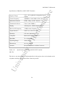
Figure 4.3.3
ert
for
dsh
ire
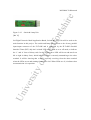
4.3.2 Introducing The BlueWave Industrial Wireless Cable
BlueWave Industrial Wireless Cable
fH
[Ref 29]
The main interfacing system of this project goes to this device, the BlueWave Industrial
Wireless Cable. Similar to BlueWave RS232 DTE Terminal, it is a plug-and-play device.
yo
BlueWave Industrial Wireless Cable consists of a Bluetooth RS-232 master module with
a female connector and another Bluetooth RS-232 slave module with a male connector.
Both of these device are Bluetooth version 1.1 standard and it approve the serial port
profile (spp) and operates as a wireless RS-232 cable. It has built-in LED, which used to
rsit
display status of current Bluetooth connections. The LED status is described as below: -
LED Indication
Mode
Bluetooth Connection
Data
None
Slow flash (1Hz)
Command
None
Quick flash (2Hz)
Command
Active
LED off steady
Data
None
LED on steady
Data
Active
Un
ive
Single flash
Table 4.3.3(a) LED status of BlueWave Industrial Wireless Cable
[Ref 30]
29
MC68000 To Bluetooth
Up to 330m line of sight Bluetooth wireless link
Up to 230.4kbps baud rate connection with hardware handshaking.
Direct connection from power up.
Fully compatible with serial port profile of RS-232.
No external software or installation is required.
Manufacturing strength aluminum attachment and antenna.
dsh
ire
BlueWave Industrial Wireless Cable comes with the great features such as: -
for
As same as BlueWave RS232 DTE Terminal, the BlueWave Industrial Wireless Cable
has the same specification except for some minor upgrading: -
110-240 AC Power Adaptor
Carrier Frequency
2400MHz to 2483.5MHz (USA, Europe)
Modulation Method
GFSK, 1Mbps, 0.5BT Gaussian
Transmission Power
Class 1 (max 20dBm)
Hoping
1600 hops/sec, 1MHz channel space
Receiver IF
Frequency
1.5MHz centre frequency
Output Interface
EIA 232 (5V)
Humidity
95% non-condensing
Compliant
Bluetooth™ Specification v1.1
Operating Range
fH
yo
To 230.4kbps baud rate
100m (328 ft)
External via SMA Connector
Un
ive
Antenna
rsit
Baud Rate
ert
Supply Voltage
Table 4.3.3(b) Specification of BlueWave Industrial Wireless Cable.
[Ref 31]
30
MC68000 To Bluetooth
ire
BlueWave Industrial Wireless Cable has the ability to interface with other devices by
using the slave module and the range are from minimum speed of 1.2kbps baud rate up to
230.4kbps baud rate. In order to be user friendly, the system allowed user to configure the
dsh
settings according to the system requirement by only few straightforward procedure that
excluding the need for external complicating program development.
115.2kbps
Data Bits
8
Stop Bits
1
Parity
None
Bluetooth Mode
Enables instant connection
Bluetooth Name
wireless cable
PIN code
1111
Mode
Data mode. Unit act as a cable.
yo
fH
ert
for
Baud Rate
Table 4.3.3(C) Original configurations of BlueWave Industrial Wireless Cable.
[Ref 32]
rsit
BlueWave Industrial Wireless Cable was finally be purchased and put into practice in this
project. It highly fulfills the required functionality of this project with its advanced
technology and the following special features: -
Un
ive
Compatible with all serial port profile (spp) of RS-232, which used as the key
connection for MC68000 Flight-board.
Able to transfer data asynchronously for any transmission through RS-232 format
and link.
Providing a separation of master and slave module, and thus simple and fully
equipped for communication between two PC.
31
5.
RS-232
5.1
Overview
ire
MC68000 To Bluetooth
dsh
This chapter aim to introduce the reader to the world of RS-232, including its
specification, characteristic and major utility. It will give the reader a further
understanding on the usage of two individual RS-232 port and its connectors in this
5.2
for
project.
RS-232 Specifications
RS-232 (Recommended Standard-232 model) is one of the most common use links for
ert
interfacing between two devices, and with a limit of 50 to 100 feet and it depends on the
peripherals and cable that is used. Another popular use of the RS-232 link is to connect to
an adaptor that converts the interface to another type, such as from RS-232 to USB
fH
(Universal Serial Bus).
The Telecommunications Industry Association (TIA) has distribute the details about RS-
yo
232, including signal functions, pin locations and other specifications, and it has been
upgrade promptly since it was publish in 1960s. A version that was produce by
Electronics Industries Association (EIA) has been taking over and now the latest version
rsit
since 1997 is YIA/ EIA-232F and this interface is compatible with RS-232. [Ref 33]
Format
Un
ive
Interfacing
RS-232
Asynchronous
(EIA/ TIA-232)
serial
Table 5.2
Number
Length
Speed
devices
(maximum,
(maximum,
(maximum
feet)
bits/ sec.)
2
50 - 100
RS-232 Specification.
[Ref 34]
32
of
20k (115k with
some drivers)
MC68000 To Bluetooth
Features
ire
5.3
1. RS-232 is popular. Every PC will have one or more RS-232 adaptor to link to
dsh
other device such as printers, modem, microcontroller or microprocessor, and
even to another PC.
2. Linking system can be 50 to 100 feet long, depends on the peripheral and cable
used.
for
3. It is easy to convert a 5V serial port to an RS-232 link and microprocessor and
microcontroller system.
4. There will only three wires for a 2-way link system. A RS-232 normally consists
ert
of 9 pins, including a ground connector. The cost of cables and large connectors
will be reduced.
Pin
Signal
1
CD
Signal and Connectors.
2
3
4
Description
control
Carrier detect
RD
data
Received data
TD
data
Transmitted data
DTR
control
Data terminal ready
GND
rsit
5
Type
yo
5.4
fH
[Ref 35]
6
DSR
control
Data set ready
7
RTS
control
Request to send
8
CTS
control
Clear to send
9
RI
control
Ring Indicator
Un
ive
Table 5.4
Signal ground
RS-232 Pins Location
[Ref 36]
For RS-232, only pin 2, 3, 4, 5 and 8 will be used in common applications.
Pin 2 - Receive data from the transmitter.
Pin 3 - Transmit data to the receiver.
33
MC68000 To Bluetooth
hardware handshaking to take place, in order to receive data.
Pin 5 - A 0V common ground connection.
ire
Pin 4 - Data terminal ready, which drive a positive 5V from the PC and thus to allow
dsh
Pin 8 - Clear to sent, providing hardware handshaking in the other direction, to indicate
a signal for sending data.
Data Format
for
5.5
Data that will be sent or receive through a transmission can be represent in all kinds of
format, including commands, codes, text message or information. These data will be
ert
encoded as binary or text data form.
5.5.1 Binary Data
fH
The value of the binary are from 0 to 255, which are square numbered of 0 through 7,
with represent of either 1 or 0 multiplied by a power of 2. For example, a byte of 1111
1111 will be translated to value 255, or FF in hexadecimal. In a transmission process, the
significant bit (MSB).
5.5.2 Text data
yo
least-significant bit (LSB) will always be transfer first, and then only follow by the most
rsit
Although binary data is useful in many linking system, the operation still required an
additional format to send message or files that enclose with text. Text data are use for the
purpose of sending data that contain of text. There are several formats of text data which
Un
ive
is being use in the linking system: -
ASCII code (American Standard code for Information Exchange)
This format consists of 128 codes and just required to use seven data bits. The
remaining bit will either be a 0 or a parity bit.
ANSI code (American National Standard Institute)
This format uses 256 codes, and special and inflection characters are represent by
the higher code,
34
ire
MC68000 To Bluetooth
There are other formats of codes which use 16 bits per characters, and it tolerate with
5.6
dsh
65,536 different characters.
Formats of RS-232 link
For RS-232 links with multiple device, it required the system to have a clock, or timing
for
reference to control the transmission of data through a network or share path way. Each
transmitter and receiver will act according to the time signal to complete the
transmission. There are two types of serial data formats, which uses clocks in diverse
ert
ways: -
fH
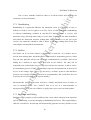
5.6.1 Synchronous Format
Transmitter sends bits on clock's falling edge.
CLOCK
DATA
(61H)
Figure 5.6.1
1
0
0
0
0
BIT 0
1
Synchronous Transmission.
Un
ive
[Ref 37]
1
rsit
BIT 7
0
yo
Receive r reads bits on clock's rising edge.
In this format, the network will share an external clock, or a same clock which is
generated by a particular of the device. All the transmission bits will be transmitting
according to the clock signal, which have a fixed frequency. Receiver will act according
to this signal and decided when to receive a bit. Synchronous format are widely use in
short linking system, with the maximum 15 feet cable. It used a multiple ways to indicate
the operation steps, including adding a stop and start bit, and also to contribute a chip-
35
MC68000 To Bluetooth
Un
ive
rsit
yo
fH
ert
for
dsh
(MSB) first, then only follow by the least significant bit (LSB).
ire
select signals. Many synchronous protocols send data begins with a most significant bit
36
MC68000 To Bluetooth
ire
5.6.2 Asynchronous Format
Receive r detects the falling edge of start
then uses its internal clock to r ead the
following bits near their centers.
Figure 5.6.2
BIT 7
0
1
1
0
Asynchronous Transmission.
[Ref 38]
0
0
0
BIT 0
1
STOP
BIT
ert
START
B IT
for
DATA
(61H)
dsh
Transmitter uses an internal clock
to determine when to send each bit.
fH
For asynchronous format, the system will not include a clock signal. Each of the linking
system will produce an individual clock signal through the operation. The most common
asynchronous link format is 8 – N – 1, which sent each data byte as one start bit,
yo
following by a eight bits data, begin with the least significant bit (LSB), and then
continue with the most significant bit (MSB), and finally ends with one stop bit. There
will be no parity during the operation.
Prevent Missing Data
rsit
5.7
Missing data is one of the unexpected errors that will occur during the linking process.
When more than one task is operating synchronously in the same time, some internal
Un
ive
failure will cause a missing data to be happen and thus lead to a failure performance.
In RS233 network system, there are 5 major methods to solve this linking error: 1. Handshaking
2. Buffers
3. Polling and Interrupts
4. Acknowledgement
5. Error-checking
37
MC68000 To Bluetooth
ire
One or more methods should be taken to avoid the failure and maintain the
consistency of the performance.
dsh
5.7.1 Handshaking
Handshaking is a signal that indicates the transmitter when it is necessary to sent, or
indicates a ready to receive signal to a receiver. There is either a hardware handshaking
for
or software handshaking available in each RS-232 linking system. A receiver will
automatic bring a line high when ready to receive data. In this time, the other transmitter
will follow the instruction and start sending data. Whenever there is a line low in the
ert
receiver, the transmitter should be able to detect it and stop sending data till the line
return high to accomplish the transmission.
fH
5.7.2 Buffers
The buffer can be in either software or hardware, or both also. It is another way to
prevent from missing data, and buffer can be more useful to transmitting process, which
they can store data that will be sent out as the communication is available. Each serial
yo
linking has a built-in 16 bytes buffer that built on the UARTs. The data will be
temporally store in this buffer on receiving process before the software is able to read it.
For transmitting process, UART will automatic supervise the transmission of the byte bit
rsit
by bit, in the arrange order. There is a necessary a software protocol when hardware
protocol is not enough. Software protocols are programmable, and it will allow the user
to specify the size according to the system memory.
Un
ive
Microcontroller and microprocessor will have a smaller and limited size of buffer, or
even no hardware buffer. For a RS-232 link to be use in a microcontroller or
microprocessor system, the user will have to apply other ways to prevent missing data.
5.7.3 Interrupts and Polling
Interrupts can be program to effect and detect the events, which take part in the operation
such as transmitting, receiving, changing of handshaking and errors. This programming is
called as event-driven. An interrupt will automatically generate necessary actions to react
38
MC68000 To Bluetooth
ire
the feedback of the system and to active or passive a port. When ever there is an external
events happen during the operation, the interrupt will automatic execute to jump to the
dsh
exacting routine.
Polling is use for transferring short data, or expecting an immediate data to be received
when sending a data. This polling system is called as procedure programming, and
for
required no additional hardware interrupts. This method will pool the port for a
periodically checking on the condition and signals of the operations to detect all
immediate events.
ert
5.7.4 Acknowledgement
An acknowledgement is a byte that identified the system a transmission is currently
fH
operating. It will be receive either by a receiver or transmitter node. This node will detect
the acknowledgement far through the whole transmission and response to it. When the
receiver or transmitter receive a reply from the node, they will automatic be admit and
thus sent or receive the data. If there is no reply, the transmitter or receiver will retry or
yo
take another action in to the operation. Acknowledgement are effective to networks,
where all the linking are sharing the same path way.
rsit
5.7.5 Error-checking
One of the simple forms of error-checking is by duplicating the operation. The transmitter
will sent a data twice and the receiver will confirm whether both are the same data. If
they are match to each other, the data is successfully being sent. Else it will request to
Un
ive
send again. This duplicate task takes twice of the time to transmit data and is useful for
sending occasional and short data.
Another error-checking process called a checksum, and operates by adding an errorchecking byte to the transmission. The system will perform the calculation from an
arithmetic or logical operation at the specified byte through the message. The receiving
process ends with calculating the final result, and if the result is not same, then the system
will realize that the transmission is not success.
39
ire
MC68000 To Bluetooth
A CRC (cyclic redundancy code) is another error-checking ways by using calculations,
but it required on more complex math and is also more consistent than a checksum.
Un
ive
rsit
yo
fH
ert
for
dsh
[Ref 39]
40
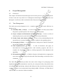
6.
Project Development
6.1
Overview
ire
MC68000 To Bluetooth
dsh
In chapter the system outline has been defined, this chapter goes on to show the actual
physical design and software development of this project. It is the aim of this chapter to
give a clear explanation on every practical task that involved in project progress and how
6.2
for
each task is accomplished.
Project Design
The whole project will be design according to following aims and objectives: Develop two individual circumstances under the same conditions for two
ert
Bluetooth adaptors to transfer and receive data to each other and show the data on
the Hyper Terminal screen under the control of Motorola MC68000
fH
microprocessor.
Create a software environment to interlink between the hardware and to design
the protocol.
Develop software to control the application board to work as light indicator when
yo
transmission is taking part.
In order to achieve these aims and objectives, a logical plan is first conducted to design a
rsit
connection aspect between all hardware. This system design will give a guideline to
Un
ive
interface all devices and thus to communicate with each other.
41
r
fH
ert
fo
Text Editor
yo
Compiler
Serial
RS-232 cable
MC68k
Flight-68K
MKII Board
rsit
PC1
MC68000 To Bluetooth
Text Editor
Y
Serial
RS-232 cable
Y
BlueWave
Industrial
Wireless Cable
BlueWave
Industrial
Wireless Cable
Un
ive
40 way
ribbon cable
Hyper
Terminal
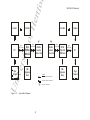
Figure 6.2.1
Compiler
Serial
RS-232 cable
MC68k
Flight-68K
MKII Board
Serial
RS-232 cable
PC1
40 way
ribbon cable
Multi
Application
Board
S ymbol
h ardware connection cable
soft ware internal con nection
Y
System Block Diagram
42
wireless connection
Multi
Application
Board
Hyper
Terminal
ire
MC68000 To Bluetooth
Figure above show the connections that apply in this project. Basically, there are two
same system models to be in operation. PC1 will act as the master module and PC2 will
dsh
be act as slave module. All hardware will be under same condition and installed with
same operation program. An internal software connection will be appearing to interface
between center processing unit with software compiler, text editor and Hyper Terminal
ert
for
operations.
Multi
Application
Board
PC 1
Serial
RS-232 cable
Serial
RS-232 cable
Bluewav e
Industrial wi reless
hardwar e
Y
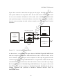
Interfacing Between Hardware
rsit
Figure 6.2.2
yo
24 way
ribbon cable
fH
MC68K Fli ght-68K
MKII Board
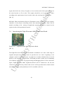
As shown above, a serial links will appear between MC68000 Flight-68K MKII Board
Un
ive
with host computer and BlueWave Industrial Wireless Cable. An RS-232 cable will be
used to interface from COM2 port of host computer to LK2 9-pin D-type RS-232 male
connection on MC68000 Flight-68K MKII Board. An original built-in RS-232 link cable
on the BlueWave Industrial Wireless Cable then will be connect to the LK3 9-pin D-type
RS-232 male connector of MC68000 Flight-68K MKII Board. The purpose of this serial
link is to interface the host computer to MC68000 Flight-68K MKII Board and thus to
generate commands and operation to BlueWave Industrial Wireless Cable for
transmission of data.
43
MC68000 To Bluetooth
ire
For connection between MC68000 Flight-68K MKII Board and Multi Application board,
a 24 way ribbon cable will be apply to connect from LK4 of MC68000 Flight-68K MKII
Board to the terminal port of Multi Application Board. This is to link between MC68681
dsh
circuit device with the Multi Application Board and thus to utilize the switch and lamp
unit to operate as a light indicator during the process of transmission.
Hardware Development
for
6.3
This project is software based achievement and only a minor pin converter is develop to
switch the pins of BlueWave Industrial Wireless Cable slave module from male to female
ert
connector in order to interface with LK3 9-pin D-type RS-232 male connector of
2
TX Data
3
Ground
5
yo
RX Data
fH
MC68000 Flight-68K MKII Board.
RX Data
3
TX Data
5
Ground
7
7
CTS(I/P)
RTS (O/P )
8
8
RTS (O/P)
rsit
CTS(I/P)
Pin Converter
Un
ive
Figure 6.3
2
As shown above, a simple hardware development will be conduct by using two RS-232
connector. Male module of each connector will be connected and solder with different
color according to above settings. Only 5 major pins were used in this serial link and each
of it is identified by using different color wires. This converter will be used to modify the
slave module of BlueWave Industrial Wireless Cable into a female connection point for
interfacing with LK3 9-pin D-type RS-232 male connector of MC68000 Flight-68K
MKII Board and function as same as the master module device.
44
MC68000 To Bluetooth
Software Development
ire
6.4
dsh
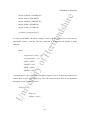
Start
No
for
Job / Task
LE D Off
ert
Yes
Yes
Receive data
fH
LED indi cator runni ng
from left to right
No
Tempo rall y s tor e data into
memory addres s in flight-board
yo
T rans fer t o t he P C and show
on the monitor s creen
LED Off
Yes
rsit
Transfer data
LED indi cator runni ng
from r ight to left
No
Un
ive
Temporally sent d ata to
memory addres s in flight-board
Trans fer th e data from flight-board to
desti nat ion t hrough Blu ewave RS232
LED Off
End
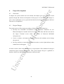
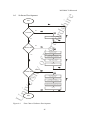
Figure 6.4
Flow Chart of Software Development
45
MC68000 To Bluetooth
design and implement according to the three main function below: -
ire
According to the flow chart above, the software development for this project will be
1. To generate a software environment for MC68681 Dual Asynchronous
dsh
Receiver/Transmitter circuit to operate as a medium of data transmission between
host computer and BlueWave Industrial Wireless Cable.
2. To drive the LEDs on switch and light unit of Multi Application board to work as
for
a data receiving indicator by activating the running light from left to right.
3. To drive the LEDs on switch and light unit of Multi Application board to work as
a data transferring indicator by activating the running light from right to left.
ert
In order to implement this functions into operations, a series of program has been develop
by using C programming language to compile with the original MC68000 programming
fH
method. The overall system will be divided into two major part, which is the controlling
process of data transmission by MC68681 Dual Asynchronous Receiver/Transmitter
device and light indicator by MC68230 peripheral Interface/ Timer device.
yo
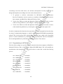
6.4.1 Programming on MC68681
The aim of this coding is to provide a direct connection from host computer to BlueWave
Industrial Wireless Cable via MC68000 Flight-68K MKII Board. This will establish an
process.
rsit
asynchronous data transmission to the system thus to control the overall data flowing
= 0xA00001;
char *MRBPTR
= 0xA00011;
char *CRAPTR
= 0xA00005;
char *CRBPTR
= 0xA00015;
char *OPRPTR
= 0xA0001D;
char *IPCRPTR
= 0xA00009;
char *OPCRPTR
= 0xA0001B;
char *ISRPTR
= 0xA0000B;
char *CSRAPTR
= 0xA00003;
Un
ive
char *MRAPTR
46
MC68000 To Bluetooth
= 0xA00013;
ire
char *CSRBPTR
#define MRA (*MRAPTR)
dsh
#define MRB (*MRBPTR)
#define CRA (*CRAPTR)
#define CRB (*CRBPTR)
for
#define OPR (*OPRPTR)
#define IPCR (*IPCRPTR)
#define OPCR (*OPCRPTR)
#define ISR (*ISRPTR)
ert
#define CSRA (*CSRAPTR)
fH
#define CSRB (*CSRBPTR)
The above commands are program heading, which used to define an register with an
appropriate name and to establish the memory location for each register. This is the most
important steps and it will effect the overall operations of each register by directing it to
yo
the actual memory location. These memory location will have its own interconnection
with original processor and will trigger its individual responsible operation when a
main()
{
rsit
command is given.
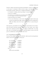
MRA = 211;
Un
ive
MRB = 48;
CRA = 133;
CRB = 133;
OPR = 252;
IPCR = 15;
CSRA = 187;
CSRB = 187;
}
47
MC68000 To Bluetooth
ire
The above coding is the main body instruction for MC68681. It will give an initial value
to each register to command for different internal settings to each dependable memory
location and its operation. With the above command, the MC68681 is set to be: Receiver is enabling .
dsh
Transmitter is enabling, with each providing a 1 bit stop bit length.
Systems are to be asynchronous to each data transmission.
Auto configure to the current transmission status.
for
Input and output port is enabling.
Set to sent each data byte as one start bit, following by a eight bits data, begin
with the least significant bit (LSB), and then continue with the most significant bit
ert
(MSB), and finally ends with one stop bit. There will be no parity during the
fH
operation.
Each register are given different off value to represent a special function in the memory
status and related controlling operations. Offset value for each register can be change
based on the requirement operation of user. It is highly recommend that every single
yo
offset value in its individual register should be examined promptly to ensure a successful
process is established in communication with other devices.
rsit
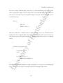
6.4.2 Programming on MC68230
The aims of this coding are to control the MC68230, which control the multi application
board to works as the light indicator in this project.
= 0x80000D;
char *PADDRPTR
= 0x800005;
char *PBCRPTR
= 0x80000F;
char *PBDDRPTR
= 0x800007;
char *PBDRPTR
= 0x800013;
char *PADRPTR
= 0x800011;
Un
ive
char *PACRPTR
#define PACR (*PACRPTR)
48
MC68000 To Bluetooth
ire
#define PADDR (*PADDRPTR)
#define PBCR (*PBCRPTR)
#define PBDDR (*PBDDRPTR)
dsh
#define PBDR (*PBDRPTR)
#define PADR (*PADRPTR)
for
void delay (unsigned char L);
As same as MC68681, the above coding is used to set the register for a name with an
appropriate memory location. The last command is a function that defines a delay
ert
authority.
{
fH
main()
unsigned char count = 255;
unsigned char L = 10;
yo
PARC = 0X80;
PADDR = 0X0;
PBCR = 0X80;
rsit
PBDDR = 0XFF;
Command above will set the Port A data direct register to act as an input port and the Port
B data direct register as an output port. This will control the data flow of the operations
Un
ive
during the system operating process.
while (1)
{
delay (L);
PBDR = count--;
}
49
MC68000 To Bluetooth
ire
The above coding mentioned that, when there is a data transmitting process, the LEDs
will be running from right to left in binary form, where data in PBDR will be decrease
from 128 to 1, then go back to the original looping of 128 again until the function receive
dsh
a command to stop.
while (2)
for
{
delay (L);
PBDR = count++;
ert
}
When the condition is 2 indicate there is a data receiving process, the LEDs should be
fH
running from left to right in binary form where data in PBDR will be increase from 1 to
128, then go back to the original looping of 1 again until the function receive a command
to stop.
yo
}
void delay (unsigned char L)
rsit
{
unsigned char E;
int D;
Un
ive
for (E=0;E<=L;E++)
for (D=0;D<10000;D++);
}
The function interruption indicates a delay and break in every process of running light
system. The greater the value of looping, the fastest the running LEDs will be.
50
MC68000 To Bluetooth
ire
6.4.3 Software setting for BlueWave Industrial Wireless Cable
In order to have a same baud rate as the MC68000 Flight-68K MKII Board, the
dsh
BlueWave Industrial Wireless Cable need to configure its own setting to operate at 9600
baud, no parity, 8 data bits and with a stop bit. The operation steps below shows the
configuration for BlueWave Industrial Wireless Cable: -
1. Connect the BlueWave Industrial Wireless Cable into the COM2 port of the host
for
computer and switch on the device.
2. Open Hyper terminal application and configure it to the original setting of
BlueWave Industrial Wireless Cable- 115200 bps, no parity, 8 data bits and 1 stop
bits.
ert
3. Type “++++” then enter.
4. Type “AT+BWB=3” to set baud rate to 9600 bps.
fH
5. A message will then return to indicate that configuration was been update
successfully.
6.4.4 Summary of Project Development
yo
After all software coding and configuration has been set up, the device will be connected
by using the appropriate cable. Application program will be compile, then debug and run.
A Hyper Terminal screen will be operates under this condition. When user type in an
rsit
character in the HyperTerminal application and it appears on both screen of master and
slave PC, and the LEDs in Multi Application Board are running accordingly, it indicates
Un
ive
that the project was successfully done and the objective of this project is fulfilled.
51
7.
Test Plan and Future Development
7.1
Overview
ire
MC68000 To Bluetooth
dsh
The aim of this chapter is to introduce several detail investigation plan for this project. It
is highly recommended to the reader that the schedule will give a further understand on
the overall project operations although it has not been apply due limited time scale.
Future development plan are also included for the reader to discover and achieve a higher
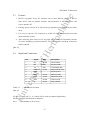
3
ert
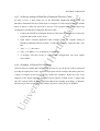
Test plan
10.0
meters
8.0
meters
0.5
meter
PC1
Master
Setting
yo
2
rsit
2.0
meters
1
5.0
meters
4
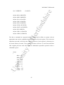
Test Plan
Un
ive
Figure 7.2
5
fH
7.2
for
result in this project.
The final implementation of the system will be test by using multiple locations on slave
module and test for the speed of transferring versus distance. In details, this test plan is
used to investigate on the capability of Bluetooth technology on transferring data over
certain limited distance without face-to-face connections. Master setting will be
positioned at the center of Room LD403, and slave module will be installed according to
Figure 7.2 for different distance and investigate the transferring rate for each location.
52
MC68000 To Bluetooth
ire
First, a fix byte size data will be sent from master PC to slave PC. Data will be set
according to the user and this data will continuous to be transmitted to slave PC until
transmission is complete. These procedures will be repeated again by slave PC to
dsh
transmit the appropriate data back to master PC for all distance. All evaluation will be
scan by using oscillator and details of reading will be record down and form a
for
transferring speed versus distance graph.
Unfortunately, this test plan has not been implement to the actual project system due to
the complexity and limited time, and it will goes for continuation by future undergraduate
7.3
ert
at a later date.
Future Developments
fH
7.3.1 Setting offset value for registers
Setting up the register in each individual circuit is the most important issue in developing
the program operating software. There is an error occur during communication within
two PC in the current operating program. This was cause by a failure offset value among
yo
the registers and it has not been solve due to the complexity and limited time for trouble
shooting. In future, all offset value of register in MC68230 and MC68681 should be
check and upgrade, in order to carry out a successful operations and optimum
rsit
performance.
7.3.2 Increase RAM for MC68000 Flight-68K MKII Board
Un
ive
For future development, the user should expand the RAM to a higher memory status to
allow a more effective and speed up process to operate on MC68000 Flight-68K MKII
Board. By having a higher RAM on the board, the system will be able to generate more
operations for process control system.
7.3.3 Upgrade Original Operations
Original system can be design and upgrade to a higher level of operation system. As it
communication between a master slave module, the system can be upgrade into a high
53
MC68000 To Bluetooth
ire
security communication system. The master PC will act as the main security system and
all users will be request to enter their identification password on the slave PC and sent to
master PC. On the other side, master PC will check all the details of the request user for
dsh
their background and membership through the data base by using the received
identification password and thus to decide whether they are qualified or opposite.
for
In another future planning, master PC can be act as an automatic calculation system for
any system that required high security. In the same manner, user will be request to enter
an amount on the screen, and this figure will be received by the master PC. After
receiving data, master PC will do a line of calculation according to the amount that has
ert
been enter and thus to generate a request computation. When final result is being
generate, the user of master PC will then type the result on the screen and sent it back and
Un
ive
rsit
yo
fH
show on the screen of slave PC.
54
8.
Project Management
8.1
Overview
ire
MC68000 To Bluetooth
dsh
This chapter will define the detail through out the whole process of project management.
It aims to show the steps and level of management and changes or upgrading that occur
during the overall route, and in conclusion ends with project documentation.
Time Management
for
8.2
The whole process development is to be complete within 181 days and it falls into six
distinct levels: -
ert
Feasibility Study (12 days) - to set the aim and objective for this project, and to
blueprint a systematic plan to drive the process of development.
Project Analysis and Information Gathering (38 days) – involve in effort of
fH
analyzing the project system and collecting the necessary information
Further Study and Analysis (40 days) – to have a deep understanding into the
internal factors of project hardware and thus to plan the corresponding system.
Prototyping (54 days) – to construct software coding and to finalize all analysis
yo
on necessary hardware development.
Final Implementation (32 days) – to unite all hardware and apply an
interconnection between al hardware with assembly program, and also to
upgrading.
rsit
complete the developing process by making appropriate final adjustment and
Documentation (60 days) – to finalize all project information into an appropriate
Un
ive
report that including all project details and related knowledge, and end up with a
conclusion.
The final time management procedure has some minor changes for prototyping, final
implementation and documentation caused by the unexpected delay and problem that
occur for hardware purchasing. Analysis and coding was only start be done presently due
to project hardware was been purchased only during middle of February. All final aims of
objective are set to associate with new hardware.
55
MC68000 To Bluetooth
Task Management
ire
8.3
During whole project developing process, each working period has been given several
dsh
tasks to investigate: Project Analysis and Information Gathering
Basic behavior of Bluetooth.
The Fundamental of Motorola MC68000.
Further Study and Analysis
Coverage of Bluetooth and its application.
for
TDK Bluetooth USB Adaptor.
ert
Internal system configurations for Bluetooth interface.
Motorola MC 68000 and its application.
fH
Architecture of Motorola MC68000 microprocessor.
Function and Internal application of MC68000 Flight-68K MKII Board.
Study and analysis on the function and internal architecture of BlueWave
yo
Industrial Wireless Cable (due to change of hardware).
Prototyping
Developing relevant programming for trial to the MC68000 Flight-68K MKII
rsit
Board on similar functions.
Testing the operations of BlueWave Industrial Wireless Cable.
Developing the actual program for project.
Un
ive
Essential modification to the MC68000 Flight-68K MKII Board.
Final Implementation
Applying actual program to the MC68000 simulator board memory.
Combination between MC68000 Flight-68K MKII Board and BlueWave
Industrial Wireless Cable.
Detailed testing.
Final adjusting, tuning and upgrading.
56
MC68000 To Bluetooth
ire
Unfortunately, this project management is unable to keep track accordingly due to the
delay of hardware purchasing and late delivering of hardware only during middle of
February. The whole project management will be shown on 3 different Gantt chart in
dsh
Appendix A, Appendix B and Appendix C, which indicate the change 3 different
hardware and system design. The overall project supervision process was running under a
wobbly situation where most of the scheduled process has only been done by the end
Un
ive
rsit
yo
fH
ert
for
term of overall process.
57
9.
Conclusion
9.1
Report Overview
ire
MC68000 To Bluetooth
dsh
In this project report, all related information and also details about the project
development and project management was fully describe through out the whole
documentation of this project,
for
First the author has given a guideline to the reader about the aims and objective of this
project. A simplified system outline was shown to give a first rough idea about the
ert
project system development., and how it is design according to its title.
Continuing with the following chapter, the major technology that will be apply in this
project is been introduced. The author has explained in details about MC68000
fH
microprocessor system and its application, the new Bluetooth technology and the RS232link. All these information will give a user a more understanding and wide thinking to
this project.
yo
In the middle part of this project report, the user aims to explain about the project
development procedures and project management through out the whole process of
project complementation. This is again an important issue for a overall project
rsit
development and it including all the efforts in designing, implementing and trouble
shooting of each individual part of the project.
The documentation stops with an overall project summary that reviews all information of
Un
ive
this report. It will again discover about the overall project and ends with a self comment
from the author.
58
MC68000 To Bluetooth
Summary
ire
9.2
This project development has been started since middle of October 2002 and it finally
dsh
comes to the final stage of overall project. During the whole process of project
developing, Variety task has been done to research and investigate on the appropriate
field in order to collect the required information to design and present a guideline to this
project title as ‘MC68000 To Bluetooth’. All kinds of problems and changes have occurs
for
during the process of project development and this finally leads a lack of a final
demonstration model of the principle. The main problem that the author has face over the
whole period is the constant changing, delay of purchasing and collection of the hardware
ert
and this all was only be done during middle of February 2003. The objective and aims of
the project is keep changing during the whole period to meet the requirement of project
and also thus to suite new hardware. This lead a very complex and limited time situation
fH
to the author to accomplish this project and go for prototyping.
As a summary of the overall documentation, this project is say to be a great challenging
and very encouraging task to a undergraduate student. The overall project will bring the
yo
reader and also the author to a world of new technology, with the advance devices. This
project have the ability for further expansion and it required to learn, understand deeply
Un
ive
rsit
and reflects to the world of electrical and electronic engineering.
59
MC68000 To Bluetooth
[Ref 1] Figure 2.3.1
ire
References
MC68000 Flight-68K MKII Board and Multi Application Board
dsh
Available from:http://www.flite.co.uk/micros.html
http://www.flite.co.uk/micros.html
[Ref 2] MC68000 Flight-68K MKII Board and Multi Application Board Operation
for
Available from:http://w
http://www.flite.co.uk/micros.html
[Ref 3] Bluetooth Technology
[Ref 4] Figure 2.3.2
ert
Available from:http://bluetooth.com/dev/specifications.asp
http://bluetooth.com/dev/specifications.asp
BlueWave RS-232 Wireless Cable.
Available from:
fH
http://www.blueunplugged.com/shop/detail.asp?productGroupID=202&deptID=5
http://www.blueunplugged.com/shop/detail.asp?productGroupID=202&dep
[Ref 5] BlueWave RS-232 Wireless Cable Specification
Available from:
yo
http://www.blueunplugged.com/shop/detail.asp?productGroupID=202&deptID=5
[Ref 6] RS-232 Specification
rsit
Serial Port Complete, 2000. Published by Lakeview Research. USA
[Ref 7] Brief Introduction on MC68000 Microprocessor
Available from:
Un
ive
http://e-www.motorola.com/webapp/sps/site/prod_summary.jsp?code=MC68000
http://e
www.motorola.com/webapp/sps/site/prod_summary.jsp?code=MC68000
[Ref 8] Figure 3.3
MC68000 Flight-68K MKII Board
Available from:http://www.flite.co.uk/micros.html
http://www.flite.co.uk/micros.html
[Ref 9] Table 3.3
Specifications of MC68000 Flight-68K MKII Board
Available from:http://www.flite.co.uk/micros.html
http://www.flite.co.uk/micros.html
60
[Ref 10]
Introduction to MC68000 Flight-68K MKII Board
ire
MC68000 To Bluetooth
The Flight68000 MKII Training System, December 1997, User Manual by Flight
[Ref 11]
dsh
Electronics International Ltd. United Kingdom.
Introduction to MC68230 Operation
The Flight68000 MKII Training System, December 1997, User Manual by Flight
[Ref 12]
Introduction to MC68681 Operation
for
Electronics International Ltd. United Kingdom.
The Flight68000 MKII Training System, December 1997, User Manual by Flight
Figure 3.4.1
Flight Electronics Multi Application Board
fH
[Ref 13]
ert
Electronics International Ltd. United Kingdom.
Available from:http://www.flite.co.uk/micros.html
http://www.flite.co.uk/micros.html
[Ref 14]
Introduction to Flight Multi Application Board
yo
Microelectronics Application, Copyright 1994, User Manual by Flight Electronics
International Ltd. United Kingdom.
Figure 3.4.2
Switch & Lamp Unit
rsit
[Ref 15]
Available from:http://www.flite.co.uk/micros.html
http://www.flite.co.uk/micros.html
[Ref 16]
Bluetooth Technology
Un
ive
Bluetooth Revealed, 2001, Published by Prentice Hall. USA
[Ref 17]
Bluetooth Technology
Bluetooth Revealed, 2001, Published by Prentice Hall. USA
[Ref 18]
Bluetooth Specifications
Available from:http://bluetooth.com/dev/specifications.asp
http://bluetooth.com/dev/specifications.asp
61
[Ref 19]
Figure 4.2.2
Master and Slave Role in a piconet.
Bluetooth Revealed, 2001, Published by Prentice Hall. USA
Radio Frequency Communication
dsh
[Ref 20]
ire
MC68000 To Bluetooth
Bluetooth Revealed, 2001, Published by Prentice Hall. USA
Figure 4.2.3
Relative Responsiveness versus Power Consumption.
for
[Ref 21]
Bluetooth Revealed, 2001, Published by Prentice Hall. USA
[Ref 22]
Power Factor of Bluetooth Technology.
Figure 4.3.1
TDK Bluetooth USB Adaptor.
fH
[Ref 23]
ert
Bluetooth Revealed, 2001, Published by Prentice Hall. USA
Available from:http://www.tdk
http://www.tdk systems.com/products/intro.asp?id=4
[Ref 24]
TDK Bluetooth USB Adaptor.
[Ref 25]
yo
Available from:http://www.tdksystems.com/products/intro.asp?id=4
http://www.tdksystems.com/products/intro.asp?id=4
TDK Bluetooth USB Adaptor Specification
[Ref 26]
rsit
Available from:http://www.tdksystems.com/products/intro.asp?id=4
http://www.tdksystems.com/products/intro.asp?id=4
Figure 4.3.2
BlueWave RS232 DTE Terminal
Un
ive
http://www.blueunplugged.com/shop/detail.asp?productGroupID=184&deptID=5
[Ref 27]
BlueWave RS232 DTE Terminal Specification
http://www.blueunplugged.com/shop/detail.asp?productGroupID=184&deptID=5
[Ref 28]
Table 4.3.2
Specification of BlueWave RS232 DTE Terminal.
http://www.blueunplugged.com/shop/detail.asp?productGroupID=184&deptID=5
62
[Ref 29]
Figure 4.3.3
BlueWave Industrial Wireless Cable
ire
MC68000 To Bluetooth
http://www.blueunplugged.com/shop/detail.asp?productGroupID=202&deptID=5
http://www.blueunplugged.com/shop/detail.asp?productGroupID=202&
Table 4.3.3(a) LED status of BlueWave Industrial Wireless Cable
dsh
[Ref 30]
Wireless Future BlueWAVE Industrial Wireless Cable User Guide, 2002-2003 Wireless
[Ref 31]
for
Futures UK Limited. United Kingdom.
Table 4.3.3(b) Specification of BlueWave Industrial Wireless Cable
Wireless Future BlueWAVE Industrial Wireless Cable User Guide, 2002-2003 Wireless
[Ref 32]
ert
Futures UK Limited. United Kingdom
Table 4.3.3(C) Original configurations of BlueWave Industrial Wireless
fH
Cable
Wireless Future BlueWAVE Industrial Wireless Cable User Guide, 2002-2003 Wireless
Futures UK Limited. United Kingdom
RS-232 Specifications
yo
[Ref 33]
Serial Port Complete, 2000. Published by Lakeview Research. USA
Table 5.2
RS-232 Specification.
rsit
[Ref 34]
Serial Port Complete, 2000. Published by Lakeview Research. USA
[Ref 35]
Feature of RS-232
Un
ive
Serial Port Complete, 2000. Published by Lakeview Research. USA
[Ref 36]
Table 5.4
RS-232 Pins Location
Serial Port Complete, 2000. Published by Lakeview Research. USA
[Ref 37]
Figure 5.6.1
Synchronous Transmission
Serial Port Complete, 2000. Published by Lakeview Research. USA
63
[Ref 38]
Figure 5.6.2
Asynchronous Transmission.
Serial Port Complete, 2000. Published by Lakeview Research. USA
Prevent Missing Data
dsh
[Ref 39]
ire
MC68000 To Bluetooth
Un
ive
rsit
yo
fH
ert
for
Serial Port Complete, 2000. Published by Lakeview Research. USA
64
MC68000 To Bluetooth
ire
Bibliography
Bluetooth website: -
dsh
www.Bluetooth.com
www.Palowireless.com/Bluetooth
www.bluetooth.org/
RS-232 websites: www.ctips.com/rs232.html
ert
www.uwsg.iu.edu/usail/peripherals/serial/rs232/
www.uwsg.iu.edu/usail/peripherals
for
www.motorola.com/bluetooth/
www.ent.ohiou.edu/~welker/rs232/
www.maxim-ic.com/appnotes.cfm/appnote_number/375/ln/en
www.maxim
MC68000 websites
yo
www.ticalc.org/pub/text/68k/
fH
www.lavalink.com/techsupport/white_papers/ rs_232_serial_ports.pdf
www.cs.kuleuven.ac.be/museum/mc68000/port-E.html
www.cs.kuleuven.ac.be/museum/mc68000/po
Un
ive
rsit
www.hildreds.freeserve.co.uk/Project/Index.html
65