1
EEDEN07-201
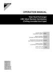
technical data
heat reclaim ventilation
VAM-FA8VE
VKM-GAMV1
VKM-GAV1
• HRV
TABLE OF CONTENTS
1
2
Part 1: VAM-FA8VE . . . . . . . . . . . . . . . . . . . . . . . . . . . . . . . . . . . . . . . . . . . . . . . . . . . . . . . . . . . . . . . . 3
1
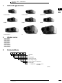
External appearance . . . . . . . . . . . . . . . . . . . . . . . . . . . . . . . . . . . . . . . . . . . . . . . 5
2
Model series . . . . . . . . . . . . . . . . . . . . . . . . . . . . . . . . . . . . . . . . . . . . . . . . . . . . . . . . . 5
3
Nomenclature . . . . . . . . . . . . . . . . . . . . . . . . . . . . . . . . . . . . . . . . . . . . . . . . . . . . . . . 5
4
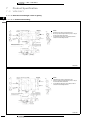
Structures . . . . . . . . . . . . . . . . . . . . . . . . . . . . . . . . . . . . . . . . . . . . . . . . . . . . . . . . . . . . 6
5
Features. . . . . . . . . . . . . . . . . . . . . . . . . . . . . . . . . . . . . . . . . . . . . . . . . . . . . . . . . . . . . . 7
6
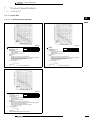
Selection Procedures. . . . . . . . . . . . . . . . . . . . . . . . . . . . . . . . . . . . . . . . . . . . . . 11
7
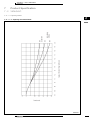
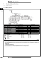
Product Specification . . . . . . . . . . . . . . . . . . . . . . . . . . . . . . . . . . . . . . . . . . . . . . 14
8
Operation . . . . . . . . . . . . . . . . . . . . . . . . . . . . . . . . . . . . . . . . . . . . . . . . . . . . . . . . . . 109
9
Control System . . . . . . . . . . . . . . . . . . . . . . . . . . . . . . . . . . . . . . . . . . . . . . . . . . . . 113
10
Installation . . . . . . . . . . . . . . . . . . . . . . . . . . . . . . . . . . . . . . . . . . . . . . . . . . . . . . . . . 137
Part 2: VKM-GA(M)V1
. . . . . . . . . . . . . . . . . . . . . . . . . . . . . . . . . . . . . . . . . . . . . . . . . . . . . . . . . . . 151
1
External Appearance . . . . . . . . . . . . . . . . . . . . . . . . . . . . . . . . . . . . . . . . . . . . . 153
2
Model Series . . . . . . . . . . . . . . . . . . . . . . . . . . . . . . . . . . . . . . . . . . . . . . . . . . . . . . 153
3
Nomenclature . . . . . . . . . . . . . . . . . . . . . . . . . . . . . . . . . . . . . . . . . . . . . . . . . . . . . 154
4
Structures . . . . . . . . . . . . . . . . . . . . . . . . . . . . . . . . . . . . . . . . . . . . . . . . . . . . . . . . . . 154
5
Features. . . . . . . . . . . . . . . . . . . . . . . . . . . . . . . . . . . . . . . . . . . . . . . . . . . . . . . . . . . . 155
6
Selection Procedures (in Japan) . . . . . . . . . . . . . . . . . . . . . . . . . . . . . . . . 163
7
Product Specification . . . . . . . . . . . . . . . . . . . . . . . . . . . . . . . . . . . . . . . . . . . . . 165
• HRV • Heat Reclaim Ventilation
1
• HRV
TABLE OF CONTENTS
1
2
2
8
Operation . . . . . . . . . . . . . . . . . . . . . . . . . . . . . . . . . . . . . . . . . . . . . . . . . . . . . . . . . . 204
9
Installation . . . . . . . . . . . . . . . . . . . . . . . . . . . . . . . . . . . . . . . . . . . . . . . . . . . . . . . . . 227
10
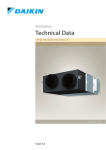
Outdoor Air Processing of Ceiling Mounted Duct
Connection Type . . . . . . . . . . . . . . . . . . . . . . . . . . . . . . . . . . . . . . . . . . . . . . . . . 247
11
Appendix. . . . . . . . . . . . . . . . . . . . . . . . . . . . . . . . . . . . . . . . . . . . . . . . . . . . . . . . . . . 251
• HRV • Heat Reclaim Ventilation
• HRV • VAM-FA8VE
TABLE OF CONTENTS
Part 1: VAM-FA8VE
1
External appearance . . . . . . . . . . . . . . . . . . . . . . . . . . . . . . . . . . . . . . . . . . . . . . . 5
2
Model series . . . . . . . . . . . . . . . . . . . . . . . . . . . . . . . . . . . . . . . . . . . . . . . . . . . . . . . . . 5
3
Nomenclature . . . . . . . . . . . . . . . . . . . . . . . . . . . . . . . . . . . . . . . . . . . . . . . . . . . . . . . 5
4
Structures . . . . . . . . . . . . . . . . . . . . . . . . . . . . . . . . . . . . . . . . . . . . . . . . . . . . . . . . . . . . 6
5
Features. . . . . . . . . . . . . . . . . . . . . . . . . . . . . . . . . . . . . . . . . . . . . . . . . . . . . . . . . . . . . . 7
Interlocked operation with VRV (SkyAir) . . . . . . . . . . . . . . . . . . . . . . . . . . . . . 7
Energy Saving . . . . . . . . . . . . . . . . . . . . . . . . . . . . . . . . . . . . . . . . . . . . . . . . . . . . . . . . 8
FRESH-UP operation . . . . . . . . . . . . . . . . . . . . . . . . . . . . . . . . . . . . . . . . . . . . . . . . . 9
Element (HEP element) . . . . . . . . . . . . . . . . . . . . . . . . . . . . . . . . . . . . . . . . . . . . . . 9
Easy Installation and service maintenance . . . . . . . . . . . . . . . . . . . . . . . . . . 10
Additional Optional accessories compared with EJ Series . . . . . . . . . . 10
6
Selection Procedures. . . . . . . . . . . . . . . . . . . . . . . . . . . . . . . . . . . . . . . . . . . . . . 11
Based on inhabitants
Based on Room size
7
. . . . . . . . . . . . . . . . . . . . . . . . . . . . . . . . . . . . . . . . . . . . . . . . 11
. . . . . . . . . . . . . . . . . . . . . . . . . . . . . . . . . . . . . . . . . . . . . . . . 11
Product Specification . . . . . . . . . . . . . . . . . . . . . . . . . . . . . . . . . . . . . . . . . . . . . . 14
Specifications . . . . . . . . . . . . . . . . . . . . . . . . . . . . . . . . . . . . . . . . . . . . . . . . . . . . . . . . 14
Optional accessories . . . . . . . . . . . . . . . . . . . . . . . . . . . . . . . . . . . . . . . . . . . . . . . . 19
The correction ratio of exchange efficiency . . . . . . . . . . . . . . . . . . . . . . . . . 88
Dimensions . . . . . . . . . . . . . . . . . . . . . . . . . . . . . . . . . . . . . . . . . . . . . . . . . . . . . . . . . . 89
Wiring diagram . . . . . . . . . . . . . . . . . . . . . . . . . . . . . . . . . . . . . . . . . . . . . . . . . . . . . . 94
Sound level data . . . . . . . . . . . . . . . . . . . . . . . . . . . . . . . . . . . . . . . . . . . . . . . . . . . . . 96
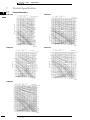
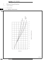
Fan performance . . . . . . . . . . . . . . . . . . . . . . . . . . . . . . . . . . . . . . . . . . . . . . . . . . . 102
Installation method . . . . . . . . . . . . . . . . . . . . . . . . . . . . . . . . . . . . . . . . . . . . . . . . . 104
8
Operation . . . . . . . . . . . . . . . . . . . . . . . . . . . . . . . . . . . . . . . . . . . . . . . . . . . . . . . . . . 109
Method of operation . . . . . . . . . . . . . . . . . . . . . . . . . . . . . . . . . . . . . . . . . . . . . . . . 109
Cautions in use . . . . . . . . . . . . . . . . . . . . . . . . . . . . . . . . . . . . . . . . . . . . . . . . . . . . . 111
Maintenance (for a qualified service person only) . . . . . . . . . . . . . . . . . . 111
Trouble shooting . . . . . . . . . . . . . . . . . . . . . . . . . . . . . . . . . . . . . . . . . . . . . . . . . . . . 112
9
Control System . . . . . . . . . . . . . . . . . . . . . . . . . . . . . . . . . . . . . . . . . . . . . . . . . . . . 113
Introduction of control system . . . . . . . . . . . . . . . . . . . . . . . . . . . . . . . . . . . . . . 113
Basic patterns . . . . . . . . . . . . . . . . . . . . . . . . . . . . . . . . . . . . . . . . . . . . . . . . . . . . . . 114
Applicable patterns . . . . . . . . . . . . . . . . . . . . . . . . . . . . . . . . . . . . . . . . . . . . . . . . . 124
Functions of Printed Circuit Board . . . . . . . . . . . . . . . . . . . . . . . . . . . . . . . . . . 134
Fan operation setting . . . . . . . . . . . . . . . . . . . . . . . . . . . . . . . . . . . . . . . . . . . . . . . 135
• HRV • Heat Reclaim Ventilation
3
• HRV • VAM-FA8VE
TABLE OF CONTENTS
Part 1: VAM-FA8VE
Pre -Operation flowchart . . . . . . . . . . . . . . . . . . . . . . . . . . . . . . . . . . . . . . . . . . .
Operation mode change over . . . . . . . . . . . . . . . . . . . . . . . . . . . . . . . . . . . . . .
10
136
Installation . . . . . . . . . . . . . . . . . . . . . . . . . . . . . . . . . . . . . . . . . . . . . . . . . . . . . . . . . 137
Reducing operating sound . . . . . . . . . . . . . . . . . . . . . . . . . . . . . . . . . . . . . . . . .
Centralized piping . . . . . . . . . . . . . . . . . . . . . . . . . . . . . . . . . . . . . . . . . . . . . . . . . .
Cautions . . . . . . . . . . . . . . . . . . . . . . . . . . . . . . . . . . . . . . . . . . . . . . . . . . . . . . . . . . . .
Cautions in installation . . . . . . . . . . . . . . . . . . . . . . . . . . . . . . . . . . . . . . . . . . . . .
Installation . . . . . . . . . . . . . . . . . . . . . . . . . . . . . . . . . . . . . . . . . . . . . . . . . . . . . . . . . .
Duct Work . . . . . . . . . . . . . . . . . . . . . . . . . . . . . . . . . . . . . . . . . . . . . . . . . . . . . . . . . .
Electrical wiring procedure . . . . . . . . . . . . . . . . . . . . . . . . . . . . . . . . . . . . . . . . .
Initial setting . . . . . . . . . . . . . . . . . . . . . . . . . . . . . . . . . . . . . . . . . . . . . . . . . . . . . . . .
4
135
• HRV • Heat Reclaim Ventilation
137
139
140
142
142
143
144
147
• HRV • VAM-FA8VE
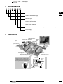
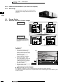
1
External appearance
1
1
VAM150FA8VE
VAM250FA8VE
VAM350FA8VE
VAM500FA8VE
VAM650FA8VE
VAM800FA8VE
VAM1000FA8VE
VAM1500FA8VE
VAM2000FA8VE
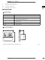
2
Model series
VAM150FA8VE
VAM250FA8VE
VAM350FA8VE
VAM500FA8VE
VAM650FA8VE
VAM800FA8VE
VAM1000FA8VE
VAM1500FA8VE
VAM2000FA8VE
3
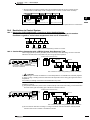
Nomenclature
V A M
500
F A VE
Ventilation
Air
Mounted type
Air flow rate (m3/ h)
Major design category
Design category for EC application
Power supply
VE: Single phase
50 Hz 220 – 240 V,
60 Hz 220 V
(HC0001)
• HRV • Heat Reclaim Ventilation
5
• HRV • VAM-FA8VE
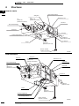
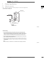
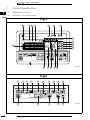
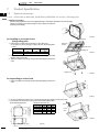
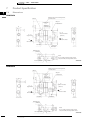
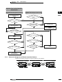
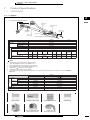
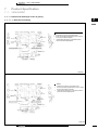
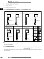
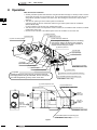
4
1
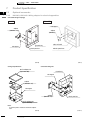
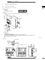
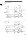
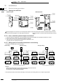
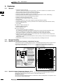
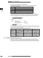
Structures
VAM150-1000FA
4
Heat exchange elements
Ceiling hock
Maintenance cover
OA
(Outdoor air)
[Fresh air from outdoor]
EA
(Exhaust air)
[Exhaust air to outdoor]
Switch box
Duct connection flange
Exhaust fan
Name plate
Air filter (Long life filter)
SA
(Supply air)
[Feed air to room]
Air supply fan
RA
(Return air)
[Exhaust air from room]
Damper
Remote controller
(Optional accessories)
(HC0238)
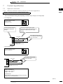
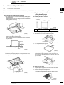
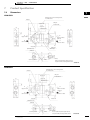
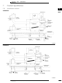
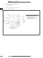
VAM1500,2000FA
Ceiling hock
Exhaust fan
Maintenance cover
OA
(Outdoor air)
[Fresh air from outdoor]
Switch box
Duct connection flange
EA
(Exhaust air)
[Exhaust air to outdoor]
Name plate
Air supply fan
SA
(Supply air)
[Feed air to room]
Damper
RA
(Return air)
[Exhaust air from room]
Air filter (Long life filter)
Heat exchange elements
Remote controller
(Optional accessories)
6
• HRV • Heat Reclaim Ventilation
(HC0016)
• HRV • VAM-FA8VE
5
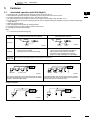
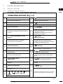
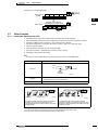
Features
5-1
1.
2.
3.
4.
5.
6.
7.
8.
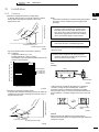
9.
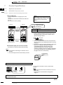
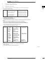
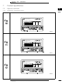
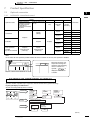
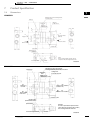
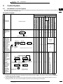
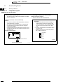
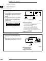
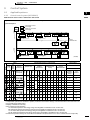
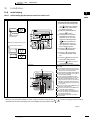
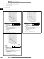
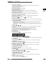
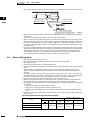
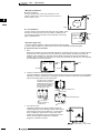
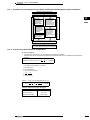
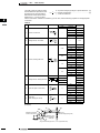
Interlocked operation with VRV (SkyAir)
Simultaneous ON / OFF with the indoor unit by the indoor unit remote control.
HRV independent operation during air conditioning off season by the indoor unit remote control.
Automatic ventilation mode changeover: Auto / Heat Recovery / Bypass
Fan speed changeover by the indoor unit remote control: High / Low, Ultra-High / High, Ultra-High / Low
Precooling / heating control function setting to delay the start of ventilation during air conditioner start-up to realize the high energy
saving efficiency.
FRESH-UP operation setting
Filter sign display notifies the time for cleaning the filter
No need to purchase or install the HRV exclusive remote control
Advantage to IAQ (Internal Air Quality.)
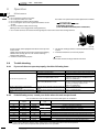
1
5
Note:
1. 5-7 can be set at the initial setting only.
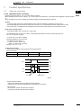
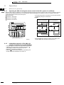
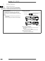
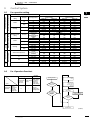
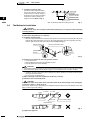
Type
Interlocked operation with air conditioner
HRV independent operation
Indoor
unit
Indoor
unit
HRV
Structure
Remote
Control
Features
HRV
Remote
Control
(HC0228)
Remote
Control
(HC0229)
• Both simultaneous operation by air conditioner’s
remote control and independent operation by
HRV exclusive remote control are available
• Fan speed can be changed by switch of HRV
(High / Low, High / Ultra-high, Low / Ultra-high)
• Simultaneous operation by air conditioner’s
remote control is available
• Fan speed can be set at the initial setting.
Connectable
Indoor unit VRV (all indoor unit), SkyAir (Optional connecting PCB is required.)
Other types
Daikin’s HRV
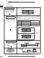
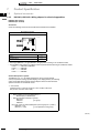
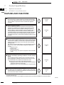
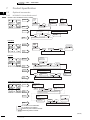
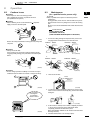
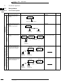
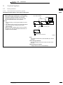
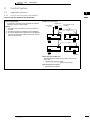
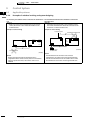
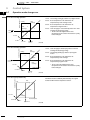
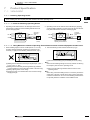
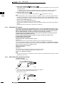
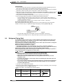
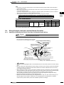
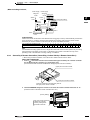
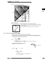
FAN mode
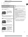
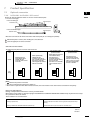
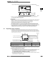
No falling of dust
OFF
Dust
(HC0006)
Dust does not fall off from the air filter because the air supply
fan of the interlocked indoor unit remains activated even when
the HRV is operated independently.
(HC0005)
If conventional HRV, with exclusive remote control, is directly
connected to indoor unit of air conditioner, dust may fall off
from air filter when air conditioner is OFF.
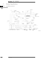
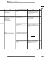
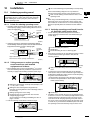
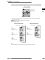
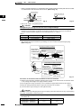
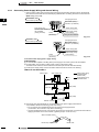
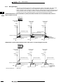
Installation Examples
Direct duct connection system
Independent duct system
(HC0007)
• HRV • Heat Reclaim Ventilation
(HC0008)
7
• HRV • VAM-FA8VE
1
5
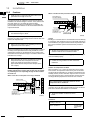
Features
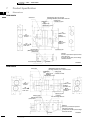
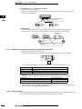
5-2
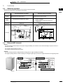
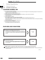
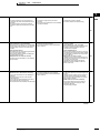
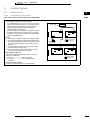
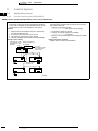
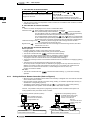
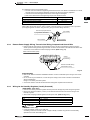
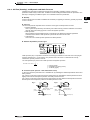
Energy Saving
5
By heat recovery operation
Approx. 20% reduction
of heating / cooling load
HRV unit recovers the thermal energy during cooling / heating operation of air
conditioner. HRV reduces the cooling / heating load drastically and enhances the
heating / cooling efficiency.
Exhaust Air
Return Air
Outdoor Air
Supply Air
Heat Exchanger Element
(Heat Recovery)
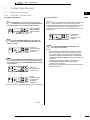
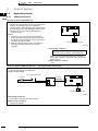
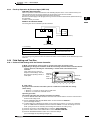
By setting to automatic
ventilation mode
Approx. 6% reduction
of heating / cooling load
(HC0230)
Proper use of Heat recovery ventilation and normal ventilation saves energy.
When the cooling operation is required in winter, use of heat recovery ventilation is
not efficient because the outdoor air temperature is normally lower than that of
the indoor.
Thus, the proper use of ventilation mode enhances the heating / cooling efficiency.
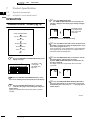
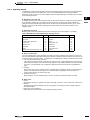
Automatic Ventilation mode changeover
Operation
Sensor of ventilation
Difference between
indoor / outdoor temp.
Decision of mode
(Which is more
energy efficient?)
Cooling
Indoor temp. > Outdoor temp Normal ventilation (Bypass)
Indoor temp. < Outdoor temp. Heat recovery ventilation
Heating
Indoor temp. > Outdoor temp. Heat recovery ventilation
Indoor temp. < Outdoor temp. Normal ventilation (Bypass)
Refer to the CONTROL for the mode changeover.
Heat Recovery mode
Exhaust Air
Return Air
Outdoor Air
Supply Air
Heat Exchanger Element
(Heat Recovery)
(HC0231)
Normal (Bypass) mode
Exhaust Air
Return Air
Outdoor Air
Supply Air
Heat Exchanger Element
(Heat Recovery)
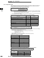
By Precooling / heating operation
Approx. 2% reduction
of heating / cooling load
Automatic
Changeover
(HC0232)
The load is reduced at startup of the air conditioner by the following control.
Before the working hour, the room air is clean.
Therefore, the startup of HRV can be delayed.
Working hour ends
Working hour starts
8:15
9:00
18:00
Air conditioner ON
OFF
HRV
OFF
ON
Cooling / Heating
load is reduced
Total
28% reduction
of heating / cooling
load
Reduction of
heating / cooling
load (%)
Normal
operation
HRV independent
operation
Interlocked
operation
Note:
1. The total heating / cooling load may vary depending on the climate or the other environmental conditions.
8
• HRV • Heat Reclaim Ventilation
(HC0233)
• HRV • VAM-FA8VE
5
Features
5-3
1
FRESH-UP operation
Both the excessive supply mode and the excessive exhaust mode are selectable.
This function creates a more comfortable air environment.
5
Supply Fresh-up
(Excessive outdoor air supply)
Detail
Major
effects
Exhaust Fresh-up
(Excessive Exhaust air supply)
Supply air volume can be set at a higher level than the
exhaust air by the remote control.
Exhaust air volume can be set at a higher level than the
supply air by the remote control.
• Prevents inflow of toilet odor
• Prevents inflow of outdoor air in winter
Application
• Prevents outflow of airborne bacteria from
rooms in a hospital
• Prevents outflow of odors from rooms in a
nursing home
Offices, etc.
Air supply
Air exhaust
HRV
Hospitals, Nursing homes, etc.
Portion
of exhaust
operation
Normal
ventilation fan
HRV
Air supply
Air exhaust
Example
Sick room
Floor area
Portion of fresh
up operation
ex. <Hospital>
ex. <Office>
(HC0010)
(HC0009)
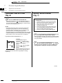
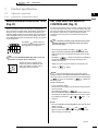
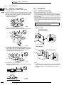
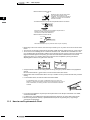
5-4
Element (HEP element)
Material
The heat exchanger element adopts a new paper of high permeability. The material recovers exhaust humidity at a speed of 2 times of
the previous model.
The material is flame-retardant for safety.
The fungiproof design also keeps the air clean.
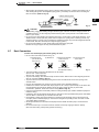
Structure
The heat exchanger element is designed without moving parts for higher durability and reliability.
The supply air passage and the exhaust air passage are arranged in right angle to prevent the supply and exhaust air from getting mixed.
Highly
Condensation
humid air
Paper
fiber
Less
humid air
Evaporation
water
Vapor
Liquid
Moisture absorbing liquid
Moisture
absorption
Move
through
capillary
Moisture
release
FA series
Permeation mechanism
Highly
humid air
Less humid air
water Vapor
Permeation mechanism
water
Vapor
EJ series
Moisture
absorption
Diffusion
Moisture
release
Porous particle
(Absorbent)
High moisture permeating speed
(HC0013)
• HRV • Heat Reclaim Ventilation
9
• HRV • VAM-FA8VE
5
1
5
Features
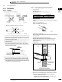
5-5
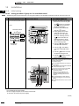
Easy Installation and service maintenance
Downsized
Total volume is reduced to 68% of EJ series and the unit fits into a small space.
(Comparison with FJ and previous EJ series)
Height
Model name
FJ
VAM 500FA
EJ
Height Difference
(mm)
Volume compared with
EJ series
285
←
310
–25
68%
VAM 800FA
348
←
388
–40
70%
VAM1000FA
348
←
388
–40
78%
VAM2000FA
710
←
790
–80
82%
Parallel air flow system (Daikin)
This system prevents misconnection and
simplify the installation work.
Cross air flow system
SA
EA
SA
EA
RA
OA
RA
OA
(HC0234)
(HC0235)
Service Maintenance
Switch Box
Access door
Maintenance cover
(HC0235)
Upside-down installation is available.
It allows the common use of the access door and reduces the space and installation work.
For 2 units closely installed, only one inspection hole of 450 × 450 mm will do for maintenance or replacement of the heat exchanger
element etc.
Long life filter is equipped.
5-6
Additional Optional accessories compared with EJ Series
Built-in optional high efficiency filter
It greatly reduces the installation space.
The installation of access doors and the unit can be reduced.
Direct expansion coil
HRV
unit
Drain
Direct expansion coil unit
Indoor unit
remote controller
outdoor unit
(HC0237)
The direct expansion coil helps to recover approx. 100% of exhaust air heat and prevents unpleasant draft. It can also operate as an air
conditioner.
Connectable unit: VRV and HRV.
BRP4A50
Refer to 6.16 Heater control kit (page 145) for the detail.
10
• HRV • Heat Reclaim Ventilation
• HRV • VAM-FA8VE
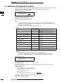
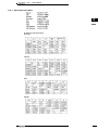
6
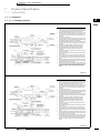
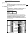
Selection Procedures
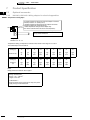
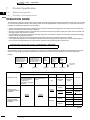
Various methods are used to calculate the required ventilating airflow rate according to CO2 generated by inhabitants in a room, waste gas
generated by use of fire, and other conditions of a room.
Here are 2 patterns of calculating methods.
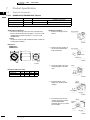
6-1
Based on inhabitants
Required ventilating
=
air flow rate (m3 / h)
6-2
A: 20 × Living room floor space (m2)
B: Area occupied per person (m2)
The above equation conforms to article 20, 2
No.2 of the Building Standards Act in Japan.
Note:
1. 20 (in the above equation) means “20(m3 / h / person)”,
which is the required ventilating air flow rate based on the
CO2 exhausted by an adult sitting still in a room. If smoking is
allowed, other calculation method should be used.
2. Use 10 (m2) if the area occupied per person exceeds 10 (m2).
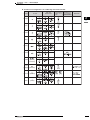
<Table 1>
Area occupied
per person (N)
Remarks
Eating houses,
restaurants,
coffee-shops
3 m2
Floor space of a part used for
business purposes.
Cabarets, beer
halls
2 m2
Floor space of a part used for
business purposes.
Type of building
Japanese-style
restaurants, hall
for hire
2
3m
Floor space of a part used for
business purposes.
Store market
3 m2
Floor space of a part used for
business purposes.
Pool rooms, Pingpong rooms,
dance halls,
bowling alleys
2 m2
Floor space of a part used for
business purposes.
2 m2
Floor space of a part used for
business purposes.
Pin-ball parlors,
Go club houses,
mahjong parlors
Inns, hotels, and
motels
10 m
Floor space of a part used for
business purposes.
Massage parlors
2
Floor space of a part used for
business purposes.
Meeting places,
public halls
Offices
2
5m
2
0.5 – 1 m
5 m2
Persons accommodated
simultaneously with the
number of persons calculated
per unit.
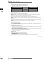
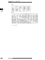
Required ventilating
= C×D×E
air flow rate (m3 / h)
C: Number of ventilation required per hour (ventilation / h)
D: Area of room (m2) (See Table 3 of the following page)
E: Height of Ceiling (m) (See table 2)
Calculation is based on the experiences of hygienic laboratory, etc.
to find out the number of hourly ventilation of the room air.
(Selection example)
Place: Living room of common household
Required ventilation: 6 times / h (See table 2)
Area of room: Approx. 9.9 (m2)
Height of ceiling: 2.4 m
Required ventilating air flow rate =
6 × 9.9 × 2.4 .=. 143 (m3 / h)
Required ventilating air flow rate and the unit size
such as 150, 250, 350 .............. 2000 are almost equal.
So select the close size of the unit.
In this case, select VAM150FJVE.
<Table 2>
Groups Type of room
Living room,
bathroom,
Common drawing room,
household toilet,
kitchen
Ventilation
required
6
6
6
10
15
Groups Type of room Ventilation
required
Playhouses
and movie
theaters
Audience room,
corridor,
smoking room,
toilet,
projector room
6
6
12
12
20
Plants
Office room,
general work
room,
telephone room,
spinning plant,
printing plant,
battery room,
machinery plant,
generator room,
substation room,
painting shop,
welding plant,
chemical plant,
food plant,
wood working
plant,
casting plant
6
6
6
10
10
10
10
15
15
15
15
15
20
20
50
Restaurant, sushi
restaurant,
banquet hall,
tempura
restaurant,
cooking room
6
6
10
Inns and
hotels
Guest room,
corridor,
dance hall,
large dining hall,
washroom, toilet,
cooking room,
laundry room,
engine room,
boiler room
5
5
8
8
10
15
15
20
20
6
6
6
10
10
10
10
10
15
15
15
15
20
20
Office room,
General waiting room,
buildings show room, toilet,
conference room
6
10
10
12
Hospitals
Consultation office,
sick room,
office room,
corridor,
waiting room,
bathroom,
dining room, toilet,
respiratory disease room,
laundry room,
cooking room,
surgery room,
sterilizing room,
engine room,
boiler room
Comfort
stations
20
Class room, library,
auditorium,
experimental
chemistry room,
gymnasium,
toilet,
cooking room
6
6
Room of potential noxious 20 or
gas or combustible gas
more
Eating
places
Floor space of an office.
*: Values set by the Metropolitan Maintenance Bureau in Japan.
Note:
1. Table indicates the required ventilating air flow rate
calculated as 20 m3 / h.
2. The area occupied per person by type of business is
calculated in reference to Application Standards for building
administration in compliance with Building Standards Act in
Japan.
6
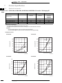
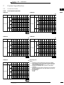
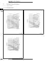
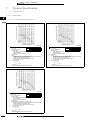
Based on Room size
20 × A
B
1
Schools
20
20
Dark
rooms
Dark rooms for
photo
Guest
rooms of
ship
16
6
6
8
12
15
Note:
Refer to the following pages for the tables.
• HRV • Heat Reclaim Ventilation
11
• HRV • VAM-FA8VE
1
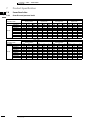
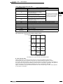
6
6
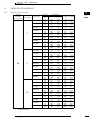
Selection Procedures
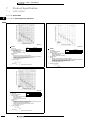
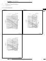
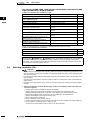
6-2
Based on Room size
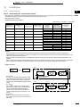
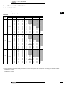
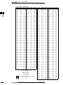
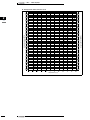
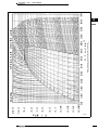
<Table 3> Criteria for Model Selection
Required
ventilating AFR
per person
(m3 / h / person)
Area per person
(m2 / person)
Frequency
Model Name
VAM 150FA
VAM 250FA
VAM 350FA
VAM 500FA
3
VAM 650FA
VAM 800FA
VAM1000FA
VAM1500FA
VAM2000FA
VAM 150FA
VAM 250FA
VAM 350FA
VAM 500FA
20
5
VAM 650FA
VAM 800FA
VAM1000FA
VAM1500FA
VAM2000FA
VAM 150FA
VAM 250FA
VAM 350FA
VAM 500FA
10
VAM 650FA
VAM 800FA
VAM1000FA
VAM1500FA
VAM2000FA
12
• HRV • Heat Reclaim Ventilation
Air Flow Rate
Application area (m2)
Hz
L
H
50
110
150
16.5
–
22.5
60
110
150
16.5
–
22.5
50
155
250
23.3
–
37.5
60
145
250
21.8
–
37.5
50
230
350
34.5
–
52.5
60
210
350
31.5
–
52.5
50
350
500
52.5
–
75.0
60
300
500
45.0
–
75.0
50
500
650
75.0
–
97.5
60
440
650
66.0
–
97.5
50
670
800
100.5
–
120.0
60
660
800
99.0
–
120.0
50
870
1000
130.5
–
150.0
60
800
1000
120.0
–
150.0
50
1200
1500
180.0
–
225.0
60
1200
1500
180.0
–
225.0
50
1400
2000
210.0
–
300.0
60
1400
2000
210.0
–
300.0
50
110
150
27.5
–
37.5
60
110
150
27.5
–
37.5
50
155
250
38.8
–
62.5
60
145
250
36.3
–
62.5
50
230
350
57.5
–
87.5
60
210
350
52.5
–
87.5
50
350
500
87.5
–
125.0
60
300
500
75.0
–
125.0
50
500
650
125.0
–
162.5
60
440
650
110.0
–
162.5
50
670
800
167.5
–
200.0
60
660
800
165.0
–
200.0
50
870
1000
217.5
–
250.0
60
800
1000
200.0
–
250.0
50
1200
1500
300.0
–
375.0
60
1200
1500
300.0
–
375.0
50
1400
2000
350.0
–
500.0
60
1400
2000
350.0
–
500.0
50
110
150
55.0
–
75.0
60
110
150
55.0
–
75.0
50
155
250
78.0
–
125.0
60
145
250
72.0
–
125.0
50
230
350
115.0
–
175.0
60
210
350
105.0
–
175.0
50
350
500
175.0
–
250.0
60
300
500
150.0
–
250.0
50
500
650
250.0
–
325.0
60
440
650
220.0
–
325.0
50
670
800
335.0
–
400.0
60
660
800
330.0
–
400.0
50
870
1000
435.0
–
500.0
60
800
1000
400.0
–
500.0
50
1200
1500
600.0
–
750.0
60
1200
1500
600.0
–
750.0
50
1400
2000
700.0
– 1000.0
60
1400
2000
700.0
– 1000.0
• HRV • VAM-FA8VE
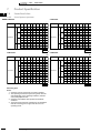
6
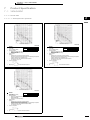
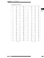
Selection Procedures
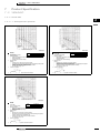
6-2
Based on Room size
Required
ventilating AFR
per person
(m3 / h / person)
Area per person
(m2 / person)
Frequency
Model Name
VAM 150FA
VAM 250FA
VAM 350FA
VAM 500FA
3
VAM 650FA
VAM 800FA
VAM1000FA
VAM1500FA
VAM2000FA
VAM 150FA
VAM 250FA
VAM 350FA
VAM 500FA
40
5
VAM 650FA
VAM 800FA
VAM1000FA
VAM1500FA
VAM2000FA
VAM 150FA
VAM 250FA
VAM 350FA
VAM 500FA
10
VAM 650FA
VAM 800FA
VAM1000FA
VAM1500FA
VAM2000FA
Note:
1.
1
Air Flow Rate
Application area (m2)
Hz
L
H
50
110
150
8.3
–
60
110
150
8.3
–
11.3
50
155
250
11.6
–
18.8
60
145
250
10.9
–
18.8
50
230
350
17.3
–
26.3
60
210
350
15.8
–
26.3
50
350
500
26.3
–
37.5
60
300
500
22.5
–
37.5
50
500
650
37.5
–
48.8
60
440
650
33.0
–
48.8
50
670
800
50.3
–
60.0
60
660
800
49.5
–
60.0
50
870
1000
65.3
–
75.0
6
11.3
60
800
1000
60.0
–
75.0
50
1200
1500
90.0
–
112.5
60
1200
1500
90.0
–
112.5
50
1400
2000
105.0
–
150.0
60
1400
2000
105.0
–
150.0
50
110
150
13.8
–
18.8
60
110
150
13.8
–
18.8
50
155
250
19.4
–
31.3
60
145
250
18.1
–
31.3
50
230
350
28.8
–
43.8
60
210
350
26.3
–
43.8
50
350
500
43.8
–
62.5
60
300
500
37.5
–
62.5
50
500
650
62.5
–
81.3
60
440
650
55.0
–
81.3
50
670
800
83.8
–
100.0
60
660
800
82.5
–
100.0
50
870
1000
108.8
–
125.0
60
800
1000
100.0
–
125.0
50
1200
1500
150.0
–
187.5
60
1200
1500
150.0
–
187.5
50
1400
2000
175.0
–
250.0
60
1400
2000
175.0
–
250.0
50
110
150
27.5
–
37.5
60
110
150
27.5
–
37.5
50
155
250
38.8
–
62.5
60
145
250
36.3
–
62.5
50
230
350
57.5
–
87.5
60
210
350
52.5
–
87.5
50
350
500
87.5
–
125.0
60
300
500
75.0
–
125.0
50
500
650
125.0
–
162.5
60
440
650
110.0
–
162.5
50
670
800
167.5
–
200.0
60
660
800
165.0
–
200.0
50
870
1000
217.5
–
250.0
60
800
1000
200.0
–
250.0
50
1200
1500
300.0
–
375.0
60
1200
1500
300.0
–
375.0
50
1400
2000
350.0
–
500.0
60
1400
2000
350.0
–
500.0
AFR: Air Flow Rate
• HRV • Heat Reclaim Ventilation
13
• HRV • VAM-FA8VE
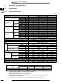
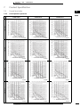
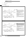
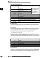
7
Product Specification
1
7-1
Specifications
7
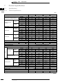
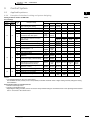
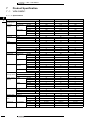
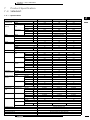
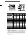
7-1-1
Technical specifications
(50Hz)
Model name
Power supply
VAM150FA
Ultra-High
High
Low
Ultra-High
High
Low
Ultra-High
High
Low
Temperature exchanging efficiency
Cooling
Enthalpy exchange
efficiency
Heating
Heat
exchange
mode
Normal input
Bypass mode
Heat
exchange
mode
Normal Amp.
Bypass mode
Casing
Insulating material
Dimensions
Heat exchanging system
Heat exchanging element
Air filter
Type
Fan speed
Fan
External static pressure
Ultra-high
High
Low
Ultra-high
High
Low
Ultra-high
High
Low
Ultra-high
High
Low
Heat exchange
mode
Bypass mode
%
%
%
%
%
%
%
%
%
74
74
79
58
58
64
64
64
69
W
W
W
W
W
W
A
A
A
A
A
A
H×W×D
VAM350FA
116
100
56
116
100
56
0.67
0.57
0.33
0.67
0.57
0.33
72
72
77
58
58
62
64
64
68
141
112
60
141
112
62
0.72
0.57
0.32
0.72
0.57
0.32
Galvanized steel plate
Self-extinguishable urethane foam
269 × 760 × 509
mm
75
75
80
61
61
67
65
65
70
269 × 760 × 509
Ultra-High
High
Low
Ultra-High
High
Low
Ultra-High
High
Low
Ultra-High
High
Low
285 × 812 × 800
m3 / h
m3 / h
m3 / h
Pa
Pa
Pa
Type
kW
dBA
dBA
dBA
dBA
dBA
dBA
150
150
110
69
39
20
250
250
155
64
39
20
350
350
230
98
70
25
Open type capacitor permanent split-phase induction motor, 4 poles × 2
0.030 × 2
27 – 28.5
26 – 27.5
20.5 – 21.5
27 – 28.5
26.5 – 27.5
20.5 – 21.5
0.030 × 2
28 – 29
26 – 27
21 – 22
28 – 29
27 – 28
21 – 22
0.090 × 2
32 – 34
31.5 – 33
23.5 – 26
32 – 34
31 – 32.5
24.5 – 26.5
–15 °C to 50 °CDB (80% RH or less)
Operation range (Ambient)
Connection duct diameter
Weight
Drawing number
φ 100
24
4D036749
mm
kg
φ 150
24
4D036750
φ 150
33
4D036751
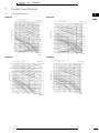
(HC0049)
Test conditions are as follows
Condition
Indoor
°CDB
Outdoor
R·H (%)
°CDB
R·H (%)
Cooling condition
27
50
35
60
Heating condition
20
40
7
70
Notes:
1. Operation sound is measured at 1.5 m below the center the body.
2. Fan speed can be changed over to Low mode or High mode.
3. Operating sound is measured in an anechoic chamber.
Operating sound level generally become greater than this value depending on the operating conditions,
reflected sound, and peripheral noise.
4. The sound level at the air discharge port is about 8 dB higher than the unit’s operating sound.
14
194
175
111
194
175
111
1.00
0.85
0.54
1.00
0.85
0.54
Air to air cross flow total heat (sensible heat + latent heat) exchange
Specially processed nonflammable paper
Multidirectional fibrous fleeces
Sirroco fan
Fan motor
Motor output
Sound pressure
level
VAM250FA
Single phase 220 – 240 V / 50Hz
• HRV • Heat Reclaim Ventilation
• HRV • VAM-FA8VE
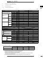
7
Product Specification
7-1
Specifications
7-1-1
Technical specifications
1
7
(50Hz)
Model name
Power supply
VAM500FA
Temperature exchanging efficiency
Cooling
Enthalpy exchange
efficiency
Heating
Heat
exchange
mode
Normal input
Bypass mode
Heat
exchange
mode
Normal Amp.
Bypass mode
Casing
Insulating material
Dimensions
Heat exchanging system
Heat exchanging element
Air filter
Type
Fan speed
Fan
External static pressure
Ultra-High
High
Low
Ultra-High
High
Low
Ultra-High
High
Low
Ultra-high
High
Low
Ultra-high
High
Low
Ultra-high
High
Low
Ultra-high
High
Low
Heat exchange
mode
Bypass mode
%
%
%
%
%
%
%
%
%
W
W
W
W
W
W
A
A
A
A
A
A
74
74
77
58
58
63
62
62
67
74
74
77
58
58
63
63
63
66
212
189
118
212
189
118
1.02
0.87
0.55
1.02
0.87
0.55
380
325
227
380
325
227
1.81
1.55
1.08
1.81
1.55
1.08
Galvanized steel plate
Self-extinguishable urethane foam
H×W×D
285 × 812 × 800
mm
348 × 988 × 852
Air to air cross flow total heat (sensible heat + latent heat) exchange
Specially processed nonflammable paper
Multidirectional fibrous fleeces
Sirroco fan
Ultra-High
High
Low
Ultra-High
High
Low
Fan motor
Motor output
Sound pressure
level
VAM650FA
Single phase 220 – 240 V / 50Hz
Ultra-High
High
Low
Ultra-High
High
Low
m3 / h
m3 / h
m3 / h
Pa
Pa
Pa
Type
kW
dBA
dBA
dBA
dBA
dBA
dBA
500
500
350
98
54
25
650
650
500
93
39
25
Open type capacitor permanent split-phase induction motor, 4 poles × 2
0.090 × 2
33 – 34.5
31.5 – 33
24.5 – 26.5
33.5 – 34.5
32.5 – 33.5
25.5 – 27.5
0.140 × 2
34.5 – 35.5
33 – 34
27 – 28
34.5 – 35.5
34 – 35
27 – 28.5
–15 °C to 50 °CDB (80% RH or less)
Operation range (Ambient)
Connection duct diameter
Weight
Drawing number
φ 200
33
4D036752
mm
kg
φ 200
48
4D036753
(HC0050)
Test conditions are as follows
Condition
Indoor
Outdoor
°CDB
R·H (%)
°CDB
Cooling condition
27
50
35
60
Heating condition
20
40
7
70
R·H (%)
Notes:
1. Operation sound is measured at 1.5 m below the center the body.
2. Fan speed can be changed over to Low mode or High mode.
3. Operating sound is measured in an anechoic chamber.
Operating sound level generally become greater than this value depending on the operating conditions,
reflected sound, and peripheral noise.
4. The sound level at the air discharge port is about 8 dB higher than the unit’s operating sound.
• HRV • Heat Reclaim Ventilation
15
• HRV • VAM-FA8VE
1
7
7
Product Specification
7-1
Specifications
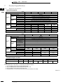
7-1-1
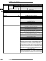
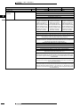
Technical specifications
(50Hz)
Model name
VAM800FA
VAM1000FA
Power supply
VAM1500FA
VAM2000FA
Single phase 220 – 240 V / 220 V, 50 / 60 Hz
Temperature exchanging efficiency
Cooling
Enthalpy exchange
efficiency
Heating
Ultra-High
%
74
75
75
75
High
%
74
75
75
75
Low
%
76
76.5
78
78
Ultra-High
%
60
61
61
61
High
%
60
61
61
61
Low
%
62
63
64
66
Ultra-High
%
65
66
66
66
High
%
65
66
66
66
Low
%
67
68
68
70
Power supply
Single phase 220-240 V, 50Hz / 220V, 60Hz
Heat exchange
mode
Normal Amp.
bypass mode
Heat exchange
mode
Normal input
bypass mode
Ultra-High
A
2.53
2.46
4.97
5.00
High
A
2.15
2.16
4.12
3.97
Low
A
1.79
1.74
3.43
3.27
Ultra-High
A
2.53
2.46
4.97
5.00
High
A
2.15
2.16
4.12
4.77
Low
A
1.79
1.74
3.43
3.27
Ultra-High
W
451
469
864
953
High
W
400
432
758
767
Low
W
346
349
655
653
Ultra-High
W
451
469
864
953
High
W
400
432
758
767
Low
W
346
349
655
653
Casing
Galvanized steel plate
Insulating material
Self-extinguishable urethane foam
H×W×D
Dimensions
mm
348 × 988 × 852
348 × 988 × 1140
710 × 1498 × 852
710 × 1498 × 1140
Heat exchanging system
Air to air cross flow total heat (sensible heat + latent heat) exchange
Heat exchanging element
Specially processed nonflammable paper
Air filter
Multidirectional fibrous fleeces
Type
Sirroco fan
Heat
exchange
mode
Fan
Air flow rate
Bypass mode
External static pressure
Ultra-High
m3 / h
800
1000
1500
2000
High
m3 / h
800
1000
1500
2000
Low
m3 / h
670
870
1200
1400
Ultra-High
m3 / h
800
1000
1500
2000
High
m3 / h
800
1000
1500
2000
Low
m3 / h
670
870
1200
1400
Ultra-High
Pa
137
157
137
137
High
Pa
98
98
98
78
Low
Pa
49
78
49
59
kW
0.230 × 2
0.230 × 2
0.230 × 4
0.230 × 4
Ultra-High
dBA
36 – 37
36 – 37
39.5 – 41.5
40 – 42.5
High
dBA
34.5 – 36
35 – 36
38 – 39
38 – 41
Low
dBA
31 – 32
31 – 32
34 – 36
35 – 37
Motor output
Heat
exchange
mode
Operating sound
Byapss mode
Ultra-High
dBA
36 – 37
36 – 37
40.5 – 41.5
40 – 42.5
High
dBA
34.5 – 36
35.5 – 36
38 – 39
38 – 41
Low
dBA
31 – 33
31 – 32
33.5 – 36
35 – 37
–15 °C to 50 °CDB (80% RH or less)
Operation range (Ambient)
Connection duct diameter
mm
φ 250
φ 250
φ 350
φ 350
Weight
kg
48
61
132
158
Operation mode
Heat exchange mode, bypass mode, freshup mode
Accessories
Drawing number
Operation manual, installation manual
4D036754
4D036755
4D036756
4D036835
(HC0051)
16
• HRV • Heat Reclaim Ventilation
• HRV • VAM-FA8VE
7
Product Specification
7-1
Specifications
7-1-1
Technical specifications
1
7
Test conditions are as follows
Condition
Indoor unit
Outdoor unit
°CDB
R·H (%)
°CDB
Cooling condition
27
50
35
60
Heating condition
20
40
7
70
R·H (%)
Notes:
1. Operation sound is measured at 1.5 m below the center the body.
2. Air flow rate can be changed over to Low mode or High mode.
3. Normal Amp., input, efficiency depend on the other above conditions.
4. Operating sound is measured in an anechoic chamber.
Operating sound level generally become greater than this value depending on the operating conditions,
reflected sound, and peripheral noise.
5. The noise level at the air discharge port is about 8 dBA higher than the unit’s operating sound.
6. The specifications, designs and information here are subject to change without notice.
• HRV • Heat Reclaim Ventilation
17
• HRV • VAM-FA8VE
1
7
7
Product Specification
7-1
Specifications
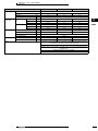
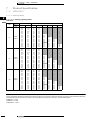
7-1-2
Electrical specifications
Units
Model name
Power supply
50Hz
60Hz
FM
MCA
MFA
kW
FLA
0.9
15
0.03 × 2
0.4 × 2
VAM250FA
0.9
15
0.03 × 2
0.4 × 2
VAM350FA
1.35
15
0.03 × 2
0.6 × 2
VAM150FA
VAM500FA
Power supply
Power supply
1.35
15
0.03 × 2
0.6 × 2
VAM650FA
max.264V
max. 242V
2.3
15
0.14 × 2
1.0 × 2
VAM800FA
min.198V
min.138V
3.4
15
0.23 × 2
1.5 × 2
VAM1000FA
3.4
15
0.23 × 2
1.5 × 2
VAM1500FA
6.75
15
0.23 × 4
1.5 × 4
VAM2000FA
6.75
15
0.23 × 4
1.5 × 4
SYMBOLS:
MCA: min. circuit amps. (A)
MFA: max. fuse amps. (A) (See note 5)
FM: fan motor
FLA: full load amps. (A)
kW: fan motor rated output (kW)
NOTES:
1. Voltage range units are suitable for use on the electrical systems where the voltage supplied to the unit terminals is not below or above
the listed range limits.
2. Maximum allowable voltage variation between phases is 2 %.
3. MCA/MFA
MCA = 1.25 × FLA(fm1) + FLA (fm2)
MFA ≤ 4 × FLA
(VAM2000FA5/8VE is regarded as 2 × VAM1000FA5/8VE)
4. Select wire size based on the value of MCA.
5. Instead of the fuse, use the circuit breaker.
4D036862
Specifications for field supplied fuses and wire
Model
VAM150FA
VAM250FA
VAM350FA
VAM500FA
VAM600FA
VAM800FA
VAM1000FA
VAM1500FA
VAM2000FA
18
Type
VE
Power supply wiring
Transmission wiring
Field supplied fuses
Wire
Size
Wire
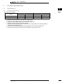
Size
15A
H05VV-U3G
Wire size must comply
with local codes.
Shield wire (2 wire)
0.75 – 1.25 mm2
• HRV • Heat Reclaim Ventilation
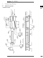
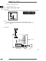
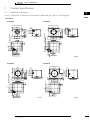
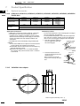
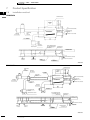
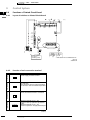
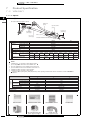
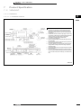
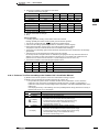
RA
(RETURN AIR FROM ROOM)
• HRV • Heat Reclaim Ventilation
INSPECTION HOLE
(FIELD SUPPLY)
METAL SUSPENSION BRACKET
FOR ABSORBING VIBRATION
(FIELD SUPPLY)
NOMINAL DIAMETER
SUSPENSION BOLT
(FIELD SYPPLY)
EA
(EXHAUST AIR TO OUTDOORS)
OA
(FRESH AIR FROM OUTDOORS)
A GRADIENT OF MORE
THAN ONE IN FIFTY
EA
(EXHAUST AIR TO OUTDOORS)
ROUND SHAPE HOOD
(FIELD SUPPLY)
Optional accessories
SA
(SUPPLY AIR TO ROOM)
AIR SUCTION GRILLE
K-DGL250A
HEAT INSULATOR
(FIELD SUPPLY)
(FRESH AIR FROM OUTDOORS)
OA
7-2
SUSPENSION BOLT POSITION
SUSPENSION
BOLT POSITION
FLEXIBLE DUCT
K-FDS252C
SILENCER
KDDM24A100
INPECTION
HOLE
Product Specification
AIR SUCTION GRILLE
K-DGL250A
BRANCH DUCT
KHA90B2
SUSPENSION
BOLT POSITION
7
SA
(SUPPLY AIR TO ROOM)
SUSPENSION BOLT
POSITION
AIR DISCHARGE
GRILLE
K-DGL200A
MAINTENANCE SPACE
• HRV • VAM-FA8VE
1
Installation example
7
19
• HRV • VAM-FA8VE
1
7
7
Product Specification
7-2
Optional accessories
Optional Accesories
Model
Item
Controlling
device
VAM150FA
Remote control
Wired remote controller
Central remote control
Centralized
controlling
Unified On/Off control
device
schedule timer
Duct adapter
Nominal pipe diameter (mm)
Duct adapter
Adapter for discharge
YAFF323F15
YAFF323F15
-
Model
Remote control
Wired remote controller
Central remote control
Centralized
controlling
Unified On/Off control
device
schedule timer
Wiring adapter for
electrical appandices
For humidifier
PC board
adapter
Installation box for
adapte PCB
For heater kit
VAM500FA
VAM650FA
YAFF323F35
YAFF323F35
-
VAM100FA
KDDM24A50
Ø 200
KDDM24A100
Ø 200
YAFF323F50
YAFF323F150
VKM50G
KDAJ25K36
YAFF323F65
YAFF323F65
VKM80G
KDA25K56
VAM1500FA
VAM2000FA
BRC301B61
BRC1D52
DCS302C51 (for general) DCS302C51 (For EC market)
DCS301B61 (for general) DCS301B51 (For EC market)
DST301B51 (for general) DST301B51 (For EC market)
KRP2A61 (for general) KRP2A51 (For EC market)
KRP50-2
KRP50-2A90 (Mounted electric component assy of HRV)
BRP4A50
Model name
Silencer
Nominal pipe diameter (mm)
Additional
function Air filter for replacement
High efficiency filter
Duct adapter
YAFF323F25
YAFF323F25
-
VAM800FA
Item
Controlling
device
VAM350FA
BRC301B61
BRC1D52
DCS302C51 (for general) DCS302C51 (For EC market)
DCS301B61 (for general) DCS301B51 (For EC market)
DST301B51 (for general) DST301B51 (For EC market)
KRP2A61 (for general) KRP2A51 (for EC market)
KRP50-2
KRP50-2A90 (Mounted electric component assy of HRV)
BRP4A50
PC board
adapter
Model name
Silencer
Nominal pipe diameter (mm)
Additional
function Air filter for replacement
High efficiency filter
VAM250FA
KDDM24A100
Ø 250
YAFF323F65
YAFF323F65
-
KDDM24A100
Ø 250
YAFF323F100
YAFF323F100
-
KDDM24A100x2
Ø 250
YAFF323F65x2
YAFF323F165x2
KDDM24A100x2
Ø 250
YAFF323F100x2
YAFF323F100x2
YDFA25A1
Ø 250
YDFA25A1
Ø 250
VKM80G
KDAJ25K56
KKM100G
KDAJ25K56
-
-
Nominal pipe diameter (mm)
Duct adapter
Adapter for discharge
Interlock adapter for VRV
Indoor unit
Adapter for wiring
Installation box for adapter PCB **
FXYC-K
KRP1B61 *
KRP1B96
Note 2,3
FXYK-K
KRP1B61
-
FXYF-K
KRP1B2 *
KRP1C98
Note 4
FXYS-K
FXYH-K
KRP1B61
-
-
FXYA-K
KRP1B3
KRP1B93
Note 3
FXYL(M)-KJ FXYM-K(J)
KRP1B61
-
-
Notes:
1. Installation box market with ** is required for each adapter marked *.
2. Up to 2 adapters can be fixed for each installation box.
3. Only one installation box can be installed for each indoor unit.
4. Up to 2 adapters can be fixed for each indoor unit.
5. Flexible duct size *** is for the duct from HRV unit to branch duct (or air outlet)
3TW24921-1A
20
• HRV • Heat Reclaim Ventilation
• HRV • VAM-FA8VE
7
Product Specification
7-2
Optional accessories
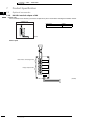
7-2-1
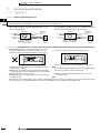
BRC301B61: Remote control
7-2-1-1
Remote control mounting instructions
1
7
1. Remove the upper part of remote control.
Insert minus screwdriver into the
slots in the lower part of remote
controller (2 places), and remove
the upper part of remote control.
The PC board is mounted in the
upper part of remote controller.
Be careful not to damage the board
with the minus screwdriver.
Upper Part of
Remote Controller
Lower Part of
Remote Controller
Minus screwdriver
Insert the minus
screwdriver and twist
lightly to remove.
2. Fasten the remote control.
1 For exposed mounting, fasten
with the included wood screws (2).
2 For flush-mounting, fasten with
the included machine screws (2).
Wood Screws
(φ 3.5 x 16)
Switch Box
(Field supplied parts)
Machine Screws
(M4 x 16)
For the field supplied switch box, use optional accessories KJB111A or KJB211A.
NOTE
Choose the flattest place possible for the mounting surface. Be careful not to
damage the shape of the lower part of remote controller by over-tightening the
mounting screws.
(HC0111)
2P034150
• HRV • Heat Reclaim Ventilation
21
• HRV • VAM-FA8VE
1
7
7
Product Specification
7-2
Optional accessories
7-2-1
BRC301B61: Remote control
7-2-1-1
Remote control mounting instructions
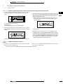
3. Wire the HRV unit.
NOTE
When wiring, run the wiring away the
power supply wiring in order to avoid
receiving electric noise (external
noise).
Connect the terminals on the upper part of the
remote
controller (P1, P2) and the terminals of the HRV unit
(P1, P2).
(P1 and P2 do not have polarity.)
HRV unit
HRV unit
Notch the part for the
wiring to pass through
with nippers, etc.
P2 P1
P2 P1
Ground the shielded
part on the HRV unit
Wiring Specifications
Shield Wire (2 wire) (See NOTE 3)
Wiring Type
Lower part
of Remote
controller
P C Board
0.75 – 1.25 mm2
Size
NOTE:
1. Peel the shield and sheath for the part that is to pass
through the inside of the remote controller case, as
shown in the figure below.
Peel the shield
and sheath.
P C Board
Upper Part
of Remote
controller
(Wired from the rear)
p
(Wired from the top)
4. Reattach the upper part of remote controller.
Be careful not to pinch the wiring when attaching.
NOTE
1. The switch box and wiring for connection are not
included.
2. Do not directly touch the PC board with your hand.
2. Treat the terminal for the wire to be connected to the
remote controller so the shielded part doesn't touch any
other part.
3. Sheathed wire may be used for transmission wirings, but
they do not comply with EMC (Electromagnetic
Compatibility) (European Directive). When using
sheathed wire. EMC must conform to Japanese
standards stipulated in the Electric Appliance Regulatory
Act. (If using a sheathed wire, the grounding shown in
the figure on the left is unnecessary.)
First, begin fitting
from the clips at the
bottom.
When controlling one HRV unit with two remote controllers
Change the MAIN/SUB changeover switch setting as described below.
P C Board
S
S
M
Main Remote
Controller
(Factory Set)
S
S
M
Sub Remote
Controller
Set one remote controller to “main,” and the other
to “sub.”
NOTE
• If controlling with one remote controller, be sure to set
it to “main.”
• Set the remote controller before turning power
supply on.
“ 88 ” is displayed for about one minute when the power supply is turned on, and the remote controller cannot be
operated in some cases.
(HC0112)
2P034150
22
• HRV • Heat Reclaim Ventilation
• HRV • VAM-FA8VE
7
Product Specification
7-2
Optional accessories
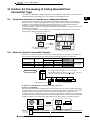
7-2-2
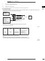
KRP50-2: Wiring adapter for remote contact / Humidifier
KRP50-2A90: Installation box for adapter PCB
Components
1. KRP50-2 PCB (×1)
2. PCB catches (4 large, 4 small)
1
7
2 KRP50-2 can also be connected to SkyAir indoor unit for the
interlocked operation with HRV units. Or to be connected
and used for the adapter for outside air preheater.
Components
See the right for components.
(16)
Fixing Screw
3 PCS.
Clamp
2 PCS.
(5)
Installation
Either large or small catches
are used, depending on the
model
(HC0113)
Install the Adapter PCB to the outside of switch box.
for HRV unit as show below.
(HC0114)
Tie wrap .........(×1)
Fixing Screw
Manual ............(×1)
Fixing Board
Installation guide
PCB Support
(Attached to
Adapter PCB)
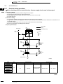
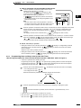
1 The KRP50-2 can be connected to HRV units as follows to
send the operation signal (pilot lamp etc.) to remote
locations.
Electric wiring is as follows.
• For Remote contact
KRP50-2A90
Power supply
(1 φ 220 ~ 240 V)
Pilot lamp
(Operation display)
Switch Box
J1 J2 JC
L
1
3P connector
2P connector
2
X9A SS1
X10A
F1 F2
X11A
3
Lid
P1 P2
Fixing Screw
HRV unit
KRP50-2
P1 P2
Remote control
for HRV unit
Applicable adapter
Adapter name
(HC0253-1)
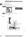
• For Humidifier
J1 J2 JC
YC
1
Float
switch
A
B
3P connector
2P connector
2
X9A SS1
X10A
3
Adapter PCB for Humidifier
KRP50-2
(2)
Adapter PCB for Remote control
KRP2A61
F1 F2
X11A
P1 P2
Y2
HRV unit
KRP50-2
Humidifier
(1)
4P055444
Power supply
(φ 1 100 V or 200 V)
SV
Kit name
Humidity Controller
(Field supplied)
P1 P2
Remote control
for HRV unit
(HC0115-1)
• HRV • Heat Reclaim Ventilation
23
• HRV • VAM-FA8VE
1
7
7
Product Specification
7-2
Optional accessories
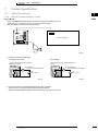
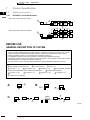
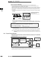
7-2-3
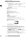
KRP2A51, KRP2A61: Wiring adapter for electrical appendices
KRP2A51 (For Europe)
KRP2A61 (For General)
Accessories
Check the following accessories are included in the kit before the installation.
Wiring Adapter for Electrical
Appendices (1)
×1
PCB support
×4
Clamp
×3
Installation Manual
×1
Notes:
• The kit type (KRP2A61 • 51 type, KRP2A62 • 52 type) varies according to air conditioner model.
• The installation plate and box for adapter PCB are required with the following air conditioner models.
FXYFP ...................KRP1A90 or KRP1B94
FXYFP ...................KRP1C98
FXH ........................KRP1B93
FXYCP ..................KRP1B96
General description of system
The KRP2A61 • 62 • 51 • 52 enables operation by remote control (ON/OFF
control, temperature setting, operation display, error display). With it, the following
system can be built. Note however that the adapter cannot be used with other
optional controllers for centralized control.
1. Zone control
(Unified control of a max. 64 groups of a max. 16 indoor units each.
But, the max. of indoor units is 128.)
This system requires the following parts.
• Wiring Adapter for Electrical Appendices (1)
…KRP2A61(62) or KRP2A51(52)
• Remote controller switches (For control)
…BRC1C517
⎫
⎬ Per group
BRC2A51
⎭
BRC3A61
(Ex.) Zone control for 8 FXYC63KVE units (control groups of 4, 3 and 1)
KRP2A51 × 1 kit
⎫
⎬ (1 set required for each group.)
BRC1C517 × 3 kits
⎭
(HC0116)
24
• HRV • Heat Reclaim Ventilation
• HRV • VAM-FA8VE
7
Product Specification
7-2
Optional accessories
7-2-3
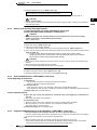
KRP2A51, KRP2A61: Wiring adapter for electrical appendices
1
7
Indoor unit
To host computer
monitor panel etc.
Max. 16 unit
Remote controller
Max. 64 groups
Max. 16 unit
To outdoor unit
Notes:
Individual indoor units connected to the centralized line cannot be displayed individually.
Names of parts and functions
Display output terminal board (X2M)
Connects operation and error output to a
remote
point (host computer monitor panel, etc.).
Trouble monitor (H10P: RED)
Microcomputer normal monitor
(HAP: GREEN)
Flickers when the microcomputer
is operating normally.
Lights up when trouble occurs
in electrical wiring or parts.
Remote control is disabled.
(LED is out in normal
Control mode selector switch (RS1)
(Factory set: 0)
For selecting how to operate the
system via remote.
Power supply connector (D1, D2)
W1
To adapter power supply connector
(X18A)
W2
W3
W4
Temperature setting ON/OFF switch (SS2)
(Factory set: P)
I To enable temperature setting with the
remote controller, set to “Inhibit”.
P To set temperature setting only by
SS3
remote control, set to “Permission”.
Display output switch (SS3) (Factory set: Z)
Transmission wiring (F1, F2)
To display all control units as unified
zone, set to “Zone”.
Z
To F1 and F2 on indoor unit terminal
board
I
B1 B2 BC
A+
A–
SS3
(Factory set)
Input changeover switch (SS1)
(Factory set: VOLT)
Set according to the type of input (voltage/
non- voltage) sent to remote control input
terminal board (X1M).
Remote control input
terminal board (X1M)
Connects control input from
remote (host computer
monitor panel, timer, etc.).
Note: Do not set to “Individual”.
This will cause a system error (H10P
flashes.)
Temperature setting input terminals (A+,
Temperature setting is determined by a
resistance value between 0 and 135 Ω.
NEVER apply voltage to this terminal for
any reason whatsoever.
For details,
see the wiring
diagram
(HC0117)
• HRV • Heat Reclaim Ventilation
25
• HRV • VAM-FA8VE
1
7
7
Product Specification
7-2
Optional accessories
7-2-3
KRP2A51, KRP2A61: Wiring adapter for electrical appendices
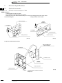
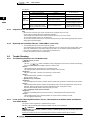
Installation
Ceiling mounted corner cassette
Adapter
(KRP2A61
KRP2A51)
Electric parts box
PCB support
P board ass’y
(HC0118)
4-way blow ceiling mounted cassette
Lid of PCB Box
(Option KRP1C98)
Adapter
(KRP2A62-52)
PCB Support
Box for adapter PCB
(Option KRP1C98)
Note:
To install the adapter.
Box for adapter PCB (option) is required.
(HC0119)
26
• HRV • Heat Reclaim Ventilation
• HRV • VAM-FA8VE
7
Product Specification
7-2
Optional accessories
7-2-3
KRP2A51, KRP2A61: Wiring adapter for electrical appendices
1
7
2-way blow ceiling mounted cassette
Box for adapter PCB
(Option KRP1C98)
Electric parts box
Installation
screw
PCB support
Adapter
P board ass’y
(KRP2A61 • 51)
Note:
A separate plate is needed to install
the adapter PCB.
(HC0247)
Wall mounted unit
* A malfunctin could
occur is not clamped.
PCB support
Adapter
(KRP2A61 • 51)
Approx.
150
Clamp as shown in
the above drawing.
Indoor unit PCB ass’y
Electric parts box
(HC0120)
• HRV • Heat Reclaim Ventilation
27
• HRV • VAM-FA8VE
1
7
7
Product Specification
7-2
Optional accessories
7-2-3
KRP2A51, KRP2A61: Wiring adapter for electrical appendices
Concealed ceiling unit (large)
200 • 250
40-125
PCB support
Adapter
(KRP2A61 • 51)
Adapter
(KRP2A61)
Indoor PC board
P board ass’y
PCB support
Electric parts box
Electric parts box
(HC0248)
Ceiling suspended unit
(V0219)
Concealed ceiling unit
Box for adapter PCB
(option KRP1B93)
P board ass’y
PCB support
Adapter
(KRP2A62 • 52)
PCB support
Adapter
(KRP2A61 • 51)
Electric parts box
Box for adapter PCB
(option KRP1B93)
Note:
A separate plate is needed to install the adapter
PCB.
(HC0249)
28
• HRV • Heat Reclaim Ventilation
(HC0121)
• HRV • VAM-FA8VE
7
Product Specification
7-2
Optional accessories
7-2-3
KRP2A51, KRP2A61: Wiring adapter for electrical appendices
1
7
(Concealed) floor standing unit
P board ass’y
PCB support
Electric parts box
Adapter
(KRP2A61 • 51)
(HC0250)
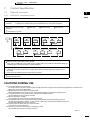
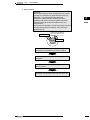
Electrical wiring
1. First, wire between the indoor and outdoor units, then to the separate power
sources, and between the indoor units and the remote controllers. Then, check
wiring is correct. (If wanting group control by remote controller, check transmission
wiring.) For details, see the installation manual of the indoor and outdoor units.
2. Next, wire between the wiring adaptor for electrical appendices (1) and the indoor
units. For details, see Wiring to indoor units.
3. Finally, wire between external units such as the host computer monitor panel, and
make the necessary settings. For details, see Wiring to external units (host computer
monitor panel).
Note:
It is not necessary to set address No. for centralized control. (Setting is automatic.)
(HC0122)
• HRV • Heat Reclaim Ventilation
29
• HRV • VAM-FA8VE
1
7
7
Product Specification
7-2
Optional accessories
7-2-3
KRP2A51, KRP2A61: Wiring adapter for electrical appendices
Wiring to indoor units
1. For zone control
Be sure to set to “ZONE”
Z
SS
3
X18A
PC board ass’y
I
DISPLAY OUTPUT
Adapter
PCB
P1,P2 F1,F2
P1,P2 F1,F2
P1,P2 F1,F2
Max. 16 units
R/C
Remote controller
P1,P2 F1,F2
P1,P2 F1,F2
P1,P2 F1,F2
Max. 16 units
R/C
Remote controller
P1,P2 F1,F2
Max.
64 groups
R/C
Remote controller
(Wiring specifications)
Wiring .... Sheathed wire (2-wire)
Gauge .... 0.75 ~ 1.25 mm2
Length .... Max. 1000 m
< IMPORTANT >
Keep transmission wiring at least 50 mm away from power
supply wiring to avoid malfunctions.
(HC0123)
30
• HRV • Heat Reclaim Ventilation
• HRV • VAM-FA8VE
7
Product Specification
7-2
Optional accessories
7-2-3
KRP2A51, KRP2A61: Wiring adapter for electrical appendices
1
7
Wiring to external units (host computer monitor panel)
1. Remote control input (operation control)
Wire as described below. Wiring differs depending on whether using a voltage or non-voltage input.
• For voltage input
Set input changeover switch
(SS1) to “VOLT”.
(Factory set: VOLT)
NON
VOLT
VOLT
CHANGE OVER
Use a 12-24 V external power supply.
Each contact requires approximately 10 mA,
therefore carefully select power supply
capacity.
Connect the control input to
the common contact (nonpolarity).
Use a micro-current contact
of a minimum current load of
12 V, 1 mA or less.
DC12-24V
G
BC
Input B
B2
Input A
B1
Wiring adapter
KRP2A61 • 62 • 51 • 52
• For non-voltage input
Set input changeover switch
(SS1) to “NON VOLT”.
NON
VOLT
VOLT
CHANGE OVER
Use a micro-current contact
of a minimum current load of
12 V, 1 mA or less.
DC12-24V
BC
G
Input B
B2
Input A
B1
Wiring adapter
KRP2A61 • 62 • 51 • 52
(Wiring specifications)
Wiring .... Sheathed wire
Gauge .... 0.18 ~ 1.25 mm2
Length .... Max. 150 m
< IMPORTANT >
Keep transmission wiring at least 50 mm away from power
supply wiring to avoid malfunctions.
(HC0124)
• HRV • Heat Reclaim Ventilation
31
• HRV • VAM-FA8VE
1
7
7
Product Specification
7-2
Optional accessories
7-2-3
KRP2A51, KRP2A61: Wiring adapter for electrical appendices
2. Setting control mode selector sitch (RS1)
RS1
CONTROL MODE
Using control mode selector switch (RS1),
select the control mode as described below.
Factory set:
“0” position
1. When operating with only individual display function
Position
Function
0
Individual display
(input ignored)
2. When operating with constant input from A
Position
Contents when input A is
ON
Function
1
Remote
controller
rejection
Operation (remote
controller is normally
rejected)
2
Central
priority
Operation + remote
controller accepted
3
Stop by
remote
controller
acceptable
Operation + stop by remote
controller acceptable (No
operation by the remote
controller)
4
Remote
controller
acceptance/
rejection
Remote controller
acceptance only (No
operation by the remote
location)
Contents when
input A is OFF
Stop + remote
controller
rejection
Note:
• Input B is for forced-OFF. When ON, stop + remote controller is rejected, and input A is ignored. When OFF, even if A is ON, the contents
of when input A is ON are not achieved. Input A must therefore be re-input.
3. When operating with momentary input from A
(Use a momentary input of ON time 200 mili-sec or longer.)
Position
Function
Contents of Input A
5
Remote
controller
rejected
Stop for ON while
operating, Operate for ON
while
stopping
Last
command
priority
Stop for ON while
operating, Operate for ON
while
stopping (Remote
controller is normally
accepted.)
6
Function of Input B
Input B will be forced
stop function (When
ON, stop + remote
controller is rejected,
input A is ignored.)
(HC0125)
• For demand control from input B
32
• HRV • Heat Reclaim Ventilation
• HRV • VAM-FA8VE
7
Product Specification
7-2
Optional accessories
7-2-3
KRP2A51, KRP2A61: Wiring adapter for electrical appendices
1
7
• For demand control from input B
Position
C
D
E
F
Function when input A is ON
Remote controller rejected
(Same as position “5”)
Last command priority
(Same as position “6”)
Function when input B is ON
Forced thermostat OFF command
Forced temperature shift command
Forced thermostat OFF command
Forced temperature shift command
• Forced thermostat OFF command
Forces indoor unit to operate the fan only
• Forced temperature shift command
The indoor unit operates at 2 C higher (cooling) or 2 C lower (heating) than the set temperature.
Notes:
• In zone control, operation is displayed as long as one indoor unit is running.
When in the last command priority mode, some units are not operation while ON.
• In such case, even if input A is ON, the unit and all other units in the same zone will stop.
4. When operating with dual momentary inputs from A and B
(Use a momentary input of 200 mili-sec or longer.)
Position
Function
Contents when input A
is ON
7
Remote
controller
rejection
Operation (remote
controller is normally
rejected)
8
Central
priority
Operation + remote
controller accepted
9
Stop by
remote
controller
acceptable
Operation + stop by
remote controller
acceptable (No operation
by the remote controller)
A
Remote
controller
acceptance/
rejection
Remote controller
acceptance only (No
operation by the remote
location)
B
Last
command
priority
Operation (remote
controller is normally
accepted)
Contents when
input A is OFF
Stop + remote
controller rejection
Stop (remote
controller normally
accepted)
Note:
• Doing constant input A with position 7 to A, it will be forced OFF function
(input A is ignored.)
• Constant input cannot use for input B with position B.
(HC0126)
• HRV • Heat Reclaim Ventilation
33
• HRV • VAM-FA8VE
1
7
7
Product Specification
7-2
Optional accessories
7-2-3
KRP2A51, KRP2A61: Wiring adapter for electrical appendices
3. Temperature setting input
To enable temperature setting from both the adapter and remote
controller, set SS2 to “P”. (Factory set: P)
P: Enables temperature setting by both the adapter and remote
controller. (Engages last command priority.)
I: Enable temperature setting from the adapter only.
(The remote controller cannot be used to set temperature.)
SS2
I
P
A
A+
NEVER apply voltage to tarminals A+ or Afor any reason whatsoever.
Wiring adapter
KRP2A61 • 62 • 51 • 52
Temperature setting corresponds to resistance values values in the range of 0 to 135 Ω.
Their relationship is as shown below
Temperature
setting ( C)
16
17
18
19
20
21
22
23
24
Resistance (Ω)
0.0
|
3.4
5.0
|
11.6
13.8
|
20.0
22.4
|
28.4
31.0
|
36.4
39.4
|
44.8
48.2
|
52.8
56.6
|
61.2
65.2
|
69.4
Temperature
setting ( C)
25
26
27
28
29
30
31
32
Resistance
(Ω)
73.8
|
77.8
82.4
|
85.8
91.0
|
94.0
99.4
|
102.2
108.6
|
110.4
117.2
|
119.2
125.8
|
127.4
134.2
|
140.0
Note:
Wiring resistance included in above figures.
(Wiring specifications)
Wiring .... Sheathed wire
Gauge .... 1.25 ~ 2.00 mm2
Length .... Max. 70m
< IMPORTANT >
Keep transmission wiring at least 50 mm away from power
supply wiring to avoid malfunctions.
34
• HRV • Heat Reclaim Ventilation
• HRV • VAM-FA8VE
7
Product Specification
7-2
Optional accessories
7-2-3
KRP2A51, KRP2A61: Wiring adapter for electrical appendices
1
7
4. Cancelling display signals
Operation output terminals (W1 and W2) and malfunction output terminals (W3 and W4) are non-voltage constant contact output.
(Allowed electric current per contact is between 10 mA and 3A.)
Normal operation
output (Ry1)
ON when the unit is
operating normally.
W1
Operation display
Ry1
W2
Malfunction output
(Ry2) ON when the unit
stops because of
malfunction or when a
malfunction
of transmission occurs
between the adapter
Power source
Ry2
W3
Error display
DC24V
AC24V
AC220
~ 240V
W4
Wiring adapter
KRP2A61 • 62 • 51 • 52
Note:
If using a 220 ~ 240 V power supply, keep transmission wiring at least 50 mm away
from incoming power supply wiring.
(HC0127)
Output
System
Zone
control
Both Ry1
and Ry2
OFF
Ry1 only ON
All zones
OFF
At least one unit
running normally,
no malfunction
Ry2 only ON
Even 1 unit stopped due
to malfunction or
malfunction of
transmission between
adapter and indoor unit
Display output is described by system in the below table.
Note:
If rewiring F1 and F2 after running the system, turn ON power for 5 minutes, then turn
it OFF and ON again. Changes to wiring can sometimes disable control from the wiring adapter.
(HC0128)
1PA63642B
• HRV • Heat Reclaim Ventilation
35
• HRV • VAM-FA8VE
1
7
7
Product Specification
7-2
Optional accessories
7-2-4
KRP1B61: Interlock adapter of VRV
Accessories
Check if the following accessories are included in the kit.
Adapter
X1
PC board support
×4
Clamp
×3
Installation manual
×1
(HC0129)
Notes
• Kits vary according to applicable models.
• A special adapter fixing plate and box are required for the following
models.
FXYCP.........................KRP1B96
Names of parts
X2A
Terminals for installing optional
accessories
F1U F2U
Terminals for operation
display
X1A
250 V, 5 A
(HC0130)
36
• HRV • Heat Reclaim Ventilation
• HRV • VAM-FA8VE
7
Product Specification
7-2
Optional accessories
7-2-4
KRP1B61: Interlock adapter of VRV
1
7
Electric Wiring
• Refer to the WIRING DIAGRAM attached to the indoor unit before attempting to wire.
[Make sure wires to units do not pass over the PC board when wiring.]
• Wire the adapter to the indoor unit as shown below,
X2A
X16A
Indoor unit PC board
X1A
Blue
N
L
Red
(HC0131)
1. Fetching the operation display signal
• Attaching an hour meter
• Fan ON display
Output is generated at the contact while the
compressor is running.
HM: Hour meter
(Part to be procured in the field)
Example :
X1
Output is generated at the contact while the fan is
running.
HM
RL: Operation lamp
(Part to be procured in the field)
Example :
X3
RL
AC
220 – 240 V
AC
220 – 240 V
X4
X2
(HC0132)
(HC0133)
2. If optional accessories are installed (auxiliary electric heater, humidifier)
• Wire correctly in accordance with the attached installation manual.
• Refer to the wiring diagram applied to the indoor unit when running electric wiring.
• HRV • Heat Reclaim Ventilation
37
• HRV • VAM-FA8VE
1
7
7
Product Specification
7-2
Optional accessories
7-2-4
KRP1B61: Interlock adapter of VRV
Installation
• Installation differs according to models.
• Do not bundle low and high voltage wires together.
• Bundle any access wires with the attached clamps so as to keep loose wirings off the indoor unit PC board.
Concealed ceiling unit
Ceiling mounted corner cassette
Indoor PC board
Adapter
(KRP1B61)
PCB support
PCB support
Electric parts box
Indoor PC board
Electric parts box
Adapter
(KRP1B61)
(HC0134)
(HC0135)
2-way blow ceiling mounted cassette
Plate for adapter PCB
(option KRP1B96)
PCB support
Installation screw
Adapter
(KRP1B61)
Indoor PC board
Electric parts box
NOTE:
38
A separate plate is needed to install the
adapter PCB.
• HRV • Heat Reclaim Ventilation
(HC0136)
• HRV • VAM-FA8VE
7
Product Specification
7-2
Optional accessories
7-2-4
KRP1B61: Interlock adapter of VRV
1
7
Concealed ceiling unit (large)
40 ~ 125
200 ~ 250
Indoor PC board
Electric parts box
Adapter
Indoor PC board
(KRP1B61)
PCB support
PCB support
Adapter
(KRP1B61)
Electric parts box
(HC0137)
(HC0138)
(Concealed) floor standing unit
Indoor PC board
PCB support
Electric parts box
Adapter (KRP1B61)
(HC0139)
Ceiling suspended unit
PCB support
Adapter
(KRP1B61)
Indoor PC board
Electric parts box
(HC0140)
• HRV • Heat Reclaim Ventilation
39
• HRV • VAM-FA8VE
1
7
7
Product Specification
7-2
Optional accessories
7-2-5
KRP1B2: Interlock adapter of VRV
Contents of kit
Prior to installation check whether you have the complete kit of parts as shown below including the installation manual.
PC board support
Plastic straps
Installation manual
Adapter PCB for wiring
1 set
4 pieces
3 pieces
1 piece
(HC0142)
Notes:
• Be careful with the selection of the optional kit, which varies depending on the model.
• For the installation of the following optional kit, it also requires the adapter fixing plate and box.
FXYFP .........................KRP1C98
Names of parts
CN2
Optional kit connecting
terminal
FuS FuR
Display output terminal
CN1
250 V, 5 A
(HC0143)
40
• HRV • Heat Reclaim Ventilation
• HRV • VAM-FA8VE
7
Product Specification
7-2
Optional accessories
7-2-5
KRP1B2: Interlock adapter of VRV
1
7
Electrical wiring
• Refer to the wiring diagram of the indoor unit for it’s wiring connection.
(Make sure all the wiring to the unit should not go over the PC board.)
• Connect the wiring to the indoor unit as shown below.
· CN33 ............For SkyAir
· CN16 ............For VRV
CN2
CN1
White
3S
Black
1R
For SkyAir............................. Connect to no.1 and no.3 of the
terminal board of the indoor unit
For VRV................................. Connect to R and S of the
terminal board of the indoor unit
(HC0144)
1. To detect the operation display signal
• Installation of the watt-hour meter
• The fan display signal
Output signal to detect the operation of the
compressor
HM: Hour meter
(local supply)
Example :
X1
Output signal to detect the operation of the fan
RL: Operation lamp
(local supply)
Example :
X3
HM
RL
AC
220 – 240 V
X2
AC
220 – 240 V
X4
(HC0132)
(HC0133)
2. In case other optional kits are installed. (auxiliary electric heater, humidifier and fresh air intake kit)
• Connect the wiring properly according to the installation manual included in the kit.
• Refer to the wiring diagram of the indoor unit for it’s wiring connection.
Installation
• Never bundle high and low voltage wiring together.
• Be sure to bundle the excess wring with the attached plastic strap so as to keep the loose wiring off the indoor unit PC board.
4-way blow model
Lid of PCB Box
(Option KRP1C98)
Adapter
(KRP2A62-52)
PCB Support
Box for adapter
PCB
Note:
To install the adapter.
Box for adapter PCB (option) is required.
(HC0119)
• HRV • Heat Reclaim Ventilation
41
• HRV • VAM-FA8VE
1
7
7
Product Specification
7-2
Optional accessories
7-2-6
KRP1B3: Interlock adapter of VRV
Contents of kit
Prior to installation check whether you have the complete kit of parts as shown below including the installation manual.
Adapter PCB
Plastic strap
Installation manual
1 set
3 pieces
1 piece
CN1
(HC0217)
Name of parts
Electric heater connecting terminal
Display output terminal
CN1
(HC0225)
42
• HRV • Heat Reclaim Ventilation
• HRV • VAM-FA8VE
7
Product Specification
7-2
Optional accessories
7-2-6
KRP1B3: Interlock adapter of VRV
1
7
Electrical wiring
• Refer to the wiring diagram of the indoor unit for its wiring connection.
(Make sure all the wiring to the unit should not go over the PC board.)
• Connect the wiring to the indoor unit as shown below.
CN2
Indoor unit PC board Assy
CN16
CN1
(HC0211)
1. To detect the operation display signal
• Installation of the watt-hour meter
• The fan display signal
Output signal to detect the operation of the
compressor
HM: Hour meter
(local supply)
Example :
X1
Output signal to detect the operation of the fan
RL: Operation lamp
(local supply)
Example :
X3
HM
RL
AC
220 – 240 V
X2
AC
220 – 240 V
X4
(HC0133)
(HC0132)
2. In case the electric heater is installed
• Connect the wiring properly according to the installation manual included in the kit.
• Refer to the wiring diagram of the indoor unit for its wiring connection.
Installation
• Never bundle high and low voltage wiring together.
• Be sure to bundle the excess wring with the attached plastic strap so as to keep the loose wiring off the indoor unit PC board.
Adapter
(KRP1B3)
Indoor unit PC board
ASSY
Control box
(HC0226)
• HRV • Heat Reclaim Ventilation
43
• HRV • VAM-FA8VE
1
7
7
Product Specification
7-2
Optional accessories
7-2-7
DCS302C51: Centralized control
• When using 1 central remote controller
a
b
g
c
d
e
f
h
• When using 2 central remote controllers
a
c
d
e
f
i
j
k
l
b
m
g
BEFORE USE:
GENERAL DESCRIPTION OF SYSTEM
For a maximum of 64 groups of indoor unit unified operation/stop can be performed. When using 2 central
remote controllers, unified operation is possible with up to a maximum of 128 groups of indoor units. It can be
used to set operation modes by ZONE: ON/OFF operation, operation controlled by timer ON/OFF control
possible/ impossible; as well as, to set operating state: temperature setting,etc.
It can display the operation state such as operation modes and preset temperature by group.
Furthermore, the unit can be connected with an external key system or host computer monitor panel to enable
forced ON/OFF input (no-voltage normally open contactor).
(This unit cannot be used concurrently with the adapter for electrical appendieces [optional accessory].)
a Host computer monitor panel, etc.
d Group No. 1 – 15
b Central remote controller
e Group No. 2 – 00
f Group No. 4 – 15
(Stops with command from either central remote controller)
i Group No. 5 – 00
c Group No. 1 – 00
j Group No. 5 – 15
g Forced ON/OFF command
h A maximum of 64 groups
k Group No. 6 – 00
l Group No. 8 – 15
c
d
m A maximum of 128 groups
b
A
B
a
f
C
e
e
(HC0145)
44
• HRV • Heat Reclaim Ventilation
• HRV • VAM-FA8VE
7
Product Specification
7-2
Optional accessories
7-2-7
DCS302C51: Centralized control
1
7
GROUP OF INDOOR UNIT refers to the above.
A: A single indoor unit without remote controller
B: A single indoor unit controlled by one or two remote
controllers
C: Maximum of 16 indoor units, group-controlled by one or two remote controllers
a Remote controller not used
controllers
e
b Indoor unit
c Remote control
b
d Two remote
A maximum of 16 units
Zone 1
Zone 2
Zone 3
Zone 4
a
Zone 5
Zone control from the central remote controller
Zone control is available from the central remote controller. With it, it is possible to make unified settings for
multiple groups, so setting operations are greatly simplified.
• Any setting you make within a given zone will apply to all groups in the said zone.
• A maximum of 64 zones can be set from a single central remote controller. (Each zone contains a um of
64 groups.)
• Zones can be set randomly from the central remote controller.
a Central remote control
CAUTIONS DURING USE
• Do not tamper with the inner machanism.
Do not remove the front panel. Tampering with the inner mechanism is dangerous and may damage equipment. For inspection and
adjustment, contact your DAIKIN dealer.
• Avoid places where the unit may be contacted by water.
Water penetrating the inner mechanism may cause electrical leakage, or render electric parts defective.
• Do not press the button on the central remote controller with a pointed hard tool.
This may damage the central remote controller.
• Avoid direct exposure to sunlight.
Direct sunlight may discolor the LCD and obscure the image.
• Do not wipe the surface of the operation panel with benzene, thinner, chemically treated dust cloth, etc.
This may cause discoloring or peeling. To clean, moisten a cloth with a neutral cleanser diluted in water, rince
and wipe. Blot adhering water with a dry cloth.
• Never pull or twist the electric wire of a remote controller.
It can cause the unit to malfunction.
• Never inspect or service the central remote controller by yourself.
Ask a qualified service person to perform this work.
(HC0146)
• HRV • Heat Reclaim Ventilation
45
• HRV • VAM-FA8VE
1
7
7
Product Specification
7-2
Optional accessories
7-2-7
DCS302C51: Centralized control
Fig.1
4
5 6
7
•
MONITOR
ZONE
•ZONE
CIRCUIT
SET •GROUP
00 01 02 03 04 05 06 07 08 09 10 11 12 13 14 15
1
5
2
6
3
7
4
8
8
SELECT
ZONE
ALL
•
•
• • • • • • •
•
9
•
• No.
CODE
No.
HOST
•
•
•
TEST
CODE
No.
No.
REF
CIRCUIT
11 12
15
16
17
18
OK
RESET
TEST
10
•
•
•
C
•
ZONE
GROUP
ZONE
2
ALL
•
CENTRAL REMOTE CONTROLLER
• REF.
1
3
(HC0147)
14 13
Fig.2
19
20
21
•
SELECT
•
•
ZONE
•
ZONE
GROUP
24
•
REF
CIRCUIT
•
22
25
•
46
ZONE
23
26
27
•
•
• HRV • Heat Reclaim Ventilation
No.
28
29
30
•
•
•
CODE
No.
OK
TEST
•
RESET
•
•
31
32
33
(HC0148)
• HRV • VAM-FA8VE
7
Product Specification
7-2
Optional accessories
7-2-7
DCS302C51: Centralized control
1
7
ALL
ALL
CENTRAL REM OTE CONTROLLER
Fig.
3
ZONE ZONE
SET
00 01 02 03 04 05 06 07 08 09 10 11 12 13 14 15
1
2
3
4
1·5
ZONE
SELECT
ZONE
ZONE
GROUP
REF
CIRCUIT
2
4
3
CODE
No.
No.
OK
RESET
TEST
(HC0149)
ALL
ALL
CENTRAL REM OTE CONTROLLER
ZONE
MONITOR
Fig.
4
1
00 01 02 03 04 05 06 07 08 09 10 11 12 13 14 15
CODE
No.
No.
2
3
4
C
2
SELECT
ZONE
ZONE
GROUP
ZONE
REF
CIRCUIT
4·6
5
No.
CODE
No.
3
RESET
TEST
1
OK
7
8
(HC0150)
ALL
ALL
CENTRAL REM OTE CONTROLLER
ZONE
MONITOR
Fig.
5
1
00 01 02 03 04 05 06 07 08 09 10 11 12 13 14 15
CODE
No.
No.
2
3
4
C
SELECT
ZONE
ZONE
ZONE
GROUP
No.
REF
CIRCUIT
CODE
No.
OK
RESET
TEST
1
(HC0151)
ALL
ALL
CENTRAL REM OTE CONTROLLER
MONITOR
Fig.
6
1
ZONE
00 01 02 03 04 05 06 07 08 09 10 11 12 13 14 15
CODE
No.
No.
2
3
4
ZONE
C
SELECT
ZONE
ZONE
GROUP
REF
CIRCUIT
No.
TEST
CODE
No.
OK
RESET
1
(HC0152)
• HRV • Heat Reclaim Ventilation
47
• HRV • VAM-FA8VE
1
7
7
Product Specification
7-2
Optional accessories
7-2-7
DCS302C51: Centralized control
ALL
ALL
CENTRAL REM OTE CONTROLLER
Fig.
7
MONITOR
GROUP
00 01 02 03 04 05 06 07 08 09 10 11 12 13 14 15
1
2
3
4
C
SELECT
ZONE
ZONE
ZONE
GROUP
REF
CIRCUIT
CODE
No.
No.
1
2
OK
RESET
TEST
(HC0153)
ALL
ALL
CENTRAL REM OTE CONTROLLER
Fig.
8
MONITOR
GROUP
00 01 02 03 04 05 06 07 08 09 10 11 12 13 14 15
1
2
3
4
ZONE
C
TEST
SELECT
ZONE
ZONE
GROUP
REF
CIRCUIT
No.
1
CODE
No.
OK
RESET
TEST
(HC0154)
ALL
ALL
CENTRAL REM OTE CONTROLLER
Fig.
9
1
MONITOR
GROUP
00 01 02 03 04 05 06 07 08 09 10 11 12 13 14 15
2
3
4
ZONE
C
SELECT
ZONE
ZONE
GROUP
REF
CIRCUIT
No.
TEST
CODE
No.
OK
RESET
1·2
(HC0155)
48
• HRV • Heat Reclaim Ventilation
• HRV • VAM-FA8VE
7
Product Specification
7-2
Optional accessories
7-2-7
DCS302C51: Centralized control
1
7
ALL
ALL
CENTRAL REM OTE CONTROLLER
Fig.
10
1
MONITOR
GROUP
00 01 02 03 04 05 06 07 08 09 10 11 12 13 14 15
2
3
4
SELECT
ZONE
ZONE
ZONE
GROUP
REF
CIRCUIT
No.
1
3
CODE
No.
OK
RESET
TEST
2·4
(HC0156)
ALL
ALL
CENTRAL REM OTE CONTROLLER
Fig.
11
1
MONITOR
GROUP
00 01 02 03 04 05 06 07 08 09 10 11 12 13 14 15
2
3
4
C
SELECT
ZONE
ZONE
ZONE
GROUP
REF
CIRCUIT
No.
1
CODE
No.
OK
RESET
TEST
2
(HC0157)
ALL
ALL
CENTRAL REM OTE CONTROLLER
Fig.
12
1
2
3
4
ZONE
A
MONITOR
GROUP
00 01 02 03 04 05 06 07 08 09 10 11 12 13 14 15
B
C
SELECT
ZONE
ZONE
GROUP
REF
CIRCUIT
No.
TEST
CODE
No.
OK
RESET
(HC0158)
• HRV • Heat Reclaim Ventilation
49
• HRV • VAM-FA8VE
1
7
7
Product Specification
7-2
Optional accessories
7-2-7
DCS302C51: Centralized control
FEATURES AND FUNCTIONS
Operation menu
This central remote controller enables the individual operation/stop
by zone, and unified operation/stop. ON/OFF operation controlled by
timer is possible in conjunction with the schedule timer (optional
accessory).
See page
54, 63
Various operation modes.
You can operate the system from both this unit and the remote
controller, so to enable various operation control patterns. Twenty
different operation modes are available including five operation
patterns: ON/OFF control impossible by remote controller, only OFF
control possible by remote controller, centralized, individual and
centralized (ON/OFF control possible by remote controller only withthe
timer ON); and temperature setting possible/impossible by remote
controller and operation mode selecting possible/impossible by remote
controller.
See page
56
Zone control for simpler operation
You can control a maximum of 64 groups of indoor units by using this
central remote controller. You don't have to repeat the same setting
operations by group because you can make each of the following
settings by zone.
Also, there is a function which allows you to unify settings in all groups.
(When set to Zone No. 0, all the below settings are unified for all
groups.)
Operation mode
Control mode
Setting temperature
Programming time No. (Used in conjunction with the schedule
timer)
See page
53
Monitor and display operating conditions of indoor units by
group
You can display operating conditions such as operation mode and
preset temperature; maintenance information such as time to clean,
etc.; and information on trouble such as malfunction codes.
“Time to clean” sign refers to the following functions.
Display the time to clean air filter and the air cleaner elementof
electric dust collector for each group.
Display the time to clean when signaled from any given group.
See page
60
Function of refrigerant system display
This display helps you understand, at a glance, the indoor units sharing
the same outdoor unit and the particular indoor unit among them that
is set as the master remote controller.
See page
62
• Utilizing one of the PC board adapters (optional accessories) will enable you to combine this unit with the split.
A/C units and unitary A/C.
However, be sure to refer to the installation manual attached to each PC board adapter for function limitations..
(HC0159)
50
• HRV • Heat Reclaim Ventilation
• HRV • VAM-FA8VE
7
Product Specification
7-2
Optional accessories
7-2-7
DCS302C51: Centralized control
1
7
NAMES AND FUNCTIONS OF THE
OPERATING SECTION (Fig. 1,2)
“
UNIFIED OPERATION BUTTON
10
1
Press to operate all indoor units.
UNIFIED STOP BUTTON
DISPLAY (TIME NO.)
Displays the operation timer No. when used in
conjunction with the schedule timer.
“
2
No.”
C
” DISPLAY (PRESET TEMPERATURE)
11
Press to stop all indoor units.
Displays the preset temperature.
OPERATION LAMP (RED)
No.
“ CODE
18” DISPLAY
(CONTROL MODE)
3
12
Lit while any of the indoor units under control is in
operation.
REF.
“ CIRCUIT
” DISPLAY (REFRIGERANT SYSTEM
DISPLAY)
4
Displays codes on how to control equipment
(ON/OFF control impossible by remote controller,
centralized, individual etc.).
Displays the No. of the particular unit that has
stopped due to malfunction.
“
” DISPLAY
(MALFUNCTION CODE)
13
The indicationin the square is lit while the
refrigerant system is being displayed.
Displays the contents of a malfunction.
The lamp flashes when a malfunction stops
operation. The contents of the current malfunction
are displayed in the inspection mode.
“
“ MONITOR ” DISPLAY
(OPERATION MONITOR)
5
14
TEST”
DISPLAY
(INSPECTION/TEST)
Press the inspection/test operation button.
Either the inspection or test lamp lights up.
The lamp is lit while operation is being monitored.
“
ZONE
“ SET ” DISPLAY
(ZONE SETTING)
” DISPLAY
(CHANGEOVER UNDER CONTROL)
6
15
The lamp is lit while setting zones.
Cool/heat selection is not possible for either the
zone or the group where this particular display
appears.
“ZONE” “GROUP” DISPLAY
(ZONES/GROUP)
“ HOST
” DISPLAY
(UNDER HOST COMPUTER INTEGRATED
CONTROL)
7
16
Indicates the particular zone or group being
displayed.
Setting is not possible while this display is being
displayed.
“
GROUP NO. IN OPERATION
” DISPLAY
(TIME TO CLEAN)
8
Each square displays the state corresponding to
each group.
“
9
”“
“
”“
MODE)
”“
”“
”“
”“
”
” DISPLAY (OPERATION
17
Displayed to notify the user it is time to clean the air
filter or air cleaner element of a particular group.
Displays operating state.
(HC0160)
• HRV • Heat Reclaim Ventilation
51
• HRV • VAM-FA8VE
1
7
7
Product Specification
7-2
Optional accessories
7-2-7
DCS302C51: Centralized control
“
18
”“
” DISPLAY
(TIME TO CLEAN AIR CLEANER ELEMENT/TIME
TO CLEAN AIR FILTER)
TEMPERATURE SETTING BUTTON
26
Displayed to notify the user it is time to clean the air
filter or air cleaner element of the group displayed.
Press to set temperature.
TIME NO. BUTTON
ZONE SETTING BUTTON
19
27
Turns zone setting mode ON/OFF.
CONTROL MODE BUTTON
SELECTOR BUTTON
20
28
Selects the group to be assigned to a zone.
Selects control mode.
ZONE OPERATION ON/OFF BUTTON
21
TIMER ON BUTTON
29
Finalizes the zone.
Sets control mode and time No.
BUTTON FOR REFRIGERANT SYSTEM DISPLAY
22
OPERATION MODE SELECTOR BUTTON
30
See page 62.
See page 61.
ZONE/GROUP CHANGEOVER BUTTON
23
Selects time No. (Use in conjunction with the
schedule timer only).
Switches display “zone” to display “group” or vice
versa.
INSPECTION/TEST OPERATION BUTTON
31
Press to run inspection or test run.
ADVANCE/BACKWARD BUTTON
24
32
See page 53.
CLEARING BUTTON FOR MALFUNCTION CODE
MEMORY
Press to clear malfunction code.
ON/OFF BUTTON
33
FILTER SIGN RESET BUTTON
25
Starts/stops operation by zone.
See page 62.
Notes:
1. Please note that all the displays in the figure appear for explanation purposes or when the cover is open.
2. If the unit is used in conjunction with other optional central controllers, the OPERATION LAMP of the unit that is not
under operation control may light up and go out a few minutes behind schedule. This shows that the signal is being
exchanged, and does not indicate any failure.
(HC0161)
52
• HRV • Heat Reclaim Ventilation
• HRV • VAM-FA8VE
7
Product Specification
7-2
Optional accessories
7-2-7
DCS302C51: Centralized control
ZONE SETTING (Fig. 3)
You can set multiple groups under a single zone to control them
by zone. This equipment is factory set for 64 zones of 1 group per
every zone at the time of shipment.
Press the ZONE SETTING BUTTON,
1
and “
ZONE
SET
” is displayed.
00 01 02 03
1
2
Zone No. 1 is displayed.Then,
operation monitor display
“
” of group No. lights up in
the displayed zone. The display
“
” of the lowest group No.
lightsup.
3
2
Press the ADVANCE/ BACKWARD BUTTON to move
the display “
” to the group of the desired zone. Holding
the button down will quickly move the display.
3
Press the SELECTOR BUTTON to set the above group in
the zone. The display “
” of the selected group lights up.
00 01 02 03
1
2
3
Repeat procedures 2 – 3 to
select all desired groups for
the zone.
The example in the left, groups
1-00, 1-02, 1-03 and 2-00 are set
in the zone No. 1.
1
7
5
Press the ZONE SETTING BUTTON again, to finish
zoning.
The current display goes out, and the normal display appears.
NOTES
To clear all registered zones Display “
both “
RESET
ZONE
SET
” . Then, hold down
” and ALL ¡ for about 4 seconds. This will clear all
registered zones.
• If you have set a group in the wrong zone, reset it in the correct
zone. (The last zone set is judged to be effective .)
• You cannot set the same group in multiple zones.
• When you turn ON the power, the system may display “ 88 ” for
approximately one minute and may not respond to operation
until all the liquid crystal display appears.
• Unless operated from within one minute from when the display
of zoning appears, the display will automatically revert back to
the “group” display.
• A single setting will simultaneously determine the same setting
of all the groups in the zone. So, pay attention to the following
points in setting the zone.
1. The control mode must be the same for all groups in the zone.
2. The scheduled operation must be the same for all groups in
the zone, if the operation is controlled by the timer.
3. The cool/heat operation mode must be the same for all groups
in the zone.
4. The preset temperature must be the same for all groups in the
zone.
Note:
Be sure to select the “ - - ” in executing the operation by
zone, as well as to set the operation mode and the
temperature setting unless the uniform operation is
performed in the above 3 and 4. (See page 114.)
4
Press the ZONE OPERATION ON/OFF BUTTON to
finalize the zone. This zone becomes finalized, and the next
zone No. is displayed.
1
2
3
00 01 02 03
The zone No. advances one at a
time. The display “
” of the
group that has already been set
is lit in the displayed zone. The
display “
” of the lowest
group No. lights up again. Set
the other zones as well following
procedures 2 – 4.
In the above example, the zone No. 2 is displayed. Then, the
display “
” of the lowest group No. that has already been set
lights up.
• HRV • Heat Reclaim Ventilation
(HC0162)
53
• HRV • VAM-FA8VE
1
7
7
Product Specification
7-2
Optional accessories
7-2-7
DCS302C51: Centralized control
OPERATION
4
OPERATION BY ZONE (Fig. 4)
Press the TIMER ON BUTTON.
Press the TIMER ON BUTTON within 10 seconds after the
code No. is displayed. The display stops flashing and lights
up solidly.
CODE
No.
Flow of operation by zone
CODE
No.
Call up the desired zone.
The display returns
to its original state
after no less than
10 seconds.
Set the control mode.
(only in conjunction with the schedule timer)
Set time No.
Set operation mode.
5
Press the TIME No. BUTTON, to select the desired time
No.. When you change the setting, the display flashes. If you
don't wish to program the to “–”.
Check the timer No. of the schedule timer. If the schedule timer
is not programmed, set the program in accordance with the
instruction manual of schedule timer.
Set temperature.
Start operation.
Stop
1
Press the ZONE/GROUP CHANGEOVER BUTTON, to call
upthe display of zoning.
MONITOR
1
2
ZONE
00 01 02 03 04 05 06 07 08 09 10 11 12 13 14 15
The display “
”
of the group set in
the display zone
lights up.
6
Press the TIMER ON BUTTON, to finalize the time No.
The display flashes, and then lights up solidly.
Press the TIMER ON BUTTON within 10 seconds after the
time No. is displayed.
The display returns to its original state after no less than
10 seconds.
No.
3
4
No.
2
Press the ADVANCE/ BACKWARD BUTTON, to select
the zone No. Holding it down will quickly move the display.
7
3
Press the CONTROL MODE BUTTON, to call up the
desired code No. (See page 116.) Following the change, the
display flashes.
Setting is not possible when using a data station or parallel
interface.
Press the OPERATION MODE SELECTOR BUTTON, to
call up the desired mode. If you don't wish to execute the
unified setting in the zone, set it to “ - - ”. (See page 121 for
further details.)
(HC0163)
54
• HRV • Heat Reclaim Ventilation
• HRV • VAM-FA8VE
7
Product Specification
7-2
Optional accessories
7-2-7
DCS302C51: Centralized control
Cooling mode is selected.
8
1
7
Unified operation is not set
within the zone.
Press the TEMPERATURE SETTING BUTTON.
Each time you press the “
”, the temperature rises by 1 C.
Each time you press the “
”, the temperature falls by 1 C.
If you don't wish to execute the unified setting in the zone, set
it to " - - ".
(See page 122 for further details.)
No.
No.
C
C
28 C is selected.
Unified operation is not set
within the zone.
(When execute operation/stop by zone)
9
Press the ON BUTTON. The operation lamp lights up,
and then the display “
” of the corresponding group
appears.
ZONE.
MONITOR
1
00 01 02 03 04 05 06 07 08 09 10 11 12 13 14 15
2
3
4
10
Press the OFF BUTTON.
Unless operated from within one minute from when the display
of zoning appears, the display will automatically revert back to
the “group” display.
• HRV • Heat Reclaim Ventilation
55
• HRV • VAM-FA8VE
1
7
7
Product Specification
7-2
Optional accessories
7-2-7
DCS302C51: Centralized control
OPERATION MODE
The following five operation control modes can be selected along with the temperature setting and operation mode by remote controller,
for a total of twenty different modes. These twenty modes are set and displayed with control modes of 0 to 19. (For further details, see
EXAMPLE OF OPERATION SCHEDULE on the next page.)
• ON/OFF control impossible by remote controllerUse this mode when operating and stopping from the central remote controller only.
(ON/OFF control by the remote controller is disabled.)
• Only OFF control possible by remote controllerUse this mode when executing the operation only by the central remote controller, and
executing only the stop by remote controller.
• CentralizedUse this mode when executing the operation only by the central remote controller, and executing operation/stop freely by
remote controller during the preset hours.
• IndividualUse this mode when executing operation/stop both by central remote controller and remote controller.
• Timer operation possible by remote controllerUse this mode when executing operation/stop by remote controller during the preset
hours, and not starting operation by the central remote controller at the programmed time of system start.
HOW TO SELECT THE CONTROL MODE
Select whether to accept or to reject the operation from the remote controller regarding the operation, stop,temperature setting and
operation mode setting, respectively, and determine the particular control mode from the rightmost column of the table below.
Example
Operation by remote
controller (at time of
unified ON operation by
centralized control)
Operation by remote
controller (at time of
unified OFF operation by
centralized control)
Stop by
remote
controller
Temperature
control by
remote
controller
Operation
mode
setting by
remote
controller
The control
mode is “1”.
[Rejection]
[Rejection]
[Rejection]
[Acceptance]
[Acceptance]
Control by remote controller
Operation
Operation mode
Unified operation,
individual operation
by central remote
controller, or
operation controlled
by timer
Unified stop, individual stop by
central remote controller, or
timer stop
Control mode
Stop
Temperature
control
Operation mode
setting
Acceptance
0
Rejection
10
Acceptance
(Example)
1 (Example)
Rejection
11
Acceptance
2
Rejection
12
Acceptance
3
Rejection
13
Rejection
ON/OFF control
impossible by remote
controller
Rejection
(Example)
Rejection
(Example)
Acceptance
(Example)
Rejection
(Example)
Rejection
Only OFF control
possible by remote
controller
Acceptance
Acceptance
(HC0165)
56
• HRV • Heat Reclaim Ventilation
• HRV • VAM-FA8VE
7
Product Specification
7-2
Optional accessories
7-2-7
DCS302C51: Centralized control
1
7
Control by remote controller
Operation
Unified operation,
individual operation
by central remote
controller, or
operation controlled
by timer
Operation mode
Unified stop, individual stop by
central remote controller, or
timer stop
Control mode
Temperature
control
Stop
Rejection
Rejection
(Example)
Centralized
Operation
mode setting
Acceptance
4
Rejection
14
Acceptance
5
Rejection
15
Acceptance
Acceptance
Rejection
Individual
Acceptance
Acceptance
(During timer at ON
position only)
6
Rejection
16
Acceptance
Acceptance
Timer operation
possible
by remote controller
Acceptance
Acceptance
7
Rejection
17
Acceptance
8
Rejection
18
Rejection
Rejection
(During timer at OFF
position only)
Acceptance
Acceptance
9
Rejection
19
Note:
Do not select the timer operation possible without the remote controller. In this case, timer operation is disabled.
CODE
No.
CODE
No.
When the operation, stop,
temperature setting and
operation mode setting by
remote controller are
AIR CONDITIONER
rejected, “
HOST.
” is
displayed on the remote
controller.
EXAMPLE OF OPERATION SCHEDULE
Operation schedule is possible only in conjunction with the schedule timer (optional accessory).
Liquid crystal display of schedule timer
ON/OFF control impossible by remote controller
SET1
ON
OFF
PM
SET2
ON
OFF
PM
AM
AM
Centralized
Remote
controller
Centralized
Operation
controlled
by timer
Stop
controlled
by timer
Programmed
to operate
at 8:45
Programmed
to stop
at 5:00
Individual
operation
except for the
preset hours
---
Operation
Operation/stop by remote
controller cannot be made.
Individual
stop
Stop
Forced and unified
stop. Power
reminder stops.
- -- - -
Stop
(HC0166)
• HRV • Heat Reclaim Ventilation
57
• HRV • VAM-FA8VE
1
7
7
Product Specification
7-2
Optional accessories
7-2-7
DCS302C51: Centralized control
ON/OFF control possible by remote controller
SET1
ON
OFF
PM
SET2
ON
OFF
PM
AM
PM
Operation
controlled
by timer
Centralized
Operation
controlled
by timer
Timer stops even
if you forget to
turn off the unit.
Programmed
to operate at 8:45
Remote
controller
Programmed to stop
at 5:00
---
Stop
---
Programmed
to operate at 5:20
Only stopping possible by
the remote controller.
Individual operation once
the unit is stopped.
Centralized
---
Stop
Remote
controller
Timer stops. Power reminder stops.
Operation
---
Stop
Programmed to
stop at 10:00
Only stopping possible by the remote controller.
Centralized
SET1
ON
OFF
PM
AM
SET2
ON
Operation
controlled
by timer
Centralized
Timer stops.
Programmed
to operate at 8:45
OFF
---
Stop
Remote
controller
Operation
Stop
Programmed to stop
at 7:00
---
Operation/stop is possible by the remote controller during the hours
programmed for timer operation.
Individual
SET1
ON
OFF
PM
SET2
ON
OFF
PM
AM
Operation starts
without fail at the
timer-programmed
time.
Centralized
Programmed
to operate at 9:00
Operation
Remote
controller
---
Stop
Operation
Operation/stop is possible by the remote controller at any time regardless of the hours
programmed by the timer.
Stops temporarily at the
timer-programmed stop time.
Centralized
---
Stop
Remote
controller
Programmed to stop
at 5:00
Timer stops.
---
Operation
---
Stop
Programmed to stop
at 10:00
Operation/stop is possible by the remote controller during the hours programmed for timer
operation.
Timer operation possible by remote controller
ON
OFF
PM
SET2
ON
OFF
PM
PM
Timer operation possible
by remote controller at
preset times.
Centralized
8:30
Remote
controller
---
Stops for a time at
timer-programmed time.
Operation
Stop
---
Programmed to stop
at 5:00
Operation/stop is possible by the remote controller during the hours
programmed for timer operation.
----
--------
SET1
AM
---------
------------------------------------------
Centralized
------
Timer operation possible
by remote controller at
preset times.
Programmed
to operate at 8:45
The timer remote control
stops.
---
Remote
controller
Operation
Stop
---
Programmed to stop
at 10:00
Operation/stop is possible by the remote controller during the hours
programmed for timer operation.
Air conditioner now OPERATING.
- - - - - Air conditioner now stopping.
Command by central remote controller.
Command by remote controller.
⎫
⎪
⎬
⎪
⎭
(HC0167)
58
• HRV • Heat Reclaim Ventilation
• HRV • VAM-FA8VE
7
Product Specification
7-2
Optional accessories
7-2-7
DCS302C51: Centralized control
1
7
• List of setting operation
SETTING OPERATION MODE
(Fig. 5)
A: Zones not displayed
Display
Setting
Contents of setting
• The Zone consists of the following two cases.
To be set by zone
A. Zone without display “
”
The group with master remote controller setting
exists in this zone.
Setting the master remote controller enables cool/
heat selection.
Operations other than cool/heat operations can also
be set for some operations. For further details, see the
list on the right.
To be set by zone
1
To be set by zone
To be set by zone
1
B. Zone with display “
”
1
No group with master remote controller setting exists
in this zone.
The cool/heat selection is not available because the
master remote controller has not been set.
Some operations other than cool/heat operations can
be set. For further details, see the list in the right.
To be set by zone
To be set by zone
Select this display if you don’t
wish to set by zone.
——
B: Zones not displayed
See page 121 if the display “
” is flashing.
Display
Setting
Contents of setting
2
To be set by zone
1
Press the OPERATION MODE SELECTOR BUTTON. Each
time you press this button, the display rotates as shown on
the right list.
NOTES:
• During cool/heat operation, this central remote controller
enables FAN operation for each zone even without setting the
master remote controller. Meanwhile, ventilation, ventilation/
cleaning, etc. are available, if HRV etc. are connected with this
unit in the zone. See the operation manual provided with the
each unit.
• When the indoor unit is in heat operation, change the setting to
FAN operation through the central remote controller; then, you
can switch the fan speed to the extremely low fan speed. Warm
air may blow if any other indoor unit belonging to the same
system is in heat operation.
• The indoor fan stops during defrost/hot start.
• DRY cannot be set from the central remote controller.
1
To be set by zone
1
——
Select this display if you don’t
wish to set by zone.
Note:
In the above list, “ { ” refers to the acceptable setting,
while “ × ” refers to the not acceptable setting.
In the meanwhile,
1 and
2 refer to the followings.
1: Setting may not be acceptable depending on the type
of indoor unit with which this unit is connected.
2: The group on FAN operation in the zone performs the
temperature control operation (cool/heat) under the outdoor
refrigerant system.
(HC0163)
• HRV • Heat Reclaim Ventilation
59
• HRV • VAM-FA8VE
1
7
7
Product Specification
7-2
Optional accessories
7-2-7
DCS302C51: Centralized control
TEMPERATURE SETTING
(Fig. 6)
1
GROUP MONITORING
(Fig. 7)
Utilize the group monitor function in each of the
following cases:
1. Check the malfunction code. (See the next page.)
2. Check the group that requires cleaning of the air
filter and air cleaner element. (See page 125.)
3. Change the setting of the master remote
controller. (See page 124.)
4. Check the group(s) sharing the same outdoor unit.
Or, check the particular group(s) with the master
remote controller setting. (See page 125.)
5. Check the conditions of other individual groups.
Press the TEMPERATURE SETTING BUTTON.
Each time you press the “
”, the temperature rises by 1 C.
Each time you press the “
”, the temperature falls by 1 C.
If you don’t wish to set the temperature in a unified manner in
the zone, set the temperature to “ – – ”.
NOTES:
• The setting temperature refers to that of the temperature
sensing part. (It may differ from the room temperature.)
• The proper setting temperature is 26 – 28 C during cooling
operation, and 18 – 23 C during heating operation.
• The setting temperature is not displayed in the FAN mode and
Ventilation/Cleaning mode. The set temperature is not displayed
either if HRV etc. form a zone without an air conditioner.
If you wish to set the temperature to “– –”
(Example)
In case where the range of
temperature to be set is – 32 C
Press the “
” when the display
shows 16 C. The display “ – – ”
appears.
Press the “
” when the display
shows 32 C. The display “ – – ”
appears.
Set the temperature at the point 1 C
higher than the upper limit and 1 C
lower than the lower limit of the range subject to setting,
respectively.
1
Press the ZONE/GROUP CHANGEOVER BUTTON on the
display of zoning, and the display “group” appears.
Unless operated from within one minute from when the display
of zoning appears, the display will automatically revert back to
the “group” display.
2
Press the ADVANCE/BACKWARD BUTTON to set the
group No. Then, operation monitor display “
” of group
No. lights up in the displayed zone; then, the state of the
above group(s) is displayed in the liquid crystal display.
C
(HC0169)
60
• HRV • Heat Reclaim Ventilation
• HRV • VAM-FA8VE
7
Product Specification
7-2
Optional accessories
7-2-7
DCS302C51: Centralized control
1
7
ERROR DIAGNOSING FUNCTION
(Fig. 8)
SETTING MASTER REMOTE
CONTROLLER (Fig. 9)
This central remote controller is provided with a diagnosing
function, for when an indoor unit stops due to malfunction. In
case of actuation of a safety device, disconnection in transmission
wiring for control or failure of some parts, the operation lamp,
inspection display and unit No. start to flash; then, the malfunction
code is displayed. Check the contents of the display, and contact
your DAIKIN dealer because the above signs can give you the idea
on the trouble area.
You must set the master remote controller of the operation mode
for one of the indoor units, if two or more such indoor units with
the remote controller are connected with the outdoor unit where
the operation modes such as cool/heat operation and FAN
operation can be set by remote controller and central remote
controller.
1
00 01 02 03
The display “
” flashes under the
group No. where the indoor unit that
has stopped due to malfunction.
2
1
• Check the particular group with the master remote
controller setting for the refrigerant system you wish to
reset. (See the right.)
• Call up the group without the display “
” (See
page 136.) Hold the OPERATION MODE SELECTOR BUTTON
down for about four seconds while the above group is being
called up.
3
1
Press the RETURN/ADVANCE BUTTON to call up the
group that has stopped due to malfunction.
The unit No. that has stopped due to
malfunction and the malfunction code
flashes. The display of control mode is
replaced by that of the unit No.
The display “
” flashes on the liquid crystal display of
the remote controller for all the groups sharing the same
outdoor unit or BS unit.
When you turn on the power switch for the first time, the
display “
” flashes.
2
Call up the desired group to set the master remote
controller, and press the OPERATION MODE SELECTOR BUTTON.
The master remote controller is set for this group, and the display
“
” goes out. The display “
the other groups.
Setting is finished now.
” appears for
• In case of operation switch
Call up the zone including the group with the setting of master
remote controller.
(Zone without the display “
”)
Press the OPERATION MODE SELECTOR BUTTON several times,
and switch to the desired operation mode. Each time you press
it, the display is switched to “
”“
”“
”and “ – – ” in
sequence.
NOTES
• Press the ZONE/GROUP CHANGEOVER BUTTON, and call up the
display of zoning.
”“
” and “
” may
• However, the displays “
appear in some zones, depending on the type of indoor unit
with which they are connected.
(HC0170)
• HRV • Heat Reclaim Ventilation
61
• HRV • VAM-FA8VE
1
7
7
Product Specification
7-2
Optional accessories
7-2-7
DCS302C51: Centralized control
FUNCTION OF REFRIGERANT
SYSTEM DISPLAY (Fig. 10)
DISPLAY OF TIME TO CLEAN
(Fig. 11)
The following information becomes available by utilizing this
function.
• Indoor group connected with the same outdoor unit
• Indoor group with the master remote controller setting of the
given refrigerant system
This central remote controller displays the time to clean the air
filter or air cleaner element for each group or any given group by
utilizing two types of signs.
The display “
” tells the time to clean the air filter or
1
Press the ZONE/GROUP CHANGEOVER BUTTON, and
call up the display “group” if the display of zoning appears.
Unless operated from within one minute from when the display
of zoning appears, the display will automatically revert back to
the “group” display.
the air cleaner element of some group.
1
Press the ADVANCE/ BACKWARD BUTTON, and search
the groups displaying “
” or “
”
(Several groups may have this indication.)
Clean or change the air filter or air cleaner element.
For further details, see the operation manual
attached to each indoor unit. (Clean or change the
air filter or air cleaner element of all the groups
displaying “
” or “
”.)
2
Press the BUTTON FOR REFRIGERANT SYSTEM
REF.
DISPLAY. The display “ CIRCUIT ” appears.
3
Press the ADVANCE/ BACKWARD BUTTON to call up
the group of which you wish to check the refrigerant
system.
The display “
” of all the groups
sharing the same refrigerant system
1
as the group on display flashes. Then,
2
the display “
” of the particular
group among them with the master
3
remote controller setting flashes.
Repeat the procedure 3 if you wish to check other refrigerant
systems as well.
The above example shows that the groups 1-00, 1-03, 1-05, 1-06,
1-07, 2-03 and 2-04 share the same refrigerant system, and also
that the master remote controller is provided with group 1-03.
2
“
Press the FILTER SIGN RESET BUTTON, and the display
” disappears. (Including all the groups where
the air filter has been cleaned.)
00 01 02 03 04 05 06 07
NOTE
Be sure to check the display “
” has disappeared at this
point. The appearance of the above display is a sign that the air
filter or air cleaner element of some group still needs cleaning.
4
Press the BUTTON FOR REFRIGERANT SYSTEM
REF.
DISPLAY again. The display “ CIRCUIT ” goes out. The refrigerant
system display is finished now.
NOTES
• Unless operated from within one minute from when the
refrigerant system display, the display will automatically revert
back to the “group” display.
• This function may not be available depending on the type of
outdoor unit with which the unit is connected. In this case, the
REF.
display “ CIRCUIT ” flashes.
(HC0171)
62
• HRV • Heat Reclaim Ventilation
• HRV • VAM-FA8VE
7
Product Specification
7-2
Optional accessories
7-2-7
DCS302C51: Centralized control
1
7
UNIFIED OPERATION (Fig. 12)
Use this function when executing operation and stop of all the
connected indoor units.
A
Unified operation
Press the UNIFIED OPERATION BUTTON. All the displays
“
” of the group No. in operation light up at the same
time, and all the groups start to operate at the same time.
MONITOR
1
GROUP
00 01 02 03 04 05 06 07 08 09 10 11 12 13 14 15
2
3
4
B
Unified stop
Press the UNIFIED STOP BUTTON. The lights of every display
“
” of group No. in operation go out at the same time;
then, the lights of all the groups stop at the same time.
MONITOR
1
GROUP
00 01 02 03 04 05 06 07 08 09 10 11 12 13 14 15
2
3
4
• When using the central remote controller in conjunction with
other optional controllers for centralized control, the
OPERATION LAMP on controllers which are not being used for
operation may delay a few minutes before lighting or going out.
There is nothing wrong with the equipment. The delay is due to
signal exchange.
• HRV • Heat Reclaim Ventilation
63
• HRV • VAM-FA8VE
1
7
7
Product Specification
7-2
Optional accessories
7-2-7
DCS302C51: Centralized control
OPTIONAL ACCESSORIES
b
a
You can perform the normal operation, take off the malfunction contact point and unified operation/stop by contact point, all
by connecting this unit with the unification adapter for computerized control. For further details, ask your DAIKIN dealer.
a Unification adapter for computerized control
b Central remote controller
DOUBLE CENTRAL REMOTE CONTROLLERS
b
a
c
d
e
(1)
a
(2)
f
With two central remote controllers, centralized control (indoor units) is possible from different locations.
a Central remote controller
e Group No. 4–15
b Group No. 1–00
c Group No. 1–15
d Group No. 2–00
bf Maximum 64 groups
Note:
• For control alignment and settings for double central remote controllers, contact your DAIKIN dealer.
(HC0173)
64
• HRV • Heat Reclaim Ventilation
• HRV • VAM-FA8VE
7
Product Specification
7-2
Optional accessories
7-2-7
DCS302C51: Centralized control
1
7
SPECIFICATIONS
Specifications
Power supply
Single phase, 50 / 60 Hz, 220 – 240 V / 220 V
Power consumption
Max. 4.5 W
Forced ON / OFF input
Continuous “a” contact
Contact current: approximately 10 mA
Size
180 (W) x 120 (H) x 64.5 (D)
Weight
430 g
Outline drawings
180
16
ALL
48.5
ALL
CENTRAL REMOTE CONTROLLER
2
3
4
C
Specifications and appearance of this unit subject to change without notice.
• HRV • Heat Reclaim Ventilation
71
MONITOR
GROUP
00 01 02 03 04 05 06 07 08 09 10 11 12 13 14 15
120
1
(HC0174)
3PA63363-1
EM96A021
65
• HRV • VAM-FA8VE
1
7
7
Product Specification
7-2
Optional accessories
7-2-8
DCS301B61: Unified ON / OFF control
NAMES AND FUNCTIONS
UNIFIED OPERATION/STOP
BUTTON
Starts/stops all indoor units.
“UNDER HOST COMPUTER
INTEGRATED CONTROL”
When this lamp turns on, no
other operations are possible.
HOST
ALL
ALL
UNIFIED
ON/OFF CONTROLLER
GROUP NO.
OPERATION LAMP
00
01
02
03
04
05
06
07
ROOM NAME
INDICATION PLATE
08
09
10
11
Refer to the “2. PUTTING
ROOM NAME
INDICATION STICKER”
12
13
14
15
Turns on during operation
of each group and flashes
during malfunction stop.
INDIVIDUAL
OPERATION/STOP
Starts/stops each indoor
unit group individually.
<< NOTE >>
• When using unified ON/OFF controller with other optional controllers for centralized control, “OPERATION LAMP” of the equipment
which is not operated may turn on or off after several minutes.
This state occurs due to signal communications and is not a failure.
• Do not open the upper part of remote controller except when rewriting the indication sticker or selecting control modes.
PUTTING ROOM NAME INDICATION STICKER
1 Open the upper part of remote controller.
Insert a (–) screwdriver into the recess between
the upper and lower part of remote controller
(at 2 locations) and twist the screwdriver lightly.
(–) screwdriver
PC board is attached both the upper and
lower part of remote controller. Do not
damage the board with the screwdriver.
(2 locations)
2 Pull out the room name indication plate. Insert
the point of a mechanical pencil etc, into the
hole of the indication sticker to pull it out.
Indication plate
Control mode selector
(DS2)
(HC0190)
66
• HRV • Heat Reclaim Ventilation
• HRV • VAM-FA8VE
7
Product Specification
7-2
Optional accessories
7-2-8
DCS301B61: Unified ON / OFF control
1
7
3 Put the attached indication sticker on the room name indication plate.
In case of serial type
In case of serial type
Indication plate
Indication sticker
Put the sticker aligning the lines of the sticker with those of the plate.
In case of individual type
Indication plate
Indication sticker
Put the sticker on the center of the frame.
Write the room name in the frame of the sticker with a ball point pen or a felt-tip pen (oil-base).
4 Reinstall the plate as it were, with checking the correct direction.
5 Close the upper part of remote controller.
SELECTING CONTROL MODES
The following four patterns of control mode can be set.
1 2
CONTROL MODE
Operation/stop is
controlled by unified
ON/OFF controller only.
Indoor units can not be
operated/ stopped by
remote controller.
ON
1 2
ON/OFF control impossible
by remote controller
ON
1 2
When used in conjunction
with schedule timer,
operation/stop is
controlled freely by
remote controller during
the set time but
operation is not available
when schedule timer is
ON.
CONTROL MODE
ON
ON
DS2
setting
(Factory set)
Operation/stop is
controlled by both
unified ON/OFF
controller and remote
controller.
After operated by
unified ON/OFF
controller, operation/
stop is freely controlled
by remote controller
until stopped by unified
ON/OFF controller.
1 2
Centralized
CONTROL MODE
Content
Timer operation possible
by remote controller
Individual
CONTROL MODE
Control
mode
NOTE:
•
indicates the position of switches.
• Set control modes before turning power supply on.
• When used in conjunction with central remote controller, the control modes of the central remote controller has the priority.
DISPLAY OF MALFUNCTION
Flashing of lamps indicates malfunctions. Contact your Daikin dealer.
When turning power supply on, all lamps may light and UNDER HOST COMPUTER INTEGRATED CONTROL lamp may flash and not accept
the operation for about one minute.
These conditions are not malfunctions.
States of lamps
Contents of malfunctions
Flashing of operation lamp
Indicates malfunctions in the indoor unit in the group where the operation lamp is
flashing.
Flashing of UNDER HOST COMPUTER INTEGRATED CONTROL lamp
Indicates malfunctions in optional controllers for centralized control.
(HC0191)
3PA53843
• HRV • Heat Reclaim Ventilation
67
• HRV • VAM-FA8VE
1
7
7
Product Specification
7-2
Optional accessories
7-2-9
DST301B61: Schedule timer
CAUTIONS DURING USE
• Do not tamper with the inner mechanism.
Do not remove the front panel. Tampering with the inner mechanism is dangerous and may damage equipment. For inspection and
adjustment, contact your DAIKIN dealer.
• Avoid places where the unit may be contacted by water.
Water penetrating the inner mechanism may cause electrical leakage, or render electric parts defective.
• Do not press the button on the with a pointed hard tool.
This may damage the .
• Avoid direct exposure to sunlight.
Direct sunlight may discolor the LCD and obscure the image.
• Do not wipe the surface of the operation panel with benzene, thinner, chemically treated dust cloth, etc.
This may cause discoloring or peeling. To clean, moisten a cloth with a neutral cleanser diluted in water, rinse and wipe. Blot adhering
water with a dry cloth.
• Never pull or twist the electric wire of the schedule timer.
It can cause the unit to malfunction.
• Never inspect or service the schedule timer by yourself.
Ask a qualified service person to perform this work.
FEATURES AND FUNCTIONS
Operation controlled by programmed time
Operating time and stopping time can be set to the minute by each
day of the week. The operating and stopping patterns can also be set
in schedule accord-ing to the time slot given twice a day in tune with
the uses.
See page
72
Unified Operation/Stop
By using this schedule timer, the unified operation/stop of the indoor
unit can be executed manually regardless of the No. of programmed
time in operation.
See page
74
When used in conjunction with central remote controller (Optional Accessory)
The operation controlled by programmed time can be set for up to eight different patterns (timer No. 1 – 8). Each schedule pattern
can be also selected.
(HC0175)
68
• HRV • Heat Reclaim Ventilation
• HRV • VAM-FA8VE
7
Product Specification
7-2
Optional accessories
7-2-9
DST301B61: Schedule timer
1
7
Fig.1
4 6
5
3
7
8
NO.
ALL
•
SCHEDULE TIMER
•
1
PROGRAM
•
• START
OFF OFF OFF OFF OFF OFF
•OFF
1
2
3
4
5
6
7
MON TUE WED THU FRI SAT SUN
•1 2 3 4 5 6 7
AM
PM
CLOCK
NO.
ALL
•
•
SET 1
ON
OFF
AM PM
ON
OFF
•AM
PM
AM PM
SET 2
MON TUE WED THU FRI SAT SUN
•
2
AM PM
•
•
PROGRAM
DAY
(1 ~ 7)
CLOCK
DAY
Y OFF
HR.
(1 ~ 12 )
MIN.
(1 ~ 60)
OK
HR. MIN.
DAY
COPY
DELETE
9
10
11
(HC0176)
Fig.2
12
15
14
16
•
• NO.
PROGRAM
DAY
• (1 ~ 7)
HR. •
(1 ~ 12 )
•(1MIN.
~ 60) •
•
DAY OFF
•
DELETE
13
18
19
20
•
OK
HR. MIN.
DAY
COPY
CLOCK
17
• HRV • Heat Reclaim Ventilation
•
(HC0177)
69
• HRV • VAM-FA8VE
1
7
7
Product Specification
7-2
Optional accessories
7-2-9
DST301B61: Schedule timer
ALL
ALL
ALL
ON
SET 1
SET 1
OFF
OFF OFF
Fig.
3
6
5
ON
SET 2
FRI
CLOCK
OFF
AM PM
PM
NO.
PROGRAM
DAY
(1 ~ 7)
DAY OFF
HR.
(1 ~ 12 )
MIN.
(1 ~ 60)
3
2
DELETE
6
5
SET 2
FRI
CLOCK
OFF
PM
ON
OFF
PM
PM
PM
18
PROGRAM
PR
NO.
DAY
(1 ~ 7)
CLOCK
3
4
ON
AM
7
SAT SUN
NO.
2
OK
HR. MIN.
DAY
COPY
OFF OFF
Fig.
4
7
SAT SUN
NO.
CLOCK
ALL
SCHEDULE TIMER
SCHEDULE TIMER
DAY OFF
HR.
(1 ~ 12 )
OK
HR. MIN.
DAY
COPY
4
DELETE
5
6
7
1
MIN.
(1 ~ 60)
(HC0178)
ALL
(HC0179)
ALL
ALL
SCHEDULE TIMER
ON
SET 1
Fig.
5
OFF OFF
6
OFF
PM
AM
SET 1
Fig.
6
7
SAT SUN
NO.
5
2
OFF
PM
PM
PM
5
18
NO.
PROGRAM
DAY
(1 ~ 7)
37
ON
SET 2
FRI
CLOCK
CLOCK
DAY OFF
HR.
(1 ~ 12 )
MIN.
(1 ~ 60)
DAY
COPY
5
4
56
SET 2
FRI
CLOCK
NO.
OK
DELETE
ON
OFF
PM
ON
OFF
PM
AM
7
PM
PM
PROGRAM
PR
CLOCK
DAY
Y OFF
HR.
(1 ~ 12 )
DAY
COPY
MIN.
(1 ~ 60)
OK
HR. MIN.
DELETE
6
ALL
ALL
SCHEDULE TIMER
SET 1
OFF OFF
6
ON
OFF
AM PM
ON
OFF
PM
AM
7
SAT SUN
NO.
5
FRI
SET 2
PM
PM
(HC0182)
70
6
SAT SUN
DAY
(1 ~ 7)
(HC0180)
CLOCK
OFF OFF
NO.
HR. MIN.
7
Fig.
7
ALL
SCHEDULE TIMER
• HRV • Heat Reclaim Ventilation
(HC0181)
• HRV • VAM-FA8VE
7
Product Specification
7-2
Optional accessories
7-2-9
DST301B61: Schedule timer
1
7
NAMES AND FUNCTIONS OF THE
OPERATING SECTION (Fig. 1,2)
OFF
AM PM
UNIFIED OPERATION BUTTON
11
1
Press this button to perform the unified operation
regardless of the No. of programmed time.
DISPLAY “
SYSTEM OFF)
” (PROGRAMMED TIME OF
Displays the time programmed to stop.
UNIFIED STOP BUTTON
2
Press this button to perform the unified stop
regardless of the No. of programmed time.
12
CLOCK ADJUSTING BUTTON
OPERATION LAMP (RED)
3
The light turns on during the operation of the
indoor unit.
DISPLAY “
4
5
6
13
Press this button to set the present time.
PROGRAMMING START BUTTON
” (TIME NO.)
NO.
Displays the time No. only when used in conjunction
with the central remote controller.
DISPLAY “PROGRAM
(PROGRAMMING START)
14
START.”
Press this button to set or check the No. of
programmed time. Press it again after you are
through with the program.
BUTTON FOR SELECTING DAYS OF A WEEK
15
The light turns on when the timer is programmed.
Press this button to select the day of the week.
DISPLAY “
HOUR/MINUTE BUTTON
” (HOLIDAY SETTING)
OFF
Lights above the day of the week set as holiday.
The operation controlled by timer is not available
on that day.
16
DISPLAY “–” (SETTING OF DAYS OF A WEEK)
7
Press this button to adjust the present time and the
programmed time.
TIMER ON BUTTON
17
Flashes below the day of the week programmed.
Press this button to set the present time and the
programmed time.
DISPLAY “
HOLIDAY SETTING BUTTON
” (MALFUNCTION CODE)
8
18
Displays the contents of malfunction during the
stop due to malfunction.
Press this button to set holidays.
DISPLAY “
BUTTON FOR COPYING PROGRAM OF
PREVIOUS DAY
1
2
3
4
5
6
7
MON TUE WED THU FRI SAT SUN
AM
PM
CLOCK
” (PRESENT TIME)
9
19
Displays the present day of the week and time.
Use this button to set the No. of programmed time
same as that of the previous day.
DISPLAY “
PROGRAM CANCELING BUTTON
1
2
3
4
5
6
7
MON TUE WED THU FRI SAT SUN
CLOCK
10
TIME NO. BUTTON
AM
PM
” (PROGRAMMED
TIME OF SYSTEM START)
Displays the time programmed to start.
20
Use this button to set the programmed time to
cancel. The display shows “– ; – –”.
Note:
Please note that all the displays in the figure appear for explanation purposes or when the cover is open.
(HC0183)
• HRV • Heat Reclaim Ventilation
71
• HRV • VAM-FA8VE
1
7
7
Product Specification
7-2
Optional accessories
7-2-9
DST301B61: Schedule timer
OPERATION SETTING PRESENT
TIME (Fig. 3)
5
FRI
CLOCK
PM
Set the time to
5:30 p.m..
(Example) In case of setting Friday, 5:30 p.m.
4
1
Press the CLOCK ADJUSTING BUTTON. The present
time display flashes.
Note:
The present time needs adjusting in case of turning power
supply on for the first time or the occurrence of power failure
over the period of 48 hours or more.
Press the TIMER ON BUTTON the moment the time
signal of TV, radio, telephone, etc. is heard. The mark “ : ”
flashes, and the clock starts.
5
FRI
CLOCK
PM
Press the TIMER ON
BUTTON in tune
with the time signal
at 5:30 p.m.
1
MON
CLOCK
AM
2
Press the BUTTON FOR SELECTING DAYS OF A WEEK.
Each time the button is pressed, the day display shifts to the
right.
Note:
The display “MON” follows the display “SUN”.
Notes:
• The clock used is of 12-hour type.
• When you turn power supply on, the system may display “88”
for about one minute and not start to operate after all the
liquid crystal displays appear at a time.
• If the CLOCK ADJUSTING BUTTON is pressed by mistake, press
it again to return to the original state. As the clock does not
stop, the time indicated by the clock is kept correct. In case of
power failure within 48 hours, the clock keeps operating by
utilizing the built-in battery.
5
FRI
CLOCK
AM
Set the day
to Friday.
3
Set the time with the HOUR/MINUTE BUTTON. Each
time the HOUR/MINUTE BUTTON is pressed, the display is
put forward minute by minute and hour by hour.
When the button is kept pressed, the display is put forward
continuously.
Notes:
• After becoming “AM 11:00”, when the button is pressed, the
display becomes “PM 0:00”.
• After becoming “59” (minute), when the button is pressed,
the display becomes “00” (minute).
(HC0184)
72
• HRV • Heat Reclaim Ventilation
• HRV • VAM-FA8VE
7
Product Specification
7-2
Optional accessories
7-2-9
DST301B61: Schedule timer
SETTING NO. OF
PROGRAMMED TIME (Fig. 4)
1
minute and hour by hour. When the button is kept pressed,
the display is put forward continuously.
PROGRAM
START
2
3
4
5
6
ON
OFF
ON
OFF
7
MON TUE WED THU FRI SAT SUN
5
SET 2
FRI
CLOCK
(Example)
Time No. 5 (to be programmed only when used in
conjunction with the central remote controller)
Monday to Friday:
Operating from 8:45 a.m. till 5:00 p.m.
Operating from 5:15 p.m. till 11:00 p.m.
Saturday and Sunday:
Setting the whole day stop operation
(application for holidays) controlled by
programmed time.
SET 1
AM
1
NO.
PM
7
Set the
programmed time
of system start 1
at 8:45 a.m.
5
Press the TIMER ON BUTTON,and set the programmed
time of system start 1. Each time you press it, the next area
to be set flashes.
Note:
Set the other programmed time in the same procedure.
PROGRAM
START
SET 1
ON
OFF
PM
ON
OFF
PM
AM
1
NO.
2
3
4
5
6
7
MON TUE WED THU FRI SAT SUN
5
SET 2
FRI
CLOCK
PM
PM
1
Press the PROGRAMMING START BUTTON.
Programming is available.
The display “PROGRAM
START” appears, and the
display of days of a week flashes.
(2) Set the next day of the week.
Set the day of the week to Tuesday, and copy the program of
the previous day (Monday). In the same procedure, set the day
of the week to Wednesday through Friday in sequence.
2
Press the TIME No. BUTTON, and select the desired
number.
Note:
Unless used in conjunction with the central remote controller,
The TIME No. is not displayed and can not be selected.
Select the TIME No. 5.
1
2
6
Press the BUTTON FOR SELECTING DAYS OF A WEEK
and set the following day. Press the BUTTON FOR COPYING
PROGRAM OF PREVIOUS DAY. The same program as that of
the immediately preceding day of the week is set.
Note:
Repeat each procedure 3 – 5 in the above when not copying
the contents of the previous day.
3
MON TUE WED
NO.
CLOCK
(3) Holiday setting
7
3
Press the BUTTON FOR SELECTING DAYS OF A WEEK,
and set the proper day of the week. Each time you press it,
the flashing display of days of a week shifts to the right.
PROGRAM
START
SET 1
ON
Press the BUTTON FOR SELECTING DAYS OF A WEEK
and set one or more days of the week as holiday. Press the
HOLIDAY SETTING BUTTON, and the display “OFF” is displayed
at the top of the day of the week. If you press it again, the
display returns to the original state.
PROGRAM
OFF
1
1
NO.
2
3
4
5
6
7
NO.
MON TUE WED THU FRI SAT SUN
5
FRI
CLOCK
SET 2
ON
OFF
2
4
5
5
Set to Monday.
FRI
CLOCK
PM
START
3
6
SET 1
ON
OFF
SET 2
ON
OFF
7
MON TUE WED THU FRI SAT SUN
PM
Set Saturday and
Sunday as
holidays.
(1) Setting programmed time
4
Set the programmed time of system start 1 by using
the HOUR/MINUTE BUTTON. Each time the HOUR/MINUTE
BUTTON is pressed, the display is put forward minute by
• HRV • Heat Reclaim Ventilation
(HC0185)
73
• HRV • VAM-FA8VE
1
7
7
Product Specification
7-2
Optional accessories
7-2-9
DST301B61: Schedule timer
8
Press the PROGRAMMING START BUTTON, and finish
the program setting.
Notes:
• Unless the button is pressed within 20 minutes, the display
will automatically revert back to the original state. In this
case, setting contents up to the point where the TIMER ON
BUTTON (or HOLIDAY SETTING BUTTON or BUTTON FOR
COPYING PROGRAM OF PREVIOUS DAY) is pressed will only
take effect.
CHANGE AND CANCELLATION
OF NO. OF PROGRAMMED
TIME (Fig. 5)
(Example)
Time No. 3 (to be set only when used in
conjunction with the central remote controller)
• The display “PROGRAM
START” and the display of days
of a week “ – ” disappears.
• The flashing display goes off, and the No. of programmed
time of the present day is displayed. Then the operation
controlled by timer starts.
• The operation controlled by timer is executed even while the
program is being set.
PROGRAM
1
NO.
2
START
OFF OFF
3
4
5
6
SET 1
ON
OFF
PM
ON
OFF
PM
AM
7
MON TUE WED THU FRI SAT SUN
5
FRI
CLOCK
PM
SET 2
PM
A: Change/
cancel
partially
This is the end of
the setting
example.
(Wednesday)
After
operating
from 8:45
a.m. till 7:00
p.m., the
operation
stops.
Operating
from
8:45 a.m.
till 5:00 p.m.
B: Cancel the
whole
Operating
from
5:15 p.m.
till 11:00 p.m.
(Thursday)
Whole day
stop.
1
Press the PROGRAMMING START BUTTON. The
program setting is ready. The display “PROGRAM
START” appears, and the display of days of a week
flashes.
2
Press the TIME No. BUTTON, and select the desired No.
SET 1
OFF OFF
1
NO.
2
3
4
5
6
ON
OFF
PM
ON
OFF
PM
AM
7
MON TUE WED THU FRI SAT SUN
5
SET 2
FRI
CLOCK
PM
Select the time
No. 3.
PM
3
Press the BUTTON FOR SELECTING DAYS OF A WEEK,
and set the day of the week to be changed. The set No. of
programmed time of the day of the week is displayed.
SET 1
OFF OFF
1
NO.
2
3
4
5
5
FRI
CLOCK
74
• HRV • Heat Reclaim Ventilation
6
ON
OFF
PM
ON
OFF
PM
AM
7
MON TUE WED THU FRI SAT SUN
PM
SET 2
PM
Set the day to
Wednesday.
• HRV • VAM-FA8VE
7
Product Specification
7-2
Optional accessories
7-2-9
DST301B61: Schedule timer
1
7
A. Change/cancel partially
B. Cancel the whole
4
Press OK button if you do not want to change the
timer on. The display of the next programmed time flashes.
Each time you press it, the next area to be set flashes.
SET 1
OFF OFF
1
NO.
2
3
4
5
6
ON
OFF
PM
ON
OFF
PM
AM
7
MON TUE WED THU FRI SAT SUN
5
SET 2
FRI
CLOCK
PM
PM
Shift to the display
“PROGRAMMED
TIME OF SYSTEM
OFF”.
7
Press the BUTTON FOR SELECTING DAYS OF A WEEK, and
shift to the day of the week to be canceled. Then, press the
HOLIDAY SETTING BUTTON; the display “OFF” appears at the top
of the particular day of the week. The programmed time is
canceled. If you press the button again, the display returns to the
original state.
SET 1
ON
OFF
SET 2
ON
OFF
OFF OFF
1
NO.
2
3
4
5
5
FRI
CLOCK
5
6
7
MON TUE WED THU FRI SAT SUN
PM
Shift the day of
the week to
Thursday to set as
a holiday.
Press the HOUR/MINUTE BUTTON and change the
programmed time. Press the OK BUTTON, and finalize the
setting of change.
8
SET 1
OFF OFF
1
NO.
2
3
4
5
6
ON
OFF
PM
ON
OFF
PM
AM
7
MON TUE WED THU FRI SAT SUN
5
SET 2
FRI
CLOCK
PM
PM
Change the
programmed time
of system OFF p 1
to 7:00 p.m.
6
Press the PROGRAM CANCELING BUTTON, and cancel
the programmed time. If you press it again, display returns
to the original state. Press the TIMER ON BUTTON to finalize
the cancellation.
SET 1
OFF OFF
1
NO.
2
3
4
5
6
5
SET 2
FRI
CLOCK
OFF
PM
ON
OFF
PM
ON
OFF
PM
ON
OFF
AM PM
PM
PM
SET 1
OFF OFF
1
NO.
ON
AM
7
MON TUE WED THU FRI SAT SUN
2
3
4
5
6
AM
7
MON TUE WED THU FRI SAT SUN
5
FRI
CLOCK
PM
SET 2
PM
Shift to the
programmed time
of system start 2.
Press the PROGRAMMING START BUTTON. The
program setting is now finished.
Notes:
• Unless the button is pressed within 20 minutes, the display
will automatically revert back to the original state. In this
case, setting contents to the point where the TIMER ON
BUTTON (or HOLIDAY SETTING BUTTON or BUTTON FOR
COPYING PROGRAM OF PREVIOUS DAY) is pressed will only
take effect.
• To continue the change/cancellation, do not press the
PROGRAMMING START BUTTON until all change/
cancellation are completed.
• The operation controlled by timer is executed even while the
program is being set.
Set the
programmed time
of system start 2
to program
cancellation.
In the same procedure, cancel the programmed time of system off 2.
(HC0186)
• HRV • Heat Reclaim Ventilation
75
• HRV • VAM-FA8VE
1
7
7
Product Specification
7-2
Optional accessories
7-2-9
DST301B61: Schedule timer
MANUAL OPERATION (Fig. 6)
This schedule timer enables the operation/stop by pressing the
UNIFIED OPERATION/STOP BUTTON in addition to the operation
controlled by timer (operation/stop according to the programmed
time) at any time.
Press the UNIFIED OPERATION BUTTON, and the
OPERATION LAMP turns on.
Press the UNIFIED STOP BUTTON, and the OPERATION
LAMP is turned off.
Notes:
• The operation automatically stops according to the
programmed time of system off even during the manual
operation. In the meantime, the operation starts automatically
according to the programmed time of system start even during
the stop of operation.
• If the unit is used in conjunction with other optional controllers
for centralized control, the OPERATION LAMP of the unit that is
not under operation control may be turned on or off a few
minutes behind schedule. This shows that the signal is being
exchanged, and does not indicate any failure.
ERROR DIAGNOSING FUNCTION
(Fig. 7)
This schedule timer is provided with the malfunction diagnosing
function. The malfunction code flashes if there occurs any
malfunction in communication, etc. between and among the
optional controllers for centralized control. In addition, the
operation lamp also flashes if there occurs any malfunction in
communication with the indoor unit. Check the contents of the
display and contact your DAIKIN dealer because the signals give
you the idea of the trouble area.
Operatio
n lamp
Malfuncti
on code
Turn off
M1
Failure of PC board of
schedule timer.
Turn on
or off
M8
Malfunction of
transmission between
each optional controllers
for centralized control.
Turn on
or off
MA
Improper combination of
optional controllers for
centralized control.
Turn on
or off
MC
Address failure of
schedule timer.
UE
Malfunction of
transmission between
indoor unit and optional
controllers for centralized
control.
–
Malfunction in indoor unit
(Refer to the malfunction
codes of the indoor
remote controller, while
also read the “CAUTION
FOR SERVICING” attached
to the indoor unit.)
(HC0187)
Operation lamp
{ Turn on:
The light turns on when any of the indoor units
is in operation whether the operation is
controlled by timer or by hand.
Flash
Turn off:
The light turns off when all the indoor units stop.
Flash
OPERATION CONTROL CODE
Contents of
malfunction
Two different types of operation control codes can be selected
when this kit is used independently (when not used in conjunction
with the centr al remote controller, unified ON/OFF controller,
etc.).
(HC0188)
Individual
In case where the operation/stop is controlled by both schedule
timer and remote controller.
Centralized
The operation is controlled by the schedule timer alone, and the
operation/stop is controlled freely with the remote controller
during the programmed time.
Notes:
• For current settings, contact your DAIKIN dealer.
• To change settings, contact your DAIKIN dealer.
Do not change settings yourself.
76
• HRV • Heat Reclaim Ventilation
• HRV • VAM-FA8VE
7
Product Specification
7-2
Optional accessories
7-2-9
DST301B61: Schedule timer
1
7
SPECIFICATION
SPECIFICATIONS
Display of time
12-hour digital display
Clock cycle type
Quartz clock type
Clock accuracy
Within • 30 sec. / month (environmental temperature from 15 C to 35 C)
Timer programming
Two pairs of programmed time for both system start and system off can be set in
units of minute for each day of the week
Power failure compensation
time
Approximately 48 hours for a single occurrence of power failure (clock with No. of
programmed time)
Size (Width × Height × Depth)
120(W) × 120(H) × 53(D) mm
Weight
Approximately 210g
OUTLINE DRAWINGS
120
16
ALL
37
ALL
SCHEDULE TIMER
SET 1
OFF OFF
6
ON
OFF
PM
ON
OFF
PM
AM
7
PM
SET 2
PM
Specifications and appearance subject to change without notice.
• HRV • Heat Reclaim Ventilation
71
5
FRI
CLOCK
120
SAT SUN
NO.
(HC0189)
77
• HRV • VAM-FA8VE
1
7
7
Product Specification
7-2
Optional accessories
7-2-10 K-DGL100A, K-DGL150A, K-DGL200A, K-DGL250A: Air suction / discharge grill
Model name
K-DGL100A
K-DGL150A
K-DGL200A
K-DGL250A
VAM150FA
VAM250FA
VAM500FA
VAM 800FA
VAM350FA
VAM650FA
Applicable model
VAM1000FA
VAM1500FA
VAM2000FA
φ 100
φ 150
φ 200
φ 250
approx. 6
approx. 6
approx. 11
approx. 11
Effective opening area (cm2)
187
257
333
438
Weight (kg)
2.4
3.3
4.5
5.2
Nominal pipe diameter (mm)
Noise reducing effect (dB)
Applications and features
• The grille can be installed at any location, using a duct.
• The grille effectively reduces the total heat exchanger noise transmitted from the duct.
Cautions
• Do not install the grille in a place of excessive high temperature.
• Do not install the grille in a place of much oil and smoke and of high humidity.
Pressure loss curve
K-DGL100A
K-DGL150A
25
20
Static pressure (Pa)
Static pressure (Pa)
25
Supply air
15
10
Exhaust
air
5
Supply air
20
15
Exhaust
air
10
5
0
0
100
200
Air flow rate (m3/h)
100 200 300 400
3
Air flow rate (m /h)
(HC0193)
K-DGL200A
(HC0194)
K-DGL250A
30
25
20
15
Supply air
Exhaust
air
10
20
15
5
0
0
Air flow rate (m /h) (HC0239)
• HRV • Heat Reclaim Ventilation
Supply air
Exhaust
air
10
5
100 200 300 400 500
600
3
78
Static pressure (Pa)
Static pressure (Pa)
25
200 400 600 800
Air flow rate (m3/h)
(HC0240)
• HRV • VAM-FA8VE
7
Product Specification
7-2
Optional accessories
1
7-2-10 K-DGL100A, K-DGL150A, K-DGL200A, K-DGL250A: Air suction / discharge grill
7
Dimensions
K-DGL100A
K-DGL150A
300 (Hook hole pitch)
350 (Hook hole pitch)
φ 145
8
200 (Hook hole pitch)
12
205
380
190
334
74
150
214
250
φ 97
125
169
200
284
180
12
165
330
12
27
8
160 (Hook hole pitch)
311
74
12
27
261
180
284
300
190
334
357
8 – 5.5 × 9.5 slot
8 – 5.5 × 9.5 slot
(HC0242)
K-DGL200A
K-DGL250A
415 (Hook hole pitch)
89
376
8
12
42
12
255
399
255
255
399
422
280 (Hook hole pitch)
275
450
12
275
450
8
12
27
15
200
214
350
φ 195
175
214
300
280 (Hook hole pitch)
399
84
φ 255
415
376
255
399
422
8 – 5.5 × 9.5 slot
(HC0243)
• HRV • Heat Reclaim Ventilation
(HC0244)
79
• HRV • VAM-FA8VE
1
7
7
Product Specification
7-2
Optional accessories
7-2-10 K-DGL100A, K-DGL150A, K-DGL200A, K-DGL250A: Air suction / discharge grill
Installation procedure
Before starting installation, attach the supplied packing to the adapter provided in the same package.
(Attach the packing to the adapter flange so that it will be set within the
periphery of the flange.)
(HC0198)
For installing on a wooden frame
(Using ceiling joist)
Inner dimension
1. Fabricate the wooden frame and attach it to the ceiling joist.
* If the joist is not strong enough to support the unit, use hanging bolts
as well.
Wooden frame
K-DGL200A
K-DGL250A
270
320
385
Approx. 30 mm (square)
K-DGL100A
Inner dimension
Wooden frame
Reinforcing
material
K-DGL150A
Ceiling joist
(HC0199)
2. Put the unit inside the wooden frame and fix the unit using the provided
tapping screws (long ones).
3. Attach the adapter to the body using the provided tapping screws (short
ones).
Tapping screw
(HC0200)
For suspending on anchor bolts
1. Attach the adapter to the body using the provided tapping screws (short
ones).
(HC0201)
2. Fix the provided hook metals (2 pcs.) to the body using the four tapping screws (short ones).
3. Fix the body to the anchor bolts so that it stays horizontally level. (M8 or M10)
Dimension table Unit: mm
Hook metal fixing position
• 13.5 (Adjustable
– 4.5 range)
M +27
–9
L ± 25
Part No.
K-DGL100A
K-DGL150A
K-DGL200A
K-DGL250A
L
160
200
280
280
M
300
350
415
415
N
169
214
214
214
Screw
Hook
metal
N
(HC0202)
• 12.5 (Adjustable range)
80
(HC0197)
• HRV • Heat Reclaim Ventilation
• HRV • VAM-FA8VE
7
Product Specification
7-2
Optional accessories
1
7-2-10 K-DGL100A, K-DGL150A, K-DGL200A, K-DGL250A: Air suction / discharge grill
7
Installing the ceiling material and
gluing the wall paper
Common works
Duct connection and ceiling board installation
1. Put the duct into the adapter and fix them by winding tape
around the joint.
(Suspend the duct from the ceiling to prevent any load from
being applied to the body.)
For installing the ceiling material
1. Cut the ceiling material to the following dimensions.
12 mm (Max.)
Duct
(HC0206)
Tape
A
(HC0203)
K-DGL100A
157
K-DGL150A
197
K-DGL200A, 250A
267
• Avoid using heavy (0.7 kg or more) or fragile material as the
ceiling material.
2. Remove the four screws and detach the panel.
Screw
2. Install the ceiling board, providing a clearance of 2 to 5 mm
between the flange and the board.
(If no clearance is provided, maintenance of the unit cannot
be performed.)
Straightening
plate
Panel holder
(HC0207)
3. Cut the panel along the groove.
Ceiling board
Flange
2 to 5 mm
clearance
(HC0204)
(HC0208)
Installation of the panel
Contract the panel spring and put it in the panel holder slot to
fix the panel.
4. Put the cut ceiling material and reassemble the panel.
(If the ceiling material thickness is not more than 12
mm, attach the provided packing to the rear side of the
panel holder.)
Screw
Ceiling material
Slot
Panel holder
(HC0209)
Spring
Panel
For gluing the wall paper
1. Prepare a piece of plywood of the same size as the ceiling
material.
2. Glue the wall paper to the plywood.
(The thickness after gluing the wall paper should not be
more than 12 mm.)
(HC0205)
Wall paper
(HC0210)
Plywood
C: 3K074171-1A
• HRV • Heat Reclaim Ventilation
81
• HRV • VAM-FA8VE
1
7
7
Product Specification
7-2
Optional accessories
7-2-11 KDDM24A50, KDDM24A100: Silencer
Part No.
KDDM24A50
Applicable model
KDDM24A100
VAM500FA
VAM650FA
φ 200 mm
φ 200 mm
Nominal pipe diameter
Noice suppression effect
VAM800FA, VAM1000FA,
VAM1500FA, VAM2000FA
φ 250 mm
Approx. 6 dB
Applications and features
Installation procedure
• The silencer effectively reduces the noise of the HRV units.
• Air flow rate should be lower than 600 m3 / h for the model
KDDM24A50 and lower than 1000 m3 / h for the model
KDDM24A100.
Caution
The silencer cannot be used on different model. Confirm the
model before installation.
1. Remove the flange from the
silencer.
Body of silencer
Flange
(HC0212)
Dimensions
KDDM24A50
KDDM24A100
A
2. Remove the duct coupling of
the air inlet provided on the
body of HRV units.
B
19
φC
Duct coupling
Indoor air inlet
φD
HRV units
(HC0213)
M4 hole
φ 6 hole
(HC0245)
3. Use the provided screws and
install the flange on the HRV
units.
Dimension table (unit: mm)
Part name
A
B
C
D
KDDM24A50
320
340
206
210
KDDM24A100
380
480
250
260
Flange
HRV units
(HC0214)
4. Install the silencer on the
flange. Then, install the duct
coupling.
Flange
Silencer
Duct coupling
HRV units
(HC0215)
5. Insert the duct into the duct
coupling and wind round the
commercially available
aluminum tape, etc. to prevent
the air leakage.
Silencer
Aluminum
tape
Duct
HRV units
(HC0216)
82
• HRV • Heat Reclaim Ventilation
• HRV • VAM-FA8VE
7
Product Specification
7-2
Optional accessories
1
7-2-12 YAFF323F15, YAFF323F25, YAFF323F35,YAFF323F50, YAFF323F65, YAFF323F100:
Air filter replacement
YAFF323F65
YAFF323F100
Applicable model
VAM150FA
VAM250FA
VAM350FA
VAM500FA
VAM650FA, VAM800FA
VAM1500FA
VAM1000FA
VAM2000FA
Dimension
Q’ty
2
A
B
2
2
2
2
4
2
4
14
Part No.
YAFF323F15
YAFF323F25
YAFF323F35
YAFF323F50
7
Specification
Working ambient temperature
Working ambient humidity
Pressure loss
Life
Average dust collecting efficiency
Dimension table [mm]
– 10 to 50 C
Less than 85% RH
Initialloss: Less than 1.5 mm H2O Finalloss: 8 mmH2O
Over 2500 hours (Dust density: 0.10 mg / m3.h
Over 82% (Gravimetric method)
Part No.
YAFF323F15
YAFF323F25
YAFF323F35
YAFF323F50
YAFF323F65
YAFF323F100
A
362
435
621
725
757
1016
(HC0219)
B
147
147
167
167
202
202
7-2-13 YAFM323F15, YAFM323F25, YAFM323F35, YAFM323F50, YAFM323F65, YAFM323F100:
High efficiency filter
Part No.
YAFM323F15
YAFM323F25
YAFM323F35
YAFM323F50
YAFM323F65
YAFM323F100
Applicable Model
VAM150FA
VAM250FA
VAM350FA
VAM500FA
VAM650FA, VAM800FA
VAM1500FA
VAM1000FA
VAM2000FA
Q’ty / Set
1
1
2
2
2
2
Required set
1
1
1
1
1
2
1
2
Dimension
Dimension table [mm]
Part No.
YAFM323F15
YAFM323F25
YAFM323F35
YAFMF323F50
YAFM323F65
YAFM323F100
AA
362
435
311
363
379
508
AB
138
138
152
152
193
193
Specification
Filters material
Available conditions
Initial pressure loss
Final pressure loss
Average dust collecting efficiency
Life time
VAM1500, 2000 need 2 sets per one unit.
Non woven cloth
Ambient temperature (0 – 50 C)
Relative humidity (40 – 95%)
24.5 Pa (2.5 mmH2O) or less.
78.4 Pa (8 mmH2O) or less.
65% (Colorimetric method)
Over 2500 hours (Outdoor dust density: 0.15 mg / m3)
• HRV • Heat Reclaim Ventilation
83
• HRV • VAM-FA8VE
1
7
7
Product Specification
7-2
Optional accessories
7-2-14 K-FDS101C, K-FDS151C, K-FDS201C, K-FDS251C, K-FDS102C, K-FDS152C, K-FDS202C, K-FDS252C:
Flexible Duct
Part Name: 1 m
K-FDS101C
K-FDS151C
K-FDS201C
Part Name: 2 m
K-FDS102C
K-FDS152C
K-FDS202C
VAM150FA
VAM250FA
VAM350FA
VAM500FA
VAM650FA
φ 100
φ 150
φ 200
Applicable model
Nominal diameter
K-FDS251C
K-FDS252C
VAM 800FA
VAM1000FA
VAM1500FA
VAM2000FA
φ 250
1 m ( 101C, 151C, 201C, 251C)
Duct length
2 m ( 102C, 152C, 202C, 252C)
Applications and features
Installation procedure
• Flexible duct is used for the outdoor supply air / exhaust air.
• The flexible duct can be bent according to the place of
installation and is suitable for installation involving a height
difference between the body and the supply air / exhaust air
opening. The flexible duct helps simplify installation and
construction.
• The flexible duct can be extended by using provided joints.
Cautions
•Do not use the flexible duct in a place of mush oil and smoke
or high humidity such as bathroom and kitchen.
•Broken flexible duct and surface sheet cause air leakage. Pay
particular attention to them.
•Maintain the wind speed at 15 m / sec. inside the flexible
duct. Working static pressure must be within –13 mmH2O
to 50 mmH2O.
• Use the nominal diameter of the connecting pipe according to
the noise suppression duct diameter.
• Use the provided clamp band to secure the noise suppression
duct. Insert the connection opening of the noise suppression
duct into the connecting pipe and tighten with clamp band.
1. Insert the connection opening of
Connection opening
the noise suppression duct into
the connecting pipe.
Connecting pipe
Noise suppression duct
(HC0221)
2. Install the clamp band on the
connection opening of the noise
suppression duct.
Use a screwdriver to turn the
clamp screw to securely clamp the
duct.
Clamp screw
Clamp band
Screwdriver
(HC0222)
7-2-15 YDFA25A1: Duct adapter
6-φ5.5Hole
Material: Polystylene (Flammability: UL94V – O)
84
• HRV • Heat Reclaim Ventilation
• HRV • VAM-FA8VE
7
Product Specification
7-2
Optional accessories
1
7-2-16 BRP4A50: Heater control kit
Operation range of the HRV is “ –10 C to 50 CDB 80% RH or below.”
When operating the HRV units at or below –10 C of the outdoor air temperature, use preheater (field supplied) to preheat outdoor
air.
This kit is required to have ON / OFF delay control when preheater is used. (Initial setting is required.)
7
Cautions
• For electric heater, safety devices and installation location, follow the standards or regulations of each country.
• Use nonflammable duct for the electric heater. Be sure to keep 2 m or more between the heater and HRV unit for safety.
• For the HRV units, use a different power supply from that of the electric heater and install a circuit breaker for each.
Electric heater capacity formula
Heat capacity P (kW) = 0.29 × Air flow rate × Temp. / 860
For VAM500FJVE when Air flow rate = 500m3 / h (Ultra-high) and preheater so that the outdoor temp. rise from
–20 C to –10 C (Temp. = 10 deg)
P = (0.29 × 500 × 10) / 860 = 1.68 (kW)
Check the temperature rise at low notch.
For 2kW heater, when 300m3 / h
T = (860 × P) / (0.29 × Air flow rate)
= (860 × 2) / (0.29 × 300) = 19.7 deg
Therefore – 20 + 19.7 = –0.3 C
Cautions at initial setting
• Make sure to set remote control of HRV at initial setting as follows:
(for ON / OFF delay)
Heat setting
Setting mode
Setting switch no.
Setting position
19
8
03 or 04
ON
OFF
HRV
heat
cool
on
FAN
OFF
on
EH
OFF
10 sec delay
3 min FAN delay
(HC0097)
• Heater operating condition
Heater starts operation when it is judged as Heating operation.
(Judged from VRV signal of heating operation or HRV signal of thermostat.)
• ON / OFF delay
Heater starts 10 seconds after HRV starts operation.
Fan stops 3 minutes later after HRV stops operation.
• HRV • Heat Reclaim Ventilation
85
• HRV • VAM-FA8VE
1
7
7
Product Specification
7-2
Optional accessories
7-2-16 BRP4A50: Heater control kit
Installation example
Return Air
Exhaust Air
HRV
Preheater
(Field supply)
Supply Ai
Outdoor Air
Adapter
BRP4A50
Temperature thermostat (Field supply)
(Heater ON when the temperature is at or below –
10 C)
Temperature thermostat (Field supply)
(Heater OFF when the temperature is at or more than
5 C)
Power supply (Field supply)
Relay box
(HC0223)
Wiring
Electric heater (EH)
NFB2
52H
Thermal cut out (150 C)
Power
supply
for
electric
heater
Bimetal
switch
(85 C)
Temperature
fuse (120 C)
52H
Power supply
for HRV units
Preheater
L
X9A
X10A
BRP4A50
TH3
TH4
Temperature thermo.
(ON when the temperature is at or below –10 C)
N
HRV
(printed circuit board
(Option)
Temperature thermo.
(OFF when the temperature is at or more than 5 C)
Symbol
Part
52H
Relay
EH
Electric heater (Bimetal switch, Temperature fuse, Thermal cut out etc. (built in)
TH3
Temperature thermostat (ON when the temperature is at or below –10 C)
TH4
Temperature thermostat (OFF when the temperature is at or more than 5 C)
Note:
Make sure to install TH3 and TH4 for safety.
Installation Place
Install a relay box at site
Duct
Duct (Front of EH)
Duct (behind of EH)
(HC0224)
Field supply
Field supply
Field supply
Field supply
Test run
After completing the installation of the system, check again to make sure that no error was made in wiring or switch setting on the printed
circuit boards of the HRV units.
Then, turn on the power of the HRV units. Refer to the manual of the remote control of each unit (remote control for air conditioner,
central control unit, etc.) for conducting a trial operation.
86
• HRV • Heat Reclaim Ventilation
• HRV • VAM-FA8VE
7
Product Specification
7-2
Optional accessories
1
7-2-16 BRP4A50: Heater control kit
7
Heater control kit
Accessories
See the right for componens.
Fixing Screw
2 pcs.
Clamp
2 pcs.
Installation
Install the Heater control kit to the outside of switch box for HRV unit as shown below.
Fixing Screw
Heater Control kit
Switch Box
Lid
Fixing Screw
<< Cautions >>
< Switch setting of the HRV unit >
The initial setting is required by remote controller for indoor unit or HRV unit.
See the INSTALLATION MANUAL of HRV (Local setting) Electric heater setting ON, OFF delay [19 (29 • 8 • 03]
The initial setting is necessary for safety.
3P055038
Switch box
ADAPTER PCB: (KRP50-2)
VSF 1.25mm BLACK
VSF 1.25mm BLUE
VSF 1.25mm WHITE
TERMINAL
WIRING
INSIDE DETAIL
• HRV • Heat Reclaim Ventilation
87
• HRV • VAM-FA8VE
1
7
Product Specification)
7-3
The correction ratio of exchange efficiency
7
Correction factor for the heat exchange efficiency
1.2
1.1
1
0.9
Exchange
efficiency
less than 50%
0.8
0.7
70%
0.6
90%
0.5
0.7
0.8
0.9
1.0
1.1
1.2
1.3
1.4
1.5
1.6
1.7
1.8
1.9
2.0
Supply air flow rate / exhaust air flow rate
C: 4D023764 + 4D023764
<Example of correction>
VAM500 (50Hz):
Air flow rate at strong notch 500 m3/h
(Cooling) Enthalpy exchanging efficiency
58%
Supply air and exhaust air flow rate for fresh-up mode:
Supply air flow rate / Exhaust air flow rate = 550 / 500 = 1.1
(Cooling) Enthalpy exchange efficiency from above Table
58 × 0.96 = 55.6%
Correction ratio
88
• HRV • Heat Reclaim Ventilation
• HRV • VAM-FA8VE
7
Product Specification)
7-4
Dimensions
1
7
VAM150FA
Maintenance space for the heat exchange elements,
the air filters and fans
Switch box
Ceiling hook
4-14x40 oval hole
Inspection hole
Supply air fan
Maintenance cover
SA
Supply air to room
OA
Fresh air from outdoors
(Outdoor air)
RA
Return air from room
EA
Exhaust air to outdoors
Damper plate
Exhaust air fan
Element spacer
(Maintenance cover)
(Switch box)
Air filters
Heat exchange elements
Remark)
Be sure to provide the inspection hole (450 x 450 mm)
to inspect the air filters, the exchange elements and fans. 3D036757
VAM250FA
Maintenance space for the heat exchange elements,
the air filters and fans
Switch box
Inspection hole
Ceiling hook
4-14x40 oval hole
Supply air fan
Maintenance cover
OA
SA
Supply air to room
Fresh air from outdoors
(Outdoor air)
EA
RA
Return air from room
Exhaust air to outdoors
Damper plate
Exhaust air fan
(Maintenance cover)
(Switch box)
Heat exchange elements
• HRV • Heat Reclaim Ventilation
Air filters
Remark)
Be sure to provide the inspection hole (450 x 450 mm)
to inspect the air filters, the exchange elements and fans.
3D036758
89
• HRV • VAM-FA8VE
7
Product Specification)
1
7-4
Dimensions
7
VAM350FA
Maintenance space for the heat exchange elements,
the air filters and fans
Switch box
Ceiling hook
4-14x40 oval hole
Inspection hole
Supply air fan
Maintenance cover
OA
Fresh air from outdoors
(Outdoor air)
SA
Supply air to room
EA
Exhaust air to outdoors
RA
Return air from room
Damper plate
Exhaust air fan
Element spacer
(Maintenance cover)
(Switch box)
Remark)
Be sure to provide the inspection hole (450 x 450 mm)
to inspect the air filters, the exchange elements and fans.
Air filters
Heat exchange elements
3D036759
VAM500FA
Maintenance space for the heat exchange elements,
the air filters and fans
Switch box
Ceiling hook
4-14x40 oval hole
Inspection hole
Supply air fan
Maintenance cover
OA
Fresh air from outdoors
(Outdoor air)
SA
Supply air to room
EA
Exhaust air to outdoors
RA
Return air from room
Damper plate
Exhaust air fan
(Maintenance cover)
(Switch box)
Heat exchange elements
90
• HRV • Heat Reclaim Ventilation
Air filters
Remark)
Be sure to provide the inspection hole (450 x 450 mm)
to inspect the air filters, the exchange elements and fans.
3D036760
• HRV • VAM-FA8VE
7
Product Specification)
7-4
Dimensions
1
VAM650FA
7
Maintenance space for the heat exchange elements,
the air filters and fans
Switch box
Ceiling hook
4-14x40 oval hole
Inspection hole
Supply air fan
Maintenance cover
OA
Fresh air from outdoors
(Outdoor air)
SA
Supply air to room
EA
RA
Return air from room
Exhaust air to outdoors
Exhaust air fan
Damper plate
(Maintenance cover)
(Switch box)
Heat exchange elements
Air filters
Remark)
Be sure to provide the inspection hole (450 x 450 mm)
to inspect the air filters, the exchange elements and fans.
3D036761
VAM800FA
Maintenance space for the heat
exchange elements, the air filters and fans
Switch box
Ceiling hook
Inspection
4-14X40 oval hole
hole
Supply air fan
Maintenance cover
OA
Fresh air from outdoor
(Outdoor air)
SA
Supply air
to room
EA
Exhaust air to outdoors
RA
Return air
from room
Exhaust air fan
Damper plate
(Maintenance cover)
(Switch box)
Remark)
Be sure to provide the inspection hole
(450 x 450 mm) to inspect the air filters,
the exchange elements and fans.
Heat exchange elements
Air filters
• HRV • Heat Reclaim Ventilation
3D036762
91
• HRV • VAM-FA8VE
7
Product Specification)
1
7-4
Dimensions
7
VAM1000FA
Maintenance space for the heat
exchange elements, the air filters and fans
Switch box
Ceiling hook
Inspection
4-14X40 oval hole
hole
Supply air fan
Maintenance cover
OA
Fresh air from
outdoor
(Outdoor air)
SA
Supply air
to room
EA
Exhaust air to
outdoors
RA
Return air
from room
Exhaust air fan
Damper plate
(Maintenance cover)
(Switch box)
Remark)
Be sure to provide the inspection hole
(450 x 450 mm)
to inspect the air filters, the exchange
elements and fans.
Heat exchange elements
Air filters
3D036763
VAM1500FA
Maintenance space for the heat
exchange elements, the air filters and fans
Switch box
Inspection
Ceiling hook
hole
Supply air fan 4-14X40 oval hole
(2 pieces)
Maintenance cover
SA
Supply air
to room
OA
Fresh air from
outdoor
(Outdoor air)
EA
Exhaust air to
outdoors
RA
Return air
from room
Exhaust air fan
(2 pieces)
Damper plate
(Maintenance cover)
(Switch box)
Heat exchange elements
Air filters
92
• HRV • Heat Reclaim Ventilation
Remark)
Be sure to provide the inspection
hole (450 x 450 mm)
to inspect the air filters, the exchange
elements and fans.
3D036764
• HRV • VAM-FA8VE
7
Product Specification)
7-4
Dimensions
1
VAM2000FA
7
Maintenance space for the heat
exchange elements, the air filters and fans
Switch box
Inspection
hole
Ceiling hook
4-14X40 oval hole
Supply air fan
(2 pieces)
Maintenance cover
SA
Supply air
to room
OA
Fresh air from
outdoor
(Outdoor air)
RA
Return air
from room
EA
Exhaust air
to outdoors
Damper plate
(Maintenance cover)
(Switch box)
Exhaust air fan
(2 pieces)
Heat exchange elements
Remark)
Be sure to provide the inspection hole
(450 x 450 mm)
to inspect the air filters, the exchange
elements and fans.
Air filters
3D036836
Remote control (BRC301B61)
Cord outlet hole
NOTE:
1. Remote controller cord and staple are not attached.
they are field supplied parts.
(however, they are attached to ceiling suspended type
and wall mounted type of skyair series.)
Specifications of cord
Type
Shielding wire (2 wires)
Size
Total
length
• HRV • Heat Reclaim Ventilation
93
• HRV • VAM-FA8VE
7
Product Specification)
1
7-5
Wiring diagram
7
VAM150-1000FA
Wiring diagram
Power supply
single phase
220-240/220V
50/60Hz
External output terminals
Adapter for wiring
(optionl accessories) (KRP50-2)
Switch box
Terminals for the
input from outside
Terminals for the
centralized control
Remote control
(optional accessories)
L - RED
N - BLU
A1P
Printed circuit board
C1R C2R Capacitor (M1F M2F)
F1U
Fuse (250V, 10A)
K1R ~ K3R Magnetic relay (M1F)
K4R ~ K6R Magnetic relay (M2F)
K7R
Magnetic relay (M1D)
M1D
Motor (damper motor)
M1F
Motor (air supply fan motor)
: Terminals
,
: Connector
M2F
Q1L Q2L
R1T
R2T
S1W
T1R
X1M
X2M
Motor (exhaust fan motor)
Thermo switch (MF1 2 built-in)
Thermistor (indoor air)
Thermistor (outdoor air)
Limit switch
Transformer (supply 220-240V/22V)
Terminal (power supply)
Terminal (control)
Ry1
Ry2
X9A 10A
SS1
X11A
Colors:
Optional accessories
Adapter for wiring (KRP50-2)
Magnetic relay (On/Off)
Magnetic relay (humidifier operation)
Connector (KRP50-20)
Remote control
Selector switch (main/sub)
Optional connector
Connector (adapter power supply)
BLK:
Black
GRN:
Green
BLU:
Blue
RED:
Red
: Wire clamp
BRN:
Brown
WHT:
White
: Field wiring
ORN:
Orange
YLW:
Yellow
: Protective earth
2TW24836-1C
!
Before obtaining access to terminal devices, all power supply circuits must be interrupted.
!
Clean the heat exchange elements once every two years or more often and the air filter once a year or more often. (Before cleaning, make sure
that the unit is not operating.)
To prevent electric shock hazards, provide grounding work according to the installation manual.
94
• HRV • Heat Reclaim Ventilation
• HRV • VAM-FA8VE
7
Product Specification)
7-5
Wiring diagram
1
VAM1500,2000FA
7
Wiring diagram
Power supply
Single phase
220-240/220V
50/60Hz
Adapter for wiring (optional accesories)
(KRP50-2)
External
output
terminals
Terminals for
the input from
outside
Terminals for
the centralized
control
Remote control
(optional accessories)
Switch box
L - RED
N - BLU
A1P
Printed circuit board (control)
A2P
Printed circuit board (interface)
C1R-C4R
Capacitor (M1F ~ M4F)
F1U F2U
Fuse (250V, 10A)
K1R ~ K3R Magnetic relay (M1F)
K4R ~K6R Magnetic relay (M2F)
K7R
Magnetic relay (M1D)
K8R
Magnetic relay (M2D)
M1D M2D Motor (damper motor)
M1F M3F Motor (air supply fan motor)
: Terminals
,
M2F M4F
Q1L - Q4L
RY1 ~ RY3
RY4 ~ RY6
R1T
R2T
S1W S2W
T1R
X1M
X2M
Motor (exhaust fan motor)
Thermo switch (M1F ~ M4F built-in)
Magnetic relay (M3F)
Magnetic relay (M4F)
Thermistor (indoor air)
Terminal (outdoor air)
Limit switch
Transformer (220-240V / 22V)
Terminal (power supply)
Terminal (control)
Colors:
Optional accessories
Adapter for wiring (KRP50-2)
Ry1
Magnetic relay (On/Off)
Ry2
Magnetic relay (humidifier operation)
Remote control
SS1
Selector switch (main/sub)
Connector for optional parts
X9A
Connector (for KRP50-2)
X10A
Connector (for KRP50-2)
X11A
Connector
BLK:
Black
GRN:
Green
: Connector
BLU:
Blue
RED:
Red
: Wire clamp
BRN:
Brown
WHT:
White
: Field wiring
ORN:
Orange
YLW:
Yellow
: Protective earth
2TW24906-1C
!
!
Before obtaining access to terminal devices, all power supply circuits must be interrupted.
Clean the heat exchange elements once every two years or more often and the air filter once a year or more often. (Before cleaning, make sure
that the unit is not operating.)
To prevent electric shock hazards, provide grounding work according to the installation manual.
• HRV • Heat Reclaim Ventilation
95
• HRV • VAM-FA8VE
7
Product Specification)
1
7-6
Sound level data
7
7-6-1
Overall sound pressure levels
96
Ventilation Mode
Fan Speed
VAM150FA
VAM250FA
VAM350FA
VAM500FA
Model
VAM650FA
VAM800FA
VAM1000FA
VAM1500FA
VAM2000FA
220V / 50Hz
Total Heat
Bypass mode
Exchange mode
U-H
H
L
U-H
H
L
27
26
20.5
27
26.5
20.5
28
26
21
27.5
27
21
32
31.5
23.5
31.5
31
24.5
33
31.5
24.5
33.5
32.5
24
34.5
33
27
34.5
33
27
35.5
34.5
31
35.5
34.5
31
36
35
31.5
36
35.5
32
39.5
38
34
40.5
38
33
40
38
35
41
38
33
230V / 50Hz
Total Heat
Bypass mode
Exchange mode
U-H
H
L
U-H
H
28
27
21
28
27
28.5
26.5
21.5
28
27.5
33
32
25
32
31.5
34
32.5
25.5
34
33
35
33.5
27.5
35
34.5
36.5
35.5
31.5
36.5
35.5
36.5
35.5
31.5
36.5
35.5
41
38.5
35
41
38.5
41.5
40
36
41.5
40
Ventilation Mode
Fan Speed
VAM150FA
VAM250FA
VAM350FA
VAM500FA
Model
VAM650FA
VAM800FA
VAM1000FA
VAM1500FA
VAM2000FA
240V / 50Hz
Total Heat
Bypass mode
Exchange mode
U-H
H
L
U-H
H
28.5
27.5
21.5
28.5
27.5
29
27
22
28.5
28
34
33
26
33.5
32.5
34.5
33
27.5
34.5
33.5
35.5
34
28
35.5
35
37
36
32
37
36
37
36
32
37
36
41.5
39
36
41.5
39
41.5
40
38
42.5
41
220V / 60Hz
Total Heat
Bypass mode
Exchange mode
U-H
H
L
U-H
H
L
28.5
26.5
19
28
27
20
29.5
26
19.5
29
27
20.5
34.5
32
22
34.5
33
22
35.5
33.5
24
35
33
24
36
33
27
35.5
34
27
36
34.5
31
37
35
31
37
35
31
37
35
31
40.5
38
33
40.5
38
33
41
38
34
41
38
35
• HRV • Heat Reclaim Ventilation
L
21.5
22
26.5
27.5
28.5
32
33
36
37
L
21
21.5
25.5
26.5
27
31.5
32
35
35
• HRV • VAM-FA8VE
7
Product Specification)
7-6
Sound level data
7-6-2
Sound power spectrum
1
7
VAM150FA
VAM250FA
[dB]
Model
Hz/
Power supply
Notch
220V
50Hz 230V
VAM150FA7VE
240V
60Hz 220V
63
125
250
500
[dB]
1000 2000 4000 8000
Model
Power supply
Hz/
Notch
63
U-H
H
125
250
500
1000 2000 4000 8000
51.1
51
48
42
38.5
33.5
25.5
25.5
49.5
48.5
46
40
36.5
29
22
23.5
22
U-H
50
48
46
40.5
38.5
34
25.5
27
H
47
47
42
40
37.5
27.5
25
26.5
L
44
42
38.5
35.5
29.5
21.5
22.5
23.5
L
44.5
44
42
34
28
19.5
21
U-H
51
49
47
41.5
39.5
35
27
28.5
U-H
52
51.5
47
43
39.5
34
27
27
H
47.5
47.5
42.5
39.5
37
28.5
26
27.5
H
50.5
49.5
47
41
37.5
30
24.5
26
L
44
42
38.5
36
29.5
21.5
22.5
23.5
U-H
53
50.5
46.5
42
40
36.5
30
31.5
H
49.5
49.5
45
42
39.5
31.5
29.5
31.5
L
44.5
42.5
39.5
36
30
22.5
23.5
25
U-H
52
51
46
42.5
39.5
33.5
24.5
27
H
49
49
44.5
40.5
37
29.5
26
27.5
L
41
42
39
35.5
29
21
21.5
23.5
220V
50Hz 230V
VAM250FA7VE
240V
60Hz 220V
L
44.5
44.5
42
35
28
19.5
21
22
U-H
51.5
52.5
48
44.5
41
36
29
29.5
H
52
52
48.5
40.5
38
32.5
28
30
L
45
44.5
43
34.5
28.5
21
22.5
23.5
U-H
51.5
52
49
43.5
39.5
34
25.5
25.5
H
49
50
45.5
40
38
30
24.5
26
L
44.5
41
39
34.5
30.5
20
20
22
4D036765
VAM350FA
4D036766
VAM500FA
[dB]
Model
Hz/
Power supply
Notch
63
125
250
U-H
57.5
53
H
58.5
51
L
58.5
U-H
H
220V
50Hz 230V
VAM350FA7VE
240V
60Hz 220V
500
1000 2000 4000 8000
49.5
45
42.5
39.5
31.5
25.5
46.5
43.5
40.5
35
26
26.5
45.5
41.5
38
33.5
24
25
27
59.5
54
50.5
46
43.5
40.5
32.5
27.5
60
52
49
46
42
36.5
29.5
28.5
L
59.5
46
42.5
38.5
34.5
25
26
28
U-H
62
55.5
52
47.5
45
42
34.5
30
H
64
54.5
49.5
46
44
38.5
31
32
L
60
46.5
44
39
35
26
26.5
28.5
U-H
59
53.5
52.5
48.5
45
41
32.5
27.5
H
61.5
52
49.5
46.5
41.5
37
28
30
L
55.5
44
41
36
32.5
23.5
22.5
24
[dB]
Model
220V
50Hz 230V
VAM500FA7VE
240V
60Hz 220V
4D036767
VAM650FA
[dB]
Model
Power supply
220V
50Hz 230V
VAM650FA5/7VE
240V
60Hz 220V
Hz/
Notch
63
125
250
500
1000 2000 4000 8000
U-H
62
58
52.5
48.5
45.5
41.5
34
26
H
61
56.5
51
47
44.5
39
30
26
25.5
L
53.5
50.5
46
42
37.5
32
24
U-H
62.5
58.5
53
49
46
42
35
27
H
61.5
57
51.5
47.5
45
39.5
30.5
27
27.5
L
54.5
51.5
47
43
38.5
33
26
U-H
63.5
59.5
54
50
47
43
36
28.5
H
63
58.5
53
49
46.5
41.5
32.5
29.5
L
56
43
48.5
44.5
40
34.5
28
30
U-H
59.5
58
53.5
48.5
46
43
38
23
H
61.5
56
51
47
44
40
30
26.5
L
54
51
46
42
38.5
31
23
25.5
Hz/
Power supply
Notch
63
125
250
500
1000 2000 4000 8000
U-H
57
54
51
48
45
37.5
27.5
H
54
51.5
49
46
42.5
36
26.5
25.5
26
L
50.5
47.5
44
39
33.5
25
23
24.5
U-H
57.5
54.5
51.5
48.5
45.5
38
28.5
26.5
H
55
52.5
50
47
43.5
37
28
28
L
51.5
48.5
45
39.5
34.5
26.5
25
26.5
U-H
58.5
55.5
52.5
49.5
46.5
39
29.5
28.5
H
56.5
54
51.5
48.5
45.5
38.5
30
30
L
52
48.5
45.5
40
34.5
27
25.5
27.5
U-H
57.5
54
51
49
46.5
39
29
25.5
H
55
52
49.5
47
44
36
26.5
26
L
51
47
44
39.5
33
23.5
22.5
25.5
4D036768
Measuring place
Notes:
1. Operation sound is measured in an anechoic chamber.
2. The operating sound level may become greater than this
value depending on the operating conditions, reflected
sound, and peripheral noise.
3. Operation sound differs with operation and ambient
conditions.
4. The power levels have been calculated on the assumption
that the measuring point were right under the source of
operating sound.
5. U-H: Ultra high
H: High
L: Low
4D036769
• HRV • Heat Reclaim Ventilation
97
• HRV • VAM-FA8VE
1
7
7
Product Specification)
7-6
Sound level data
7-6-2
Sound power spectrum
VAM800FA
VAM1000FA
[dB]
Model
Power supply
220V
50Hz 220V
VAM800FA5/7VE
240V
60Hz 220V
Hz/
Notch
63
125
250
500
1000 2000 4000 8000
U-H
58
58
52.5
49.5
48.5
41.5
33.5
26
H
58.5
57
51.5
49.5
47
40.5
31
27.5
[dB]
Model
Power supply
220V
Hz/
Notch
63
125
250
500
U-H
62
58.5
54
50.5
49
42
36.5
28
H
61
57
52
50
48
38.5
31
25.5
24
1000 2000 4000 8000
L
54.5
54.5
47.5
44.5
43
35.5
24.5
23.5
L
58
55
49
45.5
43.5
36.5
27.5
U-H
58.5
59.5
53
50
49
42
34
27
U-H
62.5
57.5
54.5
51
49.5
42.5
37
29
H
59
58.5
52
50
47.5
41
31.5
28.5
H
61.5
57.5
52.5
50.5
48.5
39
31.5
26.5
25
L
55.5
54
49.5
46.5
44
37.5
27.5
28
U-H
59
58
53
50
49
43.5
34.5
27
H
59.5
59
52.5
50.5
48
41.5
32
29.5
50Hz 230V
VAM1000FA5/7VE
240V
L
58.5
55
49
47
43.5
37
28
U-H
62.5
59
54.5
51.5
50.5
42.5
37
29
H
62
58
53
51
49
39.5
32
27.5
26
L
58
58
51
48
46.5
39
29.5
30.5
L
59
55.5
49.5
47.5
44
37.5
29
U-H
58
57.5
54
50.5
49
43
33.5
26
U-H
62.5
57.5
53.5
52
49.5
42
36
27
H
58.5
57.5
52.5
50
47
39.5
30
27
H
61
57
52
50
48
38
30
24.5
L
54
54
48.5
45
43
35
24
23.5
L
59
54
51
47.5
43
35.5
26
24.5
60Hz 220V
4D036770
VAM1500FA
4D036771
VAM2000FA
[dB]
Model
Power supply
220V
50Hz 230V
VAM1500FA5/7VE
240V
60Hz 220V
Hz/
Notch
63
125
U-H
60.5
61
55.5
52.5
50.5
46
39.5
29.5
H
60.5
60
53.5
51.5
49.5
44.5
37
31
L
58.5
58
51
49
47
39.5
30.5
U-H
61
61.5
57
54.5
52
48.5
H
61
60.5
54.5
52.5
49.5
L
59.5
59.5
52
49.5
U-H
61.5
63
59
56
H
61
60.5
54
52
49.5
43
34
31.5
L
60
60
52.5
50
48.5
41
32
32.5
U-H
62
62
57
54.5
52
46
37
31
H
61
60.5
56
53
50
42.5
33
31.5
L
59.5
59
51.5
49
45.5
39.5
31.5
32.5
250
500
[dB]
Hz/
Notch
63
125
250
500
U-H
65
61.5
57
54
53
45
39.5
32.5
H
64
60
55
53
51
41.5
34.5
30.5
31
L
62
58
51.5
50
48.5
40.5
32.5
30.5
41.5
30.5
U-H
65.5
62
58
55.5
53.5
45.5
40
33
43
34
31.5
H
65
61
56.5
54
52
42.5
35.5
32
48
40.5
31.5
32
53
46.5
40
32
1000 2000 4000 8000
Model
220V
50Hz 230V
VAM2000FA5/7VE
4D036772
Measuring place
Notes:
1. Operation sound is measured in an anechoic chamber.
2. The operating sound level may become greater than this
value depending on the operating conditions, reflected
sound, and peripheral noise.
3. Operation sound differs with operation and ambient
conditions.
4. The power levels have been calculated on the assumption
that the measuring point is right under the source of
operating sound.
98
Power supply
• HRV • Heat Reclaim Ventilation
240V
60Hz 220V
1000 2000 4000 8000
L
62
59
53
50.5
48.5
40.5
33
31
U-H
66
62.5
58
55
54
46
40.5
33.5
H
65
61
56
54
52
42.5
35.5
32
L
63
60
54.5
52
50
41.5
34
32.5
U-H
66.5
61.5
57.5
56
53.5
46
40.5
33
H
64
60
55
53
51
41
33.5
30
L
60.5
57.5
51
48.5
46.5
41
32.5
32.5
4D036837
• HRV • VAM-FA8VE
7
Product Specification)
7-6
Sound level data
7-6-3
Sound pressure spectrum
1
7
Approximate
threshold hearing
for continuous
noise
Octave band center frequency (Hz)
Octave band center frequency (Hz)
Approximate
threshold hearing
for continuous
noise
Approximate
threshold hearing
for continuous
noise
Approximate
threshold hearing
for continuous
noise
Octave band center frequency (Hz)
4D036888
Octave band sound pressure level dB (OdB = 0.0002 μbar)
Octave band sound pressure level dB (OdB = 0.0002 μbar)
4D036880
Octave band center frequency (Hz)
4D036887
60Hz 220V
Octave band center frequency (Hz)
Octave band sound pressure level dB (OdB = 0.0002 μbar)
Octave band sound pressure level dB (OdB = 0.0002 μbar)
Octave band sound pressure level dB (OdB = 0.0002 μbar)
50Hz 240V
Octave band center frequency (Hz)
Octave band center frequency (Hz)
Approximate
threshold hearing
for continuous
noise
4D036879
4D036878
Approximate
threshold hearing
for continuous
noise
4D036871
Octave band center frequency (Hz)
Octave band center frequency (Hz)
Approximate
threshold hearing
for continuous
noise
Octave band center frequency (Hz)
Octave band sound pressure level dB (OdB = 0.0002 μbar)
Octave band sound pressure level dB (OdB = 0.0002 μbar)
50Hz 230V
Octave band sound pressure level dB (OdB = 0.0002 μbar)
Approximate
threshold hearing
for continuous
noise
Approximate
threshold hearing
for continuous
noise
4D036870
4D036868
Approximate
threshold hearing
for continuous
noise
Octave band center frequency (Hz)
4D036896
• HRV • Heat Reclaim Ventilation
4D036889
Octave band sound pressure level dB (OdB = 0.0002 μbar)
Approximate
threshold hearing
for continuous
noise
VAM350FA
Octave band sound pressure level dB (OdB = 0.0002 μbar)
VAM250FA
Octave band sound pressure level dB (OdB = 0.0002 μbar)
Octave band sound pressure level dB (OdB = 0.0002 μbar)
50Hz 220V
VAM150FA
4D036897
Approximate
threshold hearing
for continuous
noise
Octave band center frequency (Hz)
4D036898
99
• HRV • VAM-FA8VE
7-6
Sound level data
7-6-3
Sound pressure spectrum
Octave band center frequency (Hz)
4D036883
dB (0dB=0.0002μ bar
Approximate
threshold hearing
for continuous
noise
Approximate
threshold hearing
for continuous noise
Octave band center frequency (Hz)
4D036890
Approximate
threshold hearing
for continuous
noise
Octave band center frequency (Hz)
Octave band center frequency (Hz)
4D036892
dB (0dB=0.0002μ bar
4D036891
Octave band sound pressure level dB (OdB = 0.0002 μbar)
Octave band sound pressure level dB (OdB = 0.0002 μbar)
Octave band center frequency (Hz)
4D036882
Octave band sound pressure level dB (OdB = 0.0002 μbar)
Octave band sound pressure level dB (OdB = 0.0002 μbar)
50Hz 240V
Approximate
threshold hearing
for continuous noise
Octave band center frequency (Hz)
Octave band center frequency (Hz)
60Hz 220V
4D036874
dB (0dB=0.0002μ bar
Octave band sound pressure level dB (OdB = 0.0002 μbar)
50Hz 230V
Octave band sound pressure level dB (OdB = 0.0002 μbar)
Approximate
threshold hearing
for continuous
noise
4D036881
Approximate
threshold hearing
for continuous
noise
Octave band center frequency (Hz)
4D036899
100
Octave band center frequency (Hz)
4D036873
Octave band center frequency (Hz)
Approximate
threshold hearing
for continuous
noise
Approximate
threshold hearing
for continuous noise
Octave band center frequency (Hz)
4D036872
Approximate
threshold hearing
for continuous
noise
Octave band sound pressure level
Approximate
threshold hearing
for continuous
noise
Octave band sound pressure level
Approximate
threshold hearing
for continuous
noise
VAM800FA
dB (0dB=0.0002μ bar
VAM650FA
Octave band sound pressure level dB (OdB = 0.0002 μbar)
Octave band sound pressure level dB (OdB = 0.0002 μbar)
50Hz 220V
VAM500FA
Octave band sound pressure level
7
Product Specification)
Octave band sound pressure level
1
7
• HRV • Heat Reclaim Ventilation
4D0368900
Approximate
threshold hearing
for continuous noise
Octave band center frequency (Hz)
4D036901
• HRV • VAM-FA8VE
7
Product Specification)
7-6
Sound level data
7-6-3
Sound pressure spectrum
1
7
VAM1500FA
VAM2000FA
Approximate
threshold hearing
for continuous noise
dB (0dB=0.0002μ bar
Octave band sound pressure level
Octave band sound pressure level
Octave band sound pressure level
50Hz 220V
dB (0dB=0.0002μ bar
dB (0dB=0.0002μ bar
VAM1000FA
Approximate
threshold hearing
for continuous noise
Approximate
threshold hearing
for continuous noise
Octave band center frequency (Hz)
Octave band center frequency (Hz)
Octave band center frequency (Hz)
4D036876
dB (0dB=0.0002μ bar
4D036877
Approximate
threshold hearing
for continuous noise
Octave band sound pressure level
Octave band sound pressure level
Octave band sound pressure level
50Hz 230V
dB (0dB=0.0002μ bar
dB (0dB=0.0002μ bar
4D036875
Approximate
threshold hearing
for continuous noise
Octave band center frequency (Hz)
4D036885
dB (0dB=0.0002μ bar
4D036886
Octave band sound pressure level
Octave band sound pressure level
dB (0dB=0.0002μ bar
dB (0dB=0.0002μ bar
Octave band sound pressure level
Approximate
threshold hearing
for continuous noise
Approximate
threshold hearing
for continuous noise
Approximate
threshold hearing
for continuous noise
Octave band center frequency (Hz)
Octave band center frequency (Hz)
4D036893
Octave band center frequency (Hz)
4D036894
Octave band sound pressure level
Octave band sound pressure level
Approximate
threshold hearing
for continuous noise
Approximate
threshold hearing
for continuous noise
Octave band center frequency (Hz)
Octave band center frequency (Hz)
4D036895
dB (0dB=0.0002μ bar
dB (0dB=0.0002μ bar
dB (0dB=0.0002μ bar
60Hz 220V
Octave band sound pressure level
Octave band center frequency (Hz)
Octave band center frequency (Hz)
4D036884
50Hz 240V
Approximate
threshold hearing
for continuous noise
4D036902
• HRV • Heat Reclaim Ventilation
Approximate
threshold hearing
for continuous noise
Octave band center frequency (Hz)
4D036903
4D036904
101
• HRV • VAM-FA8VE
1
7
7
Product Specification)
7-7
Fan performance
VAM150FA
VAM250FA
Exchange efficiency
Exchange efficiency
VAM150FAVE
VAM250FAVE
Temper
ature ex
Enthalpy
efficiency
efficiency
exchange
(heating)
efficiency
(cooling)
Ultra-High
High
ø 100
Pipe
length
Low
change
exchange
Enthalpy
External static pressure (Pa)
External static pressure (Pa)
Tem
per
atu
re e
xch
En
ang
tha
ee
lpy
ffic
exc
ien
ha
cy
ng
En
e
eff
tha
icie
lpy
nc
exc
y (h
ha
eat
ng
ing
ee
)
ffic
ien
Ultra-High
cy
(co
oli
ng
)
High
ø 150
Pipe
length
Low
Air flow rate (m3/ h)
Air flow rate (m3/ h)
4D036774
4D036773
VAM350FA
VAM500FA
Exchange efficiency
Exchange efficiency
VAM500FAVE
VAM350FAVE
rature
Entha
excha
nge e
lpy ex
Enth
exch
ange
e effic
iency
effic
ture exc
fficien
chang
ienc
cy
hange
Enthalp
y exch
Entha
(heati
ng)
y (co
External static pressure (Pa)
alpy
Tempera
lpy ex
oling
)
Ultra-High
ø 150
Pipe
length
High
ange
chang
efficiency
efficien
cy (he
e effic
iency
ating)
(cooli
ng)
Ultra-High
External static pressure (Pa)
Tempe
High
ø 200
Pipe
length
Low
Low
Air flow rate (m3/ h)
4D036775
Air flow rate (m3/ h)
4D036776
VAM650FA
Exchange efficiency
VAM550FAVE
Temperatu
re exchan
Enthalp
y exch
ge efficienc
Enthalp
ange e
y
y exch
fficienc
y (hea
ange e
ting)
fficienc
y (coolin
g)
Ultra-High
High
Low
ø 200
Pipe
length
Air flow rate (m3/ h)
4D036777
102
• HRV • Heat Reclaim Ventilation
• HRV • VAM-FA8VE
7
Product Specification)
7-7
Fan performance
1
VAM800FA
7
VAM1000FA
Exchange efficiency
Exchange efficiency
VAM800FA5VE
Tempe
rature
Entha
ge effic
lpy ex
hange e
y exch
Entha
External static pressure (Pa)
External static pressure (Pa)
lpy ex
ture exc
Enthalp
iency
chang
e effic
iency
(heat
ing)
e effic
iency
(cooli
ng)
Ultra-High
Entha
VAM1000FA5VE
Tempera
exchan
chang
High
ø 250
Pipe
length
fficiency
ange e
lpy ex
fficienc
chang
y (hea
e effic
ting)
iency
(c
ooling
)
Ultra-High
ø 250
Pipe
length
High
Low
Low
Air flow rate (m3/ h)
Air flow rate (m3/ h)
4D036779
4D036778
VAM1500FA
VAM2000FA
Exchange efficiency
Exchange efficiency
VAM2000FA5VE
VAM1500FA5VE
rature
Entha
External static pressure (Pa)
lpy ex
Entha
exchan
chang
lpy ex
chang
e effic
iency
iency
ge efficie
y exch
iency
e effic
ure exchan
Enthalp
ge effic
Entha
(heati
ng)
(coolin
g)
Ultra-High
ange e
lpy ex
External static pressure (Pa)
Tempe
Temperat
ncy
chang
fficienc
e effic
y (hea
ting)
iency
(coolin
g)
Ultra-High
High
High
Low
Low
Air flow rate (m3/ h)
Air flow rate (m3/ h)
4D036838
4D036780
• HRV • Heat Reclaim Ventilation
103
• HRV • VAM-FA8VE
7
Product Specification)
1
7-8
Installation method
7
VAM150FA
MAINTENANCE SPACE
SUSPENSION
BOLT POSITION
INSPECTION
HOLE
AIR DISCHARGE
GRILLE
K-DGL100A
OA
(FRESH AIR FROM
OUTDOORS)
VAM150FA
HEAT INSULATOR
(FIELD SUPPLY)
ROUND SHAPE HOOD
(FIELD SUPPLY)
EA
(EXHAUST AIR TO OUTDOORS)
AIR SUCTION GRILLE
K-DGL100A
SUSPENSION BOLT POSITION
SUSPENSION BOLT
(FIELD SUPPLY)
A GRADIENT OF MORE
THAN ONE IN FIFTY
OA
(FRESH AIR FROM OUTDOORS)
SA
(SUPPLY AIR TO ROOM)
RA
(RETURN AIR FROM ROOM)
NOMINAL DIAMETER
(FIELD SUPPLY)
INSPECTION HOLE
(FIELD SUPPLY)
EA
(EXHAUST AIR TO OUTDOORS)
3D036781
VAM250FA
MAINTENANCE SPACE
SUSPENSION
BOLT POSITION
AIR DISCHARGE
GRILLE
K-DGL150A
INSPECTION
HOLE
OA
(FRESH AIR FROM OUTDOORS)
VAM250FA
HEAT INSULATOR
(FIELD SUPPLY)
ROUND SHAPE HOOD
(FIELD SUPPLY)
EA
(EXHAUST AIR TO OUTDOORS
SUSPENSION BOLT
POSITION
AIR SUCTION GRILLE
K-DGL150A
SUSPENSION BOLT
(FIELD SUPPLY)
A GRADIENT OF MORE
THAN ONE IN FIFTY
SA
(SUPPLY AIR TO ROOM)
RA
(RETURN AIR FROM ROOM)
INSPECTION HOLE
(FIELD SUPPLY)
NOMINAL DIAMETER
(FIELD SUPPLY)
OA
(FRESH AIR FROM OUTDOORS)
EA
(EXHAUST AIR TO OUTDOORS
3D036782
104
• HRV • Heat Reclaim Ventilation
• HRV • VAM-FA8VE
7
Product Specification)
7-8
Installation method
1
VAM350FA
7
MAINTENANCE SPACE
INSPECTION
HOLE
AIR DISCHARGE
GRILLE
K-DGL150A
SUSPENSION
BOLT POSITION
OA
(FRESH AIR FROM
OUTDOORS)
ROUND SHAPE HOOD
(FIELD SUPPLY)
HEAT INSULATOR
(FIELD SUPPLY)
VAM350FA
EA
(EXHAUST AIR TO
OUTDOORS)
SUSPENSION
BOLT POSITION
AIR SUCTION GRILLE
K-DGL150A
SUSPENSION BOLT
(FIELD SUPPLY)
A GRADIENT OF MORE
THAN ONE IN FIFTY
OA
(FRESH AIR
FROM OUTDOORS)
SA
(SUPPLY AIR
TO ROOM)
RA
(RETURN AIR
FROM ROOM)
INSPECTION HOLE
(FIELD SUPPLY)
EA
(EXHAUST AIR
TO OUTDOORS
NOMINAL DIAMETER
(FIELD SUPPLY)
3D036786
VAM500FA
MAINTENANCE SPACE
INSPECTION HOLE
AIR DISCHARGE
GRILLE
K-DGL200A
SUSPENSION
BOLT POSITION
OA
(FRESH AIR
FROM OUTDOORS)
VAM500FA
HEAT INSULATOR
(FIELD SUPPLY)
ROUND SHAPE HOOD
(FIELD SUPPLY)
EA
(EXHAUST AIR
TO OUTDOORS
SUSPENSION
BOLT
POSITION
AIR SUCTION GRILLE
K-DGL200A
SUSPENSION BOLT
(FIELD SUPPLY)
A GRADIENT OF MORE
THAN ONE IN FIFTY
OA
(FRESH AIR FROM OUTDOORS)
SA
(SUPPLY AIR
TO ROOM)
RA
(RETURN AIR
FROM ROOM)
INSPECTION HOLE
(FIELD SUPPLY)
NOMINAL DIAMETER
(FIELD SUPPLY)
EA
(EXHAUST AIR
TO OUTDOORS
3D036787
• HRV • Heat Reclaim Ventilation
105
• HRV • VAM-FA8VE
7
Product Specification)
1
7-8
Installation method
7
VAM650FA
MAINTENANCE SPACE
INSPECTION
HOLE
OA
(FRESH AIR FROM OUTDOORS)
HEAT INSULATOR
(FIELD SUPPLY)
VAM650FA
ROUND SHAPE HOOD
(FIELD SUPPLY)
EA
(EXHAUST AIR TO OUTDOORS
AIR DISCHARGE
GRILLE
K-DGL200A
SUSPENSION
BOLT POSITION
AIR SUCTION GRILLE
K-DGL200A
SUSPENSION
BOLT POSITION
METAL SUSPENSION BRACKET
FOR ABSORBING VIBRATION
(FIELD SUPPLY)
SUSPENSION BOLT
(FIELD SUPPLY)
A GRADIENT OF MORE
THAN ONE IN FIFTY
OA
(FRESH AIR FROM OUTDOORS)
RA
(RETURN AIR
FROM ROOM)
SA
(SUPPLY AIR
TO ROOM)
EA
(EXHAUST AIR TO OUTDOORS
INSPECTION HOLE
(FIELD SUPPLY)
NOMINAL DIAMETER
(FIELD SUPPLY)
3D036788
VAM800FA
MAINTENANCE SPACE
AIR DISCHARGE
GRILLE
K-DGL200A
SUSPENSION
BOLT POSITION
INSPECTION
HOLE
SILENCER
KDDM24A100
FLEXIBLE DUCT
K-FDS252C
(FRESH AIR FROM OUTDOORS)
OA
VAM800FA
SUSPENSION
BOLT POSITION
HEAT INSULATOR
(FIELD SUPPLY)
ROUND SHAPE HOOD
(FIELD SUPPLY)
EA
(EXHAUST AIR TO OUTDOORS
BRANCH DUCT
KHA90B2
SUSPENSION
BOLT POSITION
AIR SUCTION GRILLE
K-DGL250A
AIR DISCHARGE GRILLE
K-DGL200A
SUSPENSION BOLT POSITION
METAL SUSPENSION BRACKET
FOR ABSORBING VIBRATION
(FIELD SUPPLY)
SUSPENSION BOLT
(FIELD SUPPLY)
A GRADIENT OF MORE
THAN ONE IN FIFTY
SA
(SUPPLY AIR
TO ROOM)
SA
(SUPPLY AIR
TO ROOM)
OA
(FRESH AIR FROM OUTDOORS)
EA
(EXHAUST AIR
TO OUTDOORS
RA
(RETURN AIR
FROM ROOM)
NOMINAL DIAMETER
(FIELD SUPPLY)
INSPECTION HOLE
(FIELD SUPPLY)
3D036789
106
• HRV • Heat Reclaim Ventilation
• HRV • VAM-FA8VE
7
Product Specification)
7-8
Installation method
1
VAM1000FA
7
MAINTENANCE SPACE
AIR DISCHARGE
GRILLE
K-DGL200A
INSPECTION
HOLE
SUSPENSION
BOLT POSITION
SILENCER
KDDM24A100
(FRESH AIR FROM
OUTDOORS)
OA
FLEXIBLE DUCT
K-FDS252C
ROUND SHAPE HOOD
(FIELD SUPPLY)
HEAT INSULATOR
(FIELD SUPPLY)
SUSPENSION
BOLT POSITION
VAM1000FA
BRANCH DUCT
KHA90B2
EA
(EXHAUST AIR
TO OUTDOORS
SUSPENSION
BOLT POSITION
AIR SUCTION GRILLE
K-DGL250A
AIR DISCHARGE GRILLE
K-DGL200A
METAL SUSPENSION BRACKET
FOR ABSORBING VIBRATION
(FIELD SUPPLY)
SUSPENSION BOLT POSITION
SUSPENSION BOLT
(FIELD SYPPLY)
A GRADIENT OF MORE
THAN ONE IN FIFTY
SA
(SUPPLY AIR
TO ROOM)
SA
(SUPPLY AIR
TO ROOM)
RA
(RETURN AIR
FROM ROOM)
OA
(FRESH AIR
EA FROM OUTDOORS)
(EXHAUST AIR
TO OUTDOORS
NOMINAL DIAMETER
(FIELD SUPPLY)
INSPECTION HOLE
(FIELD SUPPLY)
3D036790
VAM1500FA
AIR DISCHARGE
GRILLE
K-DGL200A
MAINTENANCE SPACE
SUSPENSION
BOLT POSITION
SUSPENSION
BOLT POSITION
SILENCER
FLEXIBLE DUCT
K-FDS252C
INSPECTION
HOLE
KDDM24A100
(FRESH AIR
FROM OUTDOORS)
OA
ROUND SHAPE HOOD
(FIELD SUPPLY)
VAM1500FA
BRANCH DUCT
KHA90B2
EA
(EXHAUST AIR
TO OUTDOORS
ø 350
NOMINAL DIAMETER
(FIELD SUPPLY)
BRANCH DUCT
(FIELD SUPPLY)
HEAT INSULATOR
(FIELD SUPPLY)
SUSPENTION
BOLD POSITION
SUSPENSION
BOLT POSITION
SUSPENSION BOLT POSITION
AIR DISCHARGE GRILLE
K-DGL200A
AIR SUCTION GRILLE
K-DGL250A
AIR DISCHARGE GRILLE
K-DGL200A
AIR SUCTION GRILLE
K-DGL25OA
AIR DISCHARGE GRILLE
K-DGL200A
SUSPENSION BOLT POSITION
SUSPENSION
BOLT POSITION
NOMINAL DIAMETER
ø 250
(FIELD SUPPLY)
METAL SUSPENSION BRACKET
FOR ABSORBING VIBRATION
(FIELD SUPPLY)
SUSPENSION BOLT
(FIELD SYPPLY)
A GRADIENT OF MORE
THAN ONE IN FIFTY
OA
EA (FRESH AIR FROM OUTDOORS)
(EXHAUST AIR TO OUTDOORS
INSPECTION HOLE
SA
(SUPPLY AIR
TO ROOM)
SA
(SUPPLY AIR
TO ROOM)
SA
(SUPPLY AIR
TO ROOM)
SA
(SUPPLY AIR
TO ROOM)
RA
(RETURN AIR
FROM ROOM)
(FIELD SUPPLY)
RA
(RETURN AIR
FROM ROOM)
NOMINAL DIAMETER ø 350
(FIELD SUPPLY)
3D036791
• HRV • Heat Reclaim Ventilation
107
• HRV • VAM-FA8VE
1
7
7
Product Specification)
7-8
Installation method
VAM2000FA
Maintenance space
Air discharge grille
Suspension bolt position
Suspension bolt
position
Silencer
Inspection
hole
Flexible duct
Maintenance space
Round shape hood
Field supply
Branch duct
EA (Exhaust air to outdoors)
Nominal diameter
Field supply
Branch duct
Field supply
Heat insulator
Field supply
Suspension bolt position
Suspension bolt position
Air discharge grille
Suspension bolt position
Suspension bolt position
Air discharge grille
Nominal diameter
Field supply
Suspension bolt position
Air suction grille
Air suction grille
Air discharge grille
Metal suspension bracket for
absorbing vibration
Field supply
Suspension bolt position
Field supply
A gradient of more
than one in fifty
Fresh air from outdoors
EA (Exhaust air to outdoors)
SA (Supply air to room) SA (Supply air to room) SA (Supply air to room)
108
SA (Supply air to room)
• HRV • Heat Reclaim Ventilation
RA (Return air from room)
Inspection hole
Field supply
RA (Return air from room)
Nominal diameter
Field supply
3D036839
• HRV • VAM-FA8VE
8
Operation
8-1
Method of operation
1
8-1-1
Operation with the remote control exclusively for Air conditioning operation HRV units.
(BRC301B61)
8
For non-independent systems, starting / stopping operation and timer operation may not be possible.
Use the air conditioner remote control or the Centralized control in such cases.
5 Indication of operation control method:
1 Operation lamp
This pilot lamp (red) light up while the unit is in Operation.
2 Operation / Stop button
When pushed once, the unit starts operating.
When pushed twice, the unit stops.
When the operation of HRVs are interlocked with the air
conditioners, this indication may be shown. While the
indication is shown, the ON / OFF of HRVs cannot be operated
by the HRV remote control.
6 Indication of operation standby:
5 7
2
1
FRESH UP
6
HRV
A
hr
hr
12
FRESH UP
7 Indication of centralized control:
8
11
13
10
FRESH UP
4
3
A
9
TEST
It indicates the precooling / preheating operation. This unit is
at stop and will start operation after the precooling /
preheating operation is over. Precooling / preheating
operation means the operation of HRVs is delayed during the
startup operation of interlocked air conditioners such a before
the office hours. During this period the cooling or heating load
is reduced to bring the room temperature to the set
temperature in a short time.
BRC301B61
Remote conroller for HRV
BRC301B61
When a remote control for air conditioners or devices for
centralized control are connected to the HRVs, this indication
may show.
During this indication appears on the display, the ON / OFF and
timer operation may not be possible with the HRV remote
controls.
8 Indication of air filter cleaning
(HC0098)
3 Air flow rate changeover button
Air flow rate can be changed over to “ ”
[Low] mode or “ ” [High] mode,
“ FRESH UP” [Low FRESH UP] mode,
“ FRESH UP” [High FRESH UP] mode.
For “FRESH UP” operation
When this indication does not show: The volume of outdoor
air supplied into the room and that of the room air exhausted
outdoors is equivalent.
For “FRESH UP” operation,
•If it is set to “Fresh up air supply”: The volume of outdoor air
supplied into the room is larger than that of room air
exhausted outdoors. (This operation prevents the odor and
moisture from kitchens and toilets from flowing into the
rooms.)
•If it is set to “Fresh up air exhaust”: The volume of room air
exhausted outdoors is larger than that of outdoor air
supplied into the room.
(This operation prevents the hospital odor and floating
bacteria from flowing out to the corridors.)
4 Ventilation mode changeover button
“ ” (Automatic) mode...................The temperature sensor of the
unit automatically changes the ventilation of the unit in
[Bypass] mode and [Heat Exchange] mode.
“ ” (Heat Exchange) mode........In this mode, the air passes
through the heat exchange element to effect [Total Heat
Exchanging] ventilation.
“ ” (Bypass) mode ............................In this mode, the air does not
pass through the heat exchange element but by passes it to
effect [Bypass] ventilation.
A
• HRV • Heat Reclaim Ventilation
When the indication “
filter.
” appears on the display, clean the
9 Filter signal reset button
10 Inspection button
This button is to be used only for service. It is not to be used
normally.
How To Operate With Timer
11 Push the button “
” and select either one of “
” or “
Each time the button is pushed, the indication changes as
shown below.
“No indication”
“
”
12 Push the button “
Each time when “
Each time when “
“
”.
”
” and set the time.
” is pushed, the time advances one hour.
” is pushed, the time goes back one hour.
13 Push the button “
”.
Then, the reservation is finished.
Either “
” or “
” changes from flashing to lighting. After
the reservation is finished, the remaining time is indicated in
the display.
For cancelling the timer operation, push the button “ ” once
again.
The indication disappears.
109
• HRV • VAM-FA8VE
1
8
8
Operation
8-1
Method of operation
8-1-2
Operating the HRV unit using the remote control of the VRV- system air conditioner
When the VRV-system air conditioner is connected with the HRV unit with a direct duct, the remote control of the air conditioner cannot be
used to select the VENTILATION mode. To use the HRV unit without operating the air conditioner, set the air conditioner in the FAN
VENTILATION mode and select the low fan speed.
• Every time the operation mode selector is pressed, the operation
1 Operation lamp
mode display changes as shown below.
2 Operation / stop button
example
3 Operation mode display
4 Operation mode selector
When air conditioner and HRV
unit are not connected by duct
a
/ Cooling Ventilation
d
When air conditioner and HRV
unit are connected by duct
/ Cooling Ventilation
UNIT No.
b
GROUP
SETTING
e
c
/ Fan Ventilation
4
/ Fan Ventilation
3
/ Ventilation
1
7
(HC0100)
6
5
2
Remote control for indoor unit
(HC0099)
8-1-3
Independent operation of the HRV unit
using the Centralized control (DCS302B61)
• After selecting the zone where the only the HRV unit operation
is desired, press the operation mode selector and select “ ”
VENTILATION. The HRV unit can then be operated
independently from the air conditioner.
• When the
“FILTER” indication appears on the display, clean
the filter of the HRV unit.(Refer to the section 3.)
110
• HRV • Heat Reclaim Ventilation
• When the
“FILTER” indication appears on the display, clean
the filter of the HRV unit. (Refer to the section 3.)
• HRV • VAM-FA8VE
8
Operation
8-2
!
!
Cautions in use
8-3
WARNING
Before obtaining access to terminal devices(
supply circuit must be interrupted.
1
Maintenance
(for a qualified service person only)
WARNING
Never inspect or service the unit by yourself.
Ask a qualified service person to perform this work.
(The qualified service person)
!
), all power
CAUTION
Only a qualified service person is allowed to perform
maintenance.
During operation, never check or clean the HRV. It may cause
electrical shock and it is very dangerous to touch the rotating
part.
Be sure to turn off the OPERATION switch and disconnect the
power.
8
CLEANING FREQUENCY
AIR FILTER
AT LEAST ONCE A YEAR
(FOR GENERAL OFFICE USE)
(CLEAN THE ELEMENT MORE FREQUENTLY IF NECESSARY.)
OFF
(HC0227)
Electric shock may result. Before servicing the unit, always shut
off power.
1. Go into the ceiling through the inspection hole, remove the
hanging metals of maintenance cover and take it off.
VAM150
- 1000FA
VAM1500
- 2000FA
1 Maintenance cover
1 Maintenance cover
!
WARNING
Always use the air filter.
If the air filter is not used, heat exchange elements will be
clogged, possibly causing poor performance and subsequent
failure.
2 Binding metal
2 Binding metal
3 Hanging metal
3 Hanging metal
(HC0104)
2.
VAM150
- 1000FA
VAM1500
- 2000FA
1 Heat exchange
element (X4)
exchange
1 Heat
element (X2)
2 Handle
2 Handle
(HC0101)
3 Rail
4 Filter
4 Filter
3 Rail
!
WARNING
Do not change operations suddenly. It can result not only in
malfunction but also failure of switches or relays in the body.
(HC0106)
(HC0107)
3. Take out the air filter.
Air filter
Heat exchanger
element
(HC0102)
Do not operate
in the “Bypass”
ventilation
mode in winter!!
(HC0108)
4. To clean the air filter, lightly pat it with hand or remove dust
with a vacuum cleaner. If excessively dirty, wash it with neutral
detergent.
HRV
UNIT No.
CODE
GROUP
SETTING
hr
(HC0109)
A
hr
A
FRESH UP
BRC301B61
(HC0103)
• HRV • Heat Reclaim Ventilation
5. If the air filter is washed, remove water completely and allow
to dry for 20 to 30 minutes in the shade. When dried
completely, install the air filter back in place.
(Direct the indication “INSIDE” of the air filter toward the heat
exchange element.)
6. Install the maintenance cover securely in place.
111
• HRV • VAM-FA8VE
1
8
8
Operation
8-3
Maintenance
!
CAUTION
1. Do not wash the air filter in hot water.
2. Do not dry the air filter over a fire.
3. Do not subject the air filter to direct sunlight.
4. Do not use organic solvent such as gasoline and thinner on the
air filter.
5. Be sure to install the air filter after servicing.
(Missing air filter causes clogged heat exchange element.)
The air filter is an optional item and the replacement is available.
CLEANING FREQUENCY
AT LEAST ONCE EVERY TWO YEARS
(FOR GENERAL OFFICE USE)
(CLEAN THE ELEMENT MORE FREQUENTLY IF NECESSARY.)
1. Use a vacuum cleaner to remove dust and foreign objects on the surface of the heat exchange element.
(HC0218)
Use the vacuum cleaner equipped with a brush on the tip of the
suction nozzle.
Lightly contact the brush on the surface of the heat exchanging
element when cleaning. (Do not crush the heat exchange
element while cleaning.)
2. Install the air filter securely in place.
3. Put the heat exchange element on the rail and insert it securely
in place.
4. Install the maintenance cover securely in place.
! CAUTION
Never wash the heat exchanger element with water.
8-4
Trouble shooting
8-4-1
If your unit does not operate properly, check the following items.
Conditions
Causes
Corrective actions
Check if there is a power failure.
After power has been restored, start operation again.
Check if the fuse has blown or breaker has worked.
Change the fuse or set the breaker.
Check if the indication of operation control method This is normal. Operate the unit using the air
on remote control (BRC301B61) is shown.
conditioner remote control or centralized control.
(Refer to “2. OPERATION”)
The unit does not operate at all.
Check if the indication of operation stand by on
remote control (BRC301B61) is shown.
It indicates the precooling / preheating operation.
This unit is at stop and will start operation after the
precooling / preheating operation is over.
(Refer to “2. OPERATION”.)
Amount of discharged air is small and the
discharging sound is high.
Check if the air filter and heat exchange element are Refer to “3. MAINTENANCE”.
clogged.
Amount of discharged air is large and so is the
sound.
Check if the air filter and heat exchange element are Refer to “3. MAINTENANCE”.
installed.
8-4-2
If the following occurs, consult your dealer where the unit was purchased.
<List of mulfunction codes of Remote control of the HRV-system air conditioner>
Operation lamp
Inspection
indicator
Unit No.
Malfunction
code
On
Off
Blinking
64
Indoor air thermistor malfunction
On
Off
Blinking
65
Outdoor air thermistor malfunction
Description
On
Off
Blinking
6A
Dumper-related malfunction
Blinking
Blinking
Blinking
6A
Dumper-related malfunction + thermistor
Blinking
Blinking
Blinking
U5
Transmission error between the unit and remote control
Off
Blinking
Off
U5
Printed circuit board error or setting error of remote control
Transmission error between main remote control and sub remote control
Off
Blinking
Off
U8
Off
Blinking
Blinking
UA
Faulty installation setting
On
Blinking
On
UC
Repeated central address
Blinking
Blinking
Blinking
UE
Transmission error between the unit and centralized control
In case of the mulfunction with the code in white letters on the black background in the unit still operates.
However, be sure to have it inspected and repaired and as soon as possible.
112
• HRV • Heat Reclaim Ventilation
• HRV • VAM-FA8VE
9
Control System
9-1
Introduction of control system
The control systems introduced here is for the HRV unit adopting the high speed and high performance transmission system (DIII-NET), the
same as the VRV systems and SkyAir series,
1
9
Description of system
Control system
Independent
• Basic method to
operate HRV unit
(Operation by
exclusive remote
controller for HRV
unit)
Malfunction display
Precool / preheat operation
Air flow rate mode changeover
(normal mode / fresh-up mode)
Air flow rate changeover (High / Low)
Manual
Automatic
Operation / Stop
Ventilation
mode
changeover
Function
Remote controller for indoor unit
Remote controller for HRV unit
Schedule timer
Description of system
Unified On / Off controller
Purposes and
applications
Central remote controller
Contorl system
Controller
HRV unit
{
{ { { { {
{
Interlocked operation
Remote controller for HRV unit
• Interlocked
operation with
indoor unit by
remote controller
for indoor unit
• The HRV unit can
also be operated
independently by
the remote
controller for
indoor unit, even if
indoor unit is not
in operation.
The HRV unit
cannnot be
operated
independently
when the duct is
connected directly
to the indoor unit.)
Indoor unit
Initial setting
required
HRV unit
{*1 { { {
Remote
controller
for HRV
unit
Remote
controller
for indoor
unit
{
{*2
Maximum number of the unit: 16 units
[Schedule
timer]
Indoor unit
Remote controller
for indoor unit
Indoor unit
• Central remote controller
• Schedule timer
• Multi-function centralized controller
Remote controller for indoor unit
• One schedule timer
can control the
weekly schedule of
up to 128 units.
[Central
remote
controller]
• Up to 64 groups of
the units can be
controlled
individually by one
central remote
controller.
HRV unit
Remote controller
for HRV unit
HRV unit
Maximum number
of groups: 64 units
{ { { {
{ {
(Initial setting required when remote controller
for HRV unit is not used) {
• A maximum of
16 groups can be
controlled of
“On / Off” by one
unified On / Off
controller.
(Note)
Up to 4 unified ON /
OFF controllers can
be installed in one
system.
(Only when remote controller for HRV unit is used) {
Centralized control
[Unified On /
Off controller]
{
(HC0018)
1. A remote control for HRV unit can be connected as the 2nd remote control. In addition to air volume control, selection of ventilation
mode and Fresh up mode is available.
2. In case of installing Indoor unit remote control only, initial setting is required for the setting of above function. However, in case of
installing both indoor unit remote control and HRV unit remote control, initial setting is not required.
• HRV • Heat Reclaim Ventilation
113
• HRV • VAM-FA8VE
9
Control System
1
9-2
Basic patterns
9
9-2-1
List of control system
Control with two remote controllers
Independent system
Operation by main switch
Control
system
Purposes and applications
Description of system
Optional accessories required
BRC301B61
Liquid crystal remote controller
• Basic method to operate HRV unit
The remote controller for HRV unit is
installed on each HRV unit for its
operation.
HRV unit
Remote controller for HRV unit
BRC301B61
Liquid crystal remote controller
• The HRV is operable from a place near
the unit or a remote place and the
selected control is indicated in the
display.
(Priority is on the last selection)
HRV unit
Remote
controller
for HRV unit
Remote
controller
for HRV unit
BRC301B61
Liquid crystal remote controller
114
Single-group interlocked operation
Direct duct connection system
Interlocked operation system with VRV systems and SkyAir series
Group control
• Simultaneous control of multiple units
installed in such as a spacious room is
available.
HRV unit
HRV unit
HRV unit
Remote
controller
for HRV unit
• The HRV unit operates whenever the
indoor unit is in operation, and can also
be operated independently by the
remote controller for indoor unit, even if
the indoor unit is not in operation.
Indoor unit
Remote
controller
for HRV unit
• Within the same group, the remote
controller for indoor unit can control the
operation of both the indoor unit and
HRV unit connected by duct.
Remote
controller
for indoor unit
Indoor unit
Remote
controller
for HRV unit
HRV unit
Remote
controller
for indoor unit
• HRV • Heat Reclaim Ventilation
HRV unit
• HRV • VAM-FA8VE
1
9
Function
Nos. of the unit controlled and length of wiring
BRC301B61
•
•
•
•
ON / OFF
Ventilation mode (Auto / Heat Exchange / Bypass)
Ventilating rate (High / Low)
Fresh up mode (On / Off)
BRC301B61
•
•
•
•
•
•
•
ON / OFF
Ventilation mode (Auto / Heat Exchange / Bypass)
Ventilating rate (High / Low)
Fresh up mode (On / Off)
Timer setting (On / Off)
Indication of filter cleaning signal
Digital indication of malfunction
• One remote controller operates each HRV unit.
• Remote control wiring can be extended up to 500 m
maximum.
• Control of one HRV with two remote controllers
• The maximum allowable total length of remote
controller wiring is 500 m.
Cautions
page
• The wire for remote controller is not included as
standard accessories and should be arranged locally.
• By connecting the adapter PCB, the operation signal
can be taken out remotely.
• “Fresh-up operation” is possible by external input.
• The group control is not possible by the remote
controller for HRV unit.
118
• Same as operation from local place.
• It is necessary to set the Master / Slave changeover
switch in the remote controller.
• Two remote controller operation is not available with
simple remote controllers.
119
• Up to 16 HRV units can be controlled with one liquid
crystal remote controller.
• The maximum total length of remote controller wiring
is 500 m.
• Control with two remote controllers is available.
• Same as operation from local place.
• Group control is not available with a simple remote
controller.
• All the settings of HRVs in the same group are the same
(However, it is possible to fix the individual setting by
each unit)
119
• The HRV unit operates whenever the indoor unit is in
operation.
• Precool / preheat operation is also possible.
• Various settings are available by adding the HRV
remote controllers.
• A maiximum of 16 units of indoor unit and HRV unit
can be controlled by the remote controller for indoor
unit. (If they are in the same group)
• Remote control wiring can be extended up to 500 m
maximum.
120
• A maximum of 16 units of indoor unit and HRV unit can
be controlled the operation by the remote controller
for indoor unit.
• Remote control wiring can be extended up to 500 m
maximum.
• Make sure to set “ON” for direct ducting setting.
• The HRV cannot be operated independently to
prevent the dust, when the indoor unit is not in
operation. However, if the fan of indoor unit is in
operation, the HRV unit can be operated
independently.
120
(HC0019)
• HRV • Heat Reclaim Ventilation
115
• HRV • VAM-FA8VE
9-2
Basic patterns
Control
system
Interlocked operation system with VRV
systems and SkyAir series
9
Control System
Interlocked operation with 2 or more groups
1
9
Purposes and applications
Optional accessories
required
Description of system
KRP2A61
• When the HRV unit is interlocked to 2
or more groups of indoor units, The
HRV unit operates if one of indoor unit
in the groups is in operation. The HRV
unit can also be operated
independently by remote controller for
indoor unit, even if the indoor unit is
not in operation.
Central transmission line
Indoor unit
Indoor unit
Remote controller for indoor unit
HRV unit
Remote controller for indoor unit
Adapter PCB for remote conrol
Remote controller for indoor unit
[Unified On / Off Controller]
DCS301B61
♦Unified On / Off
Controller
(up to 4 controllers)
• A maximum of 16 groups can be
controlled of “On / Off” by one controller,
and up to four controllers can be installed
in one system.
DST301B61
Coolective / Individual control
[Schedule Timer]
♦Schedule timer
• One schedule timer can control the
weekly schedule of up to 128 units.
[Adapter PCB for remote
control]
Indoor unit
• One adapter PCB can control up to
64 groups collectively.
HRV unit
Remote
controller for
indoor unit
Indoor unit
Centralized control system
Unified On / Off
controller or
Schedule timer
or Adapter PCB
for remote
Remote controller for HRV unit
HRV unit
KRP2A61
♦Adapter PCB for
remote control (not
possible to use together
with other central
controller)
* One of the above
controller should be
installed in indoor unit.
(However, only KRP2A61
can also be installed in HRV
unit.)
Remote controller for indoor unit
DCS302B61
Zone 1
♦Central remote
controller
Indoor unit
Remote controller for indoor unit
Zone 2
Zone control system
• The Central remote controller can
control the zone operation of the
several groups of the units collectively.
• Central remote controller can control
the independent operation of HRV unit
in each zone.
HRV unit
Remote controller for HRV unit
Indoor unit
Remote controller for indoor unit
116
♦Adapter PCB for
remote control
(One adapter PCB
should be installed in
either the HRV unit or
the indoor unit.)
• HRV • Heat Reclaim Ventilation
HRV unit
Central
remote
controlle
r
• HRV • VAM-FA8VE
1
Function
Nos. of the unit controlled and length of wiring
• The HRV unit operates of one of the indoor units
connected to the central control transmission line is in
operation.
• The various setting for the operation of HRV unit
should be set by the remote controller for the indoor
unit.
• A maximum of 64 groups of the units can be
controlled.
• The central control transmission line can be extended
up to 1000 m maximum.
Cautions
page
9
• No direct duct connection is possible.
• Set “ON” for collective zone interlock setting.
121
Collective / Individual operation
[The unified On / Off controller]
• Each group can be controlled of “On / Off” individually.
• Each 16 groups can be controlled “On / Off” collectively.
• The power supply terminal for the schedule timer is
provided.
• A maximum of 64 groups connected by the central
transmission line can be controlled.
• The central transmission line can be extended up to
1000 m maximum.
• When you use the schedule timer alone, it is necessary
to supply the power of DC16V, which can be supplied
from the printed circuit board of the nuit. (from CN11
in case of HRV unit)
[Adapter PCB for remote control]
[Adapter PCB for remote control]
122
• The adapter PCB for remote control cannot be used
with other central controller. (It can be installed in the
either indoor unit or HRV unit.)
• Only KRP2A61 can be installed in the HRV unit.
(KRP2A2.A3 cannot be installed in the HRV unit
because of their size.)
• The HRV units can be controlled “On / Off” collectively
by external input.
• It can control the operation “On / Off” individually or
collectively.
• The several group of the units can be controlled
collectively by zone.
• It can control the interlocked operation of the indoor
units and the HRV units in the same zone.
• The electrical terminal for the schedule timer is provided.
[The unified On / Off controller]
• Each group should be set the group number. (It cannot
be set by the remote controller for HRV unit.)
• The power must be supplied.
[The schedule timer]
[The schedule timer]
• The schedule timer can control collectively the operation
“ON / OFF” twice a day by weekly.
• Back-up power supply for 48 hours is provided, when
the power failure is occurred.
The interlocked operation
[Multi function centralized controller]
• When you use the central controller, no direct duct
connection is possible.
• A maximum of 64 groups connected by the
centralized transmission line can be controlled.
• The central transmission line can be extended up to
1000 m maximum.
• The initial setting by remote controller for indoor unit
is needed. (The collective zone interlock setting should
be “On”.)
However, if there is no indoor unit in the same zone
(only HRV units), the initial setting is not required.
• When you use the central transmission line, no direct
duct connection is possible.
[Multi function central controller]
• Each group should be set the group number for
central control. (It cannot be set by the remote
controller for HRV unit.)
• The power supply is needed.
123
(HC0020)
• HRV • Heat Reclaim Ventilation
117
• HRV • VAM-FA8VE
1
9
9
Control System
9-2
Basic patterns
9-2-2
Independent system
Operation by main switch
Purposes and functions
• Basic method to operate HRV unit
The remote control for HRV unit is installed on each HRV
unit for its operation.
Switch setting of HRV unit
• No change is required. (as per factory setting)
Optional accessories required
• Remote control for HRV unit BRC301B61
[When you use remote control for HRV unit]
Cautions
1. The remote control for HRV unit should be connected
to the terminal no. P1 and P2.
2. The remote control wiring should be arranged locally.
3. The operation by two remote controls or the group
control is not possible.
4. The initial setting cannot be done by the remote control
for HRV unit, which has to be set by the remote control
for indoor unit.
Example of control wiring
J1 J2 JC
X9A
SS1
F1 F2
Information
1. If you increase the air flow rate from “High” to
“Ultra-High” by the remote control for HRV
unit, it is necessary to have a initial setting by
the remote control for indoor unit or HRV
unit.
2. The SS1 on the HRV unit is the selector switch
of air flow rate.
When the remote control is not used, set the
SS1 on the PC board to H.
H (Ultra-High)
X11A
M (High)
X10A
L (Low)
P1 P2
SS1
Factory setting
HRV unit
Up to 500 m maximum.
(HC0022)
P1 P2
Remote control for HRV unit
118
(HC0021)
• HRV • Heat Reclaim Ventilation
• HRV • VAM-FA8VE
9
Control System
9-2
Basic patterns
9-2-2
Independent system
1
9
Control with two remote controls
Purpose and functions
• For control of one HRV unit (Also one group control is
possible)
Sophisticated operation and indication output are
possible from either local place or remote place by two
liquid crystal remote controls.
• Either one of two liquid crystal remote controls can be
used for all operations and indications.
(However, initial setting can only be carried out by the
master remote control)
Point
• The wiring to the remote controls must be branched from
the unit as shown in the diagram.
(Though the crossover between the master and slave
remote controls is acceptable, the work to put two wires
into the remote control takes time.)
Example of wiring for control
J1 J2 JC
SS1
X9A
F1 F2
X11A
X10A
P1 P2
HRV unit
P1 P2
Main
Remote control
for HRV unit
P1 P2
Sub
Remote control
for HRV unit
(HC0023)
Note
1. The maximum allowable total length of wires to the
remote control is 500 m.
2. Simple remote controls cannot be used for control with
two remote controls.
The following setting is required
• Either one of two remote controls must be set as a slave
remote control.
Required optional accessories
• Liquid crystal remote control × 2
BRC301B61
Group control
Purpose and functions
• Simultaneous control of multiple HRV units (max. 16 units)
is available. (for application to such as a spacious room)
• All operation and individual setting can be carried out
from one remote control.
• In case the liquid crystal indicates malfunction, the
indication of HRV unit No. shows in the display.
(If another remote control is additionally installed, control
with two remote controls is possible.)
Point
• No address setting is required because address is
automatically set.
(The address is optionally allocated. The address No. can
be confirmed by setting to service mode “Forced fan
operation” and be checked whether the unit is in
operation or not.)
Example of wiring for control
J1 J2 JC
X9A SS1
F1 F2
J1 J2 JC
X11A
X9A SS1
X10A
F1 F2
X11A
X10A
P1 P2
HRV unit
J1 J2 JC
X9A SS1
X10A
P1 P2
HRV unit
F1 F2
X11A
P1 P2
HRV unit
P1 P2
Remote control
for HRV unit
(HC0024)
Note
1. The maximum allowable total length of wires to the
remote control is 500 m.
2. One liquid crystal remote control is always required.
3. Simple remote controls cannot be used for control with
two remote controls.
The following setting is required
• No setting is required. (product is to be just as it was when
shipped from the factory)
Required optional accessories
• One set of liquid crystal remote control
BRC301B61
• HRV • Heat Reclaim Ventilation
119
• HRV • VAM-FA8VE
1
9
9
Control System
9-2
Basic patterns
9-2-3
The interlocked operation system
Single-group interlocked operation (Basic pattern)
Purposes and functions
• The remote control for indoor unit can control the
interlocked operation with the HRV unit, and it can make
an initial setting of the ventilation flow rate, the
ventilation mode changeover and fresh-up operation. The
HRV unit can independently be operated, even if the
indoor unit is not in operation.
Note
1. The remote control should be connected to the terminal
no. P1 and P2, the same as the group control wiring of
indoor units.
2. Since this is two remote control system (for Indoor unit
and HRV unit), the Master / Slave setting is required.
Remote control for
Indoor unit
HRV unit
Setting
Slave
Master
Example of control wiring
F1 F2
J1 J2 JC
X9A
SS1
F1 F2
X11A
X10A
P1 P2
P1 P2
Indoor unit
P1 P2
HRV unit
Remote control
Up to 500 m maximum
P1 P2 for HRV unit
(HC0025)
Switch setting for HRV unit
• No change is required. (as per factory setting)
Optional accessories required
• None
Single-group interlocked operation (Direct duct connection)
Purposes and functions
• The operation of HRV unit is interlocked to the indoor
unit connected by the duct, which has a fresh air intake.
• It can reduce the number of outlets for supply air.
• The HRV unit cannot be operated independently to
prevent a reverse stream of fresh air to the suction side of
the indoor unit, unless the fan of indoor is in operation.
Note
1. The amount of fresh air to the indoor unit should be less
than 20% of the total air volume of the indoor unit. (If
the amount of fresh air is too much, the capacity of the
indoor unit may reduce and the operating sound might
be higher.)
2. The HRV unit can be operated independently, if the fan
of indoor unit is in operation.
3. Since this is two remote control system (for Indoor unit
and HRV unit), the Master / Slave setting is required.
Remote control for
Indoor unit
HRV unit
120
Setting
Slave
Master
Example of control wiring
F1 F2
J1 J2 JC
X9A
SS1
F1 F2
X11A
X10A
P1 P2
P1 P2
Indoor unit
P1 P2
Remote control
for indoor unit
Up to 500 m
HRV unit
P1 P2
Remote control
for HRV unit
(HC0026)
Switch setting for HRV unit
The initial setting by the remote control for indoor unit
Direct duct setting .................... “ON” [17(27)·5·02]
Optional accessories required
• None
• HRV • Heat Reclaim Ventilation
• HRV • VAM-FA8VE
9
Control System
9-2
Basic patterns
9-2-3
The interlocked operation system
1
9
Interlocked operation with 2 or more group of VRV system
Purposes and functions
• When the HRV unit is interlocked to 2 or more group of
indoor units, the HRV unit operates, if one of indoor unit
in groups is in operation. The HRV unit can also be
operated independently by remote control for indoor
unit, even if the indoor unit is not in operation.
Cautions
1. It is not necessary to set the group number for central
control.
2. One adapter PCB for remote control should be installed
in the one of the unit connected to the central
transmission line.
(When you install an adapter PCB for remote control in
the indoor unit, select the applicable model number of
Adapter PCB to be installed.)
Example of control wiring
Up to 1000 m maximum
B1 B2 BC W1 W2 W3 W4
KRP2A1
(Installed in
the HRV unit)
F1 F2
F1 F2
J1 J2 JC
X9A SS1
X10A
P1 P2
P1 P2
Indoor unit
P1 P2
Indoor unit
F1 F2
X11A
P1 P2
HRV unit
P1 P2
Remote control for indoor unit
F1 F2
P1 P2
Indoor unit
P1 P2
Remote control for indoor unit
(HC0027)
Note:
The central transmission line can be extended up to 1000 m
maximum.
Switch setting for HRV unit
The initial setting by the remote control for indoor unit or
HRV unit.
Optional accessories required
• Adapter PCB for remote control: KRP2A61
• HRV • Heat Reclaim Ventilation
121
• HRV • VAM-FA8VE
1
9
9
Control System
9-2
Basic patterns
9-2-4
Centralized control system
Collective / individual control [Unified On / Off control DCS301B61]
Purposes and functions
• One control can control the operation of
“ON / OFF” of 16 groups of the units collectively or
individually.
Also up to 4 controls can be installed in one centralized
transmission line (in one system), which enable to control
up to 64 groups. (16 groups × 4 = 64 groups)
• The ventilation mode will be selected automatically.
Cautions
1. It is necessary to assign a central group number to each
indoor unit and HRV unit.
2. The operation of HRV unit is not interlocked with the
operation of indoor unit under this control system. If you
like to have a interlocked operation, please consider
other control system.
Switch setting for HRV unit
The initial setting is required by the remote control for
indoor unit or HRV unit.
• No change is required. (as per factory setting)
Optional accessories required
• Remote control (Only when you use) BRC301B61
Example of control wiring
Unified
On / Off
Power supply
F1 F2
J1 J2 JC
X9A
F1 F2
SS1
X11A
X10A
P1 P2
P1 P2
Indoor unit
P1 P2
P1 P2
HRV unit
Remote control
for HRV unit
Connecting line can be
extended up to 1000 m
maximum.
Remote control
for indoor unit
F1 F2
J1 J2 JC
X9A
SS1
F1 F2
X11A
X10A
P1 P2
P1 P2
Indoor unit
P1 P2
HRV unit
Remote control
for indoor unit
(HC0028)
122
• HRV • Heat Reclaim Ventilation
• HRV • VAM-FA8VE
9
Control System
9-2
Basic patterns
9-2-4
Centralized control system
1
9
Zone control system (Central remote control DCS302B61)
Example of control wiring
• HRV • Heat Reclaim Ventilation
Multi-function
centrailized
Power supply
Zone 1
F1 F2
J1 J2 JC
SS1
X9A
F1 F2
X11A
X10A
P1 P2
P1 P2
HRV unit
Indoor unit
P1 P2
P1 P2
Remote control
for indoor unit
J1 J2 JC
X9A
Zone 2
Purposes and functions
• A maximum of 64 groups can be controlled
On / Off individually by one control. And also the central
remote control can control the On / Oft operation of the
units in each zone collectively. (It also can control the
interlocked operation as well as the independent
operation within the same zone.)
• If the zone setting is not required, or if you like to operate
the HRV unit whenever one of indoor unit of any group
connected to the central transmission line is in operation,
refer to the applied system.
Cautions
1. It is necessary to assign a central control group number.
2. If you operate the HRV unit interlocked to the operation
of indoor unit, please set the same zone number. At that
time, it is necessary to set the zone operation on the
HRV unit.
3. It is not possible to operate On / Off from the remote
control for the HRV unit in zone 1.
4. It is not necessary to set the zone operation mode in
zone 2, which is already set at the factory.
Switch setting for HRV unit
The initial setting is required by the remote control for
indoor unit or HRV unit.
• For zone 1..................................“ON” [17(27)·8·02]
• For zone 2..................................Factory set (No change
is required)
Optional accessories required
• Remote control (Only when you use) BRC301B61
SS1
F1 F2
X11A
X10A
Remote control
for HRV unit
J1 J2 JC
X9A
SS1
F1 F2
X11A
X10A
P1 P2
P1 P2
HRV unit
HRV unit
P1 P2
Remote control
for HRV unit
(HC0029)
123
• HRV • VAM-FA8VE
9
Control System
1
9-3
Applicable patterns
9
9-3-1
Additional functions
Operation by power supply [HRV unit]
Example of control wiring
Purposes and functions
• The HRV unit is operated by “On / Off” of the main power
breaker. This is possible only for the independent
operation system. (When the main power is disconnected,
the transmission error will be displayed if the HRV unit is
interlocked to the indoor unit or controlled by the
centralized control.)
Cautions
1. Install insect control wire net on the air intake and
exhaust openings. (If the power is disconnected when
the damper is open, the damper remains open and the
insects may get into the room.)
2. When you install the remote control, it is possible to
have normal operation after the electric power
is supplied.
J1 J2 JC
SS1
X9A
F1 F2
X11A
X10A
P1 P2
HRV unit
P1 P2
Remote control for indoor unit
(HC0030)
Switch setting for HRV unit
The initial setting is required by the remote control for
indoor unit. Power-on setting..... “ON” [18(28)·1·02]
Install the remote control for indoor unit for the initial
setting. After completion of the initial setting, remove the
remote control.
Optional accessories required
• None
Monitor of operation (KRP50-2) [HRV unit → operating pilot lamp (local supply)]
Purposes and functions
To monitor the operation of one HRV unit.
Example of control wiring
power supply for pilot lamp
Pilot lamp
J1 J2 JC
3P connector
L
1
2
3
[KRP50-2]
2P connector
SS1
X9A
F1 F2
X11A
X10A
P1 P2
HRV unit
P1 P2
Remote control for HRV unit
(HC0031)
Switch setting for HRV unit
• No change is required. (as per factory setting)
Optional accessories required
• Adapter PCB: KRP50-2
124
• HRV • Heat Reclaim Ventilation
• HRV • VAM-FA8VE
9
Control System
9-3
Applicable patterns
9-3-1
Additional functions
1
9
Fresh-up operation by external input [HRV unit]
Purposes and functions
When the operation is interlocked with the local ventilating
fan (such as the one for toilet or kitchen), the HRV unit
performs the over-supply operation to prevent the reverse
flow of the odor.
The flow rate of supply air becomes higher than that of
exhaust air.)
Example of control wiring
Connecting line can be extended up to 50 m maximum.
J1 J2 JC
SS1
X9A
F1 F2
X11A
X10A
P1 P2
(Terminal for local connection)
HRV unit
P1 P2
Remote control for HRV unit
(HC0032)
• Local wiring
Operation of HRV
unit
Fresh-up
Terminal for local
connection
Short-circuit
Normal
Open circuit
Capacity of connecting
terminal
No-voltage normally
open contact for
micro-current 16 V,
10 mA
Note:
The connecting wiring between HRV unit and the terminal
for local connection can be extended up to 50 m maximum.
Switch setting of HRV unit
• No change is required. (factory setting)
Optional accessories required
• None
• HRV • Heat Reclaim Ventilation
125
• HRV • VAM-FA8VE
1
9
9
Control System
9-3
Applicable patterns
9-3-1
Additional functions
Precool / preheat operation
Purposes and functions
• The operation of HRV unit is delayed when the air
conditioner begins operation.
Cautions
1. The precool / preheat function is possible only when the
operation of HRV unit is interlocked to one-group or
two-group of indoor unit.
(It will not function when the HRV unit is in independent
operation.)
2. You can select the preset time of 30 / 45 / 60 minutes
for delayed operation at the time of initial setting.
If this preset time is not sufficient, you can extend the
preset time for further 30 / 60 / 90 minutes only the
preheating function.
3. Since this is two remote control system (for Indoor unit
and HR unit), the Master / Slave setting is required.
Remote control for
Indoor unit
HRV unit
Setting
Slave
Master
Example of control wiring
F1 F2
J1 J2 JC
X9A
SS1
F1 F2
X11A
X10A
P1 P2
P1 P2
Indoor unit
HRV unit
P1 P2
P1 P2
Remote control
for indoor unit
Remote control
for HRV unit
Connecting line can be
extended up to 500 m.
(HC0033)
Switch setting of the HRV unit
The initial setting by the remote control for the indoor unit.
• Precool / preheat On / Off setting
......................................................... “ON” [17(27)·2·02]
• Precool / preheat time setting
........................................................... “Time” [17(27)·3·*1]
• Preheat extra time setting
........................................................... “Time” [17(27)·9·*2]
*1 setting01 for 30, 02 for 45 and 03 for 60 minutes.
*2 setting01 for 0 (factory set), 02 for 30, 03 for 60 and 04
for 90 minutes.
Optional accessories required
• None
Remote control operation by input from outside
Purposes and functions
• The HRV unit can be controlled the operation of “On /
Off” remotely by the signal from no-voltage normally
open contact.
Cautions
1. When the system is under group control, the input from
outside controls the operation of “ON / OFF” collectively,
if it is installed in the one of the unit.
Example of control wiring
Connecting line can be extended up to 50 m
J1 J2 JC
X9A
SS1
F1 F2
X11A
X10A
P1 P2
HRV unit
(Terminal for local connection
No-voltage normally open
contact for micro-current)
(16 V, 10 mA)
P1 P2
Remote control
for HRV unit
(HC0034)
Switch setting of HRV unit
• No change is required.
Optional accessories required
• None
126
• HRV • Heat Reclaim Ventilation
• HRV • VAM-FA8VE
9
Control System
9-3
Applicable patterns
9-3-2
To connect the remote control to the HRV unit
1
9
(Part 1) single-group interlocked operation
Purposes and functions
When the HRV unit is interlocked to the single-group
control system, the remote control for HRV unit will be
connected to change the setting mode at the HRV unit side.
Cautions
1. It is not possible to set the “On / Off” and “timer” setting
by the remote control for HRV unit. Also it is not
possible to display the filter-sign and malfunction code
neither on the remote control for indoor unit nor on the
remote control for HRV unit.
2. Since this is two remote control system (for Indoor unit
and HR unit), the Master / Slave setting is required.
Remote control for
Indoor unit
HRV unit
Example of control wiring
F1 F2
J1 J2 JC
X9A
F1 F2
X11A
SS1
X10A
P1 P2
P1 P2
Indoor unit
HRV unit
P1 P2
P1 P2
Remote control
for indoor unit
Remote control
for HRV unit
Connecting line can be
extended up to 500 m
maximum.
Setting
Slave
Master
(HC0033)
Switch setting of the HRV unit
• No change is required. (as per factory setting)
Optional accessories required
• Remote control BRC301B61
(Part 2) Centralized control operation
Purposes and functions
• Beside the operation by central remote control, the
remote control for HRV unit can change the ventilation
mode setting, the ventilation air flow setting and etc.
Cautions
1. In case of Zone control, the operation / stop and the
timer setting cannot be done by the remote control for
the HRV unit. (The operation lamp blinks twice to
indicate that the operation is not possible.)
2. The remote control for the HRV unit cannot set the
group no. for centralized control. In this case, the remote
control for the indoor unit has to be connected once for
this setting.
3. It is not possible to have Precool / preheat time setting
function.
Example of control wiring
To central control
F1 F2
J1 J2 JC
X9A
SW
F1 F2
X11A
X10A
P1 P2
P1 P2
Indoor unit
P1 P2
Remote control
for indoor unit
HRV unit
P1 P2
Remote control
for HRV unit
(HC0035)
Switch setting of the HRV unit
Group no. setting for central control is required.
It is necessary to set the group number for each unit
connected to the central transmission line (terminal no. (F1)
and (F2)).
Initial setting is required by the remote control for indoor
unit.
• In case of collective / individual control
Collective zone interlock setting
................................................. “OFF” (as per factory set)
• In case of zone control
Collective zone interlock setting
................................................. “ON” [17(27)·8·02]
Optional accessories required
• Remote control BRC301B61
• HRV • Heat Reclaim Ventilation
127
• HRV • VAM-FA8VE
1
9
9
Control System
9-3
Applicable patterns
9-3-3
Central control system (DCS302B61)
Collective / individual operation (Central remote control)
Purposes and functions
It is possible to have collective On / Off or individual On /
Off without zone control (while setting the 64 zones).
It is also possible to connect the unified On / Off control and
etc.
Cautions
1. It is required the local setting of the group number for
central control.
2. The HRV unit judges the ventilation mode, individually.
Example of control wiring
Central remote control
T1 T2
Power supply
TeS1
F1 F2
D1
D2
Connecting line can be extended
up to 1000 m maximum.
F1 F2
J1 J2 JC
SS1
X9A
F1 F2
X11A
X10A
P1 P2
P1 P2
Indoor unit
HRV unit
P1 P2
P1 P2
F1 F2
J1 J2 JC
SS1
X9A
F1 F2
X11A
X10A
P1 P2
P1 P2
Indoor unit
P1 P2
HRV unit
P1 P2
(HC0036)
Switch setting of the HRV unit
The initial setting is required by the remote control for
indoor unit.
• Collective zone interlock setting
........................................................... “OFF” (as per factory set)
Optional accessories required
• Central remote control DCS302B61
128
• HRV • Heat Reclaim Ventilation
• HRV • VAM-FA8VE
9
Control System
9-3
Applicable patterns
9-3-3
Central control system (DCS302B61)
1
9
Collective operation (Schedule timer DST301B61)
Purposes and functions
• A maximum of 128 units can be controlled the collective
operation / stop by weekly schedule.
Cautions
1. The setting of group number for central control is not
required.
2. The HRV unit judges the ventilation mode, individually.
3. The power supply for the schedule timer can be supplied
from the PCB of the unit. (X18A for the indoor unit and
X11A for the HRV unit)
Example of control wiring
Schedule timer
Power supply
DC 16 V
D1
D2
TeS1
Connecting line can be
extended
F1 F2
F1 F2
X18A
J1 J2 JC
SS1
X9A
F1 F2
X11A
X10A
P1 P2
P1 P2
Indoor unit
HRV unit
P1 P2
P1 P2
F1 F2
J1 J2 JC
SS1
X9A
F1 F2
X11A
X10A
P1 P2
Indoor unit
P1 P2
P1 P2
HRV unit
P1 P2
(HC0037)
Switch setting of the HRV unit
The initial setting is required by the remote control for the
indoor unit.
• Collective zone interlock setting
.......................................................... “OFF” (Factory setting)
Optional accessories required
• Schedule timer DST301B61
• HRV • Heat Reclaim Ventilation
129
• HRV • VAM-FA8VE
1
9
9
Control System
9-3
Applicable patterns
9-3-3
Central control system (DCS302B61)
Collective operation [Adapter PCB for remote control KRP2A Series]
Purposes and functions
A maximum of 64 groups can be controlled the operation
of “ON / OFF” collectively. (For the individual control, use the
central remote control or the unified On / Off control.)
Cautions
1. Adapter PCB can be installed in any unit connected to
the central transmission line.
2. It cannot be used with other central control.
3. The setting of group number is not required.
4. The HRV unit judges the ventilation mode, individually.
Example control wiring
Connecting line can be
extended up to 150 m
maximum.
B1 B2 BC
Switch setting of the HRV unit
The initial setting is required by the remote control for the
indoor unit or HRV unit.
• Collective zone interlock setting
.................................................“OFF” (as per factory setting)
• The setting of switch on the PCB
• Voltage / no-voltage changeover switch(SS1)
................................................. “no-voltage”
* Remote control mode changeover switch (RS1) should be
selected.
Optional accessories required
Adapter PCB for remote control KRP2A61
Remote control board
(local supply)
ON / OFF
No-voltage normally
open contact for
micro-current
W1 W2 W3 W4
PCB board KRP2A series
(installed in the indoor
F1 F2
J1 J2 JC
SS1
X9A
X18A
F1 F2
X11A
X10A
P1 P2
P1 P2
Indoor unit
HRV unit
Remote control
for HRV unit
P1 P2
F1 F2
P1 P2
J1 J2 JC
SS1
X9A
F1 F2
X11A
X10A
P1 P2
P1 P2
Indoor unit
HRV unit
P1 P2
(HC0038)
130
• HRV • Heat Reclaim Ventilation
• HRV • VAM-FA8VE
9
Control System
9-3
Applicable patterns
9-3-3
Central control system (DCS302B61)
1
9
Multi function central control + Unified On / Off Control
Proper control should be selected according to the functions required.
System description
Zone setting
(Collective operation for plural group)
Power
supply
RC1
Central remote control
Power supply
RC2
Unified On / Off control
Power supply
1
A
3
2
B
[1-00]
[1-01]
RSA
RSB
4
[1-02]
[1-03]
R3
Central
transmission line
R1
6
5
[1-05]
[1-04]
Zone setting
(Individual operation
R5
7
C
[1-08]
RSC
(Connection required,
when setting)
*1
{
—
{
{
—
—
{
—
—
{
—
—
{ {
—
—
R1 - 9
—
RSA - D
{
RC2
—
RC1
—
R1 - 9
{
RSA - D
—
—
—
—
—
{
—
—
—
{
{
AA
{
—
—
—
*2
—
*3
—
*3
—
{
AA
—
{
—
—
—
—
{ {
—
—
{
{
AA
—
{
—
—
—
—
{
—
—
—
{
BB
{
—
{
—
—
—
{ {
—
—
{
—
CC
{
—
—
—
—
—
—
{
—
—
—
—
DD
{
—
—
—
—
{
—
—
—
{
{
AA
{
—
—
—
*2
—
*3
—
*3
—
{
AA
—
{
—
—
—
{ {
—
—
{
—
*5
—
*5
{ { {
—
*4
{
RC2
RC1
—
HRV unit side
Interlocked
operation
with Energy
saving
Linked to
A/B
R1 - 9
—
RC2
RC1
{
{ {
9
10
—
Filter-sign
Malfunction code
RC2
8
—
Ventilation air flow
Ventilation mode
Fresh-up
Choise condition
RC1
Not required
(Setting required
only for
)
(HC0039)
R1 - 9
7
R9
RSA - D
6
(Connection required,
when setting)
{
Linked to
A/B
Interlocked
zone contol
5
RSA - D
4
(Connection required,
when setting)
Collective by zone
Not required
(Setting required
only for
)
3
Independent
ventilation
Operation/stop
Operation / stop
Linked to
C/D
2
Individual
Zone
setting
Unit No.
Collective
1
Group number
setting for
central control
Required (
)
Not Required
10
[1-10]
Operation display functions ( { means possible)
Setting
On Off
9
[1-09]
RSD
Linked to
C/D
R7
8
D
[1-07]
{ {
—
—
—
—
—
—
—
{
—
—
—
Total
evaluation
CC
DD
*1. Independent operation for ventilation is possible, if collective zone interlock setting is “ON” with the indoor unit in the same zone.
*2. It is possible by the initial setting.
*3. Display of malfunction code only.
*4. The meaning of total evaluation
AA: Interlocked operation with energy saving and changeable of Ventilation mode / Air flow rate
BB: Interlocked operation with energy saving and no changeable of Ventilation mode / Air flow rate
CC: No interlocked operation with energy saving and changeable of Ventilation mode / Air flow rate
DD: No interlocked operation with energy saving and no changeable of Ventilation mode / Air flow rate
*5. Interlocked operation setting must not be done for individual zone. (Because there is no unit to combine in zone except 1unit.)
• HRV • Heat Reclaim Ventilation
131
• HRV • VAM-FA8VE
1
9
9
Control System
9-3
Applicable patterns
9-3-4
Examples of mistakes in wiring and system designing
It is necessary to install the remote control for the transmission The centralized transmission line should be connected to
line.
the indoor unit.
<Part 1>
• When you connect the transmission line for the remote
control, the remote control should be installed on the
transmission line.
Example of control wiring
<Part 2>
• If the HRV unit is interlocked to the centralized control,
the central transmission line should be connected to the
terminal no. F1 and F2 of indoor unit.
Example of control wiring
To central control
Centralized transmission line
F1 F2
F1 F2
J1 J2 JC
X9A
SS1
X11A
X9A
X14A
P1 P2
F1 F2
X11A
P1 P2
X17A
P1 P2
Indoor unit
SS1
X10A
X15A
X10A
P1 P2
J1 J2 JC
F1 F2
Indoor unit
HRV unit
HRV unit
P1 P2
Remote control
for indoor unit
No remote control
(HC0042)
(HC0041)
Reason
Because the signal through the transmission line is
originated from the remote control, there is no transmission
signal to operate the units, if the remote control is not
installed.
132
Reason
The information from the indoor unit cannot be
transmitted to the central control through the HRV unit.
And also the information from the central control cannot
be transmitted to the indoor unit through the HRV unit.
• HRV • Heat Reclaim Ventilation
• HRV • VAM-FA8VE
9
Control System
9-3
Applicable patterns
9-3-4
Examples of mistakes in wiring and system designing
1
9
Setting of Remote Control for HRV unit
List of Settings
Mode no.
Group
settings
Individual
settings
Setting
switch
no.
0
Filter cleaning time setting
2
Precool / preheat on / off setting
Precool / preheat time setting
Fan speed initial setting
3
4
17
27
Yes / No setting for direct duct
Connection with VRV system
5
7
8
Centralized zone interlock setting
Preheat time extension setting
0
External signal JC / J2
1
Setting for direct Power ON
Auto restart setting
Indication of ventilation mode / Not
indication
4
28
7
Fresh up air supply / exhaust setting
8
External input terminal function
selection (between J1 and JC)
9
0
2
19
Setting for cold areas
(Fan operation selection for heater
thermo OFF)
Centralized / individual setting
9
2
18
Setting position no. (Caution *1.)
Description of Setting
29
3
8
KRP50-2 output switching selection
(between 1 and 3)
Ventilation air flow setting
Ventilation mode setting
“Fresh Up” on / off setting
01
02
03
04
05
06
Approx.
2500 hours
Approx.
1250 hours
No
counting
—
—
—
—
Off
On
—
—
—
30 min
45 min
60 min
—
—
—
Normal
Ultra high
—
—
—
No duct (Air
flow
setting)
With duct
(fan off)
—
—
—
—
—
Centralized
—
No duct
With duct
Fan off
Fan L
Fan off
Fan L
Individual
—
—
—
—
No
Yes
Priority on
Operation
—
—
—
0 min
30 min
60 min
90 min
—
—
Last
command
Priority on
external
input
—
—
—
—
Off
On
—
—
—
—
Off
On
—
—
—
—
Indication
No
Indication
—
—
—
—
No
Indication
No
Indication
Indication
Indication
—
—
Supply
Exhaust
Supply
Exhaust
—
—
Fresh-up
Overall
alarm
Overall
malfunctio
n
Forced off
Fan forced
off
Air flow
Increase
Humidify
Abnormal
Fan on / off
—
—
—
Low
Low
Low
Low
High
High
Automatic
Exchange
By pass
—
—
—
Off
On
—
—
—
—
No delay
On, off
delay
On, off
delay
—
—
Electric heater setting
No delay
Caution
1. The setting positions are set at “01” at the factory.
The ventilation air flow, however, is set at “05” (medium) in the HRV unit. When lower or higher setting is desired, change the setting
after installation.
Group number setting for centralized control
1. Mode no. 00: Group control
2. Mode no. 30: Individual control
* Regarding the setting procedure, refer to the section “Group number setting for centralized control” in the operating manual of either
the on / off control or the central control.
• HRV • Heat Reclaim Ventilation
133
• HRV • VAM-FA8VE
9
Control System
1
9-4
Functions of Printed Circuit Board
9
9-4-1
Layout of switches on Printed Circuit Board
*
Damper
Damper
Primary
Secondary
1
CN1
N
CN7
Supply
air fan
For
KRP50-2
X4A
Exhaust
air fan
CN13
H
M
N
P2
SS1
L
SS1
Dumper 1
CN10 CN11 CN5 CN6 CN12
Indoor
Thermistor
Dumper 2
KRP CN9
50-2
Outdoor
Thermistor
X3A
CN8
FuL 10A
L
CN2
Power supply
P1
F1
F2
J1
J2
JC
H
M
L
P2
Factory setting
P1
16
Be sure to give
the electric
grounding (earth)
REMOTE
CONTROLLER
F1
F2
17
CENTRAIZD
CONTROL
J1
J2
JC
18
THE INPUT
FROM OUTSIDE
*: VAM1500FA5/7VE and VAM2000FA5/7VE
(HC0110)
3P034928-2B
9-4-2
Function of main connection terminal
Inputfromoutside
Centralizedcontrol
Remotecontroller
Power supply
Terminal No.
Contents of function
Single phase 220 - 240 V
Power supply and earth terminal
L N
TeS1
P1 P2
Connection terminal for remote controller
for HRV unit.
This terminal is used to receive information
of the indoor unit for interlocked operation.
This terminal is used to receive information
when centralized controller is connected.
F1 F2
J1 J2 JC
Between terminal no. (J1) ~ (JC)
Used for “fresh up operation” by external
input.
Between terminal no. (J2) ~ (JC)
Used for Operation / Stop by external input.
(HC0043)
134
• HRV • Heat Reclaim Ventilation
• HRV • VAM-FA8VE
9
Control System
9-5
Fan operation setting
With remote controller for indoor unit
With remote controller for HRV unit
With remote controller
Centralized
control
system
Independent system
Centralized
control system
Independent system
Interlocked operation system
Initial setting by the remote controller for indoor unit
Ventilation air flow
setting
Fan speed
Normal
High
Low
Ultra-high
High
Ventilation air flow
setting
Fan speed
Normal
High
Low
Ultra-high
9
Fresh-up
Exhaust air setting
Supply side
Exhaust side
Supply side
Off
Low
Low
Low
Low
On
High
Low
Low
High
Off
High
High
High
High
On
Ultra-high
High
High
Ultra-high
Exhaust side
Off
Low
Low
Low
Low
On
High
Low
Low
High
Off
Ultra-high
Ultra-high
Ultra-high
Ultra-high
On
Ultra-high
High
High
Ultra-high
Supply
side
Exhaust
side
Terminal between
J1 and JC
(Fresh-up by external
command)
Low
Fan operation
Supply
side
Exhaust
side
Open
Low
Low
Low
Low
Short-circuit
High
Low
Low
High
Open
High
High
High
High
Short-circuit
Ultra-high
High
High
Ultra-high
Open
Low
Low
Low
Low
Short-circuit
High
Low
Low
High
Open
Ultra-high
Ultra-high
Ultra-high
Ultra-high
Short-circuit
Ultra-high
High
High
Ultra-high
Terminal between
J1 and JC
(Fresh-up by external
command)
Supply
side
Exhaust
side
Supply
side
Exhaust
side
High
Switch on the PCB (H / M / L)
Fresh-up
Supply air setting
Fresh-up operation
Low
1
Fan operation
“L”
“M”
“H”
Fan operation
Open
Low
Low
Low
Low
Short-circuit
High
Low
Low
High
Open
High
High
High
High
Short-circuit
Ultra-high
High
High
Ultra-high
Open
Ultra-high
Ultra-high
Ultra-high
Ultra-high
Short-circuit
Ultra-high
High
High
Ultra-high
(HC0044)
9-6
Pre -Operation flowchart
Operating command
system
Interlocked
control
Interlocked interlocked
operation to singlegroup and
two-groups
Operation
command
Mode setting
By the remote By the central by remote
control for
control for
control
indoor unit
indoor unit
mode setting
{
—
Operating command
Setting time
(30 minutes 45 minutes
6 minutes)
Precool / preheat
setting “ON”
Extension of the setting
time only for preheat
(30 minutes 60 minutes
90 minutes)
Only for
cooling and
heating mode
time counting
More than
2 hours elapsed
after the unit
stopped.
Stand-by for operation
Setting time
elapsed
Operation starts
(HC0045)
• HRV • Heat Reclaim Ventilation
135
• HRV • VAM-FA8VE
1
9
9
Control System
9-7
Operation mode change over
1. In case of cooling operation
Outdoor temp.(O.T.)
1 zone: Free cooling (cooling by outdoor air) in bypass mode.*
Set temp.
of A / C
2 zone: Room temperature to be achieved to set
temperature by heat exchange mode.
Heat
exchange
Cooling
3 zone: Room temperature to be achieved to set
temperature in bypass mode. *
4
Heat
exchange
1
3
Bypass
4 zone: Fresh air supply is cooled down by indoor air in heat
exchange mode (energy saving).
* The air cannot be supplied at the same
temperature as the outdoor air because it is partly
heat-exchanged.
Bypass
O.T.>R.T.
2
Room temp.(R.T.)
O.T=R.T.
O.T<R.T.
Set temp.
of A / C
(HC0046)
Outdoor temp.(O.T.)
2. In case of heating operation
Set temp.
of A / C
1 zone: Fresh air supply is heated up by indoor air in heat
exchange mode (energy saving).
Heat
exchange
Heating
2 zone: Free heating (heating by outdoor air) in bypass
mode.*
3
4
2
3 zone: Room temperature to be achieved to set
temperature by heat exchange.
Bypass
Bypass
4 zone: Room temperature to be achieved to set
temperature by bypass mode. *
1
Heat
exchange
O.T.>R.T.
* The air cannot be supplied at the same
temperature as the outdoor air because it is partly
heat-exchanged.
Room temp.(R.T.)
O.T=R.T.
O.T<R.T.
Set temp.
of A / C
(HC0047)
Outdoor temp.(O.T.)
3. In case of fan operation only
Heat
exchange
Fan
Bypass
O.T.>R.T.
Ventilation mode is individually determined by the original
formula of HRV with the temperature sensors.
Bypass
Heat
exchange
Room temp.(R.T.)
O.T=R.T.
O.T<R.T.
approx.22 C
(HC0048)
136
• HRV • Heat Reclaim Ventilation
• HRV • VAM-FA8VE
10
Installation
10-1
Reducing operating sound
1 Use a sound-insulating (low-permeability-to-sound) ceiling.
Note:
Some sound-insulating ceilings are not very effective in
reducing low-frequency element of the operating sound.
The air suction and discharge grille may give out operating
sound higher by 8 to 11 phons than of the HRV units body.
When installing this unit in a quiet place, take measures to
reduce operating sound.
10-1-1 Points for reducing operating sound
1. Operating sound heard from the air discharge outlet can be
reduced just by applying sound-insulating material to the SA
(indoor air supply) duct.
HRV units
OA
RA
Air suction /
discharge
grille
SA
EA
2 Place a sound-reducing material under the source of the
operating sound.
10
Note:
When using a sound-insulating sheet, it is necessary to have the
entire body of the unit covered with it. Note, however, that
some models do not allow the use of a sound-insulating sheet
because it may badly affect the ventilation of their radiation
heat.
10-1-3 Reducing operating sound heard from the
air discharge outlet (suction inlet)
1. Use the following recommended optional accessories to
reduce operating sound heard from attic-installed duct type
models. (Fig.3)
Flexible duct
Apply sound-insulating
material to the SA duct.
1
Fig.3
1
2
3
(HC0054)
2. Operating sound can be reduced more effectively by applying
sound-insulating material to a portion of the SA duct near the unit
body than that near the air suction / discharge grille.
HRV units
OA
RA
EA
SA
Air supply
and exhaust
grille
1. When installing large air volume models (650 m3 / h or more),
avoid the following wherever possible if it is expected to be
necessary to apply sound-insulating material to them. (Fig.1)
1
4
3
2 Flexible duct
3 Sound-eliminating air suction / discharge grille
Fig.4
(HC0055)
10-1-2 Taking measures to reduce operating
sound heard from attic-installed
equipment and air ducts.
Fig.1
1 Sound-eliminating box (Silencer)
2. If the above accessories do not give satisfactory effect or when
an attic-installed cassette type model is used, take the
following measure.
Flexible duct
Apply sound-insulating
material here for effective operating sound reduction.
(HC0058)
2
1
(HC0059)
1 Apply a sound-absorbing material to the interior of the
room.
3. To reduce the air flow sound heard from the air discharge
outlet (suction inlet) of an attic-installed duct type model, use a
small diameter flexible duct, which excels in sound absorptivity,
for greater sound reduction effect.
1 Branched duct (for letting air flow through two ducts to
slow down its speed before it reaches the air discharge
outlets (sunction inlets))
(HC0056)
Fig.5
1 Making the duct diameter extremely small (Example: φ 250
1
2
→ φ 150, φ 200 → φ 100)
2 Making the duct extremely bent using bellows (in
particular, connecting bellows to the air discharge outlet of
the unit body)
3 Making opening holes on the ceiling
4 Hanging the unit on a material which does not have
enough hanging strength
See “Precautions for installing and handling the unit” on
pages 77 and 87.
2. Take the following sound reduction measures. (Fig.2)
Fig.2
1
2
(HC0060)
2 Flexible duct
4. Installation of the unit with the source of its operating sound
located at a corner of a room will be a partially effective sound
reduction measure; it will keep persons in the center of the
room free from the annoying operating sound, with those in
the corner of the room kept annoyed by the operating sound.
To avoid this, try to find the best installation place from which
the operating sound is least heard by everyone in the room.
(HC0057)
• HRV • Heat Reclaim Ventilation
137
• HRV • VAM-FA8VE
1
10
Installation
10-1
Reducing operating sound
10 10-1-4 Effect of remedy for sound
Caution
1. Be sure to connect a flexible duct (2 m) to an outlet of the main body in the indoor air supply side.
2. Do not connect a spiral duct and an alminium bellows directly to the outlet of the main body.
* A silencer is effective especially when using theflexible duct at
the same time.
10-1-5 General comparison of the effect ( 1 →
in more effective order)
2 Mounting a flexible duct
1 Mounting a silencer + flexible duct 2 m long
Mounting a silencer + flexible duct 6 m long
Main body
6
6 m long
Main body
Silencer
3 Mounting a flexible duct
2 m long to the main body
Main body
Main body
Silencer
Flexible duct 2
m
Flexible duct 2 m
Flexible duct 6
m
Flexible duct 6 m
Spiral duct 4 m
Spiral duct 4 m
(Effect of a remedy for noise does not change
even for over 2 m long duct)
4 Mounting a flexible duct
2 m long to an air suction
discharge grill
5 Mounting a silencer
6 Spiral duct 6 m
1
No measures taken
2
3
4
5
6
(dB)
Main body
Main body
Main body
Silencer
Spiral duct 4 m
Spiral duct 6 m
Spiral duct 6 m
Flexible duct 2
m
Suction /
discharge grill
(HC0061)
Note:
Measure the noise at 1.5 m below the air supply grille. Operating noise conforms to JIS standard and the value is converted in terms of the
anechoic chamber.
10-1-6 Nameplate for note
“Notes for duct work” is written on the HRV units as indicated below.
• When connecting a spiral duct or an aluminum bellows, sound at the air discharge outlet is higher by 8~11 phon than the main body
operating sound.
• When using this unit in a quiet place, take a remedy for sound by connecting an optional flexible duct at the outlet of the indoor air
suction side of the main body.
138
• HRV • Heat Reclaim Ventilation
• HRV • VAM-FA8VE
10
Installation
10-2
Centralized piping
1
10
Fig.2: Install a duct for each HRV unit.
Wherever possible, avoid centralized OA and EA pipings
for two or more HRV units, and install ducts for each
body of the unit. (Fig. 2)
: Direction of
air flow
(Indoor side)
Because the air flow shown in Fig.1 is generated when centralized
OA and EA pipings for two or more HRV units normal air flow
cannot be maintained. If a back flow prevention damper is
installed in the duct on OA and EA side of each HRV units (Fig.3),
costs will increase as compared with the case a duct is installed for
each body. It is therefore recommended that a duct be in-stalled
for each body.
(Before installing the back flow prevention damper, contact our
engineering section.)
OA
Discharge grille
EA
(Outdoor side)
HRV units (No. 1 unit)
Air suction grille
Discharge grille
HRV units (No. 2 unit)
Air suction grille
(HC0062)
In the above duct system diagram, the air of No.1 unit
will flow into normal direction regardless of the
operation of No.2 unit when one duct is provided for
each unit.
Fig.1: Centralized piping cannot be installed.
: Direction of air flow
OA
Fig.3: Install a back flow prevention damper on each
duct on OA and EA sides. (Field supply)
EA
OA
(Outdoor side)
(Outdoor side)
(Indoor side)
(Indoor side)
OA
RA
EA
SA
OA
RA
EA
Discharge grille
Discharge grille
HRV units (No. 1 unit)
HRV units (No.
1 unit)
Air suction
grille
Air suction
grille
Discharge grille
Discharge grille
HRV units (No. 2 unit)
HRV units (No. 2 unit)
: Direction of air flow
Air suction
grille
Air suction grille
: Damper opened
: Damper closed
(HC0063)
In the above duct system diagram, if a damper is not
provided and No.1 unit is operated with No.2 unit
being stopped, the air flows in the direction indicated
by a broken line, the amount of the air supplied from
outside to OA side is decreased, and the air is
discharged from the discharge grille of EA side.
Therefore, the air will not flow into the normal
direction.
• HRV • Heat Reclaim Ventilation
(HC0064)
In the above duct system diagram, if a back flow
prevention damper (field supply) is installed on each duct
on OA and EA sides and the damper interlocked to the
operation signals of HRV units, faults such as those shown
in Fig.1 can be eliminated and the normal air flow
maintained.
(Note, however, that the above does not apply to the
standard duct system.)
139
• HRV • VAM-FA8VE
1
10
10
Installation
10-3
Cautions
When a smoke back flow prevention damper is installed
1. Install the unit on a rigid and stable place. Refer to the
specification and weight of the unit.
Smoke back flow
prevention damper
Use suspension bolts for installation. Confirm that the place for
installation can stand the weight of the unit. If not, reinforce the
place with beams, etc. and install the suspension bolts.
If the strength of the place for installation is not sufficient, the
place resonates to the vibration of the unit and abnormal noise
may be transmitted.
Fan
Centralized duct
(Vertical hole)
Cross sectional area :
Less than 250 cm2
2. Install a service space and an inspection hole. Refer to
the outline drawing for details.
Be sure to provide a service space and an inspection hole for
inspection of air filter, heat exchange element and fan. HRV units
require one inspection hole.
3. Bellows may not be able to use depending on the local
regulations. (In the case in Japan)
Some local regulations may not allow the use of bellows in view of
the safety for fire prevention. Before using the bellows, contact
administrative agencies or fire department in your district. Note
that bellows are not allowed in Tokyo in accordance with the Fire
Prevention Act of Tokyo.
4. When exhausting air into the centralized duct (vertical
hole), install a riser duct of steel plate of over two
meters long inside the vertical hole or install an
approved smoke back flow prevention damper. (In the
case in Japan)
When exhausting air into centralized duct (vertical hole), the
Building Standards Act requires that the duct must be capable
of preventing fire from expanding through the duct should a
fire break out.
When a riser duct of steel plate of 2 m long is installed
2 m or more
Rigid mounting
Fan
Centralized duct
(Vertical hole)
Cross sectional area :
Less than 250 cm2
Steel plate of
0.8 mm thick or more
Fill mortar
(HC0065)
Steel plate of
0.8 mm thick or more
Inspection hole
(450·450 or more)
(HC0066)
Caution
• Installing a 2 m exhaust duct in a centralized duct involves difficulty
in construction and maintenance, and is not practised generally. In
actual installation, the approved smoke back flow prevention dam
per is used, Use Daikin's optional smoke back flow prevention
damper.
5. Air filters are provided on the air intake side and
exhaust air side. Be sure to install these filters.
Air filter cleans the air and prevents clogging of the element, and
must be installed properly.
6. Confirm the using conditions of HRV units before
installation.
Ambient conditions for use: –10 C to 50 CDB at 80% RH or less
Outdoor air temperature condition
When used below –10 C, indoor air temperature varies greatly
from outdoor air temperature and frost may form on the heat
exchange element depending on conditions of temperature and
humidity. Further, the frost formation may be frozen. The frozen
frost melts during the day as the temperature rises but the heat
exchange efficiency drops before the frozen frost is melted.
As a countermeasure, preheating of the air on low
temperature side is considered.
In a place where the temperature exceeds 50 C, deformation of
resin parts such as air filter and reduced life of motor and electric
parts due to deteriorated insulation are considered.
7. The precise available conditions are shown
below.
Conditions:
140
• HRV • Heat Reclaim Ventilation
Ambient temperature &
humidity for HRV unit
–10 to 50 CDB 80% RH or less
Indoor / Outdoor air
–10 to 43 CDB The relative
humidity [% RH]
is as described
below
• HRV • VAM-FA8VE
10
Installation
10-3
Cautions
1
OA
SA
RA
Note:
If the outdoor discharge air exceeds 95% RH, please preheat
the outdoor suction air before it goes through the heat
exchanger.
Absolute humidity (kg / kg)
RH
y
=<
nc
ie
fic
f
e
y B%
alp ling
h
t o
En co
in
Sa
tu
rat
ion
95
cu
rve
%
1) Operation in highly humid areas (in cooling mode)
To prevent dew formation, use the unit under the condition
that the indoor discharge air is 95% RH or less on the
psychrometric chart.
10
8. Do not use HRV units where the air contains noxious
gas and corrosive components of materials such as
acid, alkali, organic solvent, carbon black and paint.
Also, do not use in a place where damage from sea
wind and hot spring prevail or where air containing
odor is recovered for supply to other locations.
9. Do not operate HRV units in [Bypass] ventilation
mode when the indoor is heated during winter.
Temperature efficiency A%
Dry bulb temperature ( CDB)
(HC0067)
Fig.1 shows the limit under normal indoor conditions.
Fig.1 Conditions:
Temperature efficiency A = 72%
Enthalpy efficiency B = 56% (In cooling)
This conditions are at the minimum efficiency that are the
severest to dew formation.
Outdoor air relative humidity (% RH)
100
10. When a unit is installed on the ceiling using short
suspension bolts, abnormal noise may be generated
due to resonance with the ceiling.
Provide resonance preventive measures for the body suspension
bolts.
Not
available
90
Such operation may cause frost to form in the body and dirty
ceiling may result.
Example
80
Ceiling
Indoor conditions
25 C DB, 60% RH
22 C DB, 50% RH
22 C DB, 60% RH
70
Available
60
HRV units
body
50
Vibration
isolating rubber
40
(HC0070)
30
20
40
Outdoor air temperature ( CDB)
(HC0068)
y
<=
%
95
RH
RA
(In heating)
OA
EA
Motor
Absolute humidity (kg / kg)
nc
cie
ffi
e
%
y
alp g C
th in
En heat
in
Sa
tu
rat
ion
cu
rve
2) Operation in cold areas (in heating mode)
To prevent dew formation and freezing, use the unit under the
conditions that the outdoor discharge air is 95% RH or less on
the psychrometric chart.
If abnormal noise is suspected generating from a spiral duct
connection, change the duct to flexible duct. The above
preventive measure is considered to eliminate the problem
(resonance) but contact our service group and provide means to
prevent vibration or necessary changes of the motor of the unit
body.
Temperature efficiency A%
Dry bulb temperature ( CDB)
Motor
Motor mount
Vibration isolating
rubber
(HC0071)
Caution
• When the outdoor air infiltrates into the ceiling and the
temperature and humidity in the ceiling become high, insulate the
metal part of the unit.
(HC0069)
• HRV • Heat Reclaim Ventilation
141
• HRV • VAM-FA8VE
1
10
10
Installation
10-4
Cautions in installation
10-5
Do not use a HRV or an air suction / discharge grille in
the following places.
• Place such as machinery plant and chemical plant where gas, which
contains noxious gas or corrosive components of materials such as
acid, alkali, organic solvent and paint, is generated. Place where
combustible gas leakage is likely.
Such gas can cause fire.
Installation
10-5-1 Installation of HRV units
• Install the anchor bolt (M10 to 12) in advance.
Pass the ceiling suspension fixture through the anchor bolt and
secure the anchor bolt with washer and nut. (Before installation,
check for foreign objects such as vinyl and paper remaining inside
the fan housing.)
• The ceiling suspension fixture is fitted on top of the standard unit.
If the anchor bolt is long, install it on the bottom of the unit. (Be
sure to screw in the removed mounting screw on top to prevent
air leakage.)
gas
Install the duct caution name plate properly on the indoor
side (SA·RA) and outdoor side (EA·OA).
gas
(HC0072)
• Place such as bathroom subjected to moisture.
Electric leak or electric shock and other failure can be caused.
VAM150-1000FA
Metal suspension bracket
Nut
Washer
Double
(HC0073)
• Place subjected to high temperature or direct flame.
Avoid a place where the temperature near the HRV unit and
the air suction / discharge air grille exceeds 40 C. If the unit is
used at high temperature, deformed air filter and heat
exchange element or burned motor result.
VAM1500,2000FA
Metal suspension bracket
40˚C
Nut
Washer
Double
(HC0074)
• Place subjected to much carbon black.
Carbon black attaches to air filter and heat exchange element,
marking them unable to use.
Carbon
black
(HC0075)
3P034927-2B
142
• HRV • Heat Reclaim Ventilation
(HC0076)
Note:
Remove the clamp (at two locations) for securing the unit in
transit, if it prevents installation work. (Be sure to screw in the
removed mounting screw on the body side to prevent air
leakage.)
• HRV • VAM-FA8VE
10
Installation
10-6
Duct Work
10-6-2 Going through the external wall
1. Hole diameter
10-6-1 Caution
<e.g.>
(2) Multi bend
(1) Extreme bend
10
Duct dia. + 50 or 75
(I.D. depends on the core drill specification)
• Do not install ducts as shown below.
1
Duct diameter
φ 100 + 50
φ 150 + 50
Do not bent the duct over 90 .
Hole diameter
φ 150
φ 200
2. Drilling the hole
Ideally it is better to grade in the same procedure as refrigerant
piping.
(HC0077)
In the case of a square duct
Grade a wood frame of a duct stay.
(3) Reduce the diameter of the duct to be connected.
(HC0080)
Do not reduce the duct diameter halfway.
(HC0078)
1. To prevent air leakage, wind aluminum tape round the section
after the duct connecting flange and the duct are connected.
11. Install the opening of the indoor air intake as far as from the
opening of the exhaust suction.
12. Use the duct applicable to the model of unit used (Refer to the
outline drawing.)
13. Install the two outdoor ducts with down slope (slope of 1 /
50 or more) to prevent entry of rain water. Also, provide
insulation for both ducts to prevent dew formation. (Material:
Glass wool of 25 mm thick)
Insulator
In the case of a round duct
Drill a hole horizontally because the hole cannot be made with
the tool graded.
3. Preventing wind and rain from entering
Most of a space between the duct and the external wall is
protected by mortar. Coated wall is filled with a caulking
material. (See fig. 1)
Image picture
Fig. 1
Indoor
(Field supply)
External
wall
Outdoor
Body
Slope: Over 1 / 50
Aluminum tape
Mortar
Duct connecting flange
(HC0079)
1 / 100 – 1 / 50
14. If the level of temperature and humidity inside the ceiling is
always high install a ventilation equipment inside the ceiling.
15. Insulate the duct and the wall electrically when a metal duct is
to be penetrated through the metal lattice and wire lattice or
metal lining of a wooden structure wall.
Spiral duct
φ 150
φ 100
(Field supply)
Hood
Caulking material
(Sealing material)
Spiral duct
(A flexible duct is not used in the
through part of the external wall)
(HC0081)
4. How about the building which has already been built?
Same as the newly-built building.
• Only hole diameter 100 is instructed in a drawing by a
drawing company, so a detailed work is executed by the
judgement of an installation company.
• HRV • Heat Reclaim Ventilation
143
• HRV • VAM-FA8VE
1
10
10
Installation
10-7
Electrical wiring procedure
Before obtaining access to terminal devices, all power supply circuits must be interrupted.
!
Connection of Wiring
•
•
•
•
Connect the wires in accordance with the diagram of each system.
All wiring must be performed by an authorized electrician.
All field supplied parts and materials and electric works must conform to local codes.
Use copper wire only.
Connection of wiring
• A circuit breaker capable of shutting down supply to the entire system must be installed.
• A single switch can be used to supply power to units on the same system. However, branch switches and branch circuit breakers must
be selected carefully.
• Fit the power supply wiring of each unit with a switch and fuse as shown in the drawing.
• Be sure to give the electric grounding (earth) connection.
Complete System Example
Power supply
wiring
VRV
outdoor unit
Power supply
Transmission wiring
Main
switch
Switch
Fuse
VRV
Indoor unit
HRV
VRV
Indoor unit
HRV
Remote control
(HC0082)
Model
Type
VAM150FA
Power supply wiring
Transmission wiring
Field supplied fuses
Wire
Size
Wire
Size
15A
H05VV-U3G
Wire size must comply
with local codes.
Shield wire (2 wire)
0.75 ~ 1.25 mm2
VAM250FA
VAM350FA
VAM500FA
VAM650FA
VAM800FA
VE
VAM1000FA
VAM1500FA
VAM2000FA
(HC0083)
144
• HRV • Heat Reclaim Ventilation
• HRV • VAM-FA8VE
10
Installation
10-7
Electrical wiring procedure
PRECAUTIONS
1. Do not connect wires of different gauge to the same power
supply terminal. Looseness in the connection may cause
overheating. When connecting more than one wire to the
power supply wiring, use a 2 mm2 (φ 1.6) gauge wire.
!
View seen from VRV
Terminal board for
power supply
Terminal board for transmission
Wiring
IN OUT
P1 P2 F1 F2 T1 T2
1 2 1 2
Grounding
terminal
L N
Same gauge wires
1
10
Different gauge wires
Unit wiring
Clamp material
(attached)
Remote controller
wiring
Power supply
wiring
Field supplied wire
Earth terminal (attached)
Ground the shield part
of shielded wire.
Earth screw
(attached)
C-cup washer
(attached)
Shield part
2. Keep total current of crossover wiring between indoor units
less than 12 A. When using two power wiring of gauge greater
than 2 mm2 (φ 1.6), branch the line outside the terminal board
of the unit in accordance with electrical equipment standards.
The branch must be sheathed so as to provide an equal or
greater degree of insulation as the power supply wiring itself.
3. Do not connect wires of different gauge to the same
grounding terminal. Looseness in the connection may
deteriorate protection.
4. Keep the power supply wiring distant from other wires to
prevent noise.
5. For remote control wiring, refer to the “INSTALLATION
MANUAL OF REMOTE CONTROL”.
(HC0084)
Wiring Example
Power supply
1 ~ 50Hz
220 - 240V
L N
Outdoor unit / BS unit
Power supply
Swich box
Out
1
2
1 ~ 50Hz
220 - 240V
L N
Following items are figured as shown below
transmission wiring
P1
P2
Indoor unit
HRV
LN 121 2
P1 P2
HRV
P2 P1
P1 P2 F1 F1 T1 T1
F1 F2 J1 J2 JC
L N
HRV
HRV
Indoor unit
P1 P2
transmission
wiring
Remote controller (HRV)
Outdoor unit / BS unit
(HC0085)
• All transmission wiring except for the remote control wires is polarized and must match the terminal symbol.
• Use screened wire in transmission wiring. Ground the shield of the shield wire to “ ”, at the grounding screw, with the C-cup washer.
• Sheathed wire materials may be used for transmission wiring, but they are not suitable for EMC (Electromagnetic Compatibility) (European
Directive).
• When using sheathed wire, electromagnetic compatibility must conform to Japanese standards stipulated in the Electric Appliance
Regulatory Act.
Transmission wiring need not be grounded when using sheathed wire.
• HRV • Heat Reclaim Ventilation
145
• HRV • VAM-FA8VE
1
10
Installation
10-7
Electrical wiring procedure
10 10-7-1 Opening the switch box
VAM1500,2000FA
VAM150-1000FA
Electrical compartment
mounting base
(Electrical
compartment cover)
Printed circuit
board
Electric component
mounting base
Grounding terminal
Electric component
mounting base
Terminal board
slide
Printed circuit board
Securing screw
Terminal board
Transmission wiring
terminal board
Transmission wiring
terminal board
Securing screw
(HC0088)
Electrical
compartment cover
(HC0089)
! Before opening the cover, be sure to turn off the power switches of the main units and other devices connected with the main units.
• Remove the screw securing the cover and open the switch box.
• Secure the power cord control wires with the clamp, as shown
above.
10-7-2 How to install the optional adapter circuit board
1. Open the electrical compartment cover by following the procedure described in the “Opening the switch box” section.
6. Remove the securing screw, and install the adapter circuit board.
7. After the wires are connected, fasten the electrical compartment cover.
(For detail, refer to 6. Optional accessories.)
10-7-3 Wiring system of centralized transmission control wiring
Total length of wiring should not exceed 1000 m.
Series wiring
Bus type wiring
(HC0090)
Star type wiring
(HC0091)
(Can be connected up to 8 branches)
(HC0092)
(Can be connected up to 8 branches)
Cautions:
The bus type wiring and the star type wiring cannot be used at the same time.
Do not connect more than 3 wires to the same terminal.
If necessary, use a relay terminal (field supply).
In this technical manual, all the schematic drawings is shown by the series wiring, which do not require relay terminals.
146
• HRV • Heat Reclaim Ventilation
• HRV • VAM-FA8VE
10
Installation
10-8
Initial setting
1
10
10-8-1 Initial setting by the remote control for indoor unit
Purpose
Controller
• Interlocked operation
Operating procedure for initial setting
The following describes the
operating procedure and settings.
햲 When in the normal mode, press
• Remote control for indoor unit
the “
“ button for a minimum
of four seconds, and the FIELD
SET MODE is entered.
햳 Select the desired MODE NO.
a
d
UNIT No.
Remote controller
for indoor unit
b
GROUP
SETTING
e
c
4
3
“
” button and select the
INDOOR UNIT NO. to be set.
(This operation is unnecessary
when setting by group.)
• When only the centralized controller is used.
Central remote controller
with the “
” button.
햴 During group control, when
setting by each indoor unit
(mode No. 20, 21, 22 and 23
have been selected), push the
1
7
6
5
햵 Push the “
” upper button
and select FIRST CODE NO.
2
햶 Push the “
” lower button
and select the SECOND CODE
NO.
햷 Push the “
” button once and
the present settings are SET.
햸 Push the “
” button to return
to the NORMAL MODE.
• BRC301B61
The following describes the operating procedure
and settings.
1 Press the INSPECTION button for more than
3
four seconds to enter the local setting mode
when the unit is in the normal mode.
2 Use the VENTILATION MODE, AIR FLOW RATE
button to select the desired “mode number”.
(The code display will blink.)
HRV
UNIT No.
4 5
CODE
GROUP
A
hr
A
SETTING
hr
3 To make setting for individual unit under
group control (when mode no. 27, 28 or 29 is
selected), press TIMER SETTING ON / OFF
button to select the “unit No.” for which the
settings are to be made. (This process is not
necessary when settings are made collectively
for the group.)
FRESH UP
3
6
4 Press the top section of the TIMER button to
1 7
select the “setting switch No.”.
BRC301B61
5 Press the lower section of the TIMER button
to select the “setting position No.”.
6 Press the PROGRAM / CANCEL button once
4 5
2
to enter the settings. (The code display will
stop blinking and light up.)
7 Press the INSPECTION button to return to
normal mode.
Notes:
When you make several field settings to one (or one group of) indoor unit(s), the item 2 to 6 of the above setting procedure should be
repeated and it should be terminated to the “normal display” by the procedure of item 7 as last.
(HC0093)
• HRV • Heat Reclaim Ventilation
147
• HRV • VAM-FA8VE
1
10
Installation
10-8
Initial setting
10 10-8-2 Setting procedure of group no. for centralized control
The following shows the procedure how to set the group number for the centralized control by the remote control for indoor unit
Purpose
Control
Operating procedure
The following describes the
operating procedure and settings.
햲 When in the normal mode, press
When you use the central remote controller and • Remote control for indoor unit
the unified On / Off controller, you have to set the
each unit connected to the central transmission
line.
the “
“ button for a minimum
of four seconds, and the FIELD
SET MODE is entered.
햳 Select the desired MODE NO.
<Example>
a
Central remote controller
or
ON / OFF controller
d
UNIT No.
b
GROUP
SETTING
e
c
4
3
[1-00]
[1-01]
[1-02]
with the “
” button.
햴 During group control, when
setting by each indoor unit
(mode No. 20, 21, 22 and 23
have been selected), push the
“
” button and select the
INDOOR UNIT NO. to be set.
(This operation is unnecessary
when setting by group.)
1
7
No necessary
[1-03]
6
Remote controller
for indoor unit
5
2
햵 Push the “
” upper button
and select FIRST CODE NO.
햶 Push the “
” lower button
and select the SECOND CODE
NO.
햷 Push the “
” button once and
the present settings are SET.
햸 Push the “
” button to return
to the NORMAL MODE.
• BRC301B61
The units in [ ] do not require the group no.
setting for the centralized controller connected to
the central transmission line.
(Auto-address setting)
1 Press the INSPECTION button for more than
3
four seconds.
2 Use the VENTILATION MODE, AIR FLOW RATE
to select the mode no. “00”.
HRV
UNIT No.
4 5
CODE
GROUP
3 Use the top or lower section of the TIMER
A
hr
A
SETTING
hr
FRESH UP
3
button to set the group no. for the
centralized controller.
(When you use the unified ON / OFF
controller, it displays only the group no.
selected by the setting switch for zone
control.)
4 Press the PROGRAM / CANCEL button to
enter the setting group no. shown on the
display.
6
1 7
BRC301B61
5 Press INSPECTION button to return to normal
mode.
4 5
2
Notes:
Do not duplicate the group number.
Be sure to supply the power to the remote controller side.
(It cannot be set without the power supply.)
(HC0094)
.
148
• HRV • Heat Reclaim Ventilation
• HRV • VAM-FA8VE
10
Installation
10-8
Initial setting
1
10-8-3 Initial setting for “Central zone control”
When HRV unit is connected to the central transmission line (terminal connector no. (F1) and (F2)), it is necessary to make a initial setting of
“collective zone interlock” by the remote control for indoor unit. (Factory set “OFF”.)
Make initial setting as follows.
Combination with central control
Central control {: Possible
Central control
Multi-function
centralized control
Unified ON / OFF
control
Schedule timer
Adapter PCB for
remote control
1 unit
—
—
—
1 unit
1 – 4 units
—
—
1 unit
—
1 unit
1 unit
1 – 4 units
1 unit
—
—
1 – 4 units
—
—
—
—
1 unit
—
—
—
1 unit
—
—
—
—
1 unit
Operation · function
Interlocked
Independent
operation
operation / stop (By
(Automatic
central control)
selection)
{
×
×
×
{
×
×
{
{
×
×
×
{
×
×
{
It is impossible to operate.
×
{
It is impossible to operate.
×
{
{
×
×
X (Only collective operation)
{
×
×
X (Only collective operation)
10
×: Impossible
Initial setting for
“central zone
control”
ON
OFF
ON
OFF
ON
OFF
ON
OFF
ON
OFF
ON
OFF
ON
OFF
ON
OFF
Cautions
When you make an initial setting “ON”, the interlocked operation has a priority, and it is impossible to operate / stop HRV unit
independently by the central remote control or the unified On / Off control. If there is no indoor unit for interlocked operation in the
same zone, make an initial setting “OFF”.
When you make an initial setting “OFF”, the independent operation of HRV unit has a priority, and the interlocked operation is not
possible.
When the HRV unit is operated independently by the central control, the HRV unit will not operate until the preset time elapses if the
precool / preheat time setting is set. Therefore, please do not set the precool / preheat time setting in normal operation.
Example of system
Zone 1
Central
remote
controller
Unified On /
Off
1
The unit 1
The operation and display by the central control
will be basically the same as those on the remote
control for indoor unit. However, the HRV unit
cannot be operated independently by the central
control.
The unit 2
The operation of HRV unit is interlocked with
indoor units in the same zone, and the HRV unit
can also be operated independently by the
central remote control, However, it can not be
operated independently by the unified On / Off
control.
Collective zone
interlock setting “OFF”
2
Collective zone
interlocksetting “ON”
Remote controller for indoor unit
Zone 2
Zone 3
5
Collective zone
interlock setting “OFF”
4
Collective zone
interlock setting “OFF”
3
Collective zone
interlock setting “OFF”
(HC0095)
The unit 5
When the central remote control is used, each
unit will be one zone, unless you set the zone for
plural units.
• HRV • Heat Reclaim Ventilation
149
• HRV • VKM-GA(M)V1
TABLE OF CONTENTS
Part 2: VKM-GA(M)V1
1
External Appearance . . . . . . . . . . . . . . . . . . . . . . . . . . . . . . . . . . . . . . . . . . . . . 153
2
Model Series . . . . . . . . . . . . . . . . . . . . . . . . . . . . . . . . . . . . . . . . . . . . . . . . . . . . . . 153
3
Nomenclature . . . . . . . . . . . . . . . . . . . . . . . . . . . . . . . . . . . . . . . . . . . . . . . . . . . . . 154
4
Structures . . . . . . . . . . . . . . . . . . . . . . . . . . . . . . . . . . . . . . . . . . . . . . . . . . . . . . . . . . 154
5
Features. . . . . . . . . . . . . . . . . . . . . . . . . . . . . . . . . . . . . . . . . . . . . . . . . . . . . . . . . . . . 155
General . . . . . . . . . . . . . . . . . . . . . . . . . . . . . . . . . . . . . . . . . . . . . . . . . . . . . . . . . . . . . 155
Design Flexibility . . . . . . . . . . . . . . . . . . . . . . . . . . . . . . . . . . . . . . . . . . . . . . . . . . . . 155
Energy Saving . . . . . . . . . . . . . . . . . . . . . . . . . . . . . . . . . . . . . . . . . . . . . . . . . . . . . . 156
Unique Control System . . . . . . . . . . . . . . . . . . . . . . . . . . . . . . . . . . . . . . . . . . . . . 158
Quiet Operation . . . . . . . . . . . . . . . . . . . . . . . . . . . . . . . . . . . . . . . . . . . . . . . . . . . . . 158
Easy Installation . . . . . . . . . . . . . . . . . . . . . . . . . . . . . . . . . . . . . . . . . . . . . . . . . . . . 158
Other Features . . . . . . . . . . . . . . . . . . . . . . . . . . . . . . . . . . . . . . . . . . . . . . . . . . . . . 159
6
Selection Procedures (in Japan) . . . . . . . . . . . . . . . . . . . . . . . . . . . . . . . . 163
7
Product Specification . . . . . . . . . . . . . . . . . . . . . . . . . . . . . . . . . . . . . . . . . . . . . 165
VKM-GAMV1 . . . . . . . . . . . . . . . . . . . . . . . . . . . . . . . . . . . . . . . . . . . . . . . . . . . . . . . 165
VKM-GAV1 . . . . . . . . . . . . . . . . . . . . . . . . . . . . . . . . . . . . . . . . . . . . . . . . . . . . . . . . . 185
8
Operation . . . . . . . . . . . . . . . . . . . . . . . . . . . . . . . . . . . . . . . . . . . . . . . . . . . . . . . . . . 204
Safety Cautions . . . . . . . . . . . . . . . . . . . . . . . . . . . . . . . . . . . . . . . . . . . . . . . . . . . . . 206
What to do before Operation . . . . . . . . . . . . . . . . . . . . . . . . . . . . . . . . . . . . . . . 209
Operation Procedure . . . . . . . . . . . . . . . . . . . . . . . . . . . . . . . . . . . . . . . . . . . . . . . 215
Maintenance (for a Qualified Service Person only) . . . . . . . . . . . . . . . . . 220
Trouble Shooting . . . . . . . . . . . . . . . . . . . . . . . . . . . . . . . . . . . . . . . . . . . . . . . . . . . 222
After-sales Service and Warranty . . . . . . . . . . . . . . . . . . . . . . . . . . . . . . . . . . 224
9
Installation . . . . . . . . . . . . . . . . . . . . . . . . . . . . . . . . . . . . . . . . . . . . . . . . . . . . . . . . . 227
Before Installation . . . . . . . . . . . . . . . . . . . . . . . . . . . . . . . . . . . . . . . . . . . . . . . . . . 227
Selecting Installation Site . . . . . . . . . . . . . . . . . . . . . . . . . . . . . . . . . . . . . . . . . . . 228
Preparations before Installation . . . . . . . . . . . . . . . . . . . . . . . . . . . . . . . . . . . . 229
The Method of Installation . . . . . . . . . . . . . . . . . . . . . . . . . . . . . . . . . . . . . . . . . . 230
Drain Piping and Water Supply Work . . . . . . . . . . . . . . . . . . . . . . . . . . . . . . 231
Refrigerant Piping Work . . . . . . . . . . . . . . . . . . . . . . . . . . . . . . . . . . . . . . . . . . . . 233
Duct Connection . . . . . . . . . . . . . . . . . . . . . . . . . . . . . . . . . . . . . . . . . . . . . . . . . . . . 235
Electric Wiring Work . . . . . . . . . . . . . . . . . . . . . . . . . . . . . . . . . . . . . . . . . . . . . . . . 236
Wiring Example and how to set the Remote Controller . . . . . . . . . . . . 237
Field Setting and Test Run . . . . . . . . . . . . . . . . . . . . . . . . . . . . . . . . . . . . . . . . . 243
• HRV • Heat Reclaim Ventilation
151
• HRV • VKM-GA(M)V1
TABLE OF CONTENTS
Part 2: VKM-GA(M)V1
10
Outdoor Air Processing of Ceiling Mounted Duct
Connection Type . . . . . . . . . . . . . . . . . . . . . . . . . . . . . . . . . . . . . . . . . . . . . . . . . 247
Stand-alone Operation is Possible as an Independent System . . . .
Ability to Calculate Connectable Capacity . . . . . . . . . . . . . . . . . . . . . . . . .
Central Control System . . . . . . . . . . . . . . . . . . . . . . . . . . . . . . . . . . . . . . . . . . . .
Restrictions to Control System . . . . . . . . . . . . . . . . . . . . . . . . . . . . . . . . . . . . .
About the basic control of VKM . . . . . . . . . . . . . . . . . . . . . . . . . . . . . . . . . . . .
11
247
248
249
250
Appendix. . . . . . . . . . . . . . . . . . . . . . . . . . . . . . . . . . . . . . . . . . . . . . . . . . . . . . . . . . . 251
Purpose of Ventilation . . . . . . . . . . . . . . . . . . . . . . . . . . . . . . . . . . . . . . . . . . . . . .
Kinds of Ventilation . . . . . . . . . . . . . . . . . . . . . . . . . . . . . . . . . . . . . . . . . . . . . . . . .
Calculation of Duct Pressure Loss . . . . . . . . . . . . . . . . . . . . . . . . . . . . . . . . .
Notes for Ducted Systems . . . . . . . . . . . . . . . . . . . . . . . . . . . . . . . . . . . . . . . . .
How to use Psychrometric Chart . . . . . . . . . . . . . . . . . . . . . . . . . . . . . . . . . . .
152
247
• HRV • Heat Reclaim Ventilation
251
255
262
267
268
• HRV • VKM-GA(M)V1
1 External Appearance
VKM50GAMV1
VKM50GAV1
2
1
VKM80GAMV1
VKM100GAMV1
VKM80GAV1
VKM100GAV1
2 Model Series
Type
500
800
1000
DX-Coil and Humidifier
VKM50GAMV1
VKM80GAMV1
VKM100GAMV1
DX-Coil
VKM50GAV1
VKM80GAV1
VKM100GAV1
These units are applied only for CE regulation.
153
• HRV • Heat Reclaim Ventilation
• HRV • VKM-GA(M)V1
3 Nomenclature
V K M 50 GA M V1
2
Ventilation
3
Outdoor Air Treatment Type
Mounted Type
Nominal Air Flow Rate
50 : 500m3/h, 80 : 750m3/h, 100 : 950m3/h
Major Design Category
Moisture (M : With Humidifier Elements, nothing : without Humidifier Elements)
Power Supply
V1 : 1 Phase : 220-240V, 50Hz
4 Structures
Heat Exchanger
Damper
Exhaust Fan Elements
EA
Motor
(Exhaust air to outdoors)
Damper
DX-coil
OA
(Direct expansion coil)
(Fresh air from
outdoors)
RA
(Return air
from room)
Air Supply Fan
SA
(Supply air to room)
Electronic Parts Box
(Control box)
Humidifier element
Utilizing the principle of capillary action,
water is permeated throughout the
humidifier element. The heated air from the
DX-coil goes through the humidifier and
absorbs the moisture.
Float switch
Solenoid
valve
water
AIRFLOW
Drain pan
• HRV • Heat Reclaim Ventilation
SA
Drain
154
• HRV • VKM-GA(M)V1
5 Features
5.1
General
• Interlocked operation with VRV
2
•
•
•
•
•
•
•
•
•
•
•
5
(Controls of interlocked operation for energy saving : The remote controller for air conditioner can be
used, so special remote controller for HRV is unnecessary.)
Mounted for direct expansion coil unit for outdoor air treatment
Changeover function for ventilation mode to Auto/Manual
Fresh-up operation (Selectable : Supply air rich mode or exhaust air rich mode ; initial setting)
Mounted for water flow type natural evaporating humidifier
Possible to attach the high efficiency filter
Attaching the power supply terminal for easy connection
Quiet operation
Changeover function for air flow rate to High/Low (Ultra-high setting is possible.)
The power supply of HRV is commonly used with the air-conditioner (Single-phase 220-240V, 50Hz)
Filter sign display and reset
Timer setting
Features of direct expansion coil
• Draftless ventilation in heating
• High humidifying function
How to use this unit
• This unit should be used with air conditioners.
Air conditioning is impossible only by this unit, because this unit does not have temperature control
function. (Its capacity is too small in order to control the room temperature to the whole.)
And should be operated in combination with standard indoor units. (Interlocked operation)
• Independent operation without taking an interlock with indoor units is possible, however, temperature
setting by remote controller is impossible.
In this ON/OFF operation by thermostat depends on factory setting, however, this value is changeable by
setting mode on site.
• Model selection should be done not by cooling capacity but by ventilating air flow rate.
5.2
Design Flexibility
5.2.1
Efficient Fan Performance Produces a High Static Pressure
Improvements to the fan, including the use of multi- Dramatically higher static pressure is achieved due
arc blades, a thinner scroll and optimized fan scroll to improved fan performance. This reduces
limitations on unit placement and allows more
angle, help to boost efficiency.
flexibility in duct design.
Higher static pressure
and reduced noise
Multi-arc blades
The use of multiple,
overlapping arc-shaped
fan blades makes it
possible to optimize the
chord length and bladeoutlet angle. This results
in higher static pressure
and quieter operation over
the entire usage range.
Rotating currents
for reduced loss
Resin scroll
The use of a thinner
scroll makes it possible
to rectify the rotating
currents within the scroll.
Higher static
pressure
Double suction
The fan diameter
has been
increased and the
blade width
optimized to suit,
resulting in higher
static pressure.
5.2.2
α
θ
Higher static pressure
and reduced pressure loss
Fan scroll angle
In addition to increasing
the scroll wrap angle θ
and boosting the static
pressure, the outflow
angle α has been
optimized to reduce
pressure loss in the
outflow area.
Operable Outdoor Temperature Down to –15°C
If the outdoor air temperature falls below –10° C, the unit changes to intermittent operation to prevent
freezing of the heat exchanger element and dew condensation within the unit.
Intermittent operation
A thermistor (standard equipment) within the unit detects the outdoor air temperature. Unit operation varies
according to the detected temperature.
155
• HRV • Heat Reclaim Ventilation
• HRV • VKM-GA(M)V1
5.2.3
Indoor Unit Connectable to up to 130% of the Capacity
5.2.4
Slim Design
The slim design of only 387 mm in height enables
installation inside ceilings with less than 400 mm of
clearance.
2
5
5.3
Energy Saving
5.3.1
Automatic Heat Purge Function at Night
Not operation
Night
Morning
Stop
Heat Release
Heat
Reserve
Generation of heat with a PC etc. and
its heat are reserved to a wall ,ceiling.
Automatic heat
purge control
The heat which accumulated
indoors is discharged at night.
Air conditioning load of the next
day is reduced, and efficiency is
increased.
The load of air conditioner is large and
temperature does not fall easily.
Cold Air
Heat Release
Heat
Reserve
There is little load and it is to comfortable
temp. immediately
Heat is discharged
In case of interlocking operation with an air conditioner
Mechanism
<Operation>
1. Interlocking operation is carried
Temp.
out with the air-conditioning
40
machine, and the time of 2 hours
passing after an operation stop is
judged to be night.
30
(The same judgment as the
present preparatory operation)
2. After 2-hour progress, when
20
indoor temperature is higher than
the preset temperature of an airON
HRV OFF
conditioning machine and higher
than outdoor temperature,
ON
operation is started.
Air
OFF
Conditioner
3. Operation will be stopped if indoor
temperature falls to airconditioning machine preset temperature.
Outdoor Temp.
Setting Temp.
Indoor Temp.
2 hours
Auto
Start
Start
Effect (Field Setting by remote controller)
It is reduction of about 5% of air-conditioning load at the time of cooling operation.
Air conditioning operation carries out to to April to October, and air-conditioning load is calculated only with
sensible heat load.
156
• HRV • Heat Reclaim Ventilation
• HRV • VKM-GA(M)V1
Nighttime Free Cooling Operation
<Flow Chart>
Nighttime Free Cooling Operating Condition
2
Nighttime Free Cooling Precedent Condition
5
Air-conditioner Operation
<STOP>
Air-conditioner Operation
<RUN>
Yes
No
No
Nighttime free cooling Operation
<ON>
Yes
Temp. monitor operation time
<Lapsed time> > 60hr
Lapsed time setup
<2hr, 4hr, 6hr, 8hr>
Yes
Standard mode
Standby mode
<60 Min>
( Fan ON time is included )
No
No
From air-conditioner stop time
<Lapsed time> > <Setup time>
Yes
<Indoor temp.> < <Preset temp.>
=
Fan operation & Temperature monitor
<5Min>
Yes
No
Yes
<Indoor temp.> > <Preset temp.+2˚C>
<Indoor temp.> < <Outdoor temp.>
Yes
=
No
No
Yes
<Indoor temp.> > <Outdoor temp.>
Fan operation Lapsed time
<Lapsed time> > 60Min
No
Yes
Fan operation
<STOP>
No
Yes
Fan operation
<ON (H)or(U-H)tap>
5.3.2
Automatic Changeover to Efficient Operation Patterns
Operation automatically changes to the optimum pattern to suit conditions.
Cooling
Exhaust fan Damper
EA
In between (bypass ventilation)
RA
Heat exchanger element
(heat recovery)
EA
RA
Automatic
changeover
OA
SA
Air supply fan
Heating
Heat exchanger element
(heat recovery)
DX-coil (cooling)
• HRV • Heat Reclaim Ventilation
EA
RA
Automatic
changeover
OA
SA
OA
SA
DX-coil (heating)
Humidifying
157
• HRV • VKM-GA(M)V1
Efficient Outdoor Air Introduction with Heat Exchanger and Cooling / Heating Operation
Indoor unit with outdoor air treatment
Using outdoor air, the temperature can
be brought near room temperature with
minimal cooling capacity through the
use of outdoor air.
2
100
80
60
Heating and cooling
+
5
Effect of full heat exchange
Effect of cooling
Outdoor air temperature
in summer
40
heat recovery
+
humidifying
Indoor temperature during cooling
Effect of
humidification
Indoor temperature during heating
Outdoor air temperature
in winter
–5
5.3.4
0
20
Relative humidity (%)
5.3.3
Effect of heating
Effect of full heat exchange
5
10
15
20
25
30
Dry bulb temperature (˚CDB)
35
40
Operations, Such as Cleaning, Ventilation, Cooling / Heating and Humidifying, are Possible
with One Remote Controller.
Four air conditioner functions can be managed using a single remote control. This makes it easy to obtain
high-quality and energy-efficient outdoor air treatment.
The VRVIII
outdoor unit
HRV (VKM)
Link connection
During group control operation, the unit has a capacity
Indoor unit equivalent to two standard indoor units. Up to 16 standard
remote control indoor units can be connected at once.
Control of the HRV (VKM) type indoor unit is managed using
the remote control of the standard indoor units connected.
5.4
Unique Control System
5.4.1
Independent Control Possible
Individual outdoor air treatment operation is
possible by connecting an optional remote
controller.
The VRVIII
outdoor unit
HRV (VKM)
HRV (VKM)
HRV (VKM)
Indoor unit
remote control
5.5
Quiet Operation
Reduced pressure loss and quieter operation internally lowers the noise output of the 1,000m3/h type
system to 38dB (VKM100GAMV1 at 50Hz 240V, High mode).
5.6
Easy Installation
5.6.1
Integrated System Includes Ventilation, Air Conditioning and Humidifying Operations
Rather than using separate ventilation, air conditioning, and humidifying components, the system
incorporating HRV (VKM) integrates all functions, reducing the total number of indoor units and facilitating
a far simpler system. The installation space becomes smaller and the labor required for installation and
158
• HRV • Heat Reclaim Ventilation
• HRV • VKM-GA(M)V1
maintenance is reduced significantly.
● Conventional
system
● New system
P56
P56
P56
2
Ventilation, air conditioning,
and humidifying in a single system
5
P56
P56
Standard indoor unit
Other Features
5.7.1
Interlocked Operation with VRV
1.
2.
3.
4.
5.
6.
7.
8.
P56
Standard indoor unit
P56
5.7
P56
HRV Humidifier
Outdoor (1,000 CMH)
unit
The VRVIII
outdoor unit
P56
One fewer
unit!
VKM100GAMV1
Simultaneous ON / OFF with the indoor unit by the indoor unit remote controller.
HRV independent operation during air conditioning off season by the indoor unit remote controller.
Automatic ventilation mode changeover : Auto / Heat Recovery / Bypass
Fan speed changeover by the indoor unit remote controller : High / Low, Ultra-high / High
Fresh-up operation setting
Filter sign display notifies the time for cleaning the filter.
No need to purchase or install the HRV exclusive remote controller
Advantage to IAQ (Internal Air Quality)
Note
4-6 can be set at the initial setting only. (When using the remote controller BRC1A62)
Type
Interlocked operation with air conditioner
Indoor
unit
HRV (VKM)
Structure
Remote
Controller
(HC0228)
• Simultaneous operation by air conditioner’s remote controller is available.
• Fan speed can be set at the initial setting.
Features
Connectable Indoor unit
VRV (all indoor unit)
Other types
Daikin’s HRV
FAN mode
No falling of dust
(HC0006)
Dust does not fall off from the air filter because the
air supply fan of the interlocked indoor unit
remains activated even when the HRV is operated
independently.
OFF
Dust
(HC0005)
If conventional HRV, with exclusive remote
controller, is directly connected to indoor unit of air
conditioner, dust may fall off from air filter when air
conditioner is OFF.
Note
1) In case of the direct duct connection system, operate interlocking with indoor units.
2) Do not connect the duct with discharge air side of indoor units.
• HRV • Heat Reclaim Ventilation
159
• HRV • VKM-GA(M)V1
Installation Examples
Direct duct connection system
Independent duct system
2
5
(HC0007)
5.7.2
(HC0008)
Mechanism of Energy Saving
By heat recovery operation
Approx. 20% reduction
of heating / cooling load
HRV unit recovers the thermal energy during cooling / heating operation
of air conditioner. HRV reduces the cooling / heating load drastically and
enhances the heating / cooling efficiency.
Exhaust
Air
Return
Air
Outdoor
Air
Supply
Air
Heat Exchanger Element
(Heat Recovery)
By setting to automatic
ventilation mode
Approx. 6% reduction
of heating / cooling load
(HC0230)
Proper use of Heat recovery ventilation and normal ventilation saves
energy.
When the cooling operation is required in winter, use of heat recovery
ventilation is not efficient because the outdoor air temperature is
normally lower than that of the indoor.
Thus, the proper use of ventilation mode enhances the heating / cooling
efficiency.
Automatic Ventilation mode changeover
Operation
Sensor of ventilation
Difference between
indoor / outdoor temp.
Decision of mode
(Which is more
energy efficient?)
Cooling
Indoor temp. > Outdoor temp.
Indoor temp. < Outdoor temp.
Normal ventilation (Bypass)
Heat recovery ventilation
Heating
Indoor temp. > Outdoor temp.
Indoor temp. < Outdoor temp.
Heat recovery ventilation
Normal ventilation (Bypass)
Refer to the CONTROL for the mode changeover.
Heat Recovery mode
Exhaust
Air
Return
Air
Outdoor
Air
Supply
Air
Heat Exchanger Element
(Heat Recovery)
(HC0231)
Automatic
Changeover
Normal (Bypass) mode
Exhaust
Air
Return
Air
Outdoor
Air
Supply
Air
Heat Exchanger Element
(Heat Recovery)
Total
26% reduction
of heating / cooling
load
Reduction of
heating / cooling
load (%)
(HC0232)
26%
0%
Normal
operation
20%
HRV independent
operation
Interlocked
operation
(HC0233)
Note :
The total heating / cooling load may vary depending on the climate or the other environmental conditions.
160
• HRV • Heat Reclaim Ventilation
• HRV • VKM-GA(M)V1
5.7.3
Fresh-up Operation
Both the excessive supply mode and the excessive exhaust mode are selectable.
This function creates a more comfortable air environment.
Supply Fresh-up
(Excessive outdoor air supply)
Detail
Major
effects
Exhaust Fresh-up
(Excessive exhaust air supply)
Supply air volume can be set at a higher level
than the exhaust air by the remote controller.
Exhaust air volume can be set at a higher level
than the supply air by the remote controller.
• Prevents inflow of toilet odor
• Prevents inflow of outdoor air in winter
• Prevents outflow of airborne bacteria from
2
5
rooms in a hospital
• Prevents outflow of odors from rooms in a
nursing home
Application
Offices, etc.
Portion of fresh-up
operation
Air exhaust
HRV
(VKM)
Hospitals, Nursing homes, etc.
Air supply
Example
Sick room
Air supply
Floor area
Portion of
exhaust
operation
Proprietary Developed HEP Element
The heat exchanger element uses a High Efficiency Paper (HEP) that has superior moisture-absorption
and humidifying properties and doubles the current efficiency of moisture absorption. The heat exchanger
unit speedily recovers heat contained as latent heat (vapor). The element is made of a material with
superior flame-resistant properties and is treated with an anti-molding agent.
Operation of the heat exchanger element
Outdoor
Indoor
SA
30.6˚C
62% RH
27.4˚C
63% RH
SA
RA
Integrallyformed liner
Temperature
and humidity
RA
26˚C
50% RH
32˚C
70% RH
(HC0013)
Integrally-formed liner
HEP anti-molding
Features
• High air shielding
Even in the conventional less humidity conditions, maintaining the features of the material that can get
excellent moisture permeability, we have achieved high air shielding, by special processing in the step of
milling paper.
Polymer material
that inhibits air
permeability
Air component
Moisture permeability mechanism
Highly humid air
Less humid air
Water vapor
5.7.4
HRV
(VKM)
Air exhaust
Normal
ventilation fan
Moisture absorption
Move through capillary
Moisture release
Moisture absorbing liquid
• Polymer material that inhibits air permeability that treated on the surface of the heat exchanger
element restrains air permeability.
• HRV • Heat Reclaim Ventilation
161
• HRV • VKM-GA(M)V1
5.7.5
Easy Installation and Service Maintenance
Downsized
Model name
Height (mm)
VKM50GAMV1
2
VKM50GAV1
5
VKM80GAV1
VKM80GAMV1
387
VKM100GAMV1
VKM100GAV1
Parallel air flow system (Daikin)
This system prevents misconnection and
simplifies the installation work
SA
OA
RA
EA
Cross air flow system (Others)
SA
EA
RA
OA
(HC0235)
(HC0234)
5.7.6
The Operation is Available When the Outdoor Air Temperature is Down to -15°C
(Operation when the outdoor air temperature becomes lower than -10°C)
When the outdoor air suction temperature becomes lower than -10°C, the unit is changed to intermittent
operation to prevent freezing of the heat exchanger element and dew condensation within the unit.
Intermittent operation
The outdoor air thermistor (standard equipment) within the unit detects the temperature. According to
the detected temperature, the following operation determines.
<Step 1>
• The air supply fan is changed to intermittent operation, when the temperature is lower than -10°C.
• The intermittent operation of the air supply fan is changed to an operation of each cycle for 45
minutes’ operation after stopping operation for 15 minutes.
• The exhaust fan operates continuously according to setup.
<Step 2>
• When the temperature becomes lower than -15°C, the unit stops operation to prevent any defect,
such as dew condensation and freezing. The unit does not ventilate.
But, to detect the elevation of the outdoor air temperature, the unit operates for 5 minutes per hour.
5.7.7
The High Efficiency Filter (that has 65% of Average Dust Collecting Efficiency) is Suitable
High efficiency filter
Maintenance cover
Name plate
AIR
FLOW
Control box
Install the high efficiency
The side of heat
exchanger element
filter to meet the direction
of the arrow of the name plate.
Rail
Air filter
Heat exchanger element
High efficiency
filter
Rail
Install the high efficiency filter
along the inside of the rail.
High efficiency filter
5.7.8
Additional Optional Accessories
Built-in optional high efficiency filter
It greatly reduces the installation space.
The installation of access doors and the unit can be reduced.
162
• HRV • Heat Reclaim Ventilation
• HRV • VKM-GA(M)V1
6 Selection Procedures (in Japan)
2
Various methods are used to calculate the required ventilating air flow rate according to CO2 generated by
inhabitants in a room, waste gas generated by use of fire, and other conditions of a room.
Here are 2 patterns of calculating methods.
Based on inhabitants
Required ventilating
6
air flow rate (m3 / h)
= 20 × A
B
A : 20 × Living room floor space (m2)
B : Area occupied per person (m2)
The above equation conforms to article 20, 2
No.2 of the Building Standards Act in Japan.
Note :
1. 20 (in the above equation) means “20(m3 / h / person)”, which is the required ventilating air flow
rate based on the CO2 exhausted by an adult sitting still in a room. If smoking is allowed, other
calculation method should be used.
2. Use 10 (m2) if the area occupied per person exceeds 10 (m2).
<Table 1>
Type of building
Area occupied per
person (N)
Dining houses, restaurants, coffee-shops
3 m2
Floor space of a part used for business
purposes
Cabarets, beer halls
2 m2
Floor space of a part used for business
purposes
Japanese-style restaurants, hall for hire
3 m2
Floor space of a part used for business
purposes
Store market
3 m2
Floor space of a part used for business
purposes
Pool rooms, Ping-pong rooms, dance
halls, bowling alleys
2 m2
Floor space of a part used for business
purposes
Pin-ball parlors, Go club houses,
mahjong parlors
2 m2
Floor space of a part used for business
purposes
Inns, hotels, and motels
10 m2
Floor space of a part used for business
purposes
Massage parlors
5 m2
Floor space of a part used for business
purposes
0.5 – 1 m2
Meeting places, public halls
5 m2
Offices
Remarks
Persons accommodated simultaneously with
the number of persons calculated per unit
Floor space of an office
* : Values set by the Metropolitan Maintenance Bureau in Japan.
Note :
1. Table indicates the required ventilating air flow rate calculated as 20 m3 / h.
2. The area occupied per person by type of business is calculated in reference to Application
Standards for building administration in compliance with Building Standards Act in Japan.
Based on Room size
Required ventilating
air flow rate (m3 / h)
= C×D×E
C : Number of ventilation required per hour (ventilation / h)
D : Area of room (m2)
E : Height of Ceiling (m)
Calculation is based on the experiences of hygienic laboratory, etc. to find out the number of hourly
ventilation of the room air.
(Selection example)
Place : Living room of common household
Required ventilation : 6 times / h (See Table 2)
Area of room : Approx. 30 (m2)
Height of ceiling : 2.4 m
.
Required ventilating air flow rate = 6 × 30 × 2.4 =. 432 (m3 / h)
Required ventilating air flow rate 500 is almost equivalent to the unit type 50.
So select the close size of the unit.
In this case, select VKM50GAMV1.
163
• HRV • Heat Reclaim Ventilation
• HRV • VKM-GA(M)V1
<Table 2>
Groups
2
Common
household
6
Dining
places
Inns and
hotels
Type of room
Ventilation
required
Groups
Type of room
Living room
6
Audience room
6
Bathroom
6
Corridor
6
Drawing room
6
Toilet
10
Kitchen
Playhouses
and movie
theaters
Smoking room
12
Toilet
12
15
Projector room
20
Restaurant
6
Office room
6
Sushi restaurant
6
General work room
6
Banquet hall
10
Telephone room
6
Tempura restaurant
20
Spinning plant,
10
Cooking room
20
Printing plant
10
Guest room
5
Battery room
10
Corridor
5
Machinery plant
10
Dance hall
8
Large dining hall
8
Plants
Generator room
15
Substation room,
15
Washroom, Toilet
10
Painting shop,
15
Cooking room
15
Welding plant
15
15
Laundry room
15
Chemical plant
Engine room
20
Food plant
20
Boiler room
20
Wood working plant
20
Casting plant
50
Consultation office
6
General
buildings
Office room
6
Waiting room
10
Show room, Toilet
10
Conference room
12
Comfort
stations
Dark rooms
Hospitals
Schools
164
Ventilation
required
20
Dark rooms for photo
Sick room
6
Guest
rooms of
ship
Office room
6
Room of potential noxious gas or
combustible gas
Corridor
10
Waiting room
10
Bathroom
10
Dining room, Toilet
10
Respiratory disease room
10
Laundry room
15
Cooking room
15
Surgery room
15
Sterilizing room
15
Engine room
20
Boiler room
20
Class room, library
6
Auditorium
6
Experimental chemistry
room
6
Gymnasium
8
Toilet
12
Cooking room
15
• HRV • Heat Reclaim Ventilation
16
6
20 or
more
• HRV • VKM-GAMV1
V R M G t - aMV eKR 7
HV
7-1
2
7
Product Specification
VKM-GAMV1
7 - 1 - 1 Specifications
TECHNICAL SPECIFICATIONS
VKM80GAMV1
VKM100GAMV1
Fresh air
conditioning load
Cooling
kW
7.46
9.12
4.71
Heating
kW
8.79
10.69
5.58
Power input
(nominal)
Heat exchange
mode
Ultra-high
kW
0.620
0.670
0.560
High
kW
0.560
0.570
0.490
Low
kW
0.470
0.480
0.420
Bypass mode
Ultra-high
kW
0.620
0.670
0.560
High
kW
0.560
0.570
0.490
Low
kW
0.470
0.480
0.420
Casing
Material
Galvanised steel plate
Dimensions
Height
mm
387
387
387
Width
mm
1764
1764
1764
mm
1214
1214
832
kg
120
125
102
Depth
Weight
Heat exchanger
Type
Cross fin coil
Rows
2
2
2
Stages
12
12
12
Fin pitch
mm
2.2
2.2
2.2
Face area
m²
0.118
0.165
0.078
Fan
Type
Air Flow Rate
Heat exchange
mode
Ultra-high
m
750
950
500
High
m
750
950
500
Low
m
640
820
440
Bypass mode
Ultra-high
m
750
950
500
High
m
750
950
500
Low
m
640
820
440
Ultra-high
Pa
140
110
160
High
Pa
90
70
120
Low
Pa
70
60
100
2
2
2
W
280
280
280
76
Fan
Sirocco fan
External static
pressure
Motor
Quantity
Output
Temperature
Ultra-high
exchange efficiency High
%
78
74
%
78
74
76
%
79
76.5
77.5
Ultra-high
%
66
62
64
High
%
66
62
64
Low
%
68
66
67
67
Low
Enthalpy exchange
efficiency
Cooling
Heating
Humidifier
Ultra-high
%
71
65
High
%
71
65
67
Low
%
73
69
69
Amount
kg/h
4.0
Feed water pressure
MPa
System
Natural evaporating type
Operation Range
Outdoor air
Heat exchange
mode
Sound Pressure
Bypass mode
Sound Pressure
5.4
2.7
0.02˜0.49
N
165
VKM50GAMV1
1
2
1
-15
-15
-15
Ultra-high
dBA
38.5/39/40
39/39.5/40
37/37.5/38
High
dBA
36/37/37.5
37/37.5/38
35.5/35.5/36
Low
dBA
33/34/35.5
34/34.5/35.5
32/33/34
Ultra-high
dBA
38.5/39/40
39/39.5/40
37/37.5/38
High
dBA
36/37/37.5
37/37.5/38
35.5/35.5/36
Low
dBA
33/34/35.5
34/34.5/35.5
32/33/34
• HRV • Heat Reclaim Ventilation
• HRV • VKM-GAMV1
TECHNICAL SPECIFICATIONS
Piping connection
Liquid
VKM80GAMV1
Type
Diameter
Gas
2
7
mm
6.4
VKM50GAMV1
6.4
Type
Diameter
Water supply
VKM100GAMV1
flare connection
6.4
flare connection
mm
12.7
12.7
12.7
mm
6.4
6.4
6.4
Drain
PT3/4 external thread
Refrigerant control
electronic expansion valve
Insulation material
Self-extinguishable urethane foam
Heat exchange system
Air to air cross flow total heat (sensible + latent heat) exchange
Heat exchange element
Specially processed non-flammable paper
Air Filter
Connection duct diameter
Multidirectional fibrous fleeces
mm
250
Operation mode
250
200
Heat exchange mode, bypass mode, fresh-up mode
Standard
Accessories
Installation and operation manual
Duct connection flange
M4 tapping screw to connect duct
water supply piping with strainer
half union joint (copper piping joint)
flare nut (copper piping joint)
refrigerant piping insulation cover
water supply piping insulation cover
sealing material
clamp
Notes
Cooling and heating capacities are based on the following conditions: Fan is based on High and
Ultra High. The figures in parenthesis indicate the heat reclaimed from the heat recovery ventilator.
When calculating the capacity as indoor units, use 5.6kW.
Cooling capacities are based on: indoor temperature: 27
Heating capacities are based on: indoor temperature: 20
Humidifying capacity is based on
Operation sound measured at 1.5m below the center of the unit is converted to that measured in
an anechoic chamber, built in accordance with JIS C1502 condition. The actual operation sound
varies depending on the surrounding conditions (near running unit
The sound level at the air discharge port is about 8-11dB higher than the unit’s operating sound.
For operation in a quiet room, it is required to take measures to lower the sound, for example install
more than 2m soft duct near the air discharge grille
Air flow rate can be changed over to Low mode or High mode.
Normal amplitude, input, efficiency depend on the other above conditions
In case of holding full water in humidifier
OA: fresh air from outdoor, RA: return air from the room
The specifications, designs and information here are subject to change without notice
Temperature Exchange Efficiency is a mean value in cooling and heating
Efficiency is measured under following condition: ratio of rated external static pressure has been
kept as follows: outdoor side to indoor side = 7 to 1
Feed clean water. If the supply water is hard water, use a water softener because of short life. Life
of humidifying element is about 3 years (4,000 hours, under the supply water conditions of
hardness: 150mg/l). Life of humidifying element is about 1 y
During the heating operation the freezing of the outdoor unit coil increases, heating capacity
decreases and the system goes into defrost operation. During defrost operation the fans of the
units continue driving (factory settings), the purpose of this is to maintain the amount of ventilation
and humidification.
When connecting with a VRV Heat Recovery outdoor unit, bring the RA (exhaust gas intake) of this
unit directly in from the ceiling. Connect to a BS unit identical to the VRV outdoor unit (master unit),
and use group-linked operation.
When connecting the indoor unit directly to the duct, always take the same system on the indoor
unit as with the outdoor unit. Perform group-linked operation and make the direct duct connection
settings from the remote controller. (Mode No. ’17 (27)’ -first code n° ’5’ - Second Code n° ’6’) Do
not connect to the outlet side of the indoor unit, depending on the fan strength and static pressure
the unit might back up.
166
• HRV • Heat Reclaim Ventilation
• HRV • VKM-GAMV1
ELECTRICAL SPECIFICATIONS
Power Supply
VKM80GAMV1
Name
Frequency
Hz
Voltage
Voltage range
Notes
1
1
1
50
50
50
V
Heat exchange
mode
Bypass mode
Current
VKM50GAMV1
V1
Phase
Nominal running
current (RLA)
VKM100GAMV1
220-240
Ultra-high
A
3.00
3.00
3.00
High
A
2.60
2.50
2.50
Low
A
2.10
2.10
2.10
Ultra-high
A
3.00
3.00
3.00
High
A
2.60
2.50
2.50
Low
A
2.10
2.10
2.10
Minimum circuit amps (MCA)
A
4.30
4.30
4.30
Maximum fuse amps (MFA)
A
15
15
15
Fan motor rated output
kW
2
7
0.028 x 2
Full load amps (FLA)
A
Minimum
V
198
1.9 x 2
198
198
Maximum
V
264
264
264
Voltage range : Units are suitable for use on the electrical systems where the voltage supplied to
the unit terminals is not below or above the listed range limits.
Maximum allowable voltage range variation between phases is 2%
MCA/MFA : MCA = 1.25 x FLA (FM1) + FLA (FM2) ; MFA <= 4 x FLA ; (Next lower standard fuse
rating. Min. 15A
Select wire size based on the value of MCA.
Instead of the fuse, use the circuit breaker.
• HRV • Heat Reclaim Ventilation
167
• HRV • VKM-GAMV1
7
Product Specification
7-1
VKM-GAMV1
HUMIDIFIER
2
7
VKM50GAMV1
VKM80GAMV1
VKM100GAMV1
VKM50GAMV1
VKM80GAMV1
VKM100GAMV1
Humidifier type
Natural evaporating type humidifier
Wetted element
Porosity plate 60 pcs.
Porosity plate 90 pcs.
φ6.4 C1220T (Flare Connection)
Water inlet port
Water outlet port
Supply water pressure
Porosity plate 120 pcs.
(60×2 pcs.)
PT3/4
kg/cm2
0.2 (Min.) ~ 5.0 (Max.)
NOTES
168
1
Feed clean water (city water, tap water or equivalent). Dirty water may clog the valve or cause dirt deposits in the water container, resulting in poor
humidifier performance. (Never use any cooling tower water and heating - purpose water.
Also, if the supply water is hard water, use a water softener because of short life.
*Life of humidifying element is about 3 years (4,000 hours), under the supply water conditions of hardness: 150 mg/l. (Life of humidifying element
is about 1 year (1,500 hours) under the supply water conditions of hardness: 400 mg/l.)
Annual operating hours: 10 hours / day × 26 days / month × 5 month = 1,300 hours
2
Maintain the supply water temperature at 5 ~ 50°C and its pressure at 20 ~ 490 kPa (0.2 ~ 5.0 kg/cm2). If the water pressure is above 490 kPa
(5.0 kg/cm2), add pressure reducing valve in between the kit and the supply water shut - off valve.
3
The supply water line cannot be directly connected with a utility water tap. To unavoidably take water from such line, employ a CISTERN (gotten
configuration authorization).
4
Be sure to provide thermal insulation around the indoor piping as well as the shut - off valves.
5
In order to prevent harmful bacteria from generating, do maintenance on humidifying unit portion at the beginning and the end of the heating season
according to the operation manual.
• HRV • Heat Reclaim Ventilation
• HRV • VKM-GAMV1
7
Product Specification
7-1
VKM-GAMV1
7 - 1 - 2 Options
2
VKM-GA(M)V1
7
Air suction/discharge grille ( option)
Flexible duct
(option)
RA
High efficient filter
(option)
SA
Round hood
(field supply)
Branch duct
(field supply)
Silencer (option)
SA
Duct
(field supply)
Thermal insulation material (field supply)
VKM-GAV1
Remote control
Central remote control
DCS302C51
Unified ON/OFF control
DCS301B61 (General market) DCS301B51 (EC market)
Schedule timer
DST301B51
For ON signal output
KRP50-2
For heater control kit
BRP4A50
For wiring
EA
KRP2A61 (General market) KRP2A51 (EC market)
Wiring adapter for electrical appendices
PC board adapter
Controling device
Centralized
controlling device
OA
BRC1A62 (General market) BRC1D527 (EC market) (❈1)
Type (indoor unit of VRV)
FXCQ-M
KRP1B61
FXFQ-P
FXKQ-M
FXSQ-M
-
KRP4A91
Notes 5
-
KRP1B61
KRP1B96 KRP1D98
Notes 2, 3 Notes 2, 3
Installation box for adapter PCB
FXMQ-M
-
FXHQ-M
FXAQ-M
FXDQ-N
FXLQ-M
FXNQ-M
KRPB3
-
KRP1B56
KRP1B61
KRP1B57
-
KRP1B101
Notes 4, 6
KRP1C93 KRP4A93 KRP1B101
Notes 3 Notes 2, 3 Notes 4, 6
FXZQ-M
NOTES
1
2
3
4
5
6
7
Installation box is necessary for each adapter marked .
Up to 2 adapters can be fixed for each installation box.
Only one installation box can be installed for each indoor unit.
Up to 2 installation boxes can be installed for each indoor unit.
Installation box is necessary for second adapter.
Installation box is necessary for each adapter.
1 Necessary when operating HRV (VKM) independently. When operating interlocked with other air conditioners, use the remote
rol of
cont
the air
conditioners.
VKM-GAV1
50
Additional
function
Silencer
Nominal pipe diameter (mm)
Air suction/
Discharge grill
80
White
Nominal pipe diameter (mm)
100
KDDM24B100
-
ø250
K-DGL200B
K-DGL250B
ø200
ø250
High efficiency filter
KAF241G80M
KAF241G100M
Air filter for replacement
KAF242G80M
KAF242G100M
Flexible duct (1m)
K-FDS201C
K-FDS251C
Flexible duct (2m)
K-FDS202C
K-FDS252C
Remote Control
Centralised remote control
Unified ON/OFF controller
Silencer
Air suction/discharge grille
(Noise suppression type)
Flexible duct
(Noise suppression type)
• HRV • Heat Reclaim Ventilation
Schedule timer
169
• HRV • VKM-GAMV1
2
7
7
Product Specification
7-1
VKM-GAMV1
7 - 1 - 3 Capacity tables
7 - 1 - 3 - 1 Cooling capacity tables
VKM-GA(M)
Capacity
Class
50
80
100
DX-Coil
Only
2.8kW
index 25
4.5kW
index 40
5.6kW
index 50
Outdoor
°CDB
10.0
12.0
14.0
16.0
18.0
20.0
21.0
23.0
25.0
27.0
29.0
31.0
33.0
35.0
37.0
39.0
10.0
12.0
14.0
16.0
18.0
20.0
21.0
23.0
25.0
27.0
29.0
31.0
33.0
35.0
37.0
39.0
10.0
12.0
14.0
16.0
18.0
20.0
21.0
23.0
25.0
27.0
29.0
31.0
33.0
35.0
37.0
39.0
14.0WB
20.0DB
TC
SHC
1.9
1.5
1.9
1.5
1.9
1.5
1.9
1.5
1.9
1.5
1.9
1.5
—
—
—
—
—
—
—
—
—
—
—
—
—
—
—
—
—
—
—
—
3.0
2.1
3.0
2.1
3.0
2.1
3.0
2.1
3.0
2.1
3.0
2.1
—
—
—
—
—
—
—
—
—
—
—
—
—
—
—
—
—
—
—
—
3.8
2.5
3.8
2.5
3.8
2.5
3.8
2.5
3.8
2.5
3.8
2.5
—
—
—
—
—
—
—
—
—
—
—
—
—
—
—
—
—
—
—
—
16.0WB
23.0DB
TC
SHC
2.3
1.8
2.3
1.8
2.3
1.8
2.3
1.8
2.3
1.8
2.3
1.8
2.3
1.8
2.3
1.8
2.3
1.8
2.3
1.8
2.3
1.8
2.3
1.8
2.3
1.8
—
—
—
—
—
—
3.6
2.4
3.6
2.4
3.6
2.4
3.6
2.4
3.6
2.4
3.6
2.4
3.6
2.4
3.6
2.4
3.6
2.4
3.6
2.4
3.6
2.4
3.6
2.4
3.6
2.4
—
—
—
—
—
—
4.5
2.9
4.5
2.9
4.5
2.9
4.5
2.9
4.5
2.9
4.5
2.9
4.5
2.9
4.5
2.9
4.5
2.9
4.5
2.9
4.5
2.9
4.5
2.9
—
—
—
—
—
—
—
—
TC: Total capacity : kW; SHC : Sensible heat capacity : kW
Coil Inlet air temp.°CDB
18.0WB
19.0WB
20.0WB
22.0WB
24.0WB
26.0DB
27.0DB
28.0DB
30.0DB
32.0DB
TC
SHC
TC
SHC
TC
SHC
TC
SHC
TC
SHC
—
—
—
—
—
—
2.6
2.0
2.8
2.0
2.6
2.0
2.8
2.0
—
—
—
—
—
—
—
—
—
—
2.6
2.0
2.8
2.0
3.0
2.0
2.6
2.0
2.8
2.0
3.0
2.0
—
—
—
—
2.6
2.0
2.8
2.0
3.0
2.0
—
—
—
—
—
—
—
—
2.6
2.0
2.8
2.0
3.0
2.0
2.6
2.0
2.8
2.0
3.0
2.0
—
—
—
—
2.6
2.0
2.8
2.0
3.0
2.0
3.3
2.1
—
—
2.6
2.0
2.8
2.0
3.0
2.0
3.3
2.0
—
—
2.6
2.0
2.8
2.0
3.0
2.0
3.2
2.0
—
—
2.6
2.0
2.8
2.0
3.0
2.0
3.2
2.0
—
—
2.6
2.0
2.8
2.0
3.0
2.0
3.1
2.0
—
—
2.6
2.0
2.8
2.0
3.0
2.0
3.1
2.0
3.1
1.8
2.6
2.0
2.8
2.0
3.0
2.0
3.0
1.9
3.1
1.8
2.6
2.0
2.8
2.0
2.9
2.0
3.0
1.9
3.0
1.8
2.6
2.0
2.8
2.0
2.9
2.0
2.9
1.9
3.0
1.8
—
—
—
—
—
—
4.2
2.7
4.5
2.7
—
—
—
—
—
—
4.2
2.7
4.5
2.7
4.2
2.7
4.5
2.7
4.8
3.3
—
—
—
—
—
—
—
—
4.2
2.7
4.5
2.7
4.8
2.8
4.2
2.7
4.5
2.7
4.8
2.8
—
—
—
—
4.2
2.7
4.5
2.7
4.8
2.8
—
—
—
—
4.2
2.7
4.5
2.7
4.8
2.8
—
—
—
—
4.2
2.7
4.5
2.7
4.8
2.8
5.3
2.9
—
—
4.2
2.7
4.5
2.7
4.8
2.8
5.2
2.9
—
—
4.2
2.7
4.5
2.7
4.8
2.8
5.1
2.8
—
—
4.2
2.7
4.5
2.7
4.8
2.8
5.1
2.8
—
—
4.2
2.7
4.5
2.7
4.8
2.8
5.0
2.8
—
—
4.2
2.7
4.5
2.7
4.8
2.8
4.9
2.7
5.0
2.6
4.2
2.7
4.5
2.7
4.7
2.8
4.8
2.7
4.9
2.6
4.2
2.7
4.5
2.7
4.6
2.8
4.8
2.7
4.9
2.6
4.2
2.7
4.5
2.7
4.6
2.7
4.7
2.6
4.8
2.5
5.2
3.3
—
—
—
—
—
—
—
—
5.2
3.3
5.6
3.3
—
—
—
—
—
—
—
—
—
—
—
—
5.2
3.3
5.6
3.3
5.2
3.3
5.6
3.3
6.0
3.4
—
—
—
—
5.2
3.3
5.6
3.3
6.0
3.4
—
—
—
—
—
—
—
—
5.2
3.3
5.6
3.3
6.0
3.4
5.2
3.3
5.6
3.3
6.0
3.4
—
—
—
—
5.2
3.3
5.6
3.3
6.0
3.4
—
—
—
—
5.2
3.3
5.6
3.3
6.0
3.4
6.5
3.5
—
—
5.2
3.3
5.6
3.3
6.0
3.4
6.4
3.5
—
—
5.2
3.3
5.6
3.3
6.0
3.4
6.3
3.4
—
—
5.2
3.3
5.6
3.3
6.0
3.4
6.2
3.4
—
—
5.2
3.3
5.6
3.3
6.0
3.4
6.1
3.3
6.3
3.2
5.2
3.3
5.6
3.3
5.9
3.3
6.0
3.3
6.2
3.2
5.2
3.3
5.6
3.3
5.8
3.3
5.9
3.2
6.1
3.1
5.2
3.3
5.6
3.3
5.7
3.3
5.8
3.2
6.0
3.1
NOTES
1
170
Cooling and heating capacities are based on the following conditons. Fan is based on High and Ultra-high? The figures in the parenthesis indicate
the heat reclaimed from the heat recovery ventilator. When calculating the capacity as indoor units, use the following figures:
VKM50GAMV1 : 3.5kW
VKM80GAMV1: 5,6kW
VKM100GAMV1 : 7.0kW
• HRV • Heat Reclaim Ventilation
• HRV • VKM-GAMV1
7
Product Specification
7-1
VKM-GAMV1
7 - 1 - 3 Capacity tables
7 - 1 - 3 - 2 Heating capacity tables
2
VKM-GA(M)
7
Class
50
80
100
Capacity
DX-Coil
Only
2.8kW
index 25
4.5kW
index 40
5.6kW
index 50
Outdoor
Coil Inlet air temp.°CDB
°CDB
°CWB
16.0kW
18.0kW
20.0kW
21.0kW
22.0kW
24.0kW
-14.7
-12.6
-10.5
-9.5
-8.5
-7.0
-5.0
-3.0
0.0
3.0
5.0
7.0
9.0
11.0
13.0
15.0
-14.7
-12.6
-10.5
-9.5
-8.5
-7.0
-5.0
-3.0
0.0
3.0
5.0
7.0
9.0
11.0
13.0
15.0
-14.7
-12.6
-10.5
-9.5
-8.5
-7.0
-5.0
-3.0
0.0
3.0
5.0
7.0
9.0
11.0
13.0
15.0
-15.0
-13.0
-11.0
-10.0
-9.1
-7.6
-5.6
-3.7
-0.7
2.2
4.1
6.0
7.9
9.8
11.8
13.7
-15.0
-13.0
-11.0
-10.0
-9.1
-7.6
-5.6
-3.7
-0.7
2.2
4.1
6.0
7.9
9.8
11.8
13.7
-15.0
-13.0
-11.0
-10.0
-9.1
-7.6
-5.6
-3.7
-0.7
2.2
4.1
6.0
7.9
9.8
11.8
13.7
2.2
2.3
2.4
2.5
2.5
2.6
2.7
2.8
3.0
3.1
3.3
3.4
3.5
3.6
3.6
3.6
3.4
3.6
3.7
3.9
3.9
4.1
4.2
4.4
4.7
4.9
5.2
5.3
5.5
5.7
5.7
5.7
4.4
4.6
4.8
5.0
5.0
5.2
5.4
5.6
6.0
6.2
6.6
6.8
7.0
7.2
7.2
7.2
2.2
2.3
2.4
2.4
2.5
2.6
2.7
2.8
3.0
3.1
3.2
3.4
3.4
3.4
3.4
3.4
3.4
3.6
3.7
3.7
3.9
4.1
4.2
4.4
4.7
4.9
5.0
5.3
5.3
5.3
5.3
5.3
4.4
4.6
4.8
4.8
5.0
5.3
5.4
5.6
6.0
6.2
6.4
6.8
6.8
6.8
6.8
6.8
—
—
—
—
—
2.7
2.7
3.0
3.1
3.2
3.2
3.2
3.2
3.2
3.2
3.2
—
—
—
—
—
4.2
4.2
4.7
4.9
5.0
5.0
5.0
5.0
5.0
5.0
5.0
—
—
—
—
—
—
5.4
6.0
6.2
6.4
6.4
6.4
6.4
6.4
6.4
6.4
—
—
—
—
—
—
—
3.0
3.1
3.1
3.1
3.1
3.1
3.1
3.1
3.1
—
—
—
—
—
—
—
4.6
4.9
4.9
4.9
4.9
4.9
4.9
4.9
4.9
—
—
—
—
—
—
—
—
6.2
6.2
6.2
6.2
6.2
6.2
6.2
6.2
—
—
—
—
—
—
—
—
—
3.0
3.0
3.0
3.0
3.0
3.0
3.0
—
—
—
—
—
—
—
—
—
4.7
4.7
4.7
4.7
4.7
4.7
4.7
—
—
—
—
—
—
—
—
—
6.0
6.0
6.0
6.0
6.0
6.0
6.0
—
—
—
—
—
—
—
—
—
—
—
—
—
2.8
2.8
2.8
—
—
—
—
—
—
—
—
—
—
—
—
—
4.4
4.4
4.4
—
—
—
—
—
—
—
—
—
—
—
—
—
5.6
5.6
5.6
NOTES
1
Cooling and heating capacities are based on the following conditions. Fan is based on High and Ultra-high. The figures in the parenthesis indicate
the heat reclaimed from the heat recovery ventilator. When calculating the capacity as indoor units, use the following figures :
VKM50GAMV1 : 3.5kW
VKM80GAMV1 : 5.6kW
VKM100GAMV1 : 7.0kW
• HRV • Heat Reclaim Ventilation
171
• HRV • VKM-GAMV1
2
7
Product Specification
7-1
VKM-GAMV1
7 - 1 - 3 Capacity tables
7 - 1 - 3 - 3 Capacity correction factor
Supply air flow rate / Exhaust air flow rate
0.7
0.5
0.6
0.7
0.8
0.9
1
1.1
1.2
0.8
0.9
1.0
1.1
1.2
1.3
1.4
1.5
1.6
1.7
1.8
1.9
2.0
90%
70%
50%
Less than 50%
Heat exchange
efficiency
7
Correction ratio
4D023764
172
• HRV • Heat Reclaim Ventilation
• HRV • VKM-GAMV1
7
Product Specification
7-1
VKM-GAMV1
7 - 1 - 4 Dimensional drawing & centre of gravity
2
7 - 1 - 4 - 1 Dimensional drawing
7
VKM50GAMV1
Hanger bracket
4-14x40 oval hole
Feed water tank
1
2
RA
Return air from room
Specifications are subject to change without notice.
Be sure to provide two inspection hatches (
450 or
600) at
the service side of filters and elements.
The high efficiency filter (option) can be attached to the SA
surface of the heat exchanger elements.
210
420
878
832
431
EA
Exhaust air to outdoors
NOTES
160
20
Damper plate Direct expansion coil
1688
248
Exhaust air fan
164
Supply air fan
387
235
3
Maintenance cover
Control box
Inspection
hatch
Maintenance space for the heat exchanger elements
the air filters, fans and humidifier
Inspection
hatch
34
42
130
Solenoid valve
Humidifier
(Natural evaporative type)
Maintenance cover
(For humidifier)
28
94
144
210
360 (In case of
450 inspection hatch)
140 (In case of
600 inspection hatch)
1764
137
10
515
220 102
Feed water connection port
(ø6.4C1220T)
ø196
High efficiency filter (option)
Gas pipe
Heat exchanger elements
connection
Air filters
(ø12.7)
Liquid pipe connection
(ø6.4)
ø250
137
Supply air to room
20
60
160
150~250
More than 600
153
153
OA
Fresh air from outdoors
(Outdoor air)
248
SA
Drain outlet
(PT3/4 male screw)
3D051285
VKM80GAMV1
Damper plate Direct expansion coil
Supply air fan
Feed water tank
1688
Hanger bracket
4-14x40 oval hole
183
592
1262
439
Specifications are subject to change without notice.
Be sure to provide two inspection hatches (
450 or
600) at
the service side of filters and elements.
The high efficiency filter (option) can be attached to the SA
surface of the heat exchanger elements.
210
34
42
Maintenance space for the heat exchanger elements
the air filters, fans and humidifier
89
1764
360 (In case of
450 inspection hatch)
140 (In case of
600 inspection hatch)
89
515
10
Feed water connection port
(ø6.4C1220T)
220 102
ø246
High efficiency filter (option)
Inspection
hatch
Solenoid valve
Humidifier
(Natural evaporative type)
Maintenance cover
(For humidifier)
Gas pipe
Heat exchanger elements
connection
Air filters
(ø12.7)
Liquid pipe connection
(ø6.4)
28
94
144
210
ø263
Maintenance cover
Control box
Inspection
hatch
20
60
150~250
160
More than 600
153
3
SA
Supply air to room
153
OA
Fresh air from outdoors
(Outdoor air)
1
2
RA
Return air from room
439
1214
622
EA
Exhaust air to outdoors
NOTES
160
20
Exhaust air fan
130
387
235
Drain outlet
(PT3/4 male screw)
3D051286
• HRV • Heat Reclaim Ventilation
173
• HRV • VKM-GAMV1
7-1
VKM-GAMV1
7 - 1 - 4 Dimensional drawing & centre of gravity
7 - 1 - 4 - 1 Dimensional drawing
VKM100GAMV1
Damper plate Direct expansion coil
Supply air fan
387
235
Feed water tank
1688
Exhaust air fan
Hanger bracket
4-14x40 oval hole
183
592
1262
439
Specifications are subject to change without notice.
Be sure to provide two inspection hatches (
450 or
600) at
the service side of filters and elements.
The high efficiency filter (option) can be attached to the SA
surface of the heat exchanger elements.
210
34
42
Maintenance cover
Control box
Inspection
hatch
Maintenance space for the heat exchanger elements
the air filters, fans and humidifier
Inspection
hatch
Solenoid valve
Humidifier
(Natural evaporative type)
Maintenance cover
(For humidifier)
360 (In case of
450 inspection hatch)
140 (In case of
600 inspection hatch)
1764
10
515
220 102
Gas pipe
Heat exchanger elements
connection
Air filters
(ø12.7)
Liquid pipe connection
(ø6.4)
94
210
89
Feed water connection port
(ø6.4C1220T)
ø246
High efficiency filter (option)
28
144
ø263
89
20
60
150~250
160
More than 600
153
3
SA
Supply air to room
153
OA
Fresh air from outdoors
(Outdoor air)
1
2
RA
Return air from room
439
1214
622
EA
Exhaust air to outdoors
NOTES
160
130
7
Product Specification
20
2
7
Drain outlet
(PT3/4 male screw)
3D051287
174
• HRV • Heat Reclaim Ventilation
• HRV • VKM-GAMV1
7
Product Specification
7-1
VKM-GAMV1
7 - 1 - 5 Wiring diagram
2
VKM50,80,100GAMV1
7
Power supply
Note 5
220-240V
~
50 Hz
Note 7
Adapter PC board for wiring
(optional accessories)
Note 2
Note 5
External output
terminals
Contact
capacity
AC220-240V
0.01~1.6A
Note 6
Note 3
Input from
outside
Note 8
Note 4
Input from outside
Note 1
Transmission wiring,
central remote control unit
Wired remote control
(optional accessory)
Control box
A1P
A2P
A3P
C1, C2
F1U
F1U
F1U, F2U
F1UT-F2UT
HAP
HAP
K1R~K3R
K4R~K6R
K7R
K8R
KCR, KFR
Indoor unit
Printed circuit board
Printed circuit board
Printed circuit board (adapter for wiring)
Capacitor (M1F)
Fuse (훾, 10A, 250V) (A1P)
Fuse (훾, 5A, 250V) (A2P)
Fuse (훾, 5A, 250V) (A3P)
Thermo switch
(152°C) (M1F, M2F built-in)
Light emitting diode
(service monitor-green) (A1P)
Light emitting diode
(service monitor-green) (A2P)
Magnetic relay (M1F) (A1P)
Magnetic relay (M2F) (A1P)
Magnetic relay (M1D) (A1P)
Magnetic relay (S1L)
Magnetic relay (A3P)
: Terminal block
,
KHR, KHuR
KSR
M1D
M1F
R1T
R2T
R3T
R4T, R5Y
S1L
S1Q
SS1
SS1
T1R
T2R
X1M
X1M, X2M
X2M
X3M
X17A, X19A
Magnetic relay (A3P)
Magnetic relay (Y1S)
Motor (damper motor)
Motor (supply air fan)
Thermistor (indoor air)
Thermistor (outdoor air)
Thermistor (inlet air into coil)
Thermistor (liquid/gas pipe of coil)
Float switch (humidifier)
Limit switch (damper motor)
Selector switch (for especially use) (A1P)
Selector switch (humidistat input) (A3P)
Transformer (220-240V/22V)
Transformer (220-240V/22V)
Terminal block (power supply)
Terminal block (control) (A3P)
Terminal block (control) (A1P)
Terminal block (control)
Connector (relaying wire)
Colors:
X20A
Y1E
Y2S
Connector (relaying wire)
Electronic expansion valve
Feed water solenoid valve
SS1
Optional accessories
Wired remote control
Select switch (main/sub)
Adaptor PC board for wiring (KRP50-2)
Magnetic relay (operation/stop)
Magnetic relay (for humidifier operation)
Terminal block (for external output)
Connector for optional parts
X11A
Connector (adapter power supply) (A1P)
X18A
Connector (wiring adapter for electrical
appendices) (A2P)
Ry1
Ry2
Tes10
S1H
Local supplied parts
Humidistat
BLK:
Black
PNK:
Pink
: Connector
BLU:
Blue
RED:
Red
: Short circuit connector
GRN:
Green
WHT:
White
: Terminal
ORG:
Orange
YLW:
Yellow
: Field wiring
3D051310
NOTES
1
2
3
4
5
6
7
8
9
In case of using central remote control, connect it to the unit in accordance with the attached instruction manual.
In case using wiring adapter, connect it to the unit in accordance with the attached installation manual.
When connecting the input wires from outside, fresh up control operation can be selected by remot control, in details, refer to the installation manual
attached the unit.
When connecting the input wires from outside, forced off or on/off control operation can be selected by remot control, in details, refer to the In case
of installation manual attached the unit.
In case installing a humidistat S1H (locally procured), remove the short circuit wiring between (1) and (2) as shown in the figure right.
Do not remove the short circuit connectors of X8A and X9A. The unit will not run if they are removed.
SS1 (A3P) has already been set to off at factory set. Humidifying becomes impossible, if the setting are changed.
SS1 (A1P) has already been set to ‘nor’, at factory set. The unit will not run if the setting are changed.
Use copper conductors only.
• HRV • Heat Reclaim Ventilation
175
• HRV • VKM-GAMV1
2
7
Product Specification
7-1
VKM-GAMV1
7 - 1 - 6 Sound data
7 - 1 - 6 - 1 Sound pressure spectrum
7
VKM50GAMV1
Octave band sound pressure level dB(0dB=0.0002µbar)
Octave band sound pressure level dB(0dB=0.0002µbar)
VKM50GAMV1
Approximate
threshold hearing
for continuous
noise
Octave band center frequency (Hz)
Approximate
threshold hearing
for continuous
noise
4D051291
Octave band center frequency (Hz)
4D051297
NOTES
1
2
3
4
Scale
Air flow rate
Over All (dB):
U-H
H
L
(B, G, N is already rectified)
A
37
35
32
Operating conditons:
•
Power source: Single phase 50Hz 220V
•
Model: VKM50GAMV1
•
Ventilation mode: total heat exhange
Measuring place:
Remark:
•
Operation noise is measured in an anechoic chamber.
•
The operation noise level becomes greater than this value depending on the operation
conditions, reflected sound, and peripheral noise.
•
Operation noise differs with operation and ambient conditions.
•
U-H: ultra-high, H: high, L: low
Location of microphone
1.5m
2
3
4
Measuring point
5
NOTES
1
Scale
Air flow rate
Over All (dB):
U-H
H
L
(B, G, N is already rectified)
A
37.5
35.5
33
Operating conditons:
•
Power source: Single phase 50Hz 230V
•
Model: VKM50GAMV1
•
Ventilation mode: total heat exhange
Measuring place:
Remark:
•
Operation noise is measured in an anechoic chamber.
•
The operation noise level becomes greater than this value depending on the operation
conditions, reflected sound, and peripheral noise.
•
Operation noise differs with operation and ambient conditions.
•
U-H: ultra-high, H: high, L: low
Location of microphone
Operation noise differs with operation and ambient conditions.
1.5m
Octave band sound pressure level dB(0dB=0.0002µbar)
VKM50GAMV1
Approximate
threshold hearing
for continuous
noise
Octave band center frequency (Hz)
4D051304
NOTES
1
2
3
4
Scale
Air flow rate
Over All (dB):
U-H
H
L
(B, G, N is already rectified)
A
38
36
34
Operating conditons:
•
Power source: Single phase 50Hz 240V
•
Model: VKM50GAMV1
•
Ventilation mode: total heat exhange
Measuring place:
Remark:
•
Operation noise is measured in an anechoic chamber.
•
The operation noise level becomes greater than this value depending on the operation
conditions, reflected sound, and peripheral noise.
•
Operation noise differs with operation and ambient conditions.
•
U-H: ultra-high, H: high, L: low
Location of microphone
1.5m
Measuring point
5
176
Operation noise differs with operation and ambient conditions.
• HRV • Heat Reclaim Ventilation
• HRV • VKM-GAMV1
7
Product Specification
7-1
VKM-GAMV1
7 - 1 - 6 Sound data
2
7 - 1 - 6 - 1 Sound pressure spectrum
7
VKM80GAMV1
Octave band sound pressure level dB(0dB=0.0002µbar)
Octave band sound pressure level dB(0dB=0.0002µbar)
VKM80GAMV1
Approximate
threshold hearing
for continuous
noise
Approximate
threshold hearing
for continuous
noise
Octave band center frequency (Hz)
Octave band center frequency (Hz)
4D051299
4D051292
NOTES
NOTES
4
Scale
Air flow rate
Over All (dB):
U-H
H
L
(B, G, N is already rectified)
A
38.5
36
33
Operating conditons:
•
Power source: Single phase 50Hz 220V
•
Model: VKM80GAMV1
•
Ventilation mode: total heat exhange
Measuring place:
Remark:
•
Operation noise is measured in an anechoic chamber.
•
The operation noise level becomes greater than this value depending on the operation
conditions, reflected sound, and peripheral noise.
•
Operation noise differs with operation and ambient conditions.
•
U-H: ultra-high, H: high, L: low
Location of microphone
5
Operation noise differs with operation and ambient conditions.
1
2
3
4
Scale
Air flow rate
Over All (dB):
U-H
H
L
(B, G, N is already rectified)
A
39
37
34
Operating conditons:
•
Power source: Single phase 50Hz 230V
•
Model: VKM80GAMV1
•
Ventilation mode: total heat exhange
Measuring place:
Remark:
•
Operation noise is measured in an anechoic chamber.
•
The operation noise level becomes greater than this value depending on the operation
conditions, reflected sound, and peripheral noise.
•
Operation noise differs with operation and ambient conditions.
•
U-H: ultra-high, H: high, L: low
Location of microphone
5
Operation noise differs with operation and ambient conditions.
1
2
3
1.5m
1.5m
Measuring point
Measuring point
Octave band sound pressure level dB(0dB=0.0002µbar)
VKM80GAMV1
Approximate
threshold hearing
for continuous
noise
Octave band center frequency (Hz)
4D051305
NOTES
4
Scale
Air flow rate
Over All (dB):
U-H
H
L
(B, G, N is already rectified)
A
40
37.5
35.5
Operating conditons:
•
Power source: Single phase 50Hz 240V
•
Model: VKM80GAMV1
•
Ventilation mode: total heat exhange
Measuring place:
Remark:
•
Operation noise is measured in an anechoic chamber.
•
The operation noise level becomes greater than this value depending on the operation
conditions, reflected sound, and peripheral noise.
•
Operation noise differs with operation and ambient conditions.
•
U-H: ultra-high, H: high, L: low
Location of microphone
5
Operation noise differs with operation and ambient conditions.
1
2
3
1.5m
Measuring point
• HRV • Heat Reclaim Ventilation
177
• HRV • VKM-GAMV1
2
7
Product Specification
7-1
VKM-GAMV1
7 - 1 - 6 Sound data
7 - 1 - 6 - 1 Sound pressure spectrum
7
VKM100GAMV1
Octave band sound pressure level dB(0dB=0.0002µbar)
Octave band sound pressure level dB(0dB=0.0002µbar)
VKM100GAMV1
Approximate
threshold hearing
for continuous
noise
Approximate
threshold hearing
for continuous
noise
Octave band center frequency (Hz)
Octave band center frequency (Hz)
4D051293
4D051293
NOTES
4
Scale
Air flow rate
Over All (dB):
U-H
H
L
(B, G, N is already rectified)
A
39
37
34
Operating conditons:
•
Power source: Single phase 50Hz 220V
•
Model: VKM100GAMV1
•
Ventilation mode: total heat exhange
Measuring place:
Remark:
•
Operation noise is measured in an anechoic chamber.
•
The operation noise level becomes greater than this value depending on the operation
conditions, reflected sound, and peripheral noise.
•
Operation noise differs with operation and ambient conditions.
•
U-H: ultra-high, H: high, L: low
Location of microphone
5
Operation noise differs with operation and ambient conditions.
1
2
3
NOTES
4
Scale
Air flow rate
Over All (dB):
U-H
H
L
(B, G, N is already rectified)
A
39.5
37.5
34.5
Operating conditons:
•
Power source: Single phase 50Hz 230V
•
Model: VKM100GAMV1
•
Ventilation mode: total heat exhange
Measuring place:
Remark:
•
Operation noise is measured in an anechoic chamber.
•
The operation noise level becomes greater than this value depending on the operation
conditions, reflected sound, and peripheral noise.
•
Operation noise differs with operation and ambient conditions.
•
U-H: ultra-high, H: high, L: low
Location of microphone
5
Operation noise differs with operation and ambient conditions.
1
2
3
1.5m
1.5m
Measuring point
Measuring point
Octave band sound pressure level dB(0dB=0.0002µbar)
VKM100GAMV1
Approximate
threshold hearing
for continuous
noise
Octave band center frequency (Hz)
4D051306
NOTES
1
2
3
4
Scale
Air flow rate
Over All (dB):
U-H
H
L
(B, G, N is already rectified)
A
40
38
35.5
Operating conditons:
•
Power source: Single phase 50Hz 240V
•
Model: VKM100GAMV1
•
Ventilation mode: total heat exhange
Measuring place:
Remark:
•
Operation noise is measured in an anechoic chamber.
•
The operation noise level becomes greater than this value depending on the operation
conditions, reflected sound, and peripheral noise.
•
Operation noise differs with operation and ambient conditions.
•
U-H: ultra-high, H: high, L: low
Location of microphone
1.5m
Measuring point
5
178
Operation noise differs with operation and ambient conditions.
• HRV • Heat Reclaim Ventilation
• HRV • VKM-GAMV1
7
Product Specification
7-1
VKM-GAMV1
7 - 1 - 7 Reducing Operating Sound
2
The air suction and discharge grille may give out operating sound higher by 8 to 11 phons than of the HRV units body.
When installing this unit in a quiet place, take measures to reduce operating sound.
7
7 - 1 - 7 - 1 Points for Reducing Operating Sound
1. Operating sound heard from the air discharge outlet can be
reduced just by applying sound-insulating material to the SA
(indoor air supply) duct.
HRV unit
EA
RA
Air suction /
discharge
grille
SA
OA
2. Operating sound can be reduced more effectively by applying
sound-insulating material to a portion of the SA duct near the unit
body than that near the air suction / discharge grille.
HRV unit
EA
RA
Air supply
and exhaust
grille
SA
OA
Flexible duct
Flexible duct
Apply sound-insulating
material to the SA duct.
(HC0054)
Apply sound-insulating
material here for effective
operating sound reduction.
(HC0055)
7 - 1 - 7 - 2 Taking Measures to Reduce Operating Sound Heard from Attic-installed Equipment and Air Ducts.
1. When installing large air volume models (650 m3 / h or more),
avoid the following wherever possible if it is expected to be
necessary to apply sound-insulating material to them. (Fig.1)
Fig. 1
(1) (4) (3)
2. Take the following sound reduction measures. (Fig.2)
Fig. 2
(1)
(2)
(2)
(HC0057)
(HC0056)
(1)Making the duct diameter extremely small (Example: φ 250 →
φ 150, φ 200 → φ 100)
(2)Making the duct extremely bent using bellows (in particular,
connecting bellows to the air discharge outlet of the unit body)
(3)Making opening holes on the ceiling
(4)Hanging the unit on a material which does not have enough
hanging strength
• HRV • Heat Reclaim Ventilation
(1)Use a sound-insulating (low-permeability-to-sound) ceiling.
Note :
Some sound-insulating ceilings are not very effective in reducing
low-frequency element of the operating sound.
(2)Place a sound-reducing material under the source of the
operating sound.
Note :
When using a sound-insulating sheet, it is necessary to have the
entire body of the unit covered with it. Note, however, that some
models do not allow the use of a sound-insulating sheet because
it may badly affect the ventilation of their radiation heat.
179
• HRV • VKM-GAMV1
2
7
7
Product Specification
7-1
VKM-GAMV1
7 - 1 - 7 Reducing Operating Sound
7 - 1 - 7 - 3 Reducing Operating Sound Heard from the Air Discharge Outlet (Suction Inlet)
1. Use the following recommended optional accessories to reduce
operating sound heard from attic-installed duct type models.
(Fig.3)
(1) (2)
Fig. 3
(3)
3. To reduce the air flow sound heard from the air discharge outlet
(suction inlet) of an attic-installed duct type model, use a small
diameter flexible duct, which excels in sound absorptivity, for
greater sound reduction effect.
(1)Branched duct (for letting air flow through two ducts to slow
down its speed before it reaches the air discharge outlets
(sunction inlets))
Fig. 5
(1)
(2)
(HC0058)
(1)Sound-eliminating box (Silencer)
(2)Flexible duct
(3)Sound-eliminating air suction / discharge grille
2. If the above accessories do not give satisfactory effect or when
an attic-installed cassette type model is used, take the following
measure.
Fig. 4
(1)
(HC0060)
(2)Flexible duct
4. Installation of the unit with the source of its operating sound
located at a corner of a room will be a partially effective sound
reduction measure; it will keep persons in the center of the room
free from the annoying operating sound, with those in the corner
of the room kept annoyed by the operating sound. To avoid this,
try to find the best installation place from which the operating
sound is least heard by everyone in the room.
(HC0059)
(1)Apply a sound-absorbing material to the interior of the room.
7 - 1 - 7 - 4 Effect of Remedy for Sound
Caution
1. Be sure to connect a flexible duct (2 m) to an outlet of the main
body in the indoor air supply side.
180
• HRV • Heat Reclaim Ventilation
2. Do not connect a spiral duct and an alminium bellows directly to
the outlet of the main body.
*A silencer is effective especially when using the flexible duct at
the same time.
• HRV • VKM-GAMV1
7
Product Specification
7-1
VKM-GAMV1
7 - 1 - 7 Reducing Operating Sound
2
7 - 1 - 7 - 5 General Comparison of the Effect ((1) → (6) in more Effective Order)
(2) Mounting a flexible duct
(1) Mounting a silencer + flexible duct 2 m long
Mounting a silencer + flexible duct 6 m long
Main body
Main body
7
(3) Mounting a flexible duct
6 m long
2 m long to the main body
Main body
Main body
Silencer
Silencer
Flexible duct 2 m
Flexible duct 2 m
Flexible duct 6 m
Flexible duct 6 m
Spiral duct 4 m
Spiral duct 4 m
Effect of a remedy for noise does not change
even for over 2 m long duct
(5) Mounting a silencer
(4) Mounting a flexible duct
(6) Spiral duct 6 m
No measures taken
2 m long to an air suction
discharge grille
(1)
(2)
(3) (4)
(5)
(6)
(dB)
+ 10
Main body
Main body
Main body
Silencer
+5
Spiral duct 4 m
Spiral duct 6 m
Catalog
value
Spiral duct 6 m
Flexible duct 2 m
Suction /
discharge grille
–5
(HC0061)
Note :
Measure the noise at 1.5 m below the air supply grille. Operating
noise conforms to JIS standard and the value is converted in
terms of the anechoic chamber.
7 - 1 - 7 - 6 Nameplate for Note
“Notes for duct work” is written on the HRV units as indicated below.
•
² When connecting a spiral duct or an aluminum bellows, sound at
the air discharge outlet is higher by 8~11 phon than the main
body operating sound.
When using this unit in a quiet place, take a remedy for sound by connecting an optional flexible duct at the outlet of the indoor air suction
side of the main body.
• HRV • Heat Reclaim Ventilation
181
• HRV • VKM-GAMV1
7
Product Specification
7-1
VKM-GAMV1
7 - 1 - 8 Fan characteristics
VKM50GAMV1
VKM80GAMV1
Exchange efficiency
(%)
50Hz, 220V-240V
External static pressure
(Pa)
Temp
erature
excha
nge eff
Enth
iciency
alpy
exch
ange
efficie
Enth
ncy (h
alpy
exch
eatin
g)
ange
effic
ienc
y (co
oling
)
Ultra High
Operating air flow rate range
ø200
Pipe
lenght
80m
60m
40m
High
Exchange efficiency
(%)
50Hz, 220V-240V
Operating air flow rate range
Temp
erature
excha
Enth
nge e
alpy
fficien
exch
cy
ange
Enth
efficie
alpy
ncy (h
exch
ange
eatin
g)
effic
ienc
y (co
oling
)
External static pressure
(Pa)
2
7
Ultra High
ø250
Pipe
lenght
100m
80m
High
60m
Low
Low
40m
20m
20m
Air flow rate (m3/h)
Air flow rate (m3/h)
4D051312
VKM100GAMV1
External static pressure
(Pa)
50Hz, 220V-240V
Exchange efficiency
(%)
Operating air flow rate range
Tempe
rature
excha
Enth
nge eff
alpy
exch
iciency
a
nge e
Enth
fficie
alpy
n
c
exch
y (he
ating
ange
)
effic
iency
(coo
ling)
Ultra High
ø250
Pipe
lenght
100m
80m
60m
High
40m
Low
20m
Air flow rate (m3/h)
4D051314
182
• HRV • Heat Reclaim Ventilation
4D051313
• HRV • VKM-GAMV1
7
Product Specification
7-1
VKM-GAMV1
7 - 1 - 9 Installation
2
7 - 1 - 9 - 1 Installation method
7
VKM50GAMV1
NOTES
1
Heat insulator
(Locally procured)
1688
Heat insulator
(Locally procured)
Branch duct
(Locally procured)
832
2
3
4
5
Inspection
hatch
Maintenance space for the heat exchanger
elements the air filters, fans and humidifier
Inspection
hatch
150~250
Control box
More than 600
EA
(Exhaust air to outdoors)
Round shape food
(Locally procured)
OA
(Fresh air from outdoors)
Air discharge grille
(Locally procured)
Air suction grille
(Locally procured)
Flexible duct
(Locally procured)
Air discharge grille
(Locally procured)
360 (In case of
450 inspection hatch)
140 (In case of
600 inspection hatch)
Water supply shut-off valve
(Locally procured)
2m~50m
Cistern tank
A gradient of
more than 1/30
6
7
8
9
10
Drain valve
(Locally procured)
Refrigerant piping (gas pipe)
(ø12.7 flare connection)
Refrigerant piping (liquid pipe)
(ø6.4 flare connection)
Strainer
(Accessory)
11
12
ø200
Nominal diameter
(Locally procured)
13
OA
(Fresh air from outdoors)
EA
(Exhaust air to outdoors)
14
450 • 600
inspection hatch
(Locally procured)
Sloping downards at a
gradient of the 1/100
Suspension bolt
(Locally procured)
RA
(Return air from room)
SA
(Supply air to room)
15
Leave space for servicing the unit and include inspection hatch. (Always open a
hole on the side of the control box so that the air filters, heat exchange elements,
fans, and humidifier elements can easily be inspected and serviced.)
Install the two outdoor ducts with down slope (slope of 1/30 or more) to prevent
entry of rain water, also, provide insulation for three ducts (outdoor ducts and
indoor supply air duct) to prevent dew condensation) (material: glass wool of
25mm thick).
Do not turn the unit upside down.
Use city water of clean water. Include water supply piping with straner, a water
supply shut-off valve, and a drain valve (both locally procured) somewhere along
the water supply piping that can be reached from the inspection.
It is impossible to connect the water supply piping directly to public piping, use
a cistern tank (of the approved type), if you need to get your water supply from
public piping.
Make sure the supply water 0.02MPa to 0.49MPa (0.2kg/cm² to 5kg/cm²)
Make sure the supply water is between 5°C and 40°C in temperature.
Insulate the water supply piping to prevent condensation from forming.
Make sure install drain piping, and insulate drain piping to prevent dew
condensation.
Keep the drain pipe short and sloping downwards at a gradient of at least 1/100
to prevent air from forming.
Install in a location where the air around the unit or taken into the humidifier will
not drop below 0°C.
Do not use a bent cap or a round hood as the outdoor hood if they might get
rained on directly (we recommend using a deep hood) (optional accessory).
In areas where freezing may occur, always take steps to prevent the pipes from
freezing.
Do not place something which shouldn’t be get wet at the below of this unit. The
dew would fall at following case, where humidity is 80% more, or the exit of drain
socket is choked up, or the air filter is very dirty.
Feed clean water, the supply water is hard water. Use water softener because
of short life. Life of humidifying element is about 3 years 4,000 hours), under the
supply water conditions of hardness: 150mg/L. (Life of humidifying element is
about 1 year (1500 hours), under the supply water conditions of hardness:
400mg/L.)
3D051319
VKM80GAMV1
NOTES
1
Air suction grille
(Locally procured)
Heat insulator
(Locally procured)
2
1688
Heat insulator
(Locally procured)
Branch duct
(Locally procured)
1214
Inspection
hatch
Inspection
hatch
150~250
Control box
Maintenance space for the heat exchanger
elements the air filters, fans and humidifier
Silencer
(Locally procured)
Flexible duct
(Locally procured)
Air discharge grille
(Locally procured)
360 (In case of
450 inspection hatch)
140 (In case of
600 inspection hatch)
Water supply shut-off valve
(Locally procured)
2m~50m
Cistern tank
A gradient of
more than 1/30
6
7
8
9
10
Drain valve
(Locally procured)
Strainer
(Accessory)
Refrigerant piping (gas pipe)
(ø12.7 flare connection)
Refrigerant piping (liquid pipe)
(ø6.4 flare connection)
11
12
ø250
Nominal diameter
(Locally procured)
13
OA
(Fresh air from outdoors)
EA
(Exhaust air to outdoors)
Sloping downards at a
gradient of the 1/100
3
4
5
More than 600
EA
(Exhaust air to outdoors)
Round shape food
(Locally procured)
OA
(Fresh air from outdoors)
Air discharge grille
(Locally procured)
14
450 • 600
inspection hatch
(Locally procured)
Suspension bolt
(Locally procured)
RA
(Return air from room)
SA
(Supply air to room)
15
Leave space for servicing the unit and include inspection hatch. (Always open a
hole on the side of the control box so that the air filters, heat exchange elements,
fans, and humidifier elements can easily be inspected and serviced.)
Install the two outdoor ducts with down slope (slope of 1/30 or more) to prevent
entry of rain water, also, provide insulation for three ducts (outdoor ducts and
indoor supply air duct) to prevent dew condensation) (material: glass wool of
25mm thick).
Do not turn the unit upside down.
Use city water of clean water. Include water supply piping with straner, a water
supply shut-off valve, and a drain valve (both locally procured) somewhere along
the water supply piping that can be reached from the inspection.
It is impossible to connect the water supply piping directly to public piping, use
a cistern tank (of the approved type), if you need to get your water supply from
public piping.
Make sure the supply water 0.02MPa to 0.49MPa (0.2kg/cm² to 5kg/cm²)
Make sure the supply water is between 5°C and 40°C in temperature.
Insulate the water supply piping to prevent condensation from forming.
Make sure install drain piping, and insulate drain piping to prevent dew
condensation.
Keep the drain pipe short and sloping downwards at a gradient of at least 1/100
to prevent air from forming.
Install in a location where the air around the unit or taken into the humidifier will
not drop below 0°C.
Do not use a bent cap or a round hood as the outdoor hood if they might get
rained on directly (we recommend using a deep hood) (optional accessory).
In areas where freezing may occur, always take steps to prevent the pipes from
freezing.
Do not place something which shouldn’t be get wet at the below of this unit. The
dew would fall at following case, where humidity is 80% more, or the exit of drain
socket is choked up, or the air filter is very dirty.
Feed clean water, the supply water is hard water. Use water softener because
of short life. Life of humidifying element is about 3 years 4,000 hours), under the
supply water conditions of hardness: 150mg/L. (Life of humidifying element is
about 1 year (1500 hours), under the supply water conditions of hardness:
400mg/L.)
3D051320
• HRV • Heat Reclaim Ventilation
183
• HRV • VKM-GAMV1
2
7
7
Product Specification
7-1
VKM-GAMV1
7 - 1 - 9 Installation
7 - 1 - 9 - 1 Installation method
VKM100GAMV1
NOTES
1
Air suction grille
(Locally procured)
Heat insulator
(Locally procured)
Heat insulator
(Locally procured)
Branch duct
(Locally procured)
3
4
5
Inspection
hatch
Maintenance space for the heat exchanger
elements the air filters, fans and humidifier
Inspection
hatch
150~250
Control box
More than 600
Round shape food
(Locally procured)
OA
(Fresh air from outdoors)
2
1688
1214
EA
(Exhaust air to outdoors)
Air discharge grille
(Locally procured)
Silencer
(Locally procured)
Flexible duct
(Locally procured)
Air discharge grille
(Locally procured)
360 (In case of
450 inspection hatch)
140 (In case of
600 inspection hatch)
Water supply shut-off valve
(Locally procured)
2m~50m
Cistern tank
A gradient of
more than 1/30
10
Drain valve
(Locally procured)
Strainer
(Accessory)
Refrigerant piping (gas pipe)
(ø12.7 flare connection)
Refrigerant piping (liquid pipe)
(ø6.4 flare connection)
11
12
ø200
Nominal diameter
(Locally procured)
OA
(Fresh air from outdoors)
EA
(Exhaust air to outdoors)
Sloping downards at a
gradient of the 1/100
6
7
8
9
13
14
450 • 600
inspection hatch
(Locally procured)
Suspension bolt
(Locally procured)
RA
(Return air from room)
SA
(Supply air to room)
15
Leave space for servicing the unit and include inspection hatch. (Always open a
hole on the side of the control box so that the air filters, heat exchange elements,
fans, and humidifier elements can easily be inspected and serviced.)
Install the two outdoor ducts with down slope (slope of 1/30 or more) to prevent
entry of rain water, also, provide insulation for three ducts (outdoor ducts and
indoor supply air duct) to prevent dew condensation) (material: glass wool of
25mm thick).
Do not turn the unit upside down.
Use city water of clean water. Include water supply piping with straner, a water
supply shut-off valve, and a drain valve (both locally procured) somewhere along
the water supply piping that can be reached from the inspection.
It is impossible to connect the water supply piping directly to public piping, use
a cistern tank (of the approved type), if you need to get your water supply from
public piping.
Make sure the supply water 0.02MPa to 0.49MPa (0.2kg/cm² to 5kg/cm²)
Make sure the supply water is between 5°C and 40°C in temperature.
Insulate the water supply piping to prevent condensation from forming.
Make sure install drain piping, and insulate drain piping to prevent dew
condensation.
Keep the drain pipe short and sloping downwards at a gradient of at least 1/100
to prevent air from forming.
Install in a location where the air around the unit or taken into the humidifier will
not drop below 0°C.
Do not use a bent cap or a round hood as the outdoor hood if they might get
rained on directly (we recommend using a deep hood) (optional accessory).
In areas where freezing may occur, always take steps to prevent the pipes from
freezing.
Do not place something which shouldn’t be get wet at the below of this unit. The
dew would fall at following case, where humidity is 80% more, or the exit of drain
socket is choked up, or the air filter is very dirty.
Feed clean water, the supply water is hard water. Use water softener because
of short life. Life of humidifying element is about 3 years 4,000 hours), under the
supply water conditions of hardness: 150mg/L. (Life of humidifying element is
about 1 year (1500 hours), under the supply water conditions of hardness:
400mg/L.)
3D051321
184
• HRV • Heat Reclaim Ventilation
• HRV • VKM-GAV1
G t - aMV eKR 7
HV
7-2
Product Specification
VKM-GAV1
7 - 2 - 1 Specifications
TECHNICAL SPECIFICATIONS
Fresh air
conditioning load
Cooling
Power input
(nominal)
Heat exchange
mode
kW
Heating
Bypass mode
VKM100GAV1
VKM80GAV1
VKM50GAV1
9.12
7.46
4.71
kW
10.69
8.79
5.58
kW
0.670
0.620
0.560
High
kW
0.570
0.560
0.490
Low
kW
0.480
0.470
0.420
Ultra-high
kW
0.670
0.620
0.560
High
kW
0.570
0.560
0.490
Low
kW
0.480
0.470
0.420
Ultra-high
Casing
Material
Dimensions
Height
mm
387
387
387
Width
mm
1764
1764
1764
Depth
mm
1214
1214
832
kg
114
109
96
Rows
2
2
2
Stages
12
12
12
Fin pitch
mm
2.2
2.2
2.2
Face area
m²
0.165
0.118
0.078
Fan
Type
Air Flow Rate
Heat exchange
mode
Ultra-high
m
950
750
500
High
m
950
750
500
Low
m
820
640
440
Bypass mode
Ultra-high
m
950
750
500
High
m
950
750
500
Low
m
820
640
440
Ultra-high
Pa
150
170
180
High
Pa
100
120
150
Low
Pa
70
80
110
2
2
2
W
280
280
280
76
Fan
External static
pressure
Motor
Sirocco fan
Quantity
Output
Temperature
Ultra-high
exchange efficiency High
Low
Enthalpy exchange
efficiency
Cooling
Heating
Operation Range
Outdoor air
Heat exchange
mode
Sound Pressure
Bypass mode
Piping connection
Sound Pressure
Liquid
%
74
78
%
74
78
76
%
76.5
79
77.5
64
Ultra-high
%
62
66
High
%
62
66
64
Low
%
66
68
67
67
Ultra-high
%
65
71
High
%
65
71
67
Low
%
69
73
69
-15
-15
-15
Ultra-high
dBA
40/40.5/41
40/41/41.5
38/38.5/39
High
dBA
38/38.5/39
37.5/38/39
36/36.5/37
Low
dBA
35/36/36.5
34.5/36/37
33.5/34.5/35.5
Ultra-high
dBA
40/40.5/41
40/41/41.5
38/38.5/39
High
dBA
38/38.5/39
37.5/38/39
36/36.5/37
Low
dBA
35/36/36.5
34.5/36/37
33.5/34.5/35.5
Type
Diameter
Gas
7
Galvanised steel plate
Weight
Heat exchanger
2
flare connection
mm
6.4
Type
Diameter
6.4
6.4
flare connection
mm
12.7
Drain
12.7
12.7
PT3/4 external thread
Refrigerant control
electronic expansion valve
Insulation material
Self-extinguishable urethane foam
Heat exchange system
Air to air cross flow total heat (sensible + latent heat) exchange
Heat exchange element
Specially processed non-flammable paper
Air Filter
Multidirectional fibrous fleeces
• HRV • Heat Reclaim Ventilation
185
• HRV • VKM-GAV1
TECHNICAL SPECIFICATIONS
Connection duct diameter
VKM100GAV1
VKM80GAV1
VKM50GAV1
250
250
200
mm
Operation mode
Standard
Accessories
Heat exchange mode, bypass mode, fresh-up mode
Item
Installation and operation manual
Duct connection flange
2
M4 tapping screw to connect duct
refrigerant piping insulation cover
7
clamp
Notes
Cooling and heating capacities Cooling and heating capacities Cooling and heating capacities
are based on the following
are based on the following
are based on the following
conditions: Fan is based on
conditions: Fan is based on
conditions: Fan is based on
High and Ultra High. The
High and Ultra High. The
High and Ultra High. The
figures in parenthesis indicate figures in parenthesis indicate figures in parenthesis indicate
the heat reclaimed from the
the heat reclaimed from the
the heat reclaimed from the
heat recovery ventilator. When heat recovery ventilator. When heat recovery ventilator. When
calculating the capacity as
calculating the capacity as
calculating the capacity as
indoor units, use 7.0kW.
indoor units, use 5.6kW.
indoor units, use 3.5kW.
Cooling capacities are based on: indoor temperature: 27
Heating capacities are based on: indoor temperature: 20
Operation sound measured at 1.5m below the center of the unit is converted to that measured in
an anechoic chamber, built in accordance with JIS C1502 condition. The actual operation sound
varies depending on the surrounding conditions (near running unit
The sound level at the air discharge port is about 8-11dB higher than the unit’s operating sound.
For operation in a quiet room, it is required to take measures to lower the sound, for example install
more than 2m soft duct near the air discharge grille
Air flow rate can be changed over to Low mode or High mode.
Normal amplitude, input, efficiency depend on the other above conditions
OA: fresh air from outdoor, RA: return air from the room
The specifications, designs and information here are subject to change without notice
Temperature Exchange Efficiency is a mean value in cooling and heating
Efficiency is measured under following condition: ratio of rated external static pressure has been
kept as follows: outdoor side to indoor side = 7 to 1
During the heating operation the freezing of the outdoor unit coil increases, heating capacity
decreases and the system goes into defrost operation. During defrost operation the fans of the
units continue driving (factory settings), the purpose of this is to maintain the amount of ventilation
and humidification.
When connecting with a VRV Heat Recovery outdoor unit, bring the RA (exhaust gas intake) of this
unit directly in from the ceiling. Connect to a BS unit identical to the VRV outdoor unit (master unit),
and use group-linked operation.
When connecting the indoor unit directly to the duct, always take the same system on the indoor
unit as with the outdoor unit. Perform group-linked operation and make the direct duct connection
settings from the remote controller. (Mode No. ’17 (27)’ -first code n° ’5’ - Second Code n° ’6’) Do
not connect to the outlet side of the indoor unit, depending on the fan strength and static pressure
the unit might back up.
186
• HRV • Heat Reclaim Ventilation
• HRV • VKM-GAV1
ELECTRICAL SPECIFICATIONS
Power Supply
VKM100GAV1
Name
Frequency
Hz
Voltage
Voltage range
Notes
1
1
1
50
50
50
V
Heat exchange
mode
Bypass mode
Current
VKM50GAV1
V1
Phase
Nominal running
current (RLA)
VKM80GAV1
220-240
Ultra-high
A
3.00
3.00
3.00
High
A
2.50
2.60
2.50
Low
A
2.10
2.10
2.10
Ultra-high
A
3.00
3.00
3.00
High
A
2.50
2.60
2.50
Low
A
2.10
2.10
2.10
Minimum circuit amps (MCA)
A
4.30
4.30
4.30
Maximum fuse amps (MFA)
A
15
15
15
Fan motor rated output
kW
2
7
0.28 x 2
Full load amps (FLA)
A
Minimum
V
198
1.9 x 2
198
198
Maximum
V
264
264
264
Voltage range : Units are suitable for use on the electrical systems where the voltage supplied to
the unit terminals is not below or above the listed range limits.
Maximum allowable voltage range variation between phases is 2%
MCA/MFA : MCA = 1.25 x FLA (FM1) + FLA (FM2) ; MFA <= 4 x FLA ; (Next lower standard fuse
rating. Min. 15A
Select wire size based on the value of MCA.
Instead of the fuse, use the circuit breaker.
• HRV • Heat Reclaim Ventilation
187
• HRV • VKM-GAV1
2
7
Product Specification
7-2
VKM-GAV1
7 - 2 - 2 Options
VKM-GA(M)V1
7
Air suction/discharge grille ( option)
Flexible duct
(option)
RA
High efficient filter
(option)
SA
Round hood
(field supply)
Branch duct
(field supply)
Silencer (option)
SA
Duct
(field supply)
Thermal insulation material (field supply)
VKM-GAV1
Remote control
Central remote control
DCS302C51
Unified ON/OFF control
DCS301B61 (General market) DCS301B51 (EC market)
Schedule timer
EA
DST301B51
For ON signal output
KRP50-2
For heater control kit
BRP4A50
For wiring
OA
KRP2A61 (General market) KRP2A51 (EC market)
Wiring adapter for electrical appendices
PC board adapter
Controling device
Centralized
controlling device
BRC1A62 (General market) BRC1D527 (EC market) (❈1)
Type (indoor unit of VRV)
FXCQ-M
KRP1B61
FXFQ-P
FXKQ-M
FXSQ-M
-
KRP4A91
Notes 5
-
KRP1B61
KRP1B96 KRP1D98
Notes 2, 3 Notes 2, 3
Installation box for adapter PCB
FXMQ-M
-
FXHQ-M
FXAQ-M
FXDQ-N
FXLQ-M
FXNQ-M
KRPB3
-
KRP1B56
KRP1B61
KRP1B57
-
KRP1B101
Notes 4, 6
KRP1C93 KRP4A93 KRP1B101
Notes 3 Notes 2, 3 Notes 4, 6
FXZQ-M
NOTES
1
2
3
4
5
6
7
Installation box is necessary for each adapter marked .
Up to 2 adapters can be fixed for each installation box.
Only one installation box can be installed for each indoor unit.
Up to 2 installation boxes can be installed for each indoor unit.
Installation box is necessary for second adapter.
Installation box is necessary for each adapter.
1 Necessary when operating HRV (VKM) independently. When operating interlocked with other air conditioners, use the remote
rol of
cont
the air
conditioners.
VKM-GAV1
50
Additional
function
Silencer
188
Nominal pipe diameter (mm)
Air suction/
Discharge grill
80
White
Nominal pipe diameter (mm)
100
KDDM24B100
-
ø250
K-DGL200B
K-DGL250B
ø200
ø250
High efficiency filter
KAF241G80M
KAF241G100M
Air filter for replacement
KAF242G80M
KAF242G100M
Flexible duct (1m)
K-FDS201C
K-FDS251C
Flexible duct (2m)
K-FDS202C
K-FDS252C
Remote Control
Centralised remote control
Unified ON/OFF controller
Silencer
Air suction/discharge grille
(Noise suppression type)
Flexible duct
(Noise suppression type)
• HRV • Heat Reclaim Ventilation
Schedule timer
• HRV • VKM-GAV1
7
Product Specification
7-2
VKM-GAV1
7 - 2 - 3 Capacity tables
2
7 - 2 - 3 - 1 Cooling capacity tables
7
VKM-GA(M)
Capacity
Class
50
80
100
DX-Coil
Only
2.8kW
index 25
4.5kW
index 40
5.6kW
index 50
Outdoor
°CDB
10.0
12.0
14.0
16.0
18.0
20.0
21.0
23.0
25.0
27.0
29.0
31.0
33.0
35.0
37.0
39.0
10.0
12.0
14.0
16.0
18.0
20.0
21.0
23.0
25.0
27.0
29.0
31.0
33.0
35.0
37.0
39.0
10.0
12.0
14.0
16.0
18.0
20.0
21.0
23.0
25.0
27.0
29.0
31.0
33.0
35.0
37.0
39.0
14.0WB
20.0DB
TC
SHC
1.9
1.5
1.9
1.5
1.9
1.5
1.9
1.5
1.9
1.5
1.9
1.5
—
—
—
—
—
—
—
—
—
—
—
—
—
—
—
—
—
—
—
—
3.0
2.1
3.0
2.1
3.0
2.1
3.0
2.1
3.0
2.1
3.0
2.1
—
—
—
—
—
—
—
—
—
—
—
—
—
—
—
—
—
—
—
—
3.8
2.5
3.8
2.5
3.8
2.5
3.8
2.5
3.8
2.5
3.8
2.5
—
—
—
—
—
—
—
—
—
—
—
—
—
—
—
—
—
—
—
—
16.0WB
23.0DB
TC
SHC
2.3
1.8
2.3
1.8
2.3
1.8
2.3
1.8
2.3
1.8
2.3
1.8
2.3
1.8
2.3
1.8
2.3
1.8
2.3
1.8
2.3
1.8
2.3
1.8
2.3
1.8
—
—
—
—
—
—
3.6
2.4
3.6
2.4
3.6
2.4
3.6
2.4
3.6
2.4
3.6
2.4
3.6
2.4
3.6
2.4
3.6
2.4
3.6
2.4
3.6
2.4
3.6
2.4
3.6
2.4
—
—
—
—
—
—
4.5
2.9
4.5
2.9
4.5
2.9
4.5
2.9
4.5
2.9
4.5
2.9
4.5
2.9
4.5
2.9
4.5
2.9
4.5
2.9
4.5
2.9
4.5
2.9
—
—
—
—
—
—
—
—
TC: Total capacity : kW; SHC : Sensible heat capacity : kW
Coil Inlet air temp.°CDB
18.0WB
19.0WB
20.0WB
22.0WB
24.0WB
26.0DB
27.0DB
28.0DB
30.0DB
32.0DB
TC
SHC
TC
SHC
TC
SHC
TC
SHC
TC
SHC
2.6
2.0
2.8
2.0
—
—
—
—
—
—
—
—
—
—
—
—
2.6
2.0
2.8
2.0
2.6
2.0
2.8
2.0
3.0
2.0
—
—
—
—
2.6
2.0
2.8
2.0
3.0
2.0
—
—
—
—
—
—
—
—
2.6
2.0
2.8
2.0
3.0
2.0
2.6
2.0
2.8
2.0
3.0
2.0
—
—
—
—
2.6
2.0
2.8
2.0
3.0
2.0
—
—
—
—
2.6
2.0
2.8
2.0
3.0
2.0
3.3
2.1
—
—
2.6
2.0
2.8
2.0
3.0
2.0
3.3
2.0
—
—
2.6
2.0
2.8
2.0
3.0
2.0
3.2
2.0
—
—
2.6
2.0
2.8
2.0
3.0
2.0
3.2
2.0
—
—
2.6
2.0
2.8
2.0
3.0
2.0
3.1
2.0
—
—
2.6
2.0
2.8
2.0
3.0
2.0
3.1
2.0
3.1
1.8
2.6
2.0
2.8
2.0
3.0
2.0
3.0
1.9
3.1
1.8
2.6
2.0
2.8
2.0
2.9
2.0
3.0
1.9
3.0
1.8
2.6
2.0
2.8
2.0
2.9
2.0
2.9
1.9
3.0
1.8
—
—
—
—
—
—
4.2
2.7
4.5
2.7
4.2
2.7
4.5
2.7
—
—
—
—
—
—
—
—
—
—
4.2
2.7
4.5
2.7
4.8
3.3
4.2
2.7
4.5
2.7
4.8
2.8
—
—
—
—
4.2
2.7
4.5
2.7
4.8
2.8
—
—
—
—
—
—
—
—
4.2
2.7
4.5
2.7
4.8
2.8
4.2
2.7
4.5
2.7
4.8
2.8
—
—
—
—
4.2
2.7
4.5
2.7
4.8
2.8
5.3
2.9
—
—
4.2
2.7
4.5
2.7
4.8
2.8
5.2
2.9
—
—
4.2
2.7
4.5
2.7
4.8
2.8
5.1
2.8
—
—
4.2
2.7
4.5
2.7
4.8
2.8
5.1
2.8
—
—
4.2
2.7
4.5
2.7
4.8
2.8
5.0
2.8
—
—
4.2
2.7
4.5
2.7
4.8
2.8
4.9
2.7
5.0
2.6
4.2
2.7
4.5
2.7
4.7
2.8
4.8
2.7
4.9
2.6
4.2
2.7
4.5
2.7
4.6
2.8
4.8
2.7
4.9
2.6
4.2
2.7
4.5
2.7
4.6
2.7
4.7
2.6
4.8
2.5
5.2
3.3
—
—
—
—
—
—
—
—
—
—
—
—
—
—
5.2
3.3
5.6
3.3
5.2
3.3
5.6
3.3
—
—
—
—
—
—
5.2
3.3
5.6
3.3
6.0
3.4
—
—
—
—
—
—
—
—
5.2
3.3
5.6
3.3
6.0
3.4
5.2
3.3
5.6
3.3
6.0
3.4
—
—
—
—
5.2
3.3
5.6
3.3
6.0
3.4
—
—
—
—
5.2
3.3
5.6
3.3
6.0
3.4
—
—
—
—
5.2
3.3
5.6
3.3
6.0
3.4
6.5
3.5
—
—
5.2
3.3
5.6
3.3
6.0
3.4
6.4
3.5
—
—
5.2
3.3
5.6
3.3
6.0
3.4
6.3
3.4
—
—
5.2
3.3
5.6
3.3
6.0
3.4
6.2
3.4
—
—
5.2
3.3
5.6
3.3
6.0
3.4
6.1
3.3
6.3
3.2
5.2
3.3
5.6
3.3
5.9
3.3
6.0
3.3
6.2
3.2
5.2
3.3
5.6
3.3
5.8
3.3
5.9
3.2
6.1
3.1
5.2
3.3
5.6
3.3
5.7
3.3
5.8
3.2
6.0
3.1
NOTES
1
Cooling and heating capacities are based on the following conditons. Fan is based on High and Ultra-high? The figures in the parenthesis indicate
the heat reclaimed from the heat recovery ventilator. When calculating the capacity as indoor units, use the following figures:
VKM50GAV1 : 3.5kW
VKM80GAV1: 5,6kW
VKM100GAV1 : 7.0kW
• HRV • Heat Reclaim Ventilation
189
• HRV • VKM-GAV1
2
7
7
Product Specification
7-2
VKM-GAV1
7 - 2 - 3 Capacity tables
7 - 2 - 3 - 2 Heating capacity tables
VKM-GA(M)
Class
50
80
100
Capacity
DX-Coil
Only
2.8kW
index 25
4.5kW
index 40
5.6kW
index 50
Outdoor
Coil Inlet air temp.°CDB
°CDB
°CWB
16.0kW
18.0kW
20.0kW
21.0kW
22.0kW
24.0kW
-14.7
-12.6
-10.5
-9.5
-8.5
-7.0
-5.0
-3.0
0.0
3.0
5.0
7.0
9.0
11.0
13.0
15.0
-14.7
-12.6
-10.5
-9.5
-8.5
-7.0
-5.0
-3.0
0.0
3.0
5.0
7.0
9.0
11.0
13.0
15.0
-14.7
-12.6
-10.5
-9.5
-8.5
-7.0
-5.0
-3.0
0.0
3.0
5.0
7.0
9.0
11.0
13.0
15.0
-15.0
-13.0
-11.0
-10.0
-9.1
-7.6
-5.6
-3.7
-0.7
2.2
4.1
6.0
7.9
9.8
11.8
13.7
-15.0
-13.0
-11.0
-10.0
-9.1
-7.6
-5.6
-3.7
-0.7
2.2
4.1
6.0
7.9
9.8
11.8
13.7
-15.0
-13.0
-11.0
-10.0
-9.1
-7.6
-5.6
-3.7
-0.7
2.2
4.1
6.0
7.9
9.8
11.8
13.7
2.2
2.3
2.4
2.5
2.5
2.6
2.7
2.8
3.0
3.1
3.3
3.4
3.5
3.6
3.6
3.6
3.4
3.6
3.7
3.9
3.9
4.1
4.2
4.4
4.7
4.9
5.2
5.3
5.5
5.7
5.7
5.7
4.4
4.6
4.8
5.0
5.0
5.2
5.4
5.6
6.0
6.2
6.6
6.8
7.0
7.2
7.2
7.2
2.2
2.3
2.4
2.4
2.5
2.6
2.7
2.8
3.0
3.1
3.2
3.4
3.4
3.4
3.4
3.4
3.4
3.6
3.7
3.7
3.9
4.1
4.2
4.4
4.7
4.9
5.0
5.3
5.3
5.3
5.3
5.3
4.4
4.6
4.8
4.8
5.0
5.3
5.4
5.6
6.0
6.2
6.4
6.8
6.8
6.8
6.8
6.8
—
—
—
—
—
2.7
2.7
3.0
3.1
3.2
3.2
3.2
3.2
3.2
3.2
3.2
—
—
—
—
—
4.2
4.2
4.7
4.9
5.0
5.0
5.0
5.0
5.0
5.0
5.0
—
—
—
—
—
—
5.4
6.0
6.2
6.4
6.4
6.4
6.4
6.4
6.4
6.4
—
—
—
—
—
—
—
3.0
3.1
3.1
3.1
3.1
3.1
3.1
3.1
3.1
—
—
—
—
—
—
—
4.6
4.9
4.9
4.9
4.9
4.9
4.9
4.9
4.9
—
—
—
—
—
—
—
—
6.2
6.2
6.2
6.2
6.2
6.2
6.2
6.2
—
—
—
—
—
—
—
—
—
3.0
3.0
3.0
3.0
3.0
3.0
3.0
—
—
—
—
—
—
—
—
—
4.7
4.7
4.7
4.7
4.7
4.7
4.7
—
—
—
—
—
—
—
—
—
6.0
6.0
6.0
6.0
6.0
6.0
6.0
—
—
—
—
—
—
—
—
—
—
—
—
—
2.8
2.8
2.8
—
—
—
—
—
—
—
—
—
—
—
—
—
4.4
4.4
4.4
—
—
—
—
—
—
—
—
—
—
—
—
—
5.6
5.6
5.6
NOTES
Cooling and heating capacities are based on the following conditions. Fan is based on High and Ultra-high. The figures in the parenthesis indicate the
heat reclaimed from the heat recovery ventilator. When calculating the capacity as indoor units, use the following figures :
VKM50GAV1 : 3.5kW
VKM80GAV1 : 5.6kW
VKM100GAV1 : 7.0kW
190
• HRV • Heat Reclaim Ventilation
• HRV • VKM-GAV1
7
Product Specification
7-2
VKM-GAV1
7 - 2 - 3 Capacity tables
2
7 - 2 - 3 - 3 Capacity correction factor
Supply air flow rate / Exhaust air flow rate
0.7
0.5
0.6
0.7
0.8
0.9
1
1.1
1.2
0.8
0.9
1.0
1.1
1.2
1.3
1.4
1.5
1.6
1.7
1.8
1.9
2.0
90%
70%
50%
Less than 50%
Heat exchange
efficiency
7
Correction ratio
4D023764
• HRV • Heat Reclaim Ventilation
191
• HRV • VKM-GAV1
7-2
VKM-GAV1
7 - 2 - 4 Dimensional drawing & centre of gravity
7 - 2 - 4 - 1 Dimensional drawing
VKM50GAV1
Supply air fan
Damper plate Direct expansion coil
1688
Hanger bracket
4-14x40 oval hole
NOTES
160
1
2
RA
Return air from room
28
94
Maintenance cover
Control box
Inspection
hatch
Maintenance space for the heat exchanger elements
the air filters, fans and humidifier
137
Inspection
hatch
144
210
Maintenance cover
360 (In case of
450 inspection hatch)
140 (In case of
600 inspection hatch)
137
1764
10
515
322
ø196
High efficiency filter (option)
Gas pipe
Heat exchanger elements
connection
Air filters
(ø12.7)
Liquid pipe connection
(ø6.4)
3
Specifications are subject to change without notice.
Be sure to provide two inspection hatches (
450 or
600) at
the service side of filters and elements.
The high efficiency filter (option) can be attached to the SA
surface of the heat exchanger elements.
34
42
248
431
420
878
210
SA
Supply air to room
20
160
60
More than 600
153
153
OA
Fresh air from outdoors
(Outdoor air)
150~250
EA
Exhaust air to outdoors
832
248
164
Exhaust air fan
130
387
235
20
7
Product Specification
ø250
2
7
Drain outlet
(PT3/4 male screw)
3D051288
VKM80GAV1
Damper plate Direct expansion coil
Supply air fan
Hanger bracket
4-14x40 oval hole
1688
183
592
1262
439
SA
Supply air to room
Specifications are subject to change without notice.
Be sure to provide two inspection hatches (
450 or
600) at
the service side of filters and elements.
The high efficiency filter (option) can be attached to the SA
surface of the heat exchanger elements.
210
34
42
28
Maintenance cover
Control box
Inspection
hatch
94
Inspection
hatch
Maintenance space for the heat exchanger elements
the air filters, fans and humidifier
Maintenance cover
360 (In case of
450 inspection hatch)
140 (In case of
600 inspection hatch)
10
515
322
ø246
Gas pipe
Heat exchanger elements
connection
Air filters
(ø12.7)
Liquid pipe connection
(ø6.4)
210
89
1764
High efficiency filter (option)
144
ø263
89
20
60
150~250
160
More than 600
153
3
153
OA
Fresh air from outdoors
(Outdoor air)
1
2
RA
Return air from room
439
1214
622
EA
Exhaust air to outdoors
NOTES
160
20
Exhaust air fan
130
387
235
Drain outlet
(PT3/4 male screw)
3D051289
192
• HRV • Heat Reclaim Ventilation
• HRV • VKM-GAV1
7
Product Specification
7-2
VKM-GAV1
7 - 2 - 4 Dimensional drawing & centre of gravity
2
7 - 2 - 4 - 1 Dimensional drawing
7
VKM100GAV1
Supply air fan
Damper plate Direct expansion coil
Hanger bracket
4-14x40 oval hole
1688
183
592
1262
3
439
SA
Supply air to room
Specifications are subject to change without notice.
Be sure to provide two inspection hatches (
450 or
600) at
the service side of filters and elements.
The high efficiency filter (option) can be attached to the SA
surface of the heat exchanger elements.
34
42
153
210
94
Inspection
hatch
Maintenance space for the heat exchanger elements
the air filters, fans and humidifier
89
20
28
Maintenance cover
Control box
Inspection
hatch
Maintenance cover
360 (In case of
450 inspection hatch)
140 (In case of
600 inspection hatch)
10
515
322
ø246
Gas pipe
Heat exchanger elements
connection
Air filters
(ø12.7)
Liquid pipe connection
(ø6.4)
210
89
1764
High efficiency filter (option)
144
ø263
160
60
153
More than 600
150~250
OA
Fresh air from outdoors
(Outdoor air)
1
2
RA
Return air from room
439
1214
622
EA
Exhaust air to outdoors
NOTES
160
20
Exhaust air fan
130
387
235
Drain outlet
(PT3/4 male screw)
3D051290
• HRV • Heat Reclaim Ventilation
193
• HRV • VKM-GAV1
2
7
Product Specification
7-2
VKM-GAV1
7 - 2 - 5 Wiring diagram
VKM50,80,100GAV1
7
Power supply
220-240V
~
50 Hz
Adapter PC board for wiring
(optional accessories)
Note 2
External output
terminals
Contact
capacity
AC220-240V
0.01~1.6A
Note 3
Input from
outside
Note 6
Note 4
Input from outside
Note 1
Transmission wiring,
central remote control unit
Wired remote control
(optional accessory)
Control box
A1P
A2P
C1•C2
F1U
F1U
F1UT•F2UT
HAP
HAP
K1R~K3R
K4R~K6R
K7R
M1D
Indoor unit
Printed circuit board
Printed circuit board
Capacitor (M1F)
Fuse (훾, 10A, 250V) (A1P)
Fuse (훾, 5A, 250V) (A2P)
Thermo switch
(152°C) (M1F, M2F built-in)
Light emitting diode
(service monitor-green) (A1P)
Light emitting diode
(service monitor-green) (A2P)
Magnetic relay (M1F) (A1P)
Magnetic relay (M2F) (A1P)
Magnetic relay (M1D) (A1P)
Motor (damper motor)
: Terminal block
,
M1F
M2F
R1T
R2T
R3T
R4T, R5T
S1Q
SS1
T1R
T2R
X1M
X2M
X3M
X17A, X19A
X20A
Y1E
Motor (supply air fan)
Motor (exhaust air fan)
Thermistor (indoor air)
Thermistor (outdoor air)
Thermistor (inlet air into coil)
Thermistor (liquid/gas pipe of coil)
Limit switch (damper motor)
Selector switch (for especially use) (A1P)
Transformer (220-240V/22V)
Transformer (220-240V/22V)
Terminal block (power supply)
Terminal block (control) (A1P)
Terminal block (control)
Connector (relaying wire)
Connector (relaying wire)
Electronic expansion valve
Colors:
SS1
Ry1
Ry2
Tes10
X11A
X18A
Optional accessories
Wired remote control
Select switch (main/sub)
Adaptor PC board for wiring (KRP50-2)
Magnetic relay (operation/stop)
Magnetic relay (for humidifier operation)
Terminal block (for external output)
Connector for optional parts
Connector (adapter power supply) (A1P)
Connector (wiring adapter for electrical
appendices) (A2P)
BLK:
Black
PNK:
Pink
: Connector
BLU:
Blue
RED:
Red
: Short circuit connector
GRN:
Green
WHT:
White
: Terminal
ORG:
Orange
YLW:
Yellow
: Field wiring
3D051311
NOTES
1
2
3
4
5
6
7
194
In case of using central remote control, connect it to the unit in accordance with the attached instruction manual.
In case using wiring adapter, connect it to the unit in accordance with the attached installation manual.
When connecting the input wires from outside, fresh up control operation can be selected by remot control, in details, refer to the installation manual
attached the unit.
When connecting the input wires from outside, forced off or on/off control operation can be selected by remot control, in details, refer to the In case
of installation manual attached the unit.
Do not remove the short circuit connectors of X8A and X9A. The unit will not run if they are removed.
SS1 (A1P) has already been set to ‘nor’, at factory set. The unit will not run if the setting are changed.
Use copper conductors only.
• HRV • Heat Reclaim Ventilation
• HRV • VKM-GAV1
7
Product Specification
7-2
VKM-GAV1
7 - 2 - 6 Sound data
2
7 - 2 - 6 - 1 Sound pressure spectrum
7
VKM50GAV1
Octave band sound pressure level dB(0dB=0.0002μbar)
Octave band sound pressure level dB(0dB=0.0002μbar)
VKM50GAV1
Approximate
threshold hearing
for continuous
noise
Approximate
threshold hearing
for continuous
noise
Octave band center frequency (Hz)
Octave band center frequency (Hz)
4D051294
4D051301
NOTES
4
Scale
Air flow rate
Over All (dB):
U-H
H
L
(B, G, N is already rectified)
A
38
36
33.5
Operating conditons:
•
Power source: Single phase 50Hz 220V
•
Model: VKM50GAV1
•
Ventilation mode: total heat exhange
Measuring place:
Remark:
•
Operation noise is measured in an anechoic chamber.
•
The operation noise level becomes greater than this value depending on the operation
conditions, reflected sound, and peripheral noise.
•
Operation noise differs with operation and ambient conditions.
•
U-H: ultra-high, H: high, L: low
Location of microphone
5
Operation noise differs with operation and ambient conditions.
1
2
3
NOTES
4
Scale
Air flow rate
Over All (dB):
U-H
H
L
(B, G, N is already rectified)
A
38.5
36.5
34.5
Operating conditons:
•
Power source: Single phase 50Hz 230V
•
Model: VKM50GAV1
•
Ventilation mode: total heat exhange
Measuring place:
Remark:
•
Operation noise is measured in an anechoic chamber.
•
The operation noise level becomes greater than this value depending on the operation
conditions, reflected sound, and peripheral noise.
•
Operation noise differs with operation and ambient conditions.
•
U-H: ultra-high, H: high, L: low
Location of microphone
5
Operation noise differs with operation and ambient conditions.
1
2
3
1.5m
1.5m
Measuring point
Measuring point
Octave band sound pressure level dB(0dB=0.0002μbar)
VKM50GAV1
Approximate
threshold hearing
for continuous
noise
Octave band center frequency (Hz)
4D051307
NOTES
4
Scale
Air flow rate
Over All (dB):
U-H
H
L
(B, G, N is already rectified)
A
39
37
35.5
Operating conditons:
•
Power source: Single phase 50Hz 240V
•
Model: VKM50GAV1
•
Ventilation mode: total heat exhange
Measuring place:
Remark:
•
Operation noise is measured in an anechoic chamber.
•
The operation noise level becomes greater than this value depending on the operation
conditions, reflected sound, and peripheral noise.
•
Operation noise differs with operation and ambient conditions.
•
U-H: ultra-high, H: high, L: low
Location of microphone
5
Operation noise differs with operation and ambient conditions.
1
2
3
1.5m
Measuring point
• HRV • Heat Reclaim Ventilation
195
• HRV • VKM-GAV1
2
7
7
Product Specification
7-2
VKM-GAV1
7 - 2 - 6 Sound data
7 - 2 - 6 - 1 Sound pressure spectrum
VKM80GAV1
Octave band sound pressure level dB(0dB=0.0002μbar)
Octave band sound pressure level dB(0dB=0.0002μbar)
VKM80GAV1
Approximate
threshold hearing
for continuous
noise
Approximate
threshold hearing
for continuous
noise
Octave band center frequency (Hz)
Octave band center frequency (Hz)
4D051295
4D051302
NOTES
1
2
3
4
Scale
Air flow rate
Over All (dB):
U-H
H
L
(B, G, N is already rectified)
A
40
37.5
34.5
Operating conditons:
•
Power source: Single phase 50Hz 220V
•
Model: VKM80GAV1
•
Ventilation mode: total heat exhange
Measuring place:
Remark:
•
Operation noise is measured in an anechoic chamber.
•
The operation noise level becomes greater than this value depending on the operation
conditions, reflected sound, and peripheral noise.
•
Operation noise differs with operation and ambient conditions.
•
U-H: ultra-high, H: high, L: low
Location of microphone
NOTES
1
2
3
4
Scale
Air flow rate
Over All (dB):
U-H
H
L
(B, G, N is already rectified)
A
41
38
36
Operating conditons:
•
Power source: Single phase 50Hz 230V
•
Model: VKM80GAV1
•
Ventilation mode: total heat exhange
Measuring place:
Remark:
•
Operation noise is measured in an anechoic chamber.
•
The operation noise level becomes greater than this value depending on the operation
conditions, reflected sound, and peripheral noise.
•
Operation noise differs with operation and ambient conditions.
•
U-H: ultra-high, H: high, L: low
Location of microphone
1.5m
1.5m
Measuring point
5
Measuring point
Operation noise differs with operation and ambient conditions.
5
Octave band sound pressure level dB(0dB=0.0002μbar)
VKM80GAV1
Approximate
threshold hearing
for continuous
noise
Octave band center frequency (Hz)
4D051308
NOTES
4
Scale
Air flow rate
Over All (dB):
U-H
H
L
(B, G, N is already rectified)
A
41.5
39
37
Operating conditons:
•
Power source: Single phase 50Hz 240V
•
Model: VKM80GAV1
•
Ventilation mode: total heat exhange
Measuring place:
Remark:
•
Operation noise is measured in an anechoic chamber.
•
The operation noise level becomes greater than this value depending on the operation
conditions, reflected sound, and peripheral noise.
•
Operation noise differs with operation and ambient conditions.
•
U-H: ultra-high, H: high, L: low
Location of microphone
5
Operation noise differs with operation and ambient conditions.
1
2
3
1.5m
Measuring point
196
• HRV • Heat Reclaim Ventilation
Operation noise differs with operation and ambient conditions.
• HRV • VKM-GAV1
7
Product Specification
7-2
VKM-GAV1
7 - 2 - 6 Sound data
2
7 - 2 - 6 - 1 Sound pressure spectrum
7
VKM100GAV1
Octave band sound pressure level dB(0dB=0.0002μbar)
Octave band sound pressure level dB(0dB=0.0002μbar)
VKM100GAV1
Approximate
threshold hearing
for continuous
noise
Approximate
threshold hearing
for continuous
noise
Octave band center frequency (Hz)
Octave band center frequency (Hz)
4D051303
4D051296
NOTES
NOTES
4
Scale
Air flow rate
Over All (dB):
U-H
H
L
(B, G, N is already rectified)
A
40
38
35
Operating conditons:
•
Power source: Single phase 50Hz 220V
•
Model: VKM100GAV1
•
Ventilation mode: total heat exhange
Measuring place:
Remark:
•
Operation noise is measured in an anechoic chamber.
•
The operation noise level becomes greater than this value depending on the operation
conditions, reflected sound, and peripheral noise.
•
Operation noise differs with operation and ambient conditions.
•
U-H: ultra-high, H: high, L: low
Location of microphone
5
Operation noise differs with operation and ambient conditions.
1
2
3
4
Scale
Air flow rate
Over All (dB):
U-H
H
L
(B, G, N is already rectified)
A
40.5
38.5
36
Operating conditons:
•
Power source: Single phase 50Hz 230V
•
Model: VKM100GAV1
•
Ventilation mode: total heat exhange
Measuring place:
Remark:
•
Operation noise is measured in an anechoic chamber.
•
The operation noise level becomes greater than this value depending on the operation
conditions, reflected sound, and peripheral noise.
•
Operation noise differs with operation and ambient conditions.
•
U-H: ultra-high, H: high, L: low
Location of microphone
5
Operation noise differs with operation and ambient conditions.
1
2
3
1.5m
1.5m
Measuring point
Measuring point
Octave band sound pressure level dB(0dB=0.0002μbar)
VKM100GAV1
Approximate
threshold hearing
for continuous
noise
Octave band center frequency (Hz)
4D051309
NOTES
1
2
3
4
Scale
Air flow rate
Over All (dB):
U-H
H
L
(B, G, N is already rectified)
A
41
39
36.5
Operating conditons:
•
Power source: Single phase 50Hz 240V
•
Model: VKM100GAV1
•
Ventilation mode: total heat exhange
Measuring place:
Remark:
•
Operation noise is measured in an anechoic chamber.
•
The operation noise level becomes greater than this value depending on the operation
conditions, reflected sound, and peripheral noise.
•
Operation noise differs with operation and ambient conditions.
•
U-H: ultra-high, H: high, L: low
Location of microphone
1.5m
Measuring point
5
Operation noise differs with operation and ambient conditions.
• HRV • Heat Reclaim Ventilation
197
• HRV • VKM-GAV1
2
7
Product Specification
7-2
VKM-GAV1
7 - 2 - 7 Reducing Operating Sound
The air suction and discharge grille may give out operating sound higher by 8 to 11 phons than of the HRV units body.
When installing this unit in a quiet place, take measures to reduce operating sound.
7
1. Operating sound heard from the air discharge outlet can be
reduced just by applying sound-insulating material to the SA
(indoor air supply) duct.
HRV unit
EA
RA
Air suction /
discharge
grille
SA
OA
2. Operating sound can be reduced more effectively by applying
sound-insulating material to a portion of the SA duct near the unit
body than that near the air suction / discharge grille.
HRV unit
EA
RA
Air supply
and exhaust
grille
SA
OA
Flexible duct
Flexible duct
Apply sound-insulating
material to the SA duct.
(HC0054)
Apply sound-insulating
material here for effective
operating sound reduction.
(HC0055)
7 - 2 - 7 - 1 Taking Measures to Reduce Operating Sound Heard from Attic-installed Equipment and Air Ducts.
1. When installing large air volume models (650 m3 / h or more),
avoid the following wherever possible if it is expected to be
necessary to apply sound-insulating material to them. (Fig.1)
Fig. 1
(1) (4) (3)
2. Take the following sound reduction measures. (Fig.2)
Fig. 2
(2)
(1)
(2)
(HC0057)
(HC0056)
(1)Making the duct diameter extremely small (Example: φ 250 →
φ 150, φ 200 → φ 100)
(2)Making the duct extremely bent using bellows (in particular,
connecting bellows to the air discharge outlet of the unit body)
(3)Making opening holes on the ceiling
(4)Hanging the unit on a material which does not have enough
hanging strength
1
198
(1)Use a sound-insulating (low-permeability-to-sound) ceiling.
Note :
Some sound-insulating ceilings are not very effective in reducing
low-frequency element of the operating sound.
(2)Place a sound-reducing material under the source of the
operating sound.
Note :
When using a sound-insulating sheet, it is necessary to have the entire body of the unit covered with it. Note, however, that some models
do not allow the use of a sound-insulating sheet because it may badly affect the ventilation of their radiation heat.
• HRV • Heat Reclaim Ventilation
• HRV • VKM-GAV1
7
Product Specification
7-2
VKM-GAV1
7 - 2 - 7 - 2 Reducing Operating Sound Heard from the Air Discharge Outlet (Suction Inlet)
1. Use the following recommended optional accessories to reduce
operating sound heard from attic-installed duct type models.
(Fig.3)
(1) (2)
Fig. 3
(3)
3. To reduce the air flow sound heard from the air discharge outlet
(suction inlet) of an attic-installed duct type model, use a small
diameter flexible duct, which excels in sound absorptivity, for
greater sound reduction effect.
(1)Branched duct (for letting air flow through two ducts to slow
down its speed before it reaches the air discharge outlets
(sunction inlets))
Fig. 5
(HC0058)
(1)
2
7
(2)
(1)Sound-eliminating box (Silencer)
(2)Flexible duct
(3)Sound-eliminating air suction / discharge grille
2. If the above accessories do not give satisfactory effect or when
an attic-installed cassette type model is used, take the following
measure.
Fig. 4
(1)
(HC0059)
(HC0060)
(2)Flexible duct
4. Installation of the unit with the source of its operating sound
located at a corner of a room will be a partially effective sound
reduction measure; it will keep persons in the center of the room
free from the annoying operating sound, with those in the corner
of the room kept annoyed by the operating sound. To avoid this,
try to find the best installation place from which the operating
sound is least heard by everyone in the room.
(1)Apply a sound-absorbing material to the interior of the room.
7 - 2 - 7 - 3 Effect of Remedy for Sound
Caution
1. Be sure to connect a flexible duct (2 m) to an outlet of the main
body in the indoor air supply side.
*
2. Do not connect a spiral duct and an alminium bellows directly to
the outlet of the main body.
A silencer is effective especially when using the flexible duct at the same time.
• HRV • Heat Reclaim Ventilation
199
• HRV • VKM-GAV1
2
7
7
Product Specification
7-2
VKM-GAV1
7 - 2 - 7 Reducing Operating Sound
7 - 2 - 7 - 4 General Comparison of the Effect ((1) → (6) in more Effective Order)
(2) Mounting a flexible duct
(1) Mounting a silencer + flexible duct 2 m long
Main body
(3) Mounting a flexible duct
6 m long
Mounting a silencer + flexible duct 6 m long
Main body
2 m long to the main body
Main body
Main body
Silencer
Silencer
Flexible duct 2 m
Flexible duct 2 m
Flexible duct 6 m
Flexible duct 6 m
Spiral duct 4 m
Spiral duct 4 m
Effect of a remedy for noise does not change
even for over 2 m long duct
(5) Mounting a silencer
(4) Mounting a flexible duct
(6) Spiral duct 6 m
No measures taken
2 m long to an air suction
discharge grille
(1)
(2)
(3) (4)
(5)
(6)
(dB)
+ 10
Main body
Main body
Main body
Silencer
+5
Spiral duct 4 m
Spiral duct 6 m
Catalog
value
Spiral duct 6 m
Flexible duct 2 m
Suction /
discharge grille
–5
(HC0061)
Note :
Measure the noise at 1.5 m below the air supply grille. Operating
noise conforms to JIS standard and the value is converted in
terms of the anechoic chamber.
7 - 2 - 7 - 5 Nameplate for Note
“Notes for duct work” is written on the HRV units as indicated below.
•
200
² When connecting a spiral duct or an aluminum bellows, sound at
the air discharge outlet is higher by 8~11 phon than the main
body operating sound.
When using this unit in a quiet place, take a remedy for sound by connecting an optional flexible duct at the outlet of the indoor air suction
side of the main body.
• HRV • Heat Reclaim Ventilation
• HRV • VKM-GAV1
7
Product Specification
7-2
VKM-GAV1
7 - 2 - 8 Fan characteristics
VKM50GAV1
2
VKM80GAV1
Exchange efficiency
(%)
50Hz, 220V-240V
50Hz, 220V-240V
Operating air flow rate range
Ultra High
ø200
Pipe
length
80m
60m
Ultra High
ø250
Pipe
lenght
100m
80m
High
40m
High
Exchange efficiency
(%)
Operating air flow rate range
Temp
erature
excha
Enth
nge e
alpy
fficien
exch
cy
ange
Enth
efficie
alpy
ncy (
exch
heati
ange
ng)
effic
iency
(coo
ling)
External static pressure
(Pa)
Temp
erature
excha
nge eff
Enth
iciency
alpy
exch
ange
efficie
Enth
ncy (h
alpy
exch
eatin
ange
g)
effic
ienc
y (co
oling
)
External static pressure
(Pa)
7
60m
Low
Low
40m
20m
20m
Air flow rate (m3/h)
Air flow rate (m3/h)
4D051315
4D051316
VKM100GAV1
External static pressure
(Pa)
50Hz, 220V-240V
Exchange efficiency
(%)
Operating air flow rate range
Tempe
rature
excha
Enth
nge eff
alpy
exch
iciency
a
n
ge eff
Enth
icien
alpy
cy (h
exch
eatin
ange
g)
effic
iency
(coo
ling)
Ultra High
ø250
Pipe
lenght
100m
80m
60m
High
40m
Low
20m
Air flow rate (m3/h)
4D051317
• HRV • Heat Reclaim Ventilation
201
• HRV • VKM-GAV1
7
Product Specification
7-2
VKM-GAV1
7 - 2 - 9 Installation
7 - 2 - 9 - 1 Installation method
VKM50GAV1
Heat insulator
(Locally procured)
NOTES
1
1688
Branch duct
(Locally procured)
878
EA
(Exhaust air to outdoors)
Round shape hood
(Locally procured)
OA
(Fresh air from outdoors)
Air discharge grille
(Locally procured)
Air suction grille
(Locally procured)
Inspection
hatch
Inspection
hatch
150~250
Control box
Maintenance space for the heat exchanger
elements the air filters, fans and humidifier
More than 600
2
7
Flexible duct
(Locally procured)
Heat insulator
(Locally procured)
2
Air discharge grille
(Locally procured)
360 (In case of
450 inspection hatch)
140 (In case of
600 inspection hatch)
5
6
Refrigerant piping (gas pipe)
(ø12.7 flare connection)
Refrigerant piping (liquid pipe)
(ø6.4 flare connection)
A gradient of
more than 1/30
3
4
7
ø200
Nominal diameter
(Locally procured)
8
OA
(Fresh air from outdoors)
EA
(Exhaust air to outdoors)
Sloping downards at a
gradient of the 1/100
450 • 600
inspection hatch
(Locally procured)
Suspension bolt
(Locally procured)
RA
(Return air from room)
Leave space for servicing the unit and include inspection hatch.
(Always open a hole on the side of the control box so that the air
filters, heat exchange elements, and fans can easily be inspected
and serviced.)
Install the two outdoor ducts with down slope (slope of 1/30 or more)
to prevent entry of rain water, also, provide insulation for three ducts
(outdoor ducts and indoor supply air duct) to prevent dew
condensation) (material: glass wool of 25mm thick).
Do not turn the unit upside down.
Make sure install drain piping, and insulate drain piping to prevent
dew condensation.
Keep the drain pipe short and sloping downwards at a gradient of at
least 1/100 to prevent air from forming.
Do not use a bent cap or a round hood as the outdoor hood if they
might get rained on directly (we recommend using a deep hood)
(optional accessory).
In areas where freezing may occur, always take steps to prevent the
pipes from freezing.
Do not place something which shouldn’t be get wet at the below of
this unit. The dew would fall at following case, where humidity is 80%
more, or the exit of drain socket is choked up, or the air filter is very
dirty.
SA
(Supply air to room)
3D051322
VKM80GAV1
Air suction grille
(Locally procured)
Heat insulator
(Locally procured)
Branch duct
(Locally procured)
Inspection
hatch
Inspection
hatch
150~250
Control box
More than 600
OA
(Fresh air from outdoors)
Maintenance space for the heat exchanger
elements the air filters, fans and humidifier
Heat insulator
(Locally procured)
2
Silencer
(Locally procured)
Flexible duct
(Locally procured)
Air discharge grille
(Locally procured)
360 (In case of
450 inspection hatch)
140 (In case of
600 inspection hatch)
A gradient of
more than 1/30
3
4
5
6
Refrigerant piping (gas pipe)
(ø12.7 flare connection)
Refrigerant piping (liquid pipe)
(ø6.4 flare connection)
7
ø200
Nominal diameter
(Locally procured)
8
OA
(Fresh air from outdoors)
EA
(Exhaust air to outdoors)
Sloping downards at a
gradient of the 1/100
NOTES
1
1262
EA
(Exhaust air to outdoors)
Round shape hood
(Locally procured)
Air discharge grille
(Locally procured)
1688
450 • 600
inspection hatch
(Locally procured)
Suspension bolt
(Locally procured)
RA
(Return air from room)
Leave space for servicing the unit and include inspection hatch.
(Always open a hole on the side of the control box so that the air
filters, heat exchange elements, and fans can easily be inspected
and serviced.)
Install the two outdoor ducts with down slope (slope of 1/30 or more)
to prevent entry of rain water, also, provide insulation for three ducts
(outdoor ducts and indoor supply air duct) to prevent dew
condensation) (material: glass wool of 25mm thick).
Do not turn the unit upside down.
Make sure install drain piping, and insulate drain piping to prevent
dew condensation.
Keep the drain pipe short and sloping downwards at a gradient of at
least 1/100 to prevent air from forming.
Do not use a bent cap or a round hood as the outdoor hood if they
might get rained on directly (we recommend using a deep hood)
(optional accessory).
In areas where freezing may occur, always take steps to prevent the
pipes from freezing.
Do not place something which shouldn’t be get wet at the below of
this unit. The dew would fall at following case, where humidity is 80%
more, or the exit of drain socket is choked up, or the air filter is very
dirty.
SA
(Supply air to room)
3D051323
202
• HRV • Heat Reclaim Ventilation
• HRV • VKM-GAV1
7
Product Specification
7-2
VKM-GAV1
7 - 2 - 9 Installation
2
7 - 2 - 9 - 1 Installation method
7
VKM100GAV1
Air suction grille
(Locally procured)
Heat insulator
(Locally procured)
1
EA
(Exhaust air to outdoors)
2
Inspection
hatch
150~250
Inspection
hatch
More than 600
Silencer
(Locally procured)
Control box
Maintenance space for the heat exchanger
elements the air filters, fans and humidifier
Heat insulator
(Locally procured)
Branch duct
(Locally procured)
1262
Round shape hood
(Locally procured)
OA
(Fresh air from outdoors)
NOTES
Air discharge grille
(Locally procured)
1688
Air discharge grille
(Locally procured)
Flexible duct
(Locally procured)
3
4
5
360 (In case of
450 inspection hatch)
140 (In case of
600 inspection hatch)
6
Refrigerant piping (gas pipe)
(ø12.7 flare connection)
Refrigerant piping (liquid pipe)
(ø6.4 flare connection)
A gradient of
more than 1/30
7
ø200
Nominal diameter
(Locally procured)
8
OA
(Fresh air from outdoors)
EA
(Exhaust air to outdoors)
Sloping downards at a
gradient of the 1/100
450 • 600
inspection hatch
(Locally procured)
Suspension bolt
(Locally procured)
RA
(Return air from room)
Leave space for servicing the unit and include inspection hatch.
(Always open a hole on the side of the control box so that the air
filters, heat exchange elements, and fans can easily be inspected
and serviced.)
Install the two outdoor ducts with down slope (slope of 1/30 or more)
to prevent entry of rain water, also, provide insulation for three ducts
(outdoor ducts and indoor supply air duct) to prevent dew
condensation) (material: glass wool of 25mm thick).
Do not turn the unit upside down.
Make sure install drain piping, and insulate drain piping to prevent
dew condensation.
Keep the drain pipe short and sloping downwards at a gradient of at
least 1/100 to prevent air from forming.
Do not use a bent cap or a round hood as the outdoor hood if they
might get rained on directly (we recommend using a deep hood)
(optional accessory).
In areas where freezing may occur, always take steps to prevent the
pipes from freezing.
Do not place something which shouldn’t be get wet at the below of
this unit. The dew would fall at following case, where humidity is 80%
more, or the exit of drain socket is choked up, or the air filter is very
dirty.
SA
(Supply air to room)
3D051324
• HRV • Heat Reclaim Ventilation
203
• HRV • VKM-GA(M)V1
8 Operation
2
8
HRV; Heat Reclaim Ventilation
• Carefully read this operation manual before using the total heat exchanger. It will tell you how to use the
unit properly and help you if any trouble occurs. This manual explains about the indoor unit only. Use it
along with the operation manual for the outdoor unit. After reading the manual, file it away for future
reference.
• This unit is an option type for the VRVIII system air conditioner.
It should normally be used in combination with the P-type VRVIII system indoor air conditioner.
(RXYQ, REYQ, RXQ)
It is also possible to use this unit as an independent system.
• This unit cannot control room temperature. If this is needed, do not install the HRV unit alone, but rather
install another indoor unit.
• Use the remote controller of the VRVIII-system indoor air conditioner to control the unit.
(1) Hanger bracket
(3) Exhaust fan
(7) Maintenance cover
(2) Duct connecting flange
(8) Heat exchanger elements
It exchanges the heat (temperature and humidity)
from indoors with the air taken in from outdoors,
changes the outside air to the same condition as
indoors and then brings it indoors.
(6) Electric parts box
(12) Gas pipe
(13) Liquid pipe
(5) Damper
(4) Air filter (Long life filter)
(16) Strainer (included)
(10) Air supply fan
<VKM-GAMV1 series only>
(9) Name plate
(11) Direct expansion coil
Important
Sometimes when first using the unit, the smell of the heat
exchanging element may be noticeable, but it is not harmful.
The smell will gradually go away as the unit is used.
(14) Drain outlet
(19) Remote controller (Optional accessory)
(15) Humidifier (Natural evaporating type)
<VKM-GAMV1 series only>
(11) Direct expansion coil
(17) Feed water tank
(20) Damper motor
<VKM-GAMV1 series only>
(23) RA
Return air
from room
(21) EA
Exhaust air
to outdoors
(24) SA
Supply air
to room
(22) OA
Fresh air
from outdoors
(outdoor air)
(18) Solenoid valve
<VKM-GAMV1 series only>
(15) Humidifier (Natural evaporating type)
<VKM-GAMV1 series only>
Figure 1
204
• HRV • Heat Reclaim Ventilation
• HRV • VKM-GA(M)V1
• Combined operation system
with VRV systems
Indoor unit
HRV-With DX Coil-
2
8
Remote controller
for indoor unit
Outdoor unit
• Independent system
HRV-With DX Coil-
Outdoor unit
Remote controller
for indoor unit
Remote controller for VRV BRC1A62
Figure 2
Figure 3
Remote controller for VKM BRC1D527 (EU only)
Figure 4
Figure 3
4
4
UNIT No.
GROUP
1
1
2
3
Remote controller for VRV BRC1A62
Remote controller for VKM BRC1D527 (EU only)
Figure 5
Figure 5
• HRV • Heat Reclaim Ventilation
205
• HRV • VKM-GA(M)V1
2
UNIT No.
GROUP
8
1,2,3
1,2,3
Remote controller for VRV BRC1A62
Remote controller for VKM BRC1D527 (EU only)
Figure 6
Figure 6
UNIT No.
GROUP
1,2,4
1
7,8
3
3,5
2
6
Remote controller for VRV BRC1A62
Remote controller for VKM BRC1D527 (EU only)
Figure 7
Figure 7
(1) Air filter
Figure 8-1
Figure 8-2
Figure 9
(1) Heat exchanger
element (×2)
(2) Handle
(3) Rail
Figure 10
8.1
Figure 11
Figure 12
Safety Cautions
Read the following cautions carefully and use your equipment properly.
This unit comes under the term “appliances not accessible to the genetic public.”
There are two kinds of safety cautions and tips listed here as follows:
WARNING......... Improper handling can lead to such serious consequences as death or severe injury.
206
• HRV • Heat Reclaim Ventilation
• HRV • VKM-GA(M)V1
CAUTION..........Improper handling can lead to injury or damage. It could also have serious
consequences under certain conditions.
Note
• These instructions will ensure proper use of the equipment.
Be sure to follow these important safety cautions.
Keep these warning sheets handy so that you can refer to them if needed.
Also, if this equipment is transferred to a new user, make sure to hand over this user's manual to the new
user.
•
•
•
•
•
•
•
•
2
8
WARNING (During Operation)
When the unit is in abnormal conditions (smell of something burning, etc.), cut off the power, and
contact your dealer.
Continued operation under such circumstances may result in a failure, electric shock, and fire.
It is not good for your health to expose your body to the air flow for a long time.
Do not operate the unit with a wet hand.
An electric shock may result.
Open the windows and ventilate the room if flammable gas is leaked.
Insufficient ventilation when the unit is turned on or off may cause an explosion from sparks at the
electrical connection.
Do not wash the HRV unit with water.
Electric shock or fire may result. (Not including air filters, etc.)
Be sure to stop the unit and turn off the power when cleaning or inspecting it.
As the fan is rotating at high speed, it will cause injury.
Never inspect or service the unit by yourself.
Ask a qualified service person to perform this work. (The qualified service person)
Keep all flames away if the refrigerant leaks.
The refrigerant in the air conditioner is safe and normally does not leak. If the refrigerant leaks inside the
room, the contact with a fire of a burner, a heater or a cooker may result in a harmful gas. Extinguish all
flames from burning appliances (such as stoves, heaters, etc.) ventilate the room, and contact your
dealer. Do not use the air conditioner until when a service person confirms to finish repairing the portion
where the refrigerant leaks.
CAUTION (During Operation)
• Do not use the HRV unit for other purposes.
•
•
•
•
•
•
•
•
•
In order to avoid any quality deterioration, do not use the unit for cooling precision instruments, food,
plants, animals or works of art.
Do not use burning appliances directly in the path of the air from the unit.
Incomplete combustion of the burning appliances may occur.
Never expose little children, plants or animals directly to the air flow.
Adverse influence to little children, animals and plants may result.
Neither place a flammable spray bottle near the HRV unit or indoor intake and outlet grills nor
perform spraying.
Doing so may result in a fire.
Turn off the power when the unit is not to be used for long periods of time.
Otherwise, the unit may get hot or catch on fire due to dust accumulation.
Do not block the intake or outlet grills.
If the fan does not blow air throughout the entire room, it may cause oxygen deficiency leading to bad
health condition or long-term health problems.
Use gloves when cleaning.
Cleaning without gloves may cause injury.
Do not operate the remote controller with wet hands.
This may cause electric shock.
Never touch the internal parts of the controller.
An electric shock or a machine trouble may happen. For checking and adjusting the internal parts,
contact your dealer.
Do not place objects in direct proximity of the outdoor unit and do not let leaves and other debris
accumulate around the unit.
Leaves are a hotbed for small animals which can enter the unit. Once in the unit, such animals can
cause malfunctions, smoke or fire when making contact with electrical parts.
• HRV • Heat Reclaim Ventilation
207
• HRV • VKM-GA(M)V1
WARNING (For installation)
• Do not attempt to install the unit yourself.
2
8
•
•
•
•
•
•
•
•
•
•
•
•
•
Ask your dealer for installation of the unit.
Incomplete installation performed by yourself may result in a water leakage, electric shock, and fire.
Installation should be done following the installation manual.
Incorrect installation may cause leaking, electric shock, or fire. Injuries may result if the unit falls.
Do not install the unit in locations where the temperature in the areas around the unit or indoor
intake and outlet grills may fall below freezing. <VKM-GAMV1 series only>
The water of the water pipes, humidifier element, solenoid valves, and other components may freeze,
causing breakage and leaks.
Do not allow exhaust air to enter the outside air intake vent.
This may cause the interior of the room to become contaminated and harming the health
Locate the outside air intake vent so that it does not take in exhaust air which contains
combustion air, etc.
Incorrect installation may cause a loss of oxygen in the room, leading to serious accidents.
All wiring must be performed by an authorized electrician.
To do wiring, ask your dealer. Never do it yourself.
Make sure that a separate power supply circuit is provided for this unit and that all electrical work
is carried out by qualified personnel according to local lows and regulations.
Insufficient power circuit capacity or incorrect work may cause electric shock or fires.
Be sure to establish an earth.
Do not earth the unit to a utility pipe, arrester, or telephone earth.
Incomplete earth may cause electrical shock, or fire.
A high surge current from lightning or other sources may cause damage to the air conditioner.
Install the unit on a foundation strong enough to withstand the weight of the unit.
A foundation of insufficient strongth may result in the unit falling and causing injuries.
Connect the remote controller to the correct model.
This may cause electric shock or fire.
Do not connect additional electric wirings.
This may cause fire.
For refrigerant leakage, consult your dealer.
When the HRV unit is to be installed in a small room, it is necessary to take proper measures so that the
amount of any leaked refrigerant does not exceed the limiting concentration even when it leaks. If the
refrigerant leaks exceeding the level of limiting concentration, an oxygen deficiency accident may happen.
Do not install the HRV unit at any place where flammable gas may leak out.
If the gas leaks out and stays around the unit, a fire may break out.
Be sure to install an earth leakage breaker.
Failure to install an earth leakage breaker may result in electric shocks, or fire.
CAUTION (For installation)
• Do not use the HRV unit or an air suction/discharge grille in the following places.
a. Place subjected to high temperature or direct flame.
Avoid a place where the temperature near the HRV unit and the air suction/discharge air grille
exceeds 40°C. If the unit is used at high temperature, deformed air filter and heat exchange element
or burned motor result.
b. Place such as kitchens or other places where oil fumes are present.
This may cause fire.
c. Place such as machinery plant and chemical plant where gas, which contains noxius gas or
corrosive components of materials such as acid, alkali, organic solvent and paint, is generated.
Place where combustible gas leakage is likely.
This may cause gas poisoning or fires.
d. Place such as bathroom subjected to moisture.
Electric leak or electric shock and other failure can be caused.
e. Locations below freezing point. <VKM-GAMV1 series only>
Using the unit at temperatures below 0°C may cause the drain pan the supply and discharge piping,
the humidifying element, the solenoid valves, and other parts to freeze, which can cause accidents.
f. Near machinery emitting electromagnetic waves.
Electromagnetic waves may disturb the operation of the control system and result in a malfunction of
the equipment.
g. Place subjected to much carbon black.
Carbon black attaches to air filter and heat exchange element, marking them unable to use.
• Is a snow protection measure taken?
For detail, consult your dealer.
• Make sure the temperature and the humidity of the installation location is within the usage range,
not exceed the limit.
Do not install in cold storage or other locations with low temperatures or near heated pools. This may
cause electrical shock and fire.
208
• HRV • Heat Reclaim Ventilation
• HRV • VKM-GA(M)V1
• Install the two outdoor ducts with down slope to prevent rainwater from entering the unit.
•
•
•
•
If this is not done completely, water may enter the building, damaging furniture, and cause electric shock
and fire.
Insulate the two outdoor ducts to prevent dew condensation (and the indoor duct as well if
needed).
If this is not done completely, water may enter the building, damaging furniture, etc.
Use electric insulation between the duct and the wall when using metal ducts to pass metal or wire
laths or metal plating into wooden buildings.
This may cause electric shock and fire.
Arrange the drain hose to ensure smooth drainage.
Incomplete drainage may cause wetting of the building, furniture etc.
Avoid placing the controller in a spot splashed with water.
Water coming inside the controller may cause an electric leak or may damage the internal electronic parts.
2
8
WARNING (For moving and reinstalling/repairing)
• Do not modify the unit.
This may cause electric shock or fire.
• Ask your dealer to move and reinstall the unit.
Incomplete installation may result in a water leakage, electric shock, and fire.
• Do not disassemble or repair the unit yourself.
This may cause electric shock or fire.
Contact your dealer to have such work done.
• When removing the unit, be sure not to tip it.
The water inside the unit may drip or leak out, and get on furniture, etc.
• Do not move or attempt to reinstall the remote controller yourself.
Incorrect installation, may cause electric shock or fire. Contact your dealer to have such work done.
CHECK LIST EXCEPT SAFETY CAUTION
The items described below should be checked and ask your dealer when you feel uncertain or you can't
check by yourself.
CHECK LIST ABOUT SELECTING INSTALLATION SITE
• Is the outdoor unit installed in a well-ventilated location with no obstructions in its vicinity?
• Do not use in the locations described below.
a. Locations with mineral oil such as cutting oil in the atmosphere.
b. Locations with salt in the air, such as coastal areas.
c. Locations with sulfide gas in the air, such as hot springs.
d. Locations where voltage fluctuates, such as factory.
e. In automobiles or marine vessels.
f. Locations containing steam in the atmosphere or splattered oil, such as kitchen.
g. Locations with mechanical equipment generating electromagnetic wave.
h. Locations enveloped in acidic or alkaline steam.
• Has any action for snow protection been taken?
Contact your Daikin dealer for details.
CHECK LIST ABOUT ELECTRIC WIRING WORK
• All wiring must be performed by an authorized electrician.
Do not conduct the work yourself. Contact your dealer.
• Electrical wiring must be done according to the local standards.
• Is the circuit specific to air conditioner?
CHECK LIST CORRESPONDING TO OPERATING NOISE
• Is the unit installed at the following locations?
a. Location strong enough to support the weight of the unit, and which will not amplify noise or
vibration.
b. Location where the warm air and the noise from the outlet vent of the outdoor unit will not bother
neighbors.
• Are any obstructions near the outlet vent of the outdoor unit?
They may reduce the function and increase the operating noise.
• If any abnormal noise is heard during the operation, contact your dealer.
CHECK LIST ABOUT DRAIN PIPING AND WATER SUPPLY WORK
• Make sure the drain works properly.
During cooling operation, no drainage from the outdoor drain piping may clog the drain piping with dirt or
dust, causing water leakage from the indoor unit.
Stop the unit operation, and contact your dealer.
8.2
What to do before Operation
This operation manual is for the following systems with standard control. Before initiating operation, contact
your Daikin dealer for the operation that corresponds to your system type and mark.
If your installation has a customized control system, ask your dealer for the operation that corresponds to
your system.
• HRV • Heat Reclaim Ventilation
209
• HRV • VKM-GA(M)V1
2
8
8.2.1
Name of Parts
(Refer to Figure 1)
8.2.2
Remote Controller and Changeover Switch : Name and Function of Each Switch and Display
(Refer to Figure 3 and 4)
Only the items marked with an asterisk (∗ mark) are explanation relating to the functions and display of
the unit. Unmarked items are functions of the combined air conditioners. When using buttons for
functions which are not available (buttons which are not described in the text) will cause “NOT
AVAILABLE” to be displayed.
Contact your dealer for more detailed descriptions of those functions (buttons).
1. ∗On/off button
Press the button and the system will start. Press the button again and the system will stop.
2. ∗Operation lamp (red)
The lamp lights up during operation or blinks if a malfunction occurs.
3. ∗Display “
” (changeover under control)
May be displayed when combined with a VRV-system air conditioner.
It is impossible to changeover heat/cool with the remote controller when this icon is displayed.
4. Display “
” (air flow flap)
This displays the direction and mode of the air flow flap of the combined air conditioner.
5. Display “
” (ventilation/air cleaning)
This display shows that the total heat exchange and the air cleaning unit are in operation.
(these are optional accessories)
6. Display “
” (set temperature)
C
This displays the set temperature of the combined air conditioner.
It is not displayed when the unit is used as an independent system.
7. Display “
”“
”“
”“
”“
” (operation mode: “FAN, DRY, AUTOMATIC,
COOLING, HEATING”)
This displays the operating status of the combined air conditioner.
• There is no “heating” for the VRV III system (Cooling only type).
• “
” is only available for systems operating in cooling and heating at the same time.
8. ∗Display “
” (programmed time)
This display shows the programmed time of the system start or stop.
9. Display “
TEST ” (inspection/test operation)
When the inspection/test operation button is pressed, the display shows the mode in which the system
actually is.
• Do not use under usual use (service person/installer only).
10. Display “
” (under centralized control)
When this display shows, the system is under centralized control. (This is not a standard specification.)
” (fan speed)
11. ∗Display “
This display shows the fan speed you have selected.
∗ This is only displayed when the fan speed selection button is pressed. It normally displays the set fan
strength of the combined air conditioner.
12. ∗Display “
” (time to clean air filter)
Refer to “8.4.1 How to clean the Air Filter”.
13. ∗Display “
” (defrost/hot start)
It may be displayed when freezing of outdoor unit’s coil increases in heating mode.
14. ∗Timer mode start/stop button
Refer to the chapter “Operation procedure - Programming start and stop of the system with timer.”
(Refer to 8.3.3)
15. ∗Timer on/off button
Refer to the chapter “Operation procedure - Programming start and stop of the system with timer.”
(Refer to 8.3.3)
16. ∗Inspection/test operation button
Pressed during inspection or “test run.”
• Do not use under usual use. (service person/installer only)
17. ∗Programming time button
Use this button for programming start and/or stop time.
210
• HRV • Heat Reclaim Ventilation
• HRV • VKM-GA(M)V1
18. Temperature setting button
Use this button for setting the desired temperature of air conditioner combined with this unit.
This button can’t use for this unit.
This unit can’t change temperature setting.
19. ∗Filter sign reset button
Refer to “8.4.1 How to clean the Air Filter”.
20. Fan speed control button
Press this button to select the fan speed of air conditioner combined with this unit.
21. ∗Operation mode selector button
Press this button to select the operation mode of air conditioner combined with this unit.
22. Air flow direction adjust button
Press this button to select the air flow direction of air conditioner combined with this unit.
23. Fan only/air conditioning selector switch
Set the switch to “
” for fan only operation or to “
2
8
” for heating or cooling operation.
24. Cool/heat changeover switch
” for cooling or to “
” for heating operation.
Set the switch to “
25. Remote controller thermo
This detects the temperature around the remote controller. This is not the same as the temperature of
return air from room (RA) by heat exchanger unit.
26. ∗Display “NOT AVAILABLE”
• “NOT AVAILABLE” may be displayed for a few seconds if the function for the button pressed is not
available for the unit or the air conditioner.
• “NOT AVAILABLE” is only displayed when none of the indoor units is equipped with the function in
question when running several units simultaneously. It is not displayed if the function is available on even
one of the units.
27. ∗Display “
”“
”“
”
This displays the ventilation mode. (BRC1D527 and so on.) (This is not displayed on the controller
BRC1A62)
28. ∗Ventilation mode selector button (available only connecting the HRV unit)
This is pressed to switch the ventilation mode of the HRV unit.
29. ∗Ventilation fan speed control button (available only connecting the HRV unit)
This is pressed to control the fan speed of the HRV unit.
(Refer to item 11)
30. LEAVE HOME ICON “
”
The leave home icon shows the status of the leave home function.
ON
Leave home is enabled
FLASHING
Leave home is active
OFF
Leave home is disabled
31. ∗DAY OF THE WEEK INDICATOR “
”
The day of the week indicator shows the current week day (or the set day when reading or programming
the schedule timer).
32. ∗CLOCK DISPLAY “
”
The clock display indicates the current time (or the action time when reading or programming the
schedule timer).
33. MAXIMUM SET TEMPERATURE “
”
The maximum set temperature indicates the maximum set temperature when in limit operation.
34. MINIMUM SET TEMPERATURE “
”
The minimum set temperature indicates the minimum set temperature when in limit operation.
35. ∗SCHEDULE TIMER ICON “ ”
This icon indicates that the schedule timer is enabled.
36. ∗ACTION ICONS “
”
These icons indicate the actions for each day of the schedule timer.
37. ∗OFF ICON “
”
This icon indicates that the OFF action is selected when programming the schedule timer.
38. ∗ELEMENT CLEANING TIME ICON “
”
This icon indicates the element must be cleaned ( “
” only).
39. ∗PROGRAMMING BUTTON “
”
This button is a multi-purpose button.
Depending on the previous manipulations of the user, the programming button can have various
functions.
40. ∗SCHEDULE TIMER BUTTON “
”
This button enables or disables the schedule timer.
• HRV • Heat Reclaim Ventilation
211
• HRV • VKM-GA(M)V1
41. OPERATION CHANGE/
BUTTON “
”
This button is a multi-purpose button. Depending on the previous manipulations of the user, it can have
following functions:
1. select the operation mode of the installation (FAN, DRY, AUTOMATIC, COOLING, HEATING)
2. toggle between minimum temperature and maximum temperature when in limit operation
42. SETPOINT/LIMIT BUTTON “
”
2
This button toggles between setpoint, limit operation or
(programming mode only).
Note
• In contradistinction to actual operating situations, the display on figure 3 shows all possible indications.
• If the filter sign lamp lights up, clean the air filter as explained in the chapter “MAINTENANCE”. After
cleaning and reinstalling the air filter: press the filter sign reset button on the remote controller. The filter
sign lamp on the display will go out.
• Item 27~ Item 42 can be used with BRC1D527.
In detail, refer to operation manual of the remote controller.
• Only the items marked with an asterisk (∗ mark) are explanation relating to the functions and display of
the unit.
Unmarked items are functions of the combined air conditioners.
8
8.2.3
Explanation for Systems
This unit can be made a part of two different systems: as part of the combined operation system
used together with VRVIII SYSTEM Air Conditioners and as the independent system using only the
HRV. An operating remote controller is required when using the unit as an independent system.
Ask your dealer what kind of system your system is set up for before operation.
For the operation of the remote controller for indoor unit and centralized controller, refer to the
instruction manual provided with each unit.
See the included operating manuals for details on how to operate each remote control.
OPERATION for EACH SYSTEM
Sample system (Refer to figure 2)
Combined operation system with VRVIII systems
[Operation]
The air conditioner remote controller starts and stops the air conditioner and the HRV unit.
You can also select the ventilation amount and the ventilation mode (Refer to “8.3 Operation Procedure”)
During intermediate periods when only the HRV unit is used without the air conditioner, select “ventilation”
with the operation selection button. (Refer to 8.2.4)
Sample system (Refer to Figure 2)
Independent system
[Operation]
The HRV unit can be started and stopped using the remote controller.
You can also select the ventilation amount and the ventilation mode.
(Refer to “8.3 Operation Procedure”)
Note
• This unit cannot control room temperature. If this is needed, do not install the HRV unit alone, but rather
install another indoor unit.
8.2.4
About Direct Duct Connection System
Installation Examples
Direct duct connection system
(HC0007)
Note
• The system must be operated interlocking with the air conditioner.
• Do not connect to the outlet side of the indoor unit.
Independent duct system
(HC0008)
212
• HRV • Heat Reclaim Ventilation
• HRV • VKM-GA(M)V1
The HRV unit cannot be operated independently when the air conditioner is connected to the HRV
unit via a duct. When using the HRV unit, set the air conditioner to “fan” mode on weak fan strength.
Operation mode display
“Ventilation” is displayed.
2
Operation mode
selector button
8
Remote controller for indoor unit
• Each time you press the operation selection button, the operation mode display will change as
shown in the figure below.
Example 1 :
In case of the remote controller “BRC1D527” and as equivalent.
Display changes as below.
When air conditioner and HRV
unit are not connected via duct
<Operation mode>
When air conditioner and HRV
unit are connected via duct
<Operation mode>
VRV:
Cooling mode
HRV:
Heat exchange mode
VRV:
Cooling mode
HRV:
Heat exchange mode
VRV:
Fan mode
HRV:
Heat exchange mode
VRV:
Fan mode
HRV:
Heat exchange mode
VRV:
Stopping
HRV:
Heat exchange mode
Note
Current Ventilation mode can be visible and selected on the remote controller.
• HRV • Heat Reclaim Ventilation
213
• HRV • VKM-GA(M)V1
Example 2 :
In case of the remote controller “BRC1A62”
Display changes as below.
When air conditioner and HRV
unit are not connected via duct
2
8
When air conditioner and HRV
unit are connected via duct
<Operation mode>
<Operation mode>
VRV:
Cooling mode
HRV:
Heat exchange mode
VRV:
Cooling mode
HRV:
Heat exchange mode
VRV:
Fan mode
HRV:
Heat exchange mode
VRV:
Fan mode
HRV:
Heat exchange mode
VRV:
Stopping
HRV:
Heat exchange mode
Note
Current Ventilation mode doesn’t be displayed.
• When the display shows “
” (time to clean air filter), ask a qualified service person to clean the filters
(Refer to the chapter “MAINTENANCE”).
8.2.5
Nighttime Free Cooling Operation <Automatic Heat Purge Function at Night>
40
(a) Outside temperature
(b) Indoor temperature
(c) Set temperature
(d) Operating state of Air conditioner
(e) Operating state of Total heat exchanger
(a)
30
20
(c)
(b)
(e)
OFF
(d)
Operating state Temperature (˚C)
The nighttime free cooling is an energy-conserving function which works at night when the air conditioners
is off, reducing the cooling load in the morning when the air conditioner is turned on by ventilating rooms
which contain office equipment which raises the room temperature.
• Nighttime free cooling only works during cooling and when connected to Building Multi or VRV systems.
• Nighttime free cooling is set to “off” in the factory settings; so request your dealer to turn it on if you
intend to use it.
Operation image
ON
OFF
Nighttime free cooling operation
OFF
22:00
24:00
(time)
Following morning
EXPLANATION OF NIGHTTIME FREE COOLING OPERATION IMAGE
The unit compares the indoor and outdoor temperatures after the air conditioning operation stops for the
night. If the following conditions are satisfied, the operation starts, and when the indoor temperature
reaches the air conditioning setting, the operation stops.
<Conditions>
[1] the indoor temperature is higher than the air conditioning setting and
[2] the outdoor temperature is lower than the indoor temperature,
If the above conditions are not satisfied, reevaluation is made every 60 minutes.
214
• HRV • Heat Reclaim Ventilation
• HRV • VKM-GA(M)V1
8.3
Operation Procedure
8.3.1
Cooling, Heating and Fan Only Operation (Refer to Figure 5)
[PREPARATIONS]
• To protect the unit, turn on the main power switch 6 hours before operation.
Do not turn off the power during the heating or cooling season. This is to ensure smooth start-up.
Press the operation mode selector button several times and select the operation mode of your
1
choice;
“
” Cooling operation
“
” Heating operation
“
” Fan only operation
2
8
Note
• “
” can only be set for systems operating in cooling and heating at the same time.
“
” is displayed on all remote controllers when using the VRVΙΙΙ system cooling only
type, but only “
” and “
” can be set.
• Select the operating mode on a remote controller on which “
” is not displayed.
“
”“
” and “
” (only for simultaneous cooling/heating systems) cannot be selected on
remote controllers on which it is displayed.
See 8.3.2 if “
2
” is displayed.
Press ventilation mode selector button if you wish to change the mode.
The display rotates through the following selections every time the button is pressed.
Automatic mode
Heat exchange mode
Bypass mode
Note
• Above is available only if the remote controller BRC1D527 is connected with this unit.
It is unnecessary to change ventilation mode because the mode is already set to “automatic mode”.
• If you change this mode with BRC1A62, consult your dealer.
3
Press ventilation fan speed button if you wish to change the fan speed.
The display rotates through the following selections every time the button is pressed.
High
Low
L
H
After the selection, the ventilation fan speed display disappears.
And the fan speed of the combined air conditioner regularly displays.
Note
• Above is available only if the remote controller BRC1D527 is connected with this unit.
• It is unnecessary to change four speed mode because the mode is already set to “Low” or “High”
mode by the installer.
• If you want to know or change this mode with BRC1A62 consult your dealer.
4
Press the on/off button.
The operation lamp lights up and the system starts operation.
Stopping the system
Press start/stop one more time. The operation lamp will go off. The unit will stop.
• After stopping operation, the fan may continue operating for up to a minute.
• The fan may stop, but this is not a malfunction.
Note
• Do not turn off the power immediately after operation stops. Wait at least 5 minutes.
Not waiting may cause leaking or malfunction.
• Do not change operations suddenly.
It can result not only in malfunction but also failure of switches or relays in the remote controller.
• Never press the button of the remote controller with a hard, pointed object.
The remote controller may be damaged.
• HRV • Heat Reclaim Ventilation
215
• HRV • VKM-GA(M)V1
EXPLANATION OF OPERATION MODE
Cooling mode
Heating mode
Automatic mode
” or “
.”
While operating in ventilation mode, the unit adjusts It automatically selects “
Fan
mode
the outside air to the indoor temperature and then
It only operates in ventilation mode.
brings it into the room.
The unit processes outside air using the heat
exchanger element, but not the DX expantion coil.
2
8
Note
• This unit cannot control room temperature. If this is needed, do not install the HRV unit alone, but rather
install another indoor unit.
EXPLANATION OF VENTILATION MODE
Note
• These icons below are displayed on the remote controller BRC1D527.
Automatic mode
: When combined with a VRVΙΙΙ-system air conditioner
The unit automatically switches between “
” and “
” based on information
from the VRVΙΙΙ system air conditioner (heating, cooling, fan, and set temperature)
and information from the HRV unit (indoor and outdoor temperatures).
The unit automatically switches between “
” and “
” when it is combined with
an air conditioner (Not producted by Daikin) and based on only the information from
the HRV unit (indoor and outdoor temperatures) when the HRV unit is operating alone.
Total heat exchange mode
: Outdoor air passes through the heat exchange element and heat
exchanged air is sent into the room.
Bypass mode
: In this mode outdoor air does not through the heat exchange element, but rather
sent into the room as is.
EXPLANATION OF HEATING OPERATION
Defrost operation
• In heating operation, freezing of the outdoor unit’s coil increases.
Heating capability decreases and the system goes into defrost operation.
• The remote controller will read “
” until the hot air starts blowing.
• It returns to the heating operation again after 6 to 8 minutes (10 at the longest).
• During defrost operation, the fans of the unit continues driving (factory setting).
The purpose of this is to maintain the amount of ventilation and humidifying.
• The change of the layout in the room should be examined when the cold draft from air supplying opening
is feared.
• Though the fan can be stopped by the setting of remote controller.
Do not stop the fan in the place where no ventilation by stopping the fan may cause the influence of
diffusion of air which it is dirty and moisture into another room, or the inflow from outside the room.
(outflow such as viruses from the sickroom, or smell leakage from the rest room, etc.)
Contact your dealer for details.
Hot start
• The remote controller will read “
” until the hot air starts blowing, e.g. at the start of heating
operation.
8.3.2
Setting the Master Remote Controller (Refer to Figure 6)
• When the system is installed as shown bellow it is necessary to designate one of the remote controllers
as the master remote controller.
• Only the master remote controller can select cooling, heating, or automatic operation (the last only on
simultaneous cooling/heating systems).
• The displays of slave remote controllers show “
” (changeover under control) and they
automatically follow the operation mode directed by the master remote controller.
However, it is possible to changeover to program dry with slave remote controllers if the system is in
cooling operation set by the master remote controller.
(Cooling/heating selection operation systems)
(Simultaneous cooling/heating systems)
If multiple indoor units or many
of this unit are connected to
outdoor unit via BS unit.
When multiple indoor units
or this unit are connected to
a single outdoor unit.
BS unit
Indoor unit
HRV-with
DX coil-
One of these remote controllers can be designated
as the master remote controller.
216
• HRV • Heat Reclaim Ventilation
HRV
-with DX coil-
BS unit:
This is the unit which
selects cooling and
heating.
Indoor unit
One of these remote controllers can be designated
as the master remote controller.
• HRV • VKM-GA(M)V1
HOW TO DESIGNATE THE MASTER REMOTE CONTROLLER
Press the operation mode selector button of the current
1
master remote controller for 4 seconds.
The display showing“
” (changeover under
controll) of all slave remote controllers connected to the
same outdoor unit or BS unit flashes on.
• “
” flashes when the power is first turned on.
• The ventilation mode can be changed regardless of the
setting (main or slave).
Note
• This unit cannot control room temperature. If the unit is
connected to the same system with other indoor units, set
the master remote controller on the other indoor units.
2
3
8
Press the operation mode selector button of the controller that you wish to designate as the master
remote controller. Then designation is completed. This remote controller is designated as the
master remote controller and the display showing “
” (changeover under control)
vanishes.
The displays of other remote controller show “
” (changeover under control).
Press the operation mode selector button on the master remote controller (i.e. a remote controller
which does not display “
”) to scroll through the modes.The display will scroll through
“ ”–“
” (only for simultaneous cooling/heating systems) – “ ” – “ ”.
The display on slave remote controllers will also change automatically.
Details and activity of operation
• Setting the master remote controller (without the “
make slave remote controllers (with the “
remote controller.
Selection of fan mode is possible, however.
• Setting the master remote controller (without the “
remote controllers (with the “
8.3.3
2
” display) to cooling/heating mode will
” display) to follow to the mode of the master
” display) to fan mode will make slave
” display) any setting other than fan mode impossible.
Programming Start and Stop of the System with Timer
How to Program and Set the Timer with the Remote Controller “BRC1A62” (Refer to Figure 7)
• The timer is operated in the following two ways.
Programming the stop time “
”. The system stops operating after the set time has elapsed.
Programming the start time “
”. The system starts operating after the set time has elapsed.
• The start and the stop time can be simultaneously programmed.
1
Press the timer mode start/stop button “
• For setting the timer stop “
” several times and select the mode on the display.
”
• For setting the timer start “
”
Each time the button is pushed, the indication changes as shown below.
“No indication”
“
2
”
“
”
Press the programming time button and set the time for stopping or starting the system.
Each time this button is pressed, the time advances or goes backward by 1 hour.
• The timer can be programmed for a maximum of 72 hours.
• Each time when “
” is pushed, the time advances one hour.
Each time when “
” is pushed, the time goes back one hour.
• HRV • Heat Reclaim Ventilation
217
• HRV • VKM-GA(M)V1
Press the timer on/off button.
The timer setting procedure ends. The display “
” or “
” changes from flashing light
to constant light.
• After the timer is programmed, the display shows the remaining time.
3
For cancelling the timer operation, push the timer on/off button “
The indication disappears.
Note
2
8
” once again.
• When setting the timer off and on at the same time, repeat the above procedure (from “
“
3
1
” to
”) once again.
DETAIL EXPLANATION
When you want to stop operation after a desired time,
Example :
Set the time to “8”.
↓
8hr
“
” will display.
Stops operation 8 hours after the reservation is complete.
The program will be cleared after the operation stops.
• Set the stop time during operation.
When you want to start operation after a desired time has elapsed
Example :
Set the time to “8”.
↓
8hr
“
” will display.
Starts operation 8 hours after the reservation is complete.
The reservation is cancelled after operation starts.
• Set the start time while the unit is stopped.
• The remaining time will count at the same time after reservation is complete.
See the example below if you want to reserve “off after time” and “on after time” at the same time.
For example : (Refer to Fig. below)
When the timer is programmed to stop the system after 3 hours and start the system after 4 hours, the
system will stop after 3 hours and start 1 hour later.
Example :
• Setting “off after 3 hours” and “on after 4 hours” will
↓
• Operation will stop after 3 hours.
Operation will then start in 1 hour from the time it stopped.
How to Program and Set the Timer with the Remote Controller “BRC1D527” (Refer to Figure 7)
• The controller is equipped with a schedule timer that enables the user to operate the installation
automatically; setting the clock and day of the week is required to be able to use the schedule timer.
• To set up clock, refer to the operation manual of the remote controller.
1
2
3
3
218
Browse to Monday by pressing the “
” button.
The “ ” icon appears, “
” will blink and one of the “
” icons, one of the
“
” icons might be displayed but all other fields remain blank, indicating that no
actions are programmed for Monday.
Enter the program mode by holding down the “
” button for 5 seconds, the “ ” icon will now blink
too.
Press the “
” button to activate the first programmed action.
A blinking “ ” is displayed indicating that the first programmed action for Monday is being
programmed; The set temperature and clock display are blinking.
Enter the time when the action must start using the “
”&“
” buttons (min. step = 10
minutes).
• HRV • Heat Reclaim Ventilation
• HRV • VKM-GA(M)V1
4
5
6
Press the “
” button to display the next programmed action. If a second action is programmed for
Monday, “
” will still be blinking and “
” will appear.
Assuming that 5 actions were programmed for Monday, a total of 5 presses will be required to
display all programmed actions.
Enter the time when the action must stop using the “
”&“
” buttons (min. step = 10
minutes).
Press the “
” button. “
” icon displays.
This icon means the unit will stop at the set time.
When all data for the schedule timer actions for Monday are entered, you must confirm the
programmed actions.
Make sure the last schedule timer action you want to keep is selected (schedule timer actions with a
higher number will be deleted).
2
8
Now you must choose between 2 options:
1. CONFIRM AND COPY TO NEXT DAY
The schedule timer action programmed for the current day are also valid for the next day: use the
7
“confirm last action and copy actions to next day” function by pressing the “
” and “
”
buttons simultaneously for 5 seconds. “DAY OF THE WEEK INDICATOR” will change blinking from
“
” to “ ”.
2. CONFIRM ONLY
The schedule timer action programmed for the current day are only valid for the selected day: use
8
the “confirm last action and go to next day” function by pressing the “
” button for 5 seconds.
Program mode is quit and depending on the choice made, the programmed actions are saved for
Monday (and possibly Tuesday).
PROGRAMMING THE OTHER DAYS OF THE WEEK
Programming the other days of the week is identical to programming the first day of the week. “ ” is
blinking to indicate the selected day, “ ” and “ ” are steady if actions were copied from Monday to
Tuesday, only “ ” is displayed if no actions were copied from Monday to Tuesday.
Note
The schedule timer will not:
• control fan speed,
• control air flow direction,
• control ventilation mode,
• control ventilation amount,
• change the operation mode for a scheduled setpoint.
The parameters listed above can be set manually, without interfering with the schedule timer.
8.3.4
Optimum Operation
Observe the following precautions to ensure the system operates.
• When the display shows “
•
•
•
•
•
•
•
”, ask a qualified service person to clean the filters
(Refer to MAINTENANCE).
Do not operate the HRV unit in Bypass mode when the room air is under heating in winter or
when the outside temperature is 30°C or higher.
This may cause condensation to form on the main unit or on discharge grill, or around air supply
opening.
Keep the indoor unit and the remote controller at least 1 m away from televisions, radios, stereos,
and other similar equipments.
This may cause distorted picture or noise.
Turn off the main power supply switch when it is not used for long periods of time. When the main
power switch is turned on, some watts of electricity is being used even if the system is not operating.
Turn off the main power supply switch for saving energy. When reoperating, turn on the main power
supply switch 6 hours before operation for smooth running.
Use city water or clean water and take steps to prevent condensation from forming.
(VKM-GAMV1 series only)
The life of humidifier become shorter when the supply water is hard water. (VKM-GAMV1 series only)
Use a water softener.
Do not install the remote controller where the indoor temperature and humidity, respectively, are
out of the range of 0-35°C and RH 40-80%.
This may cause malfunction.
Do not install the remote controller where direct sunlight may fall on it.
This may cause discoloration or deformation.
• HRV • Heat Reclaim Ventilation
219
• HRV • VKM-GA(M)V1
Note
• When the fan motor fails, the remote controller does not display any error code.
Usage under that status will lead to insufficient ventilation.
The air supply and exhaust fans should be checked once every one or two months.
You can make a simple check such as below way.
To check the wind flow, hold a bar of which the end has a string or other similar lightweight item over the
supply grille and exhaust grille.
• When the solenoid valve fails, the remote controller does not display any error code.
Usage under that status will lead to insufficient humidification and increased tap water consumption.
The solenoid valve should be checked at the beginning of the heating season.
<VKM-GAMV1 series only>
2
8
8.4
Maintenance (for a Qualified Service Person only)
ONLY A QUALIFIED SERVICE PERSON IS ALLOWED TO PERFORM MAINTENANCE
DO NOT CHECK OPENING INSIDE THE UNIT BY YOURSELF.
WARNING
• BEFORE OBTAINING ACCESS TO TERMINAL DEVICES, ALL POWER SUPPLY CIRCUITS MUST
BE INTERRUPTED.
• To clean the HRV, or maintenance be sure to stop operation, and turn the power switch off.
It may cause electrical shock and it is very dangerous to touch the rotating part.
• Do not wash the HRV with water.
Doing so may result in an electric shock.
CAUTION
• Use gloves when cleaning.
Cleaning without gloves may cause injury.
• Watch your step.
Use caution, as this requires working in high places.
• Do not use benzene or thinner to clean the outside surfaces of the air conditioner.
This may cause cracks, discoloration, or machine trouble.
8.4.1
How to clean the Air Filter
Clean the air filter when the display shows “
” (TIME TO CLEAN AIR FILTER).
It will display that it will operate for a set amount of time.
AT LEAST ONCE EVERY YEARS (FOR GENERAL OFFICE USE)
(CLEAN THE MORE FREQUENTLY IF NECESSARY.)
• Increase the frequency of cleaning if the unit is installed in a room where the air is etermely contaminated.
• If the dirt becomes impossible to clean, change the air filter (Air filter for exchange is optional).
(1) Detach the maintenance cover.
Go into ceiling through the inspection hatch, remove binding metal of maintenance cover and take it off.
(Refer to figure 8-1)
(2) Detach the air filter.
Take out from the heat exchange elements.
(Refer to figure 8-2)
(3) Clean the air filter. (Refer to figure 9)
Use vacuum cleaner A) or wash the air filter with water B).
A) Using a vacuum cleaner
B) Washing with water
When the air filter is very dirty, use soft brush and neutral detergent.
After cleaning, remove water and dry in the shade.
Note
• Do not wash the air filter with hot water of more than 50°C, as doing so may result in discoloration and/or
deformation.
• Do not expose the air filter to fire, as doing so may result in burning.
• Do not use gasoline, thinner, or other organic solvents.
This may cause discoloration or deformation.
(4) Fix the air filter.
If the air filter is washed, remove water completely and allow to dry for 20 to 30 minutes in the shade.
When dried completely, install the air filter back in place. (Refer to figure 10)
Note
• Be sure to install the air filter after servicing.
(Missing air filter causes clogged heat exchange element.)
The air filter is an optional item and the replacement is available.
220
• HRV • Heat Reclaim Ventilation
• HRV • VKM-GA(M)V1
(5) Install the maintenance cover. (Refer to 8.4.1, (1)).
For remote controllers which display the filter sign, turn on the power
after maintenance, and press the filter sign reset button.
∗ Consult your dealer if you want to change the time setting for when the filter sign goes on.
CAUTION
• Always use the air filter.
If the air filter is not used, heat exchange elements will be clogged, possibly causing poor performance
and subsequent failure.
8.4.2
2
8
How to clean the Heat Exchange Element
AT LEAST ONCE EVERY TWO YEARS (FOR GENERAL OFFICE USE)
(CLEAN THE ELEMENT MORE FREQUENTLY IF NECESSARY.)
WARNING
• Please exchange the heat exchange element if you find that the knob of the heat exchange
element is damaged or is deteriorated when cleaning it.
There is falling danger.
(1) Detach the maintenance cover. (Refer to 8.4.1, (1)).
(2) Detach the air filter. (Refer to 8.4.1, (2)).
(3) Take out the heat exchange elements.
Pull out the air filter and then pull out the two heat exchanger elements. (Refer to figure 11)
(4) Use a vacuum cleaner to remove dust and foreign objects on the surface of the heat exchange element.
(Refer to figure 12)
• Use the vacuum cleaner equipped with a brush on the tip of the suction nozzle.
• Lightly contact the brush on the surface of the heat exchange element when cleaning.
(Do not crush the heat exchange element while cleaning.)
CAUTION
• Do not clean touching strongly with a vacuum cleaner. This may crush the mesh of the heat exchange
elements.
• Never wash the heat exchange element with water.
• Have your dealer professionally clean the filter if it is very dirty.
(5) Put the heat exchange element on the rail and insert it securely in place.
(6) Install the air filter securely in place. (Refer to 8.4.1, (4))
(7) Install the maintenance cover securely in place. (Refer to 8.4.1 (5))
8.4.3
Seasonal Maintenance <VKM-GAMV1 series only>
At the Beginning of the Season
(1) Check below
• Are the indoor and outdoor unit intake and outlet vents blocked?
Remove anything that might be blocking them.
(2) Turn the power on
• When the power comes on, the characters in the remote controller display appear.
(To protect the unit, turn the power on at least 6 hours before operating it. This makes operation smoother.)
(3) Supply water (Start of heating season)
At the end of the Season
(1) On a clear day, use fan only operation for around half a day to thoroughly dry out the interior of
the unit.
• Refer to 8.3.1 for details on fan operation.
(2) Turn off the power
• When the power is shut off, the characters in the remote controller display disappear.
• When the power is on, the unit consumes up to several dozen Watts of power.
Turn off the power to conserve energy.
(3) Stop water supply (End of heating season)
8.4.4
Inspection and Maintenance of the Humidifier <VKM-GAMV1 series only>
• Have your dealer do the following inspections in order to get the longest use.
• In order to prevent harmful bacteria from generating, ask your dealer to do maintenance on humidifying
unit portion at the beginning or the end of the heating season.
Note
• When the solenoid valve fails, the remote controller does not display any error code.
Usage under that status will lead to insufficient humidification and increased tap water consumption.
The solenoid valve should be checked at the beginning of the heating season.
• HRV • Heat Reclaim Ventilation
221
• HRV • VKM-GA(M)V1
For dealers
Content of maintenance
Inspected
part
Strainer
(80-mesh)
2
Feed
water tank
8
Solenoid
valve
8.4.5
Items to be inspected
Solution
Problems if maintenance
is not carried out
Check for clogging
Clean if clogged.
Insufficient humidifying.
Check o-ring for cracks
Replace if cracked.
Leaking.
Check for operation of float
switch
Clean if it does not work
properly due to build-up.
Insufficient humidifying.
Overflowed feed water tank.
Check for dirt
Clean if very dirty.
Weak fan strength.
Reduced humidifying capacity.
Check for shutting and opening.
Check in a similar fashion when
Replace if it doesn’t work.
checking the float switch operation.
Insufficient humidifying.
Overflowed feed water tank.
(Increased tap water consumption)
Inspection of the Fan Motor
Note
• When the fan motor fails, the remote controller does not display any error code.
Usage under that status will lead to insufficient ventilation.
The air supply and exhaust fans should be checked once every one or two months.
You can make a simple check such as below way.
To check the wind flow, hold a bar of which the end has a string or other similar lightweight item over the
supply grille and exhaust grille.
8.4.6
Replacing the Humidifier Element <VKM-GAMV1 series only>
• The humidifier element needs to be replaced regularly.
The humidifier element should in general be replaced once every three years when supply water is soft
water, but outside factors (If the water quality is hard water, etc.) as well as operating conditions (24hour-a-day air conditioning, etc.) may shorten its productive life.
• Contact your dealer if you have any questions.
8.5
Trouble Shooting
8.5.1
The Following Situations are not Malfunctions.
• Operation does not start.
<Symptom>
The icon “
” (under centralized control) is displayed on the remote controller and pressing
the on/off button causes the display to blink for a few seconds.
<Cause>
This indicates that the central device is controlling the unit.
The blinking display indicates that the remote controller cannot be used.
<Symptom>
The fans rotates after 1 minutes when pressing on on/off button.
<Cause>
This indicates that the operation is in preparation.
Wait for about 1 minute.
• Operation stops sometimes.
<Symptom>
“U5” is displayed on the remote controller and the operation stops but then restarts after a few minutes.
<Cause>
This indicates that the remote controller is intercepting noise from electrical appliances other than the
HRV unit, and this prevents communication between the units, causing them to stop.
Operation automatically restarts when the noise goes away.
• “88” is displayed on the remote controller.
<Symptom>
It displays immediately after the power is turned on, and disappears after several seconds.
<Cause>
This indicates that the unit is checking whether or not the remote controller is normal.
It is only displayed temporarily.
8.5.2
If One of the Following Malfunctions Occurs, take the Measures Shown below and Contact
Your Daikin Dealer.
The system must be repaired by a qualified service person.
DO NOT CHECK AND REPAIR OPENING INSIDE THE UNIT BY YOURSELF.
WARNING
When the HRV is in abnormal conditions (smell of something burning, etc), cut off the power, and
contact your dealer.
Continued operation under such circumstances may result in a failure, electric shock, and fire.
222
• HRV • Heat Reclaim Ventilation
• HRV • VKM-GA(M)V1
• The unit does not operate at all.
a. Check if there is a power failure.
Measure: After power has been restored, start operation again.
b. Check if the fuse has blown.
Measure: Turn the power off.
c. Check if breaker has worked.
Measure:Turn the power on with the breaker switch in the off position.
Do not turn the power on with the breaker switch in the trip
position. (Contact your dealer.)
Breaker
• If a safety device such as a fuse, a breaker, or an earth leakage
breaker frequency actuates, or ON/OFF switch does not properly work.
Measure: Do not turn the power on.
• The remote control buttons do not work well.
Measure: Turn off the main power switch.
• If the display “
” (INSPECTION), “UNIT No.”
and the OPERATION lamp flash and the
“MALFUNCTION CODE” appears.
Measure: Notify and inform the model name and
what the malfunction code indicates to
your Daikin dealer.
ON
Switch
Trip position
2
8
OFF
OPERATION lamp
INSPECTION display
INDOOR UNIT No. in
which a malfunction occurs
MALFUNCTION CODE
• There are other malfunctions.
Measure: Stop the unit.
List of malfunction codes of Remote controller of the HRV-system
Operation
lamp
Inspection
indicator
Unit No.
Malfunction
code
On
Off
Blinking
64
Indoor air thermistor malfunction
On
Off
Blinking
65
Outdoor air thermistor malfunction
On
Off
Blinking
6A
Dumper-related malfunction
Blinking
Blinking
Blinking
6A
Dumper-related malfunction + thermistor malfunction
Blinking
Blinking
Blinking
A1
Printed circuit board fault
On
Off
Blinking
A1
Printed circuit board fault
Blinking
Blinking
Blinking
A9
Electric expansion valve drive error
Blinking
Blinking
Blinking
C4
Liquid piping thermistor error
(faulty connection, disconnection short circuit, fault)
Blinking
Blinking
Blinking
C5
Gas piping thermistor error
(faulty connection, cut wire, short circuit, fault)
Blinking
Blinking
Blinking
C9
Intake air into coil thermistor error
(faulty connection, disconnection, short circuit, fault)
Blinking
Blinking
Blinking
U3
Test run not performed
Blinking
Blinking
Blinking
U5
Transmission error between the unit and remote controller
Off
Blinking
Off
U5
Setting error of remote controller
Off
Blinking
Off
U8
Transmission error between main remote controller and
sub remote controller
Off
Blinking
Blinking
UA
Incorrect combination with indoor unit and remote controller.
On
Blinking
On
UC
Central control address over lapping
Blinking
Blinking
Blinking
UE
Transmission error between the unit and centralized
controller
Description
In case of the malfunction with the code in white letters on the black background in the unit still operates.
However, be sure to have it inspected and repaired and as soon as possible.
If other than the above error codes are displayed, there is a possibility that the problem in question
has occurred with a combined air conditioner or outdoor unit. See the operation manuals included
with the air conditioners or outdoor units for details.
• HRV • Heat Reclaim Ventilation
223
• HRV • VKM-GA(M)V1
8.5.3
If the System does Not Properly Operate Except for the Above Mentioned Case, and None of the
Above Mentioned Malfunctions is Evident, Contact your Dealer, and Request for Investigation
the System According to the Following Procedures by a Qualified Service Person.
The following malfunctions must be checked by a qualified service person. Do not check by yourself.
• The unit does not operate at all.
a. Check if there is a power failure.
After power has been restored, start operation again.
b. Check if the fuse has blown.
Change the fuse.
c. Check if breaker has worked.
Contact your dealer.
d. Are there any problems with the power or wiring?
Inspect the power and wiring.
e. Are there any problems with the fan unit?
Inspect the fan motor and fan.
• Amount of discharged air is small and the discharging sound is high.
a. Check if the air filter and heat exchange element are clogged.
(Check both SA and RA air filter. Check both sides of elements.)
Clean the air filter and heat exchange element.
• Amount of discharged air is large and so is the sound.
a. Check if the air filter and heat exchange element are not installed.
Install the air filter and heat exchange element.
• It dries usually in winter. <VKM-GAMV1 series only>
a. Is the water supply service valve open?
Open the water supply service valve.
b. Have you lowered setting on the humidistat (locally procured) too far?
Correct the setting.
• Humidifies very little or not at all. <VKM-GAMV1 series only>
a. Is there water in the water supply tank?
b. Is water being supplied?
Inspect the water supply pipes and supply the water.
c. Is the strainer clogged?
Clean the strainer.
d. Is the solenoid valve broken (i.e. won’t open)?
Replace the solenoid valve.
e. Is the humidifier element torn?
Replace.
f. Has the water resistance of the humidifier element dropped?
Replace the humidifier element.
g. Are the control circuits broken?
Replace the printed circuit board and other electric parts.
h. Is the float switch broken?
Replace the float switch.
i. Is the water supply pressure sufficient?
Re-set it so that there is sufficient pressure.
j. Is there foreign matter in the feed water tank?
Clean the feed water tank.
2
8
8.6
After-sales Service and Warranty
After-sales service:
WARNING
• Do not modify the unit.
This may cause electric shock or fire.
• Do not disassemble or repair the unit.
This may cause electric shock or fire.
Contact your dealer.
• If the refrigerant leaks, keep out of fire.
The refrigerant used in this unit is safe.
Although the refrigerant does not usually leak, if the refrigerant leaks out into a room and comes in
contact with the combustible air in the equipment such as fan heater, stove, oil (gas) cooker, etc., it will
cause toxic gas to be generated.
When a refrigerant leakage failure has been repaired, confirm a service person that the leakage point
has been corrected surely before restarting operation.
• Do not remove or reinstall the unit by yourself.
Incomplete installation may cause a water leakage electric shock and fire.
Contact your dealer.
224
• HRV • Heat Reclaim Ventilation
• HRV • VKM-GA(M)V1
When asking your dealer to repair, inform related staff of the details as follows:
• Shipping date and installation date:
• Malfunction:
Inform the staff of the defective details.
(Malfunction code being displayed on the remote controller.)
• Name, address, telephone number
Repair where the warranty term is expired
Contact your dealer. If necessary to repair, pay service is available.
2
8
Minimum storage period of important parts
Even after a certain type of air conditioner is discontinued, we have the related important parts in stock
for 6 years at least.
The important parts indicate parts essential to operate the air conditioner.
Recommendations for maintenance and inspection
Since dust collects after using the unit for several years, the performance will be deteriorated to some
extent.
Taking apart and cleaning inside require technical expertise, so we recommend entering a maintenance
and inspection contract (at a cost) separate from normal maintenance.
Recommended inspection and maintenance cycles
[Note: The maintenance cycle is not the same as the warranty period.]
Table 1 assumes the following usage conditions.
• Normal use without frequent starting and stopping of the machine.
(Although it varies with the model, we recommend not starting and stopping the machine more than 6
times/hour for normal use.)
• Operation of the product is assumed to be 10 hours/day, 2500 hours/year.
• Table 1 “Inspection Cycle” and “Maintenance Cycle” Lists
Name of Main Part
Electric motor (fan, damper, etc.)
Inspection Cycle
1~2 months recommended *1
Maintenance Cycle
[replacements and/or repairs]
20,000 hours
PC boards
25,000 hours
Heat exchanger element
10 years
Heat exchanger
Sensor (thermistor)
1 year
Remote controller and switches
5 years
5 years
25,000 hours
Drain pan
8 years
Expansion valve
1 year *2
20,000 hours
Electromagnetic valve
1 year
20,000 hours
*1 :
• When the fan motor fails, the remote controller does not display any error code.
Usage under that status will lead to insufficient ventilation.
The air supply and exhaust fans should be checked once every one or two months.
• You can make a simple check such as below way.
To check the wind flow, hold a bar of which the end has a string or other similar lightweight item over the
supply grille and exhaust grille.
*2 :
• When the solenoid valve fails, the remote controller does not display any error code.
Usage under that status will lead to insufficient humidification and increased tap water consumption.
The solenoid valve should be checked at the biginning of the heating season.
Note 1
This table indicates main parts.
See the maintenance and inspection contract for details.
Note 2
This maintenance cycle indicates recommended lengths of time until the need arises for maintenance
work, in order to ensure the product is operational as long as possible.
Use for appropriate maintenance design (budgeting maintenance and inspection fees, etc.).
Depending on the content of the maintenance and inspection contract, the inspection and maintenance
cycles may in reality be shorter than those listed here.
Shortening of “maintenance cycle” and “replacement cycle” needs to be considered in the
following cases.
• When used in hot, humid locations or locations where temperature and humidity fluctuate greatly.
• When used in locations where power fluctuation (voltage, frequency, wave distortion, etc.) is high.
(Cannot be used if it is outside the allowable range.)
• When installed and used in locations where bumps and vibrations are frequent.
• When used in bad locations where dust, salt, harmful gas or oil mist such as sulfurous acid and
hydrogen sulfide may be present in the air.
• When used in locations where the machine is started and stopped frequently or operation time is long.
(Example: 24 hour air-conditioning)
• When the supply water is hard water the humidifier’s life become shorter.
• HRV • Heat Reclaim Ventilation
225
• HRV • VKM-GA(M)V1
Recommended replacement cycle of wear-out parts
[The cycle is not the same as the warranty period.]
• Table 2 “Replacement Cycle” Lists
Name of Main Part
2
8
Air filter
High efficiency filter (Optional accessory)
Inspection Cycle
1 year
Replacement Cycle
3 years
1 year
Heat exchanger element
2 years
10 years
Humidifier element
1 year
3 years (Note 3)
Note 1
This table indicates main parts.
See the maintenance and inspection contract for details.
Note 2
This maintenance cycle indicates recommended lengths of time until the need arises for maintenance
work, in order to ensure the product is operational as long as possible.
Use for appropriate maintenance design (budgeting maintenance and inspection fees, etc.).
Note 3
Life of humidifying element is about 3 years (4,000 hours), under the supply water conditions of hardness:
150mg/l.
(Life of humidifying element is about 1 year (1,500 hours), under the supply water conditions of hardness:
400mg/l.)
Annual operating hours: 10 hours/day × 26 days / month × 5 month = 1,300 hours.
Contact your dealer for details.
Note: Breakage due to taking apart or cleaning inside by anyone other than our authorized dealers may not
be included in the warranty.
Moving and discarding the unit
• Contact your dealer for removing and reinstalling the total enthalpy heat exchanger when moving house
since they require technical expertise.
• This unit contains chlorofluorocarbon in the refrigent.
When discarding, removing linstalling and maintaining the unit, collect the refrigent in accordance with
the local law for the global environmental destruction prevention.
In detail contact your dealer.
Where to call
For after-sales service, etc., consult with your dealer.
Warranty period:
Warranty period: Within one year after installation.
• If it is necessary to repair the air conditioner within the warranty period, contact your dealer.
C : 3P130767-3F
226
• HRV • Heat Reclaim Ventilation
• HRV • VKM-GA(M)V1
9 Installation
HRV;Heat Reclaim Ventilation
Please read this installation manual carefully and install the unit properly to keep it at full capacity for a long time.
Please provide some necessary parts, for example round hoods, air suction/discharge grilles etc., before
the installation of the unit.
9.1
Before Installation
The accessories needed for installation must be retained in your custody until the installation work
is completed. Do not discard them!
After carrying in the unit, protect it with packing materials to prevent it from scratching until installation work
is done.
[1] Decide upon a line of transport.
[2] Leave the unit inside its packaging while moving, until reaching the installation site. Where unpacking is
unavoidable, use a sling of soft material or protective plates together with a rope when lifting, to avoid
damage or scratches to the unit.
2
9
Hold the unit by the hanger brackets (4) when opening the crate and moving it, and do not lift it
holding on to any other part (especially the refrigerant piping, the drain piping, the water supply
piping, and the duct connecting flange).
• Be sure to check the type of R-410A refrigerant to be used before installing the unit. (Using an
incorrect refrigerant will prevent normal operation of the unit.)
• For the installation of an outdoor unit, refer to the installation manual attached to the outdoor unit.
9.1.1
Precautions
• Be sure to instruct customers how to properly operate the unit (especially maintenance of air filter, and
operation procedure) by having them carry out operations themselves while looking at the manual.
• Where the air contains high levels of salt such as that near the ocean and where voltage fluctuates
greatly such as that in factories. Also in vehicles or vessels.
9.1.2
Accessories
Check the following accessories are included with your unit.
Name
Duct connecting M4 tapping screw Water supply piping
flange
(For connecting duct) with strainer
Quantity
4 pcs.
VKM-GAMV1:1 pc.
VKM-GAV1: 0 pc.
24 pcs.
Half-union joint
Flare nut
(Copper piping joint) (Copper piping joint)
VKM-GAMV1:1 pc. VKM-GAMV1:1 pc.
VKM-GAV1: 0 pc. VKM-GAV1: 0 pc.
Shape
50 type
M4×12
80, 100 type M4×16
Name
Refrigerant piping
insulation cover
Quantity
1 set
Shape
I.D.: φ35
9.1.3
I.D.: φ26
Water supply piping
insulation cover
Sealing material
VKM-GAMV1:1 pc.
VKM-GAV1: 0 pc.
1 pc.
I.D.: φ15
Clamp
(Other)
VKM-GAMV1: 8 pcs.
VKM-GAV1: 6 pcs. • Installation
manual
• Operation
manual
Optional Accessories
• This unit can be made a part of two different systems: as part of the combined operation system used
together with VRVIII SYSTEM Air Conditioners, and as the independent system using only the HRV. An
operating remote controller is required for this unit when using the unit as an independent system.
Select a suitable remote controller from below table according to customer request and technical
materials.
Table
Remote controller type
BRC1A62, BRC1D527
NOTE) 1
If you use the remote controller which is not listed in above table, please consult your dealer.
NOTE) 2
We recommend the remote controller “BRC1D527” especially when the unit is used as independent
system. Because it displays the ventilation mode and can be selected ventilation fan mode with the button.
• When installing the unit, have ready the round shape hood, the air discharge grille and the air suction
grille, and other parts needed for the installation.
Consult your Daikin dealer when selecting optional accessories.
• HRV • Heat Reclaim Ventilation
227
• HRV • VKM-GA(M)V1
FOR THE FOLLOWING ITEMS, TAKE SPECIAL CARE DURING CONSTRUCTION AND
CHECK AFTER INSTALLATION IS FINISHED.
a. Items to be checked after completion of work
Items to be checked
2
9
If not properly done, what is likely to occur
Are the indoor and outdoor unit fixed firmly?
The units may drop, vibrate or make noise.
Is the outdoor duct installed to outside with down
slope? (Refer to Fig. 16)
Condensate water may drip.
Is the gas leak test finished?
It may result in insufficient cooling.
Is the unit fully insulated?
Condensate water may drip.
Does drainage flow smoothly?
Condensate water may drip.
Does the power supply voltage correspond to
that shown on the name plate?
The unit may malfunction or the components
burn out.
Are wiring and piping correct?
The unit may malfunction or the components
burn out.
Is the unit safely grounded?
Dangerous at electric leakage.
Is wiring size according to specifications?
The unit may malfunction or the components
burn out.
Is something blocking the air outlet or inlet of
either the indoor or outdoor units?
It may result in insufficient cooling.
Are refrigerant piping length and additional
refrigerant charge noted down?
The refrigerant charge in the system is not clear.
Is water supplied with the water supply piping
connected?
Not humidified.
Check
Please check all items listed in the “SAFETY CONSIDERATIONS” above once again.
b. Items to be checked at time of delivery
Items to be checked
Check
Did you explain about operations while showing the operation manual to your customer?
Did you hand the operation manual and warranty over to your customer?
C. Points for explanation about operations
The items with
WARNING and
CAUTION marks in the operation manual are the items pertaining
to possibilities for bodily injury and material damage in addition to the general usage of the product.
Accordingly, it is necessary that you make a full explanation about the described contents and also ask
your customers to read the operation manual.
9.2
Selecting Installation Site
CAUTION
• When moving the unit during or after unpacking, make sure to lift it by holding its hanger brackets. Do not
exert any pressure on other parts, especially the refrigerant piping, drain piping, water supply piping and
duct connecting flange.
• If you think the humidity inside the ceiling might exceed 30°C and RH80%, reinforce the insulation on the
inter-unit piping.
Use glass wool or polyethylene foam as insulation so that it is no thicker than 10mm and fits inside the
ceiling opening.
• Use glass wool or polyethylene form of 10mm or more thick which fit into ceiling opening as insulation
material.
1. Select an installation site where the following conditions are fulfilled and that meets with your
customer’s approval.
• Install in a place which has sufficient strength and stability.
(Beams, ceiling, and other locations capable of fully supporting the weight of the unit.)
Insufficient strength is dangerous. It may also cause vibration and unusual operating noise.
• Where piping between indoor and outdoor units is possible within the allowable limit.
(Refer to the installation manual for the outdoor unit.)
• Where nothing blocks air passage.
• Where condensate can be properly drained.
• Install in a location where the air around the unit or taken into the humidifier will not drop below 0°C.
• Do not install the unit directly against a ceiling or wall.
(If the unit is in contact with the ceiling or wall, it can cause vibration.)
228
• HRV • Heat Reclaim Ventilation
• HRV • VKM-GA(M)V1
• Where sufficient clearance for maintenance and service can be ensured. (Refer to Fig. 1)
Unit (mm)
2
Electric parts box
9
600 or more
Maintenance
space
minimum hight
∗H
20 or more
Fig. 1
• Select the ∗H dimension such that a downward slope of at least 1/100 is ensured as indicated in
“9.5 Drain Piping and Water Supply Work”.
[PRECAUTION]
• Install the indoor and outdoor units, power supply wiring and connecting wires at least 1 meter away from
televisions or radios in order to prevent image interference or noise. Depending on the radio waves, a
distance of 1 meter may not be sufficient enough to eliminate the electric noise.
• The bellows may not be able to be used in some disctricts, so exercise caution.
(Contact your local government office or fire department for details.)
• When discharging exhaust air to a common duct, the Building Standard Law requires the use of fireproof materials, so attach a 2 m copper plate standing duct or smoke back flow prevention damper.
2. Use suspension bolts for installation. Check whether the ceiling is strong enough to support the
weight of the unit or not. If there is a risk, reinforce the ceiling before installing the unit.
(Installation pitch is mentioned as follow. Refer to it to check for points requiring reinforcing.)
Preparations before Installation
1. Confirm the positional relationship between the unit and suspension bolts. (Refer to Fig. 2)
Leave space for servicing the unit and include inspection hatches. (Always open a hole on the side of
the electric parts box so that the air filters, heat exchange elements, fans, and humidifier elements can
easily be inspected and serviced.)
(Suspension bolt pitch)
Return air from room (RA)
Exhaust air to outdoors (EA)
Supply air to room (SA)
Fresh air from outdoors (OA)
Electric parts box
360 (If the inspection hatch is
140 (If the inspection hatch is
450)
600)
Inspection hatches
(Suspension bolt pitch)
Unit (mm)
1764
1688
A
B
9.3
Fig. 2
(mm)
A
B
VKM50GAMV1, VKM50GAV1
Model
832
878
VKM80GAMV1, VKM80GAV1
VKM100GAMV1, VKM100GAV1
1214
1262
2. Make sure the range of the unit’s external static pressure is not exceeded.
(See the fan-strength and static performance characteristic drawings as well as the general catalog for
the range of the external static pressure setting.)
3. Open the installation hole. (Pre-set ceilings)
• Once the installation hole is opened in the ceiling where the unit is to be installed, pass refrigerant, drain
piping, transmission wiring, and remote controller wiring to the unit’s piping and wiring holes.
See “9.5 Drain Piping and Water Supply Work”, “9.6 Refrigerant Piping Work”, and
“9.9 Wiring Example and how to set the Remote Controller”.
• After opening the ceiling hole, make sure ceiling is level if needed. It might be necessary to reinforce
the ceiling frame to prevent shaking.
Consult an architect or carpenter for details.
• HRV • Heat Reclaim Ventilation
229
• HRV • VKM-GA(M)V1
4. Install the suspension bolts.
(Use M10 to M12 suspension bolts.)
Use a hole-in-anchor, sunken insert,
sunken anchor for existing ceilings, or
other part to be procured in the field to
reinforce the ceiling to bearing the
weight of the unit. (Refer to Fig. 3)
2
Ceiling slab
Anchor bolt
Antivibration lifting
lug or turn buckle
Suspension bolt
Indoor unit
9
Note: All the above parts are locally procured.
9.4
Fig. 3
The Method of Installation
CAUTION
〈〈Hold underside of the unit or hanger bracket without putting force on other parts when unpacking
or moving the unit.〉〉
〈〈As for the parts to be used for installation work, be sure to use the provided accessories and
specified parts designated by our company.〉〉
(1) Install the unit temporarily.
• Attach the hanger bracket to the suspension bolt. Be sure to fix it securely by using nuts (M10, M12) and
washers (M10 with external dia. 30 to 34 mm, M12 with external dia. 36 to 38 mm) (locally procured)
from the upper and lower sides of the hanger bracket. (Refer to Fig. 4)
Hanger bracket
Duct layout precaution label
Nut
Washer
Transportation
anchors
Double nut
Screw
Fig. 4
(2) If unnecessary, remove the four transportation anchors.
• Loosen the screws.
• Slide upward and remove the transportation anchors.
• Securely tighten the screws as before.
CAUTION
• The screws shouldn’t be removed from the unit and should be tightened in order to prevent air from escaping.
• Check that foreign objects such as plastic or paper are not contained in the unit when installing.
• Install the unit after checking the indoor (SA/RA) and outdoor (EA/OA) in accordance with the figure
duct layout precaution label.
• Do not turn the unit upside down.
(3) Adjust the height of the unit. (Tighten the double nuts securely.)
(4) Check the unit is horizontally level.
CAUTION
Use a level to make sure that the unit is level and that the tilt (downward slope) to the drain piping
connection is within 1°. (Refer to Fig. 5)
(One thing to watch out for in particular is if it is installed so that the slope is not in the direction of the drain
piping, as this might cause leaking.)
Level
1º or less
Drain hole
1º or less Level
Drain hole
Duct connecting flange
Horizontal line
Fig. 5
(5) Tighten the upper nut.
230
• HRV • Heat Reclaim Ventilation
• HRV • VKM-GA(M)V1
(6) Attach the accessory duct connecting flanges using the included screws to the outlet and intake
holes (a total of four).
When attaching, make sure the alignment markings on the unit match up with the triangle on the each
duct connecting flange. (Refer to Fig. 6)
Screws (accessory)
(6pcs.×4, total 24pcs.)
2
9
Duct connecting flange marking
Unit alignment
(RA is a φ3 indentation)
Duct connecting
flange
Duct connecting flange
Drain Piping and Water Supply Work
(1) Install the drain piping.
• Make sure the drain works properly.
• In case of the direct duct connection system, there is negative pressure inside the unit relative to
atmospheric pressure when the unit is running, so be sure to provide drain frap on the drain outlet.
(See Fig. 7-1)
Attached drain hose
50 mm
or more
50 mm
or more
Bottom of unit
Fig. 7-1
CAUTION
Do not connect the drain piping directly to sewage pipes that smell of ammonia. The ammonia in the
sewage might enter the indoor unit through the drain pipes and corrode the heat exchanger
(Direct expantion coil).
• Keep the drain pipe short and sloping downwards at a gradient of at least 1/100 to prevent air pockets
from forming. (Refer to Fig. 7-2)
• If converging multiple drain pipes, install according to the procedure shown below.
(Install a drain trap for each indoor unit.)
Central drain piping
100mm
or more
9.5
Fig. 6
(Install with a downward slope of at least 1/100)
Fig. 7-2
CAUTION
Water accumulating in the drain piping can cause the drain to clog.
• The diameter of the drain pipe should be greater than or equal to the diameter of the connecting pipe.
•
•
•
•
•
•
•
(pipe size: PT3/4B)
When piping passes indoors, always insulate it all the way to the base of the drain socket.
In areas where freezing may occur, always take steps to prevent the pipes from freezing.
Make sure water doesn’t leak from the drain pipes.
Avoid bends and curves in the pipes to prevent them getting clogged.
If you are using central drain piping, follow the procedure outlined in the figure 7-2.
Select central drain pipes of proper size according to the capacity of the connected unit.
Make sure the tip of the drain pipes opens out into a location where the drainage can be safely
processed.
• HRV • Heat Reclaim Ventilation
231
• HRV • VKM-GA(M)V1
(2) After piping work is finished, check drainage flows smoothly.
• Test the drainage by pouring around 1000cc of water into the drain pan through the inspection hole
by removing the maintenance cover (10 screws) or through the outlet duct joint of supply air to room
(SA). (Refer to Fig. 8)
Supply air to room (SA)
Duct connecting flange
(accessory)
Maintenance cover
2
9
Portable pump
(Locally procured)
Drain piping
(Locally procured)
Drain outlet
Bucket
(Locally procured)
Fig. 8
(Figure shows VKM-GAMV1)
(3) Make sure that heat insulation work is executed on the following 2 spots to prevent any
possibility water leakage due to dew condensation.
• Indoor drain piping
• Drain outlet
(4) Install the water supply piping. 〈VKM-GAMV1 series only〉
CAUTION
When installing the water supply piping, wash the pipes with tap water so that all dirt is removed from them
or install a drain valve somewhere along the piping and drain the pipes thoroughly until the water flowing
through them is clear. Make sure no cutting oils or detergents get into the pipes.
• Connect the water supply piping with strainer (accessory), other pipings and valves (locally procured)
to the indoor unit as shown in the figure at below.
Water supply piping with strainer
(accessory)
Cap
(Locally procured)
Water supply shut-off valve
(Locally procured)
Water supply pipe
(Locally procured)
Drain valve
(Locally procured)
[PRECAUTION]
• When installing the water supply piping, do not pass piping in front of the maintenance cover, as this will
make it impossible to remove the humidifier element.
• Include the water supply piping with strainer (included), a water supply shut-off valve, and a drain valve (both
locally procured) somewhere along the water supply piping that can be reached from the inspection hole.
• It is impossible to connect the water supply piping directly to public piping. Use a cistern tank (of the
approved type) if you need to get your water supply from public piping.
• When using copper piping for the water supply connections, replace the included half-union joints.
(Refer to Fig. 9)
Replacement of joints when using copper connections
Flare nut
Half-union joint
(accessory)
(accessory)
Water supply
piping side
Unit side
Copper piping
Y-shaped
strainer
Remove
Exchange the included half-union joint
• Use two spanners when attaching or removing pipes to the half-union joints.
• Secure the water supply piping without applying pressure.
232
• HRV • Heat Reclaim Ventilation
Fig. 9
• HRV • VKM-GA(M)V1
[PRECAUTIONS]
• Use pure water (city water, tap water or equivalent) that satisfies the standard regulated by the law of
each country for water supply to the humidifier when performing anti-sweat work.
• Dirty water may cause valves to clog, dirt to accumulate in water tanks, and resulting in poor humidifier
performance. (Never use water from a cooling tower or warm water for heating.)
• Make sure the supply water is between 5°C and 40°C in temperature and 0.02MPa to 0.49MPa (0.2kg/cm2
to 5kg/cm2) in pressure. Include a pressure release valve between the humidifier and the strainer if the
water pressure will be higher than this range.
• Use city water or clean water and take steps to prevent condensation from forming.
• Also, if the supply water is hard water, use a water softener because of short life.
∗ Life of humidifying element is about 3 years (4,000 hours), under the supply water conditions of
hardness: 150mg/l. (Life of humidifying element is about 1 year (1,500 hours), under the supply water
conditions of hardness: 400mg/l.)
Annual operating hours: 10 hours / day × 26 days / month × 5 month = 1,300 hours
(5) Insulate all piping that passes indoors.
After checking that the water supply piping connections do no leak, insulate them using the included
insulation as shown in Fig. 10. (Tighten both edges with clamping material.) (Refer to Fig. 10)
2
9
Clamp
(accessory)
Insulation
(for water supply piping)
(accessory)
Fig. 10
• Wrap the water supply piping with insulation to prevent condensation from forming.
• In areas where freezing may occur, always take steps to prevent the pipes from freezing.
Refrigerant Piping Work
〈For refrigerant piping of outdoor units, see the installation manual attached to the outdoor unit.〉
〈Execute heat insulation work completely on both sides of the gas piping and the liquid piping.
Otherwise, a water leakage can result sometimes.
Use insulation that can withstand temperatures of at least 120°C. Improve insulation of refrigerant
piping according to the installation environment.
Refer to the following information as a guide.
• The ambient temperature is 30°C and humidity is 75% to 80%: 15 mm min. in thickness.
• The ambient temperature exceeds 30°C and the humidity exceeds 80%: 20 mm min. in thickness.
Without reinforcement, condensation may form on the surface of the insulation.〉
〈Before refrigerant piping work, check the type of R-410A refrigerant is used. (Proper operation is
not possible if the types of refrigerant are not the same.)〉
CAUTION
This product must use a new refrigerant (R-410A). Obey the following items.
• Use a pipe cutter and flare suitable for the type of refrigerant (R-410A).
• Apply ester oil or ether oil around the flare portions before connectioning.
• Only use the flare nuts included with the unit. Using different flare nuts may cause the
refrigerant to leak.
• To prevent dust, moisture or other foreign matter from infiltrating the tube, either pinch the
end or cover it with tape.
• Do not allow anything other than the designated refrigerant to get mixed into the refrigerant
circuit, such as air, etc. If any refrigerant gas leaks while working on the unit, ventilate the
room thoroughly right away.
• The outdoor unit is charged with refrigerant.
• Be sure to use both a spanner and torque wrench together, as shown in the drawing, when connecting or
disconnecting pipes to the unit. (Refer to Fig. 11)
• Refer to the “Table 1” for the dimensions of flare nut spaces.
Table 1
Flare dimension A (mm)
φ 6.4
14.2–17.2N·m
8.7 – 9.1
φ12.7
49.5–60.3N·m
16.2 – 16.6
• HRV • Heat Reclaim Ventilation
Flare shape
45˚±2˚
Tightening torque
R0.4-0.8
A
Pipe gauge
90˚±2˚
9.6
233
• HRV • VKM-GA(M)V1
• When connecting the flare nut, coat the flare section (both inside and outside) with ester oil or ether
oil, rotate three or four times first, then screw in. (Refer to Fig. 12)
Torque wrench
Ester oil or ether oil
2
9
Spanner
Flare nut
Piping union
Fig. 11
Fig. 12
• Refer to the “Table 1” for tightening torque.
CAUTION
Over-tightening may damage the flare and cause a refrigerant leakage.
• If a torque wrench is not available, tighten the nut in the following manner. Once work is complete, make
sure there is no gas leaking. As the flare nut is tightened with the wrench, the torque will suddenly
increase. From that position, tighten the nut to the angle shown on “ Table 2 ”.
Table 2
Pipe size
Further tightening angle
Recommended arm length of tool
φ 6.4 (1/4”)
60 to 90 degrees
Approx. 150mm
φ 12.7 (1/2”)
30 to 60 degrees
Approx. 250mm
• After the work is finished, make sure to check that there is no gas leak.
• After checking the pipe-connection for gas leakage, be sure to insulate the liquid and gas piping.
(Refer to Fig. 13)
Gas Piping Insulation Procedure
Piping insulation
material (main unit)
(1) Attach to base
Insulation for fitting (accessory)
Flare nut
connection (4) Turn seams up
Mid sealing pad
(accessory)
Main unit
(2) Clamp
(accessory)
Piping insulation material
(locally procured)
(3) Wrap over the
top of the flare
nut connection.
Liquid Piping Insulation Procedure
Piping insulation
material (main unit)
Gas pipe
Liquid
pipe
(1) Attach to base
Insulation for fitting
(accessory)
Flare nut connection
(4) Turn seams up
Main unit
(2) Clamp
(accessory)
Piping insulation material
(Locally procured)
Fig. 13
Precautions for insulation material installation on flare nut connection
(1) Make sure that the piping insulation material comes in close contact with the base so that there will be
no air passage at the edges of the piping insulation material.
(2) Do not tighten the clamp excessively so as to maintain the appropriate thickness of the insulator.
(3) Wrap the sealing material around the upper part of the flare nut connection.
Seams up
(4) Turn the seams up (see the figure on the right-hand side).
CAUTION
Be sure to insulate any field piping all the way to the piping connection inside the unit. Any exposed piping
may cause condensation or burns if touched.
• Connect refrigerant piping and branching according to the attached installation manuals that come with
the outdoor unit.
234
Model
Gas piping diameter
Liquid piping diameter
VKM50GAMV1, VKM50GAV1
VKM80GAMV1, VKM80GAV1
VKM100GAMV1, VKM100GAV1
φ 12.7
φ 6.4
• HRV • Heat Reclaim Ventilation
• HRV • VKM-GA(M)V1
• When brazing the refrigerant piping, perform nitrogen replacement first, or perform the brazing (note 2)
while feeding nitrogen into the refrigerant piping (note 1), and finally connect the indoor unit using the
flare connections. (Refer to Fig. 14)
Pressure-reducing valve
Part to be brazed
Nitrogen
hands
valve
Refrigerant piping
2
Taping
9
Nitrogen
Fig. 14
CAUTION
• When brazing a pipe while feeding nitrogen inside the pipe, make sure to set the nitrogen pressure to
0.02MPa (0.2kg/cm2) or less using the pressure reducing valve. (This pressure is such that breeze is
blown to your cheek.)
• Do not use a flux when brazing the refrigerant pipe joints. Use phosphor copper brazer (BCuP-2: JIS Z
3264/B-Cu93P-710/795: ISO 3677) which does not require flux. (Using a flux containing chlorine may
cause the piping to corrode. Using a welding flux containing fluorine may cause the refrigerant lubricant
to deteriorate, and affect adversely the refrigerant piping system.)
• Do not use anti-oxidants or other similar agent when brazing the pipe joints.
Residue can clog the pipes and may cause breakdown of parts.
9.7
Duct Connection
〈Perform duct work keeping the following things in mind〉
• Do not connect the ducts as shown in Fig. 15.
(a) Exterme bend
(Do not bend the
duct over 90˚)
(b) Multi bend
(c) Reduce the diameter
of the duct to be
connected.
(Do not reduce the
duct diameter halfway.)
(d) a bend right next
to the outlet
Fig. 15
• The minimal radius of bends for flexible ducts are as follows.
•
•
•
•
•
•
•
•
•
200-mm duct : 300mm diameter
250-mm duct : 375mm diameter
To prevent air leakage, wind aluminum tape round the section after the duct connecting flange and the
duct are connected. (Refer to Fig. 16)
To prevent short circuit, install the opening of the indoor air intake as far as from the opening of the
exhaust suction.
Use the duct applicable to the model of unit used. (Refer to the installation drawing.)
Install the two outdoor ducts with down slope (slope of 1/30 or more) to prevent entry of rain water. Also,
provide insulation for three ducts (Outdoor ducts and Indoor supply air duct) to prevent dew
condensation. (Material : Glass wool of 25mm thick) (Refer to Fig. 16)
If the level of temperature and humidity inside the ceiling is always high, install a ventilation equipment
inside the ceiling.
Insulate the duct and the wall electrically when a metal duct is to be penetrated through the metal lattice
and wire lattice or metal lining of a wooden structure wall.
Using flexible or silent ducts can be effective in reducing the air discharge sound of the supply air to
room (SA). Select materials keeping in mind the fan strength and operating sound of the unit. Consult
your Daikin dealer for selection.
Set the pitch between the exhaust air outlet (EA) and the outside air intake (OA) to 3 times the duct
diameter.
Do not use a bent cap or a round hood as the outdoor hood if they might get rained on directly.
(We recommend using a deep hood (optional accessory).)
• HRV • Heat Reclaim Ventilation
235
• HRV • VKM-GA(M)V1
• When using a deep hood, make sure the duct from the deep hood (outer wall) to the unit is at least 1m long.
Outdoor duct
2
Slope:
Aluminum tape
(Locally procured)
9
Over 1/30
Make sure there
is no slack in the duct.
Insulation material
(Locally procured)
Duct connecting flange
Aluminum tape (Locally procured)
Fig. 16
• The change of air discharge grill's location should be examined when the cold draft from air discharge
grill is feared.
The fan is driving while defrost operation, and the cold air is often blowing.
• When connecting the indoor unit directly to the duct, always use the same system on the indoor unit as
with the outdoor unit, perform group-linked operation, and make the direct duct connection settings from
the remote controller (Mode No. “17 (27)” – FIRST CODE NO. “5” – SECOND CODE NO. “06”) Also, do
not connect to the outlet side of the indoor unit. Depending on the fan strength and static pressure, the
unit might back up.
• In the case of suburban buildings where windows and road lighting equipment are close to the air supply
opening and insects tends to swarm around the light, minute insects may intrude indoors through the air
supply opening and air filter. In such cases, the use of a high-performance filter (sold separately) is
recommended. However, it may be still difficult to prevent the intrusion of very minute insects. In that
case, consider ultimate countermeasures, such as a filter box (arranged on site).
9.8
Electric Wiring Work
•
•
•
•
•
•
•
•
•
•
•
Shut off the power before doing any work.
All field supplied parts and materials, electric works must conform to local codes.
Use copper wire only.
All wiring must be performed by an authorized electrician.
See also the “Electrical Wiring Diagram label” attached to the electric parts box lid when laying electrical
wiring.
Wire the outdoor unit and remote controller as shown in the electric wiring diagram label. See the
“Remote Controller Installation Manual” for details on how to install and lay the wiring for the remote
controller.
This system consists of multiple indoor units. Mark each indoor unit as unit A, unit B..., and be sure the
terminal board wiring to the outdoor unit and BS unit are properly matched. If wiring and piping between
the outdoor unit and an indoor unit are mismatched, the system may cause a malfunction.
Install a wiring interrupter or ground-fault circuit interrupter for the power wiring.
Make sure the ground resistance is no greater than 100Ω . This value can be as high as 500Ω when
using a ground fault circuit interrupter since the protective ground resistance can be applied.
Do not let the ground wire should come in contact with gas pipes, water pipes, lighting rods, or telephone
ground wires.
• Gas pipes: gas leaks can cause explosions and fire.
• Water pipes: cannot be grounded if hard vinyl pipes are used.
• Telephone ground and lightning rods: the ground potential when struck by lightning gets extremely
high.
Do not turn on the power supply (switch, wiring interrupter or ground fault circuit interrupter) until all other
works are done.
SPECIFICATIONS FOR FIELD SUPPLIED FUSES AND WIRE
Remote controller wiring
Transmission wiring
Power supply wiring
Model
Field fuses
Wire
Size
Wire
Size
15A
H05VV-U3G
Follow local
standards
Sheathed wire
(2 wire)
0.75-1.25 mm2
VKM50GAMV1, VKM50GAV1
VKM80GAMV1, VKM80GAV1
VKM100GAMV1, VKM100GAV1
236
• HRV • Heat Reclaim Ventilation
• HRV • VKM-GA(M)V1
Note
• If the wiring is in a place where people it can be easily touched by people, install a leak interrupter to
prevent electric shock.
• When using a ground-fault circuit interrupter, make sure to select one useful also to protection against
overcurrent and short-circuit.
If you use a leak interrupter which is designed for protecting again ground faults, be sure to combine it
with a wiring interrupter or an load switch that has a fuse.
• The length of the transmission wiring and remote controller wiring are as follows.
2
9
Length of outdoor-indoor transmission wiring … max 1000m (total wiring length 2000m)
Length of remote controller wiring between indoor unit and remote controller … max 500m
ELECTRICAL CHARACTERISTICS
Units
Model
Hz
Power supply
Volts
Voltage range
MFA
kW
FLA
4.3
15
0.28×2
1.9×2
4.3
15
0.28×2
1.9×2
4.3
15
0.28×2
1.9×2
VKM50GAMV1, VKM50GAV1
VKM80GAMV1, VKM80GAV1
50
Max. 264V
Min. 198V
220-240V
Fan motor
MCA
VKM100GAMV1, VKM100GAV1
MCA: Min. Circuit Amps (A);
MFA: Max. Fuse Amps (A)
kW: Fan Motor Rated Output (kW); FLA: Full Load Amps (A)
9.9
Wiring Example and how to set the Remote Controller
9.9.1
Opening and Shutting the Electric Parts Box and Connecting the Wiring
CAUTION
Be sure to power off before opening the electric parts box.
• Remove the electric parts box lid and wire as shown in the figure below.
SS1 is the switch for setting the remote controller.
The unit will not run if the settings are changed.
Do not change the switch settings.
A3P
X1M
Electric parts box lid
Power supply wiring and Ground wiring
NOR.
H
M
Space for installation of
adapter PC board
(KRP50-2)
A2P
A1P
SS1
Factroy setting
Space for installation of
adapter PC board (KRP2A1)
X3M
Clamp
(accessory)
Resin Clamp parts
Transmission wiring through-hole
Power wiring through-hole
NOTE) A3P: VKM-GAMV1 series only
CAUTION
• See “Electrical Wiring Diagram label” on the backside of the lid of the electric parts box for electric wiring
work.
• Be sure to attach the sealing material or putty (locally procured) to hole of wiring to prevent the infiltration
of water as well as any insects and other small creatures from outside. Otherwise a short-circuit may
occur inside the electric parts box.
• When clamping the wires, be sure no pressure is applied to the wire connections by using the included
clamping material to make appropriate clamps. Also, when wiring, make sure the lid on the electric parts
box fits snugly by arranging the wires neatly and attaching the electric parts box lid firmly.
When attaching the electric parts box lid, make sure no wires get caught in the edges. Pass wiring
through the wiring through holes to prevent damage to them.
• Make sure the remote controller wiring, the wiring between the units, and other electrical wiring do not
pass through the same locations outside of the unit, separating them by at least 50mm, otherwise
electrical noise (external static) could cause mistaken operation or breakage.
• HRV • Heat Reclaim Ventilation
237
• HRV • VKM-GA(M)V1
9.9.2
Connecting Power Supply Wiring and Ground Wiring
• Pass the power supply wiring and the ground wiring through the wiring through-hole into the electrical
parts box and secure with the included clamping material after connecting the wires to terminal blocks.
(Refer to Fig. 17-1, 17-2)
2
〈 VKM-GAMV1 series 〉
Terminal block (X1M) details
Grounging terminal
(M4 screws, spring
washers, cup washers)
9
1 2 L N
Short-circuit wire
Remove when installing
the humidistat
(locally procured).
Clamp
Resin Clamp parts
Power supply wiring
Ground wiring
(accessory)
Wiring for the humidistat
Fig. 17-1
〈 VKM-GAV1 series 〉
Terminal block (X1M) details
Grounging terminal
(M4 screws, spring
washers, cup washers)
L N
Resin Clamp parts
Clamp
Power supply wiring
Ground wiring
(accessory)
Fig. 17-2
〈Precautions when laying power supply wiring〉
[PRECAUTIONS]
[1] A circuit breaker capable of shutting down power supply to the entire system must be installed.
[2] A single switch can be used to supply power to units on the same system.
However branch switches, branch overload circuit interrupter must be selected carefully.
[3] Fit the power supply wiring of each unit with a switch and fuse as shown in the drawing.
COMPLETE SYSTEM EXAMPLE
Power supply
VRV Outdoor unit
Switch
Fuse
VRV
Indoor unit
Power supply wiring
Sheathed cable
(H05VV-03G)
Transmission wiring
Sheathed cable
HRV (VKM)
VRV
Indoor unit
HRV (VKM)
Remote controller
[4] Use round crimp-style terminals for connecting wires to the power supply terminal block.
If unavailable, observe the following points when wiring.
• Do not connect wires of different gauge to the same power supply terminal.
(Looseness in the connection may cause overheating.)
• Use the specified electric wire. Connect the wire securely to the terminal. Lock the wire down without
applying excessive force to the terminal. (Tightening torque: 131N·cm ±10%)
Attach insulation sleeve
Round crimp-style terminal
238
• HRV • Heat Reclaim Ventilation
Electric wire
• HRV • VKM-GA(M)V1
[5] Tightening torque for the terminal screws.
• Use the correct screwdriver for tightening the terminal screws. If the blade of screwdriver is too small,
the head of the screw might be damaged, and the screw will not be properly tightened.
• If the terminal screws are tightened too hard, screws might be damaged.
• Refer to the table below for the tightening torque of the terminal screws.
Tightening torque (N·m)
Treminal block for remote controller/Transmission wiring (X3M)
0.79 – 0.97
Power supply terminal block (X1M)
1.18 – 1.44
Ground terminal (M4)
1.44 – 1.94
2
9
〈Precautions when connecting the ground〉
When pulling the ground wire out, wire it so that it comes through the cut out section of the cup washer.
(An improper ground connection may prevent a good ground from being achieved.)
Round crimp-style terminal
Cup washer
Spring washer, flat washer
Cut out section
Ground screw
9.9.3
Remote Power Supply Wiring, Transmission Wiring, Computerised Control Wire
• Pass the remote control wiring, the transmission wiring, and the computerised control wire into the
electric parts box through the through-hole and connect to the terminals on the X3M terminal block. After
connection, secure with the included cramping material. (Refer to Fig. 18)
Detail of terminal block (X3M)
P1 P2 F1 F2 T1 T2
REMOTE
CONTRL
TRANSMISSION
WIRING
Clamp
(accessory)
FORCED
OFF
Remote controller wiring
Transmission wiring
Fig. 18
[PRECAUTIONS]
• Refer to the “Remote Controller Installation Manual” on how to install and lay the wiring for the remote
controller.
• Do not, under any circumstances, connect the power wiring to the remote controller or transmission
wiring terminal block.
Doing so can destroy the entire system.
• Connect the remote controller and transmission wiring their respective terminal blocks.
9.9.4
Wiring for the Humidity Regulator (Locally Procured)
<VKM-GAMV1 series only>
• Pass into the electric parts box together with the power wire through the power wiring through-hole.
• Remove the short-circuit wires (1 and 2) on the X1M terminal block and connect the wiring for the
humidity regulator.
• Secure with cramping material together with the power wire. (Refer to Fig. 17-1)
Wiring specifications
Sheathed wire (2 wire)
Size
0.75 - 1.25mm2
Length
MAX. 100m
External contact specifications Normally closed contact (Current tolerance 10mA – 0.5A)
CAUTION
〈VKM-GAMV1 series only〉
• If using humidistat, install one per HRV unit.
Controlling more than one HRV unit with a single humidity controller may prevent normal humidity
operation and cause water leakage, etc.
• HRV • Heat Reclaim Ventilation
239
• HRV • VKM-GA(M)V1
9.9.5
2
9
Wiring Example
• This unit can be used as part of the combined operation system used together with indoor units
(VRVIII system air conditioners), or as an independent system for processing outside air.
• When connecting with a cooling free building multi type and bringing the RA (exhaust gas intake) of
this unit directly in from the ceiling, connect to a BS unit identical to the building multi indoor unit
(master unit), and use group-linked operation. (See the Engineering Data for details.)
〈Combined operation system with VRVIII system (connected with HRV units and standard indoor units in a
single refrigerant circuit)〉
Outdoor unit
Electric parts box
IN/D
OUT/D
F1 F2 F1 F2
Power supply
220-240V
~
50 Hz
Power supply
220-240V
~
50 Hz
Power supply
220-240V
~
50 Hz
Switch
Switch
Switch
Fuse
Fuse
Fuse
Transmission wiring
Remote controller
Remote controller wiring
Remote controller
R S P1 P2 F1 F2 T1 T2
R S P1 P2 F1 F2 T1 T2
Standard indoor
unit A
Earth
L N P1 P2 F1 F2 T1 T2
Standard indoor
unit B
Earth
HRV A
(outside air
processing type)
Earth
〈Independent system (connected only with a HRV unit in a single refrigerant circuit)〉
Outdoor unit
Electric parts box
IN/D
OUT/D
F1 F2 F1 F2
Power supply
220-240V
~
50 Hz
Power supply
220-240V
~
50 Hz
Power supply
220-240V
~
50 Hz
Switch
Switch
Switch
Fuse
Fuse
Fuse
Transmission wiring
Remote controller
Remote controller
Remote controller
R S P1 P2 F1 F2 T1 T2
Earth
Standard indoor
unit A
R S P1 P2 F1 F2 T1 T2
Earth
NOTE) Standard type ........ VAM series
240
• HRV • Heat Reclaim Ventilation
Standard indoor
unit B
Earth
L N P1 P2 F1 F2 T1 T2
HRV A
(Outside air
processing or
standard type)
NOTE)
• HRV • VKM-GA(M)V1
〈When including a BS unit〉
Power supply Power supply
220-240V
220-240V
~
~ Outdoor unit
50 Hz
50 Hz Electric parts box
IN/D
Switch
Switch
Fuse
Fuse
Transmission wiring (No polarity)
BS unit
Remote
controller
Remote controller
wiring
R S
2
OUT/D
F1 F2 F1 F2
N P F1 F2 T1 T2
9
Electric parts box
OUT/D
IN/D
F1 F2 F1 F2
L N
N P F1 F2 T1 T2
HRV A
Earth
Earth
Standard indoor
unit A
[PRECAUTIONS]
There is not need to set the indoor unit address when using group control. (It is automatically set when the
power is turned on. ) However, since the HRV (outside air processing type) uses two remote control
addresses per unit, the number of units which can be group controlled is as follows.
No. of indoor air conditioner units
0
1
2
3
4
5
6
7
8
9
10
11
12
13
14
No. of HRV units
8
7
7
6
6
5
5
4
4
3
3
2
2
1
1
Note
If a simultaneous cooling system is used, a single BS unit should connect to HRV (outdoor air-processing
type) and indoor units under group control. If a single BS unit connects to the HRV unit only, fix the
operating mode of the HRV unit to cooling, heating, or ventilation.
9.9.6
Control by 2 Remote Controllers (Controlling 1 Indoor Unit by 2 Remote Controllers)
• When using 2 remote controllers, one must be set to “MAIN” and the other to “SUB”.
MAIN / SUB CHANGEOVER
1. Insert a
screw driver into the recess between the upper and lower part of remote controller
and, working from the 2 positions, pry off the upper part.
(The remote controller PC board is attached to the upper part of remote controller.)
Upper part of remote controller
Lower part of remote controller
Insert the screwdriver here and gently work off
the upper part of remote controller.
2. Turn the MAIN/SUB changeover switch on one of the two remote controller PC boards to “S”.
(Leave the switch of the other remote controller set to “M”.)
(Factory setting)
S
M
Remote controller
PC board
Only one remote controller
needs to be changed
if factory settings have
remained untouched.
• HRV • Heat Reclaim Ventilation
S
M
241
• HRV • VKM-GA(M)V1
〈Wiring Method〉 (See “9.8 Electric Wiring Work”.)
1. Remove the electric parts box lid.
2. Add remote controller 2 (slave) to the terminal block for remote controller (P1, P2) in the electric parts
box. (There is no polarity.)
2
P1 P2 F1 F2 T1 T2
REMOTE
CONTRL
TRANSMISSION
WIRING
FORCED
OFF
9
Remote controller wiring
terminal block
Remote
controller 1
(MAIN)
Remote
controller 2
(SUB)
[PRECAUTIONS]
• Crossover wiring is needed when using group control and 2 remote controllers at the same time.
• Connect the indoor unit at the end of the crossover wire (P1, P2) to remote controller 2 (slave).
Indoor unit 1
Max. No. of
indoor units
Indoor unit 2
Crossover wire
(P1.P2)
Remote controller 1 Remote controller 2
(SUB)
(MAIN)
9.9.7
Computerised Control (Forced OFF and ON/OFF Operation)
• Wire specifications and how to perform wiring
Connect the input from outside to terminals T1 and T2 of the terminal block for remote controller.
F2
T1
T2
FORCED
OFF
Input A
∗ The equipment in Nighttime free cooling operation cannot be stopped forcibly with T1 or T2.
Wire specification
Sheathed wire (2 wire)
Gauge
0.75 - 1.25mm2
Length
Max. 100m
External terminal
Contact that can ensure the minimum applicable load of 15V DC, 1mA.
• Actuation
The following table explains FORCED OFF and ON/OFF OPERATIONS in response to Input A.
FORCED OFF
ON/OFF OPERATION
Input “ON” stops operation (impossible by remote controllers.) Input OFF → ON turns ON unit.
Input OFF enables control by remote controller.
Input ON → OFF turns OFF unit.
• How to select FORCED OFF and ON/OFF OPERATION
Enter the FORCED OFF and ON/OFF OPERATION selection using the local “external start/stop input”
settings based on “9.10 Field Setting and Test Run”.
9.9.8
Central Control
If control is performed with a central device (central management controller, etc.), group number needs to
be set with the remote controller. See the manual of each central device for detail.
242
• HRV • Heat Reclaim Ventilation
• HRV • VKM-GA(M)V1
9.9.9
Fresh-up Operation by External Input (HRV Unit)
PURPOSES AND FUNCTIONS
When the operation is interlocked with the local ventilating fan(such as the one for toilet or kitchen), the
HRV unit performs the over-supply operation to prevent inflow of the odor from outside.
The flow rate of supply air becomes higher than that of exhaust air.
Both the excessive supply mode (Supply Fresh-up) and the excessive exhaust mode (Exhaust Fresh-up)
are selectable.
In details, contact your dealer.
EXAMPLE OF CONTROL WIRING
Connecting line can be extended up to 50m maximum.
J1 J2 JC
2
9
F1 F2
P1 P2
(Terminal for local connection)
HRV unit
P1 P2
Remote controller
• Local wiring
Operation of HRV unit
Terminal for local connection Capacity of connecting terminal
Fresh-up
Short-circuit
Normal
Open circuit
No-voltage normally open contact
for micro-current 12V, 1mA
Note
The connecting wiring between HRV unit and the terminal for local connection can be extended up to 50m
maximum.
9.10
Field Setting and Test Run
9.10.1 Perform Field Settings with the Remote Controller
(1) Make sure the electric parts box lids are closed on the indoor and outdoor units.
(2) Depending on the type of installation, make the field settings from the remote controller after the
power is turned on, following the “Field Settings” manual which came with the remote
controller.
Lastly, make sure the customer
keeps the “Field Settings” manual,
SECOND
along with the operating manual, in
CODE NO.
Mode No.
a safe place.
FIRST
CODE NO.
SETTING
FIELD
SET MODE
Field setting
Using the remote controller of the VRV-system air conditioner to make HRV unit settings
〈Initial setting〉
• “Mode No.” 17,18 and 19: Group control of HRV units.
• “Mode No.” 27, 28 and 29: individual control
〈Operating procedure〉
The following describes the operating procedure and settings.
(1) Press the INSPECTION/TRIAL button for more than four seconds with the unit in the normal mode to
enter the local setting mode.
(2) Use the TEMPERATURE ADJUSTMENT button to select the desired “Mode No.”
(The code display will blink.)
(3) To make settings for individual units under group control (when mode No. 27, 28 or 29 is selected),
press the TIMER SETTING ON/OFF button to select the “unit No.” for which the settings are to be
made. (This process is not necessary when settings are made for the entire group.)
(4) Press the top section of the TIMER button to select the “FIRST CODE NO.”
(5) Press the lower section of the TIMER button to select “SECOND CODE NO.”
(6) Press the PROGRAM/CANCEL button once to enter the settings.
(The code display will stop blinking and light up.)
• HRV • Heat Reclaim Ventilation
243
• HRV • VKM-GA(M)V1
(7) Press the INSPECTION/TRIAL button to return to normal mode.
2
9
(3)
UNIT No.
(3)
(4) (5)
(4) (5)
GROUP
(3)
(3)
(6)
(7) (1)
62
(1) (7) (6) (4) (5)
(2)
(4) (5)
(2)
〈Example〉
When adjusting the ventilation air flow to low setting in the group setting mode, enter the Mode No.,
“19” FIRST CODE NO., “0” and SECOND CODE NO., “01”.
Settings and setting numbers
Description of setting
Mode FIRST
No. CODE
NO.
∗1
SECOND CODE NO.
01
02
03
04
05
06
07
Approx.
1250
hours
No
counting
–
–
–
–
6 hours
later
8 hours
later
–
–
Filter cleaning time setting
NOTE) 5
0
Approx.
2500
hours
Nighttime free cooling operation setting
(Time after air conditioning is stopped.)
NOTE) 5
1
OFF
2 hours
later
4 hours
later
4
Normal
Ultra high
–
–
–
–
–
Direct duct connection with VRV
setting
5
Not direct
duct
(Air flow
setting)
With
direct
duct
(fan off)
–
Not direct
duct
(Air flow
setting)
–
With
direct
duct
(fan off)
–
Setting for cold areas (Fan operation
selection for heater thermo OFF)
NOTE) 6
5
Air flow
setting
Air flow
setting
–
Fan L
–
Fan L
–
Fan speed initial setting
17
(27)
Ventilation air flow setting when
Nighttime free cooling setting
17
(27)
6
High
UltraHigh
–
–
–
–
–
ON/OFF input from Outside
(Set when ON/OFF is to be
controlled from outside)
12
(22)
1
Forced
off
ON/OFF
control
–
–
–
–
–
Power faillure automatic reset
(Auto Restart)
12
(22)
15
(25)
No
equipped Equipped
–
–
–
–
–
–
–
–
–
–
–
–
–
–
–
–
–
–
Humidification on/off when heating
thermo is off
Indication of ventilation mode/
Not indication
Ventilation air flow setting
Ventilation mode setting
Fresh-up operation
Forced fan on
Unit no. allocation
1
4
7
Fresh up air supply/exhaust setting
External input terminal function
selection (between J1 and JC)
NOTE) 7
KRP50-2 output switching selection
(between 1 and 3)
5
18
(28)
19
(29)
No
Yes
No
Indication Indication
No Indication
Supply
Exhaust
Overall
alarm
8
Fresh-up
9
Fan on/off Abnormal
0
2
Automatic Exchange
1A
43
45
Low
Off
Low
On
Indication
Supply
Exhaust
–
–
–
Air flow
increase
–
–
–
–
–
–
Low
Low
High
High
–
–
–
Bypass
–
–
NOTE
1. The
inside the frame indicates the second code no. set when shipped from factory.
2. The settings are applied to the entire group, but if the mode no. inside the parentheses is selected, the
settings can be applied to individual indoor units.
However, it is only possible to check any changes made to the settings inside the parentheses in
individual mode. (For group batch operation, the changes are made but the display remains as it was
when shipped from the factory.)
3. Do not set anything not shown above. If the applicable functions are not available, they will not be
displayed.
4. When returning to normal mode, the remote controller is initialized, so the display might show “88.”
5. When “Filter cleaning time setting” or “Nighttime free cooling operation setting” is changed, explain set
contents to the customer.
244
• HRV • Heat Reclaim Ventilation
• HRV • VKM-GA(M)V1
6. See below for details on the settings for cold areas.
– : operate at the set fan strength
Heating thermo off
Air conditioner fan
01
02
04
06
Operation
–
–
L
L
Defrost
Stop
–
Stop
Stop
Stop
Oil return
Stop
–
Stop
Stop
Stop
01
02
04
06
In case of Independent operation
Air conditioner fan
Heating thermo off
Operation
–
–
L
L
Defrost
Stop
–
–
Stop
Stop
Oil return
Stop
–
–
Stop
Stop
2
9
– : operate at the set fan strength
L : operate at the weak fan strength
S : Stop
Defrost operation
• In heating operation, freezing of the outdoor unit’s coil increases.
Heating capability decreases and the system goes into defrost operation.
• The remote controller will read “
” until the hot air starts blowing.
• It returns to the heating operation again after 6 to 8 minutes (10 at the longest).
• During defrost operation, the fans of the unit continues driving (factory setting).
The purpose of this is to maintain the amount of ventilation and humidifying.
• The change of air discharge grill’s location should be examined when the cold draft from air discharge
grill is feared.
• Though the fan can be stopped by the setting of remote controller.
Do not stop the fan in the place where no ventilation by stopping the fan may cause the influence of
diffusion of air which it is dirty and moisture into another room, or the inflow from outside the room.
(outflow such as viruses from the sickroom, or smell leakage from the rest room, etc.)
7. See below for details on the external input terminal function.
SECOND
CODE NO.
Input
contact
Fan
operation
Operation
lamp
01
a
Operation
On
Fresh-up operation
02
a
Operation
On
Malfunction code “60” is displayed
06
a
Operation
On
Fan strength up (Low to High, High to Ultra-High)
∗SECOND CODE NO. “04” does not function when in air conditioner linked mode.
9.10.2 Perform a Test Run according to the Outdoor Unit’s Installation Manual.
(1) Make sure the electric parts box of the unit is closed before turning on power.
(2) Make a test run following the operation manual of the outdoor unit.
• The operation lamp of the remote controller will flash when an malfunction occurs. Check the
malfunction code on the liquid crystal display to identify the point of trouble. An explanation of
malfunction codes and the corresponding trouble is provided in “CAUTION FOR SERVICING” of the
outdoor unit.
If the display shows any of the following, there is a possibility that the wiring was done incorrectly or
that the power is not on, so check again.
Remote controller display
Content
“
” is display
• There is a short circuit at the FORCED OFF terminals (T1, T2)
“
” is display
• The test-run has not be performed.
“
“
” is display
” is display
• The power on the outdoor unit is off.
• The outdoor unit has not been wired for power supply.
• Incorrect wiring for the transmission wiring and the wiring
〈the remote controller wiring or FORCED OFF wiring.〉
• The transmission wiring is cut.
“
” is display
No display
• “MAIN/SUB” setting of the remote controller is wrong.
• The power on the indoor unit and HRV is off.
• The indoor unit and HRV has not been wired for power supply.
• Incorrect wiring for the remote controller wiring and the wiring
〈the transmission wiring or the FORCED OFF wiring.〉
• The remote controller wiring is cut.
• HRV • Heat Reclaim Ventilation
245
• HRV • VKM-GA(M)V1
9.10.3 Next, run the Humidifier.
2
9
〈VKM-GAMV1 series only〉
(1) Check that the water supply piping is connected securely.
(2) Open the water supply shut-off valve. (No water will be supplied at this time.)
(3) Run the HRV unit in heating mode.
(See the operating manual included with the indoor unit for details on how to run the unit in heating
mode.)
The water supply will start and the humidifier will begin operation.
(4) After starting heating (humidifying), the sound of the water supply solenoid valve will be heard every
3 or 4 minutes (a clicking sound), so listening for that clicking sound let the unit run for 30 minutes to
make sure that humidifying operation is normal.
CAUTION
• If carpentry work is not completed when a test run is finished, tell the customer not to run the humidifier
for the protection of indoor unit and HRV until it is completed.
• If the humidifier is run, paint, particles generated from adhesive and other materials used for carpentry
work may cause HRV to get dirty, causing splash or leakage of water.
C : 3P130768-2E
246
• HRV • Heat Reclaim Ventilation
• HRV • VKM-GA(M)V1
10 Outdoor Air Processing of Ceiling Mounted Duct
Connection Type
The structure of VKM-GAMV1 model is different from other ventilation models. Points you need to note are
summarized below, which please use for your reference when selecting the model.
10.1
Stand-alone Operation is Possible as an Independent System
Because no function to control the room temperature is equipped, only the operation mode (cooling,
heating, automatic, ventilation) is displayed on the remote controller. Set temperature is not displayed.
(Automatic mode is displayed only when connected with outdoor unit of cooling/heating free type.)
In addition, you cannot change the set temperature or set direction of air flow.
Even if you attempt to operate by changing the temperature or air flow direction, only [This function is not
available] will be displayed.
You can select the ventilation mode, ventilation amount and operation switching (if a function to select
either cooling or heating has been provided) only.
2
10
Independent system
Switching of ventilation
mode and ventilation
amount
Heating
Total heat ventilation
Ventilation
amount
Strong
Switching of
operation mode
Ventilation mode
Ventilation
amount
BRC1D527
(Connection to ventilation remote
controller is not permitted.)
10.2
Operation
switching
Ability to Calculate Connectable Capacity
Because of an outdoor air processor, the load may increase depending on the outdoor air condition. So,
use the values in the table below when calculating the connectable capacity to an outdoor unit.
Ceiling mounted
Corresponding Ability to process outdoor air (kW) Ability to calculate
connectable
duct connection type
HP
Cooling
Heating
capacity (kW)
VKM50GA(M)V1
1.0
4.71 (1.91)
5.58 (2.38)
3.5
VKM80GA(M)V1
1.6
7.46 (2.96)
8.79 (3.79)
5.6
VKM100GA(M)V1
2.0
9.12 (3.52)
10.69 (4.39)
7.0
(
Diameter of
connection pipe
φ6.4 for liquid
φ12.7 for gas
) indicates a heat amount recovered by a total heat exchanger.
Connectable capacity of RXYQ10PY1 : 14.0 - 36.4 (kW)
Total calculated capacity of indoor unit : 7.0 + 7.0 × 4 = 35.0 (kW)
Therefore, no more capacity than this is connectable.
Example of a system
RXYQ10PY1
P71 × 4 units Indoor unit
VKM100GAMV1 × 1 unit
Similar to R-407C Model, but following points are to be noted ;
[Features of VKM-GA(M)]
Because VKM-GA(M) model is equipped with a heat exchanger unit, a PC-board (corresponding multiple
type for building PC-board) for controlling the heat exchanger has been built-in in addition to a P-board for
ventilation. These two PC-boards are connected via remote controller line (P1 P2) to perform an
interlocked control. Its control system provides the same condition when 1 ventilation and 1 multiple type
for building have been remotely controlled. No air-conditioning (temperature controlling) function has been
equipped. Therefore, it is necessary to prepare separately an indoor unit for air-conditioning purpose.
Element of
total heat
exchanger
Heat
exchanger
unit
P-board for ventilation
Corresponding multiple
type for building P-board
P1 P2
BRC1A62
(BRC1D527)
remote controller
for air-conditioner
Equivalent
P1 P2
An image sketch of VKM-GA(M)
• HRV • Heat Reclaim Ventilation
A group of 1 ventilation/1 multiple type for building indoor unit
247
• HRV • VKM-GA(M)V1
[Points to be noted for VKM-GA(M)]
There are following restrictions with VKM-GA(M) model due to its own controlling structure.
1. Stand alone system: No address setting is required because of its automatic addressing function
(corresponding multiple type for building P-board : Master).
Because it is under a group control, it is always required to connect to a remote controller. The structure
does not permit if no remote controller is connected. A direct connection to a duct is also prohibited.
2. Interlock system : No address setting is required because of its automatic addressing function (Indoor
unit : Master).
• Basically, the interlocking with an air-conditioner is only made via connection to a remote controller
line (NP).
2
10
The display and operation of a
remote controller is the same as
a standard indoor unit.
Interlocking of a remote controller group
• Number of units connectable in case of a remote controller group
Because 2 pieces of controlling P-board have been built in a VKM-GAM model, count the remote
controller group as : 1 set = 2 units. The maximum number of units connectable to a remote controller
group is 16.
<Example>
How many units of VKM-GAM model can be connected within a single group?
In case of a group composed of (10 × indoor units + VKM-GAM), the maximum number of VKM-GAM is 3.
10 + 3 × 2 = 16 units
OK
In case of 4 units ;
10 + 4 × 2 = 18 units
NG (2 units are in excess)
• External contact point
If you want to start/stop through an external contact point, use external input terminals (T1 and T2).
* If you start/stop using T1 and T2 terminals, the entire remote controller group makes a start/stop.
Note 1) JC/J2 of ventilation P-board cannot be used. (Because only the ventilation P-board makes a
start/stop, no synchronized movement with the corresponding multiple type for building P-board
is assured.)
10.3
Central Control System
• When carrying out a central connection, connect the central line to F1 and F2 only on the corresponding
multiple type for building P-board. Do not connect to F1 and F2 on the ventilation side. ( = Connect to the
terminal block X3M.)
An image sketch of internal wiring on the ventilation side
A1P
Note 1) JC
J2
Ventilation P-board F1
F2
A2P
T1
T2
Corresponding multiple F1
type for building P-board F2
P1 P2
Connection to central
line is prohibited.
Terminal block X3M
F1
F2
Centralized units
P1 P2
P1
P2
Remote controller
for air-conditioner
• In case of a central control, operation ON/OFF can be done separately by each zone. (In this case, zone
interlocked setting must be kept as the factory setting (17. 08. 01).)
248
• HRV • Heat Reclaim Ventilation
• HRV • VKM-GA(M)V1
• Structure without a remote controller cannot be accepted because the remote controller group is
controlled within a VKM-GA(M) model. (intelligent Touch Controller, central control controller)
2
10
Zone interlock setting : None
Group interlock zone setting : None
Without a remote controller
* Alteration of set temperature and independent ventilation operation cannot be performed from a central device.
10.4
Restrictions to Control System
10.4.1 Do not Give VKM-GA(M) Model a Function to Select Cooling/Heating.
(This is because the operation mode switches automatically depending on the outdoor
conditions regardless of the indoor temperature when set to "Automatic".)
Give a function to select cooling/heating to either one of these.
10.4.2 Caution When Connecting with a VRVIII System, Heat Recovery Type
When bringing the RA (exhaust gas intake) of this unit directly in from the ceiling, connect to a BS unit
identical to the VRV indoor unit (master unit), and use group-linked operation.
Outdoor unit for heat recovery
EA
OA
BS Unit
BS Unit
RA
SA
• The system must be operated interlocking
with the air conditioner.
Give a function to select cooling/heating to either one of these.
CAUTION
If above setting is not made, the detection of correct temperature is not available and automatic judgment
on proper cooling or heating cannot be made when the temperature in the ceiling gets higher than indoor
temperature.
Poor heating or shortage of the amount of humidification may result.
If the indoor unit and this unit are installed with different BS system inevitably, always take following
remedies (1) and (2).
(1) RA (Exhaust and suction) of this unit is not taken directly from inside of the ceiling, connect the suction
duct and suction grille to the fitting port of RA duct to suck the indoor air.
Outdoor unit for heat recovery
EA
OA
BS Unit
BS Unit
Suction
grille
SA
RA
Give a function to select cooling/heating to either one of these.
(2) Do not make the selection of heating or cooling in automatic mode and it shall be made by manual
selection from remote controller or centralized controller.
• HRV • Heat Reclaim Ventilation
249
• HRV • VKM-GA(M)V1
10.4.3 Caution when Connecting the Indoor Unit Directly to the Duct
Follow the indications described below
a) When connecting the indoor unit directly to the duct, always use the same system on the indoor unit as
with the outdoor unit, perform group-linked operation, and make the direct duct connection settings from
the remote controller. (Mode No. “17 (27)” – First code No. “5” – Second code No. “6”.) Refer to 15.10.1
concerning setting method.
2
10
EA
OA
Suction
grille
SA
RA
b) Do not connect to the outlet side of the indoor unit. Depending on the fan strength and static pressure,
the unit might back up.
c) When it is connected to the suction side of indoor unit as a direct duct connection system, etc., since
there is a possibility that the body thermo of the indoor unit detects erroneously SA discharge from this
unit as indoor air, use the remote sensor (Optional).
10.5
About the basic control of VKM
10.5.1 Basic control of VKM
VKM sucks the air after OA has subjected to total heat exchange with RA, detects the air temperature by
means of the thermistor for inlet air into DX-coil (R3T) to make a judgment on operation mode, cooling or
heating and exercises the control on the capacity of air heat exchanger.
Sensor position and its function
VKM consists of indoor unit + total heat exchanger portion.
Dissimilarities with normal indoor unit are :
- Position of thermostat in the normal indoor unit : Position to detect RA temperature
- Position of thermostat in VKM : Position to detect the air subjected to total heat
exchange between OA and RA.
Therefore, the temperature detected by VKM gets lower than that of the indoor unit thermostat.
Doing so allows VKM to perform treatment of outside air with stability even as the indoor unit stays thermoOFF state because of big difference between the set temperature and suction temperature even though the
set temperature of VKM and indoor unit are the same.
Divert the module of indoor unit
R1T
Divert the module of total heat exchanger
R4T
Thermistor for
indoor air
Thermistor for
liquid line
temperature
Total heat
exchanger
element
RA
OA
R2T
DX-Coil
R3T
SA
Thermistor for
outdoor air
EA
Humidifier
Thermistor or inlet air into DX-coil (R3T)
- This thermistor exercises the control on the capacity of
electronic
expantion
valve
heat exchanger by means of electronic expantion valve
in accordance with the difference between detected
temperature and set temperature.
- In the case of automatic mode, judgment on operation
R5T
Thermistor for
gas line temperature
250
• HRV • Heat Reclaim Ventilation
mode, cooling or heating is made based on the detected
temperature.
• HRV • VKM-GA(M)V1
11 Appendix
11.1
Purpose of Ventilation
Living environment, and working environment as well, can be polluted for various reasons, which in turn will
lead to hygienic problems and/or lower productivity. To avoid this, the polluted air must be replaced with
fresh air. This operation is called ventilation.
To apply ventilation for removing pollution, it is necessary to identify the causes of air pollution before
studying corrective measures.
11.1.1 Air Pollution
2
11
Dust
There are about 7,500 ~ 22,000 dust particles in the air of one liter. However, if you feel dusty, the number
may have reached as many as 100 ~ 200 thousand. We are unknowingly inhaling such polluted air, which
enters into our trachea and lungs, leading to coughs and difficulty in breathing, some malignant disease
and/or nausea, and in worse cases, other serious chronic diseases such as bronchitis and
pneumoconiosis.
Table 1 Suspended Dust in the Air
Type of dust
Smoke, pollen, fly ash
Ore chips, cinders
Rotten plant
Vegetable fiber
Carbon, fume
Content (weight %)
0~20%
10~90%
0~10%
5~40%
0 ~ 40%
Bacteria
Suspended particles of bacteria of 0.2~5μ in diameter are likely being adhered with dust in the air, not
independently suspended. According to NASA (the National Aeronautics and Space Administration), the
more number of dust particles may allow the more number of bacteria to exist, which may justify the
abovementioned theory of bacteria's presence in the form of adherence to dust. Therefore, it is possible to
remove bacteria using an electrostatic precipitator, though the result of cleaning cannot be easily
measured. It takes time to demonstrate how effectively bacteria could be removed. According to our
experiments that measured the number of bacteria using the settle plate microbe count method, the
number of bacteria in the space above the dust collector electrode is smaller than that collected on a plate
of the same area being left in the air. This indicates that electrostatic precipitators can, to some extent, kill
bacteria collected on the electrode.
Table 2 Particle diameter of dust
Ultra/electronic microscope
Optical microscope
Naked eye
Atmospheric dust
Fume
Dust
Mist
Liquid drop
Fog
Virus/protein
Molecule
Rain
Road sand
and dust
Bacteria
Tobacco smoke
Milk powder
Dense fog milk
Kaolin
Flour
Particle soil
Pollen
#8 powder
Prefilter
Medium-/high-performance filter
HEP filter
10-3
10-2
10-1
• HRV • Heat Reclaim Ventilation
1
10
Particle diameter
102
103
(μm)
251
• HRV • VKM-GA(M)V1
2
11
Tobacco
Only one cigarette can soon pollute the air in the enclosed room. And both the smoker and other nonsmokers staying here are affected. Especially the “secondhand” smoke from the tip of cigarette contains
2~3 times larger amount of harmful substances (nicotine and tar) than the “main smoke” exhaled by the
smoker, so that the non-smokers around the smoker can be affected by tobacco smoke.
So, tobacco smoke is one of the serious causes of interior air pollution. Tobacco smoke consists mainly of
mists such as tar and nicotine, gases such as carbon monoxide (CO), carbon dioxide (CO2), hydrogen and
various hydrocarbons including methane, and traces of hydrogen cyanide, formaldehyde, acrolein,
ammonia and nitrogen oxides (NOx), so that various human health problems including lung cancer, chronic
CO toxication and bronchitis can occur.
New ceilings, walls, furniture and decorations in white will turn into yellow in one or two years. This is due to
the nicotine and tar contained in tobacco smoke, and/or dust in the air.
To allow smoking, proper ventilation is inevitable. A ventilation system consisting of an air cleaner and
ventilator that operates automatically detecting the level of pollution is recommendable. This system can be
associated with an air conditioning system, so that power consumption for these systems can be reduced,
and so that they can enjoy comfortable smoking without feeling hot or cold.
Table 3 Sensation for Tobacco Smoke
Smoke concentration
(mg/m3)
Status of the air in the room
0.15
Smoke diffuses in 6 to 30 seconds.
Slight odor
0.44
Slightly smoky
Odor
0.78
Slightly smoky
Feel strange in the nose and/or throat
0.95
Blurred sight
Strong odor
1.13
Blurred sight
Slight eye irritation
1.26
Heavily smoky
Nose and throat irritation
1.48
Heavily smoky
Slight pain of eyes
1.73
Heavily smoky
Pain of nose and throat
1.95
Heavily smoky
Slight tears
Seven Stars
NOx (cc)
CO (cc)
DUST (mg)
0.90
72
12.6
0.57
38
7.7
0.77
68
11.3
Table 5 Air Pollutants per Cigarette (when a lit cigarette is left)
Type
Seven Stars
NOx (cc)
CO (cc)
DUST (mg)
1.26
45
6.3
Fig 1 Three-Year-Old Child Asthmatic
Bronchitis Due to Passive Smoking
Asthmatic Bronchitis (%)
Table 4 Air Pollutants per Cigarette (when smoking)
Type
Sensation
5
4
3.4%
2.8%
3
2
1.7%
1
0
0
1 to 20 More than 20
cigarettes cigarettes
per day
per day
Carbon monoxide (CO)
Carbon monoxide is colorless, odorless and very toxic gas. Imperfect combustion of briquette, charcoal or
oil produces CO gases. Tobacco smoke and automobile exhaust gases also contain CO gases.
CO gases inhaled into the lung join together with hemoglobin in the blood, which result in preventing the
bonding between oxygen and hemoglobin, leading to inability to convey oxygen to the tissues of the human
body. The bonding force between CO and hemoglobin is 200 ~ 300 times larger than that between oxygen
and hemoglobin.
A typical symptom is headache. The motor of their limbs is anaesthetized before losing consciousness, so
that they cannot escape away from the place, which may, in the worst case, lead to fatal accident. Inhaling
CO gases repeatedly may lead to chronic poisoning, with short memory, or in the worst case, he (she) is
crippled for life.
The normal atmosphere contains about 21% of oxygen. Combusting the air will reduce the oxygen
concentration. When it reduces to 19%, CO concentration starts to increase quickly. This quick increase in
CO concentration occurs earlier with the lower combustion rate. This is a reason for larger number of CO
poisoning accidents due to imperfect combustion. During combustion, using both exhaust ventilation and
supply of fresh air is preferable.
252
• HRV • Heat Reclaim Ventilation
• HRV • VKM-GA(M)V1
Table 6 Effect of Carbon Monoxide (CO)
Concentration (ppm)
0.01~0.2
Effect of change in concentration
Standard atmosphere
5
Long-term based allowable value
10
Building Standard Act and Building Control Act
use this value as the 24-hour average
environmental standard.
About 5 ppm in annual average
Short-term based allowable value: 8-hour
for urban roads; over 100 ppm
average environmental standard
possible for motor highways,
Vocational environment allowable concentration tunnels and parking areas
(Japan Industrial Safety and Health Association)
20
50
100
No effect up to 3 hours, effect after 5 hours,
headache after 8 hours, malignant disease, longterm harmful, non-lethal
200
Slight pain in the forehead within 2~3 hours
400
Pain in the forehead within 1~2 hours, and occipital part within 2~3 hours
800
2
11
Headache, giddiness, nausea and convulsion in 45 minutes, and swoon in 2 hours
1,600
Headache and giddiness in 20 minutes, and death in 2 hours
3,200
Headache and giddiness in 5~10 minutes, and death in 30 minutes
6,400
Death in 10~15 minutes
11,800
Death in 1~3 minutes
Scores of thousands ppm
(several %)
Possible for automobile exhaust emissions
Source: Facility Check List published by Eikoku-Sha
Fig 2 Relationship in Concentration between Oxygen and CO
CO production rate
(m3/kg)
0.020
0.015
0.010
Smaller
combustion rate
0.005
Larger
combustion rate
18
19
20
21
Oxygen concentration (%)
<CO safety limit is 10 ppm with max. 5 ppm recommended>
Carbon Dioxide (CO2)
Carbon dioxide gas is a normal component of the air, normal concentration of about 0.04%.
Physiologically, CO2 gas is requisite for human life: the gas stimulates the respiratory center for
unconscious, automatic breathing. CO2 gases dissolve into blood to maintain the oxygen concentration at
the proper level for the purpose of sustaining normal functions of human body. Hygienically, CO2 gases are
used as an indicator of the atmospheric condition in the room, not treated as a toxic gas.
Higher concentration of CO2 gas will adversely affect the human body, though the effect closely depends
on the oxygen concentration.
• HRV • Heat Reclaim Ventilation
253
• HRV • VKM-GA(M)V1
Table 7 Effect of Carbon Dioxide (CO2)
Concentration (%)
Effect of change in concentration
0.03(0.04)
Standard atmosphere
0.04~0.06
Urban atmosphere
2
0.07
Allowable concentration for many persons
staying in a room
11
0.10
Allowable concentration for general cases:
adopted by the Building Standard Act and
Building Control Act
0.15
Allowable concentration for ventilation
calculation
0.2~0.5
0.5 or larger
0.5
Worse result
These concentration limits are
defined as a pollution indicator
within a hypothesis that the
physical and scientific
properties of the air will
become worse with the
increase in the concentration
of CO2, not based on its own
harmfulness.
Worst result
Long-term safety limit (US Labor Health) ACGIH, Labor Office Rule
2
30% increase in breathing depth and air amount inhaled
3
Lower working performance, change in physiological functions, and twice larger
number of breaths
4
Concentration for normal breathing
4~5
Stimulates the respiratory center for taking a deeper breath and increasing the
number of breaths ; longer breathing time is a sign of danger ; O2 starvation will
raise the possibility of physical disorder outbreak earlier than usual
8
10-minute breathing will result in serious difficulty in breathing, hectic cheeks and
headache ; O2 starvation will enhance the possibility of this disorder
18 and larger
Lethal
Sulfurous acid gas
Volcano exhaust, automobile exhaust or oil fuel-combusted gas and mist contain sulfurous acid gases in
the form of being adhered or absorbed onto suspended dust particles. These gases are a possible cause of
chronic bronchitis or other respiratory diseases.
Nitrogen oxides
Nitrogen oxides (NOx) include NO, NO2, NO3, N2O, N2O3 and N2O4. Of these, NO and NO2 are harmful
and account for large portions of NOx compounds. NO2 (nitrogen dioxide) can easily reach the deepest
part of the lung, and adversely affect it and other organs. In terms of long-term adverse effect, NOx is
stronger than sulfurous acid gases. Dusts can enhance the adverse effect of NOx gases.
NO (nitrogen monoxide) is also harmful, though its chronic effect is yet to be clarified.
• NO2 produced by other than combustion
Oil heaters and gas ovens for oxygen-based combustion produce a large amount of NO2 gases. Electric
ovens also produce NO2 gases though their amount is smaller, and this is not well-known. That is, high
temperatures, regardless of combustion, facilitate bonding between N and O atoms in the air, which results
in the increase in the amount of NO2. Continual generation of high temperatures in an enclosed space thus
requires ventilation.
<NO2 safety limit = 0.04 ppm~0.06 ppm>
Table 8 Effect of SO2 on Human Body
Concentration (%)
1
Effect of change in concentration
Feel of slight oppression in the chest
3~5
Feel odor
7~12
Stimulant odor
20~40
100~200
Significant stimulation, eye irritation and coughing
Bronchitis and significant stimulation in the chest; and lung disorder
300
Impossible to breath
400
Difficulty in breathing
500
Impossible to breath
Oxygen starvation
About 21% of O2 concentration is normal for human body. Lower O2 concentration will cause difficulty in
breathing with other various symptoms. O2 concentration of 8% or lower will have a fatal effect. Higher O2
concentration will cause our pulse rate to increase, which leads to larger burdens on the heart. Abnormally
higher O2 concentrations invite another danger : higher ignition possibilities. Therefore, artificial oxygen
supplies should be avoided. The most effective way for avoiding oxygen starvation is to supply natural air
that contains oxygen concentrations appropriate for human life.
254
• HRV • Heat Reclaim Ventilation
• HRV • VKM-GA(M)V1
• Yawning is a sign of insufficient oxygen
You may think that persons who frequently yawn have no concentration. However, this is not the case
depending on the situation. Yawning is a physiological phenomenon that can occur when the brain is
suffering from the shortage of oxygen. Concentration can be reduced by the shortage of oxygen. Yawning
is an action to try to keep himself (herself) concentrated. Fresh air required for human body is min. 30 mg
per hour. This corresponds to the oxygen amount contained in a room of normal size (about 10 m2), which
suggests that four persons of a family cannot stay for more than one hour in an enclosed, non-ventilated
living room about four times larger than a normal size bed room or private room. Yawning should be
considered a sign of oxygen shortage. In such cases, immediately take fresh air into the room.
2
11
Table 9 Effect of Oxygen (O2) Concentration
Concentration (%)
About 21
Standard, and effect of change in concentration
Standard air
20.5
Ventilation shall have a target of not decreasing the O2 concentration by 0.5% or larger
from the normal value (Building Standard Act)
20~19
In the normal atmospheric pressure, this small reduction in O2 concentration unlikely
affects our lives, though in the case of using a combustion apparatus, possible imperfect
combustion may cause the CO concentration to increase quickly.
18
Standard of Labor Safety and Health Law (Oxygen Starvation Preventive Regulation)
16
Concentration during breathing in normal cases
16~12
Increase number of pulses and breaths, giddiness, and headache
15
Combustion apparatuses will be put off
12
Possibility of death within a short time
7
Death
Humidity
Humidity has a close relationship with our living environment. Humidity is an additional parameter to be
controlled by air conditioning systems. It may give persons a feel of mild air, if the temperature is relevant
for the humidity. Imbalance between the temperature and humidity (especially higher humidity) leads to
discomfort. A term that is frequently used in summer, “discomfort index,” indicates this imbalance between
temperature and humidity. Higher humidity causes buildings and furniture to rot. Lower humidity causes our
skins to dry and buildings and furniture to crack or warp. Another point for controlling humidity is to avoid
mold, ticks and termites. To satisfy all of these requirements, two types of ventilation must be used in a well
controlled, combined manner. One is to maintain the humidity for our living comfort, and the other one is to
remove humidity where dryness is required to prevent such mold and small animals.
<Relative humidity recommended = 30~70%>
11.2
Kinds of Ventilation
11.2.1 Methods of Ventilation
Natural ventilation based on the natural conditions and mechanical ventilation using mechanical power
Natural ventilation
Uses external wind pressures and/or buoyancy force
produced by the difference in temperature between
the inside and outside of the room: subject to natural
conditions, so the benefits are unforeseeable, or
smaller than expected.
Exhaust
Supply
Natural ventilation
Natural ventilation
Warehouse, gymnasium, and plants
where heat is used or produced
Mechanical ventilation
Forced ventilation using a power-driven fan or blower produces larger flow in a more stable and timely
manner than natural ventilation.
* To ventilate a more heavily polluted room, it is necessary to keep the room air pressure lower than the
surroundings to avoid the dirty air flowing into the adjacent rooms or passages; for clean rooms, it is
necessary to keep the room air pressure higher than the surroundings to avoid the dirty air coming into
the room.
Exhaust
Supply
Mechanical ventilation
Mechanical ventilation
Exhaust
Supply
Natural ventilation
Mechanical ventilation
Exhaust
Supply
Positive
pressure
Room
Ventilation fan
Ventilation fan
Building, parking area in a building, boiler room,
electric room, machine room, galley, warehouse, etc.
• HRV • Heat Reclaim Ventilation
Room
Mechanical ventilation
Natural ventilation
Negative
pressure
Exhaust opening
Ventilation fan Clean room, machine
cooling, etc
Room
Ventilation fan
Intake
Kitchen, toilet, pantry, etc. in residential
housing, and copy room, etc.
255
• HRV • VKM-GA(M)V1
<Mechanical ventilation>
2
Whole ventilation
This is to replace all air in the room with fresh air. This
system is effective for rooms in which there is a source of
smoke, steam or odor.
Exhaust
11
Dirty air
Supply
Local ventilation
This is to replace air in a limited area where the air is polluted. This is
effective for cases where the source of pollution is stationary and
concentrated. Combined use with a hood is effective for removing
highly contaminated air.
Cooking range
hood fan
Ventilation coverage
Supply
Exhaust
Cooking range
<Important supply flow>
To ensure effective ventilation, sufficient air intakes should be provided.
To ensure stable ventilation, the same amount of fresh air as exhausted should be supplied.
Size and location of air intakes
1. Size
Mechanical ventilation fan rated capacities indicated on a catalogue can be used on condition that the
same amount of air is fed into the room through the air intakes. Smaller air intakes will reduce the
capability of the ventilation fan. Generally, the air intakes should be larger than the ventilation fan
opening. Larger air intakes can reduce the air velocity from the intake, so that persons, when standing
near the intake, do not feel discomfort.
Discomfort
due to higher
velocity
Noisy
Smaller
flow
Air intake
Exhaust
Smooth air flow
Smaller velocity
Exhaust
Air intake
2. Location of exhaust (fans) and intakes
For whole ventilation, air intakes should be located as far from the fans as possible. For local ventilation
intended for narrower, limited space, air intake(s) should be located as close to the fan as possible so
that the surrounding areas can be less affected.
For large rooms, multiple air
intakes should be located
dispersedly and as far from
the exhaust as possible to
ensure uniform ventilation
throughout the room.
Air intake Larger ill-ventilated areas
Bad example
Smaller ill-ventilated areas
Air intake
Good example
Dispersed location of
ventilation fans
Air intake
Good example
3. For confined rooms
Ventilating a bathroom with the door tightly closed may
cause the water trap of the drainage to break, which results
in the backflow of odor into the bathroom. In cold weather
areas, ventilating a confined room using a stove with a
natural exhaust ventilation duct may invite backflow of air
into the stove through the exhaust duct, leading to
dangerous combustion condition.
Backflow of air through
the drain piping : cold and smelly
256
• HRV • Heat Reclaim Ventilation
• HRV • VKM-GA(M)V1
11.2.2 Air Flow (Quantity), and Dynamic and Static Pressure
Ventilation fan performance parameters include air flow (quantity) and static pressure. These two
parameters relate closely to each other. Ventilation cannot be designed without these two parameters. The
first step of “designing a ventilation system” is to understand these two parameters.
Quantity
Air flow is the amount of air that a ventilation fan exhausts (or supplies) per unit time, generally expressed
in m3/h or m3/min.
2
11
Pressure
This is a wind pressure expressed in the unit of Pa. Three types of wind pressure are used.
• Dynamic pressure
This is a pressure produced by wind velocity, also called “velocity pressure.” Deflection of a window
glass by strong wind during typhoon is due to this dynamic pressure.
• Static pressure
When a balloon has been inflated, there is a pressure in the balloon that presses against the
membrane of the balloon. Static pressure is produced also when the air is still.
• Total pressure
This is the sum of wind’s dynamic pressure and static pressure.
Relationship between pressure types
Stream
Fan
Ps
Pv
Pt
Water column
manometer
(Static pressure) (Dynamic pressure) (Total pressure)
“Static pressure (Ps)” is a pressure needed for overcoming the resistance of the duct when conveying air.
“Dynamic pressure (Pv)”, on the contrary, is a pressure due to air stream. To determine air velocity,
measure the dynamic pressure of the air.
The “total pressure (Pt)” is the sum of static pressure and dynamic pressure.
2
Pt = Ps + Pv = Ps +
V
2g
γ
V : velocity (m/sec)
g : Acceleration of gravity (m/sec2)
γ : Air density (kg/m3)
P-Q Curve (static pressure - flow characteristic curve)
“P-Q Curve” shows the performance of a ventilation fan by indicating the relationship between air flow and
static pressure.
Fig. a shows a case with a wall-mount supply opening that is so small that the internal pressure becomes
slightly lower than the atmospheric pressure. The static pressure is B mm.
Fig. b shows a case with a wall-mount supply opening that is so large that the internal pressure becomes
almost equal to the atmospheric pressure. The static pressure is 0 Pa.
Fig. a
Static
pressure
Small
supply
port
Fig. b
Slightly lower
than the
atmospheric
pressure
Static pressure = point B
Air flow = point B’
Air flow (m3/h)
• HRV • Heat Reclaim Ventilation
No difference
Static
pressure
Large
supply
port
Almost equal
to the
atmospheric
pressure
Static pressure = 0
Air flow = point C’
Air flow (m3/h)
257
• HRV • VKM-GA(M)V1
11.2.3 Mechanical Fan Types and their Characteristics
2
11
Axial fan and centrifugal fan
Ventilation fan are roughly classified into two types: axial fans and centrifugal fans. These two types of
ventilation fans are selected depending on the operating conditions and/or application. Axial fan is normally
a propeller fan available for applications for larger flow but at smaller pressure rating ranging between 0
and 30 Pa. Centrifugal fan is either a sirocco or turbo fan available for applications that need large
pressure, and available for ducted ventilation systems.
<Propeller fan>
<Sirocco fan>
• The simplest axial flow fan available for small
• Uses the same theory as water wheel; the
capacity applications ; larger air flow can be
impeller consists of many small fins facing
obtained but at small pressure up to about 30 Pa,
forward as shown in the figure below ; higher
so that large reduction in flow can occur due to
static pressure can be obtained; available for
resistance (e.g. frictional resistance) when
various applications.
flowing in a ducted system.
Impeller
Axial direction
Impeller
Motor
<Features>
• Air flow is larger than sirocco or turbo fans, but
the static pressure is lower.
<Installation>
• Residential housing, external wall mount
<Applications>
• General ventilator
• Window-mount ventilator
• Living room ventilator
<Features>
• Static pressure is higher but the air flow is
smaller than propeller fans.
<Installation>
• Housing complex
• Ducted ventilation system
<Applications>
• Air conditioning system ventilator
• Cooking range hood, deep
• Intermediate ventilator, ducted system
• Sirocco fan
Impeller characteristics as an essential parameter for type selection
Propeller fans have a smaller pressure rating, which means that the air flow is reduced significantly by
adverse wind. The next table shows the airflow vs. pressure characteristics that differ between propeller
and sirocco fans. Depending on the topography, altitude and/or other conditions, as a general guide,
propeller fans can be used at a height corresponding to the second floor of the building, and other types of
fans having a higher pressure rating should be used at higher locations.
* Even for independent houses, to ventilate a room that does not share any external walls, or if the house
is located in a windy place, use a pressure type fan.
Wind velocity vs. wind pressure, and ventilator capacity reduction due to wind pressures
(air flow : for 50 Hz only)
258
External
air velocity
(Vm/sec)
Wind pressure
(PPa)
Propeller fan
Sirocco fan
0
0
924m3/h
432m3/h
3
3.9
810
420
5
10.8
612
408
7
20.6
294 Reverse flow
390
10
43.1
Reverse flow
360
15
96.0
Reverse flow
264
20
171.5
Reverse flow
210
• HRV • Heat Reclaim Ventilation
Change in fan capacity due to
wind pressures
Sirocco
fan
Wind
velocity
Propeller
fan
Air flow
• HRV • VKM-GA(M)V1
11.2.4 Operating Sound
As well as the required airflow and static pressure, the operating sound (noise level) is an important factor
for determining the type of ventilating fans. The noise level allowable limit may have been defined
depending on the use of the room to be ventilated. Select an appropriate type of ventilating fans according
to the noise requirements.
Operating sound unit : dB
A-weighted sound pressure level measured using a sound level meter is the measure of sound produced
by an operating ventilator fan. There has been many units used : phon(A), phon, dB(A) and dB. This
catalogue uses the internationally unified unit “dB.” Note that the sound pressure level in “phon” can be
directly converted into “dB” without changing the numerical value. Use sound level meters in the Aweighted mode.
2
11
Allowable noise level
Building codes specify the allowable noise level for each type of room. See Table 1 for selecting.
Table 1 Allowable noise level depending on the type of room
Use of room
dB
Use of room
Broadcasting studio
25
Cinema
dB
40
Music hall
30
Hospital
35
Theater (about 500 seats)
35
Library
40
School room
40
Small office room
45
Meeting room
40
Restaurant
50
Apartment
40
Gymnasium
55
Hotel
40
Large office room
50
Residential housing (living room, etc.)
40
Factory
70
Notes for noise level
The noise ratings shown on the nameplate of a product are those measured in an anechoic room per the
relevant JIS standard that specifies measuring procedures including the distance between the noise source
under test and the sound level meter. To select types of ventilating fans, observe the following three notes.
1. The environment affects the noise level.
The nameplate values are those measured in an anechoic room. Actual buildings have echoes from the
walls, floors and ceilings, so that the noise level depends on the building materials used and how wide
the room is. Use appropriate echo coefficients to determine the actual noise level and available fan
types.
2. Vibration
Motor driven fans, a type of rotating machine, inevitably produce vibration, though our largest efforts to
reduce such vibration have been made. To minimize vibration (propagation and resonance), the
product should be firmly mounted on the wall.
3. Synthesis of sounds
When using two or more ventilating fans in a room, consider the synthesized effect of sounds.
Other noise
• Echoes
Depending on the type or material of the wall and ceilings of the room, and in small room, echoes occur.
• Vibration
Vibrating objects produce vibrating sound by moving their surrounding air. 20Hz or higher frequency
sounds are audible.
• Noise due to duct’s resistance
Higher static pressures acting on the fan will produce larger sounds.
• HRV • Heat Reclaim Ventilation
259
• HRV • VKM-GA(M)V1
11.2.5 Required Air Flow
When calculating the required air flow (ventilating capacity), various factors, including CO2 production by
the persons staying therein and production of combustion gases, should be considered. Calculations
should consider all of the requirements that the room should meet.
2
11
Calculate air flow based on the occupied area per person
Required air flow (m3/h) =
20 × room floor area (m2)
Occupied area per person (m2)
Note 1) The number 20 contained in the above equation means 20 m3/h · person. This value (required
fresh air) has been determined based on the CO2 production of a male adult when he is sitting
quietly. If he is smoking, additional air flow is required.
Note 2) In the case that the actual occupied area per person exceeds 10 m2, use 10 as the value of the
denominator of the equation.
Occupied area per person for ventilation requirements for commercial facilities
Occupied area
per person (N)
Building type
Remarks
Restaurant, coffee shop
3m
2
Floor area for business use
Cabaret, beer hall
2m2
Floor area for business use
Japanese restaurant, assembly room on hire
3m2
Floor area for business use
Shop, supermarket
3m2
Floor area for business use
Billiard room, table tennis room, dance hall, bowling alley
2m2
Floor area for business use
Pachinko parlor, go club, mah-jongg saloon
2m2
Floor area for business use
Japanese style hotel, Hotel, motel
10m2
Floor area for business use
Special bath house
5m2
Floor area for business use
0.5~1m2
Per area number of person
5m2
Floor area of the office room
Meeting room, city hall
Office
Calculate air flow based on the required number of air changes
Required air flow (m3/h)
= Required number of air changes (times/h) × Room volume (m3)
• The required number of air changes shown below has been determined based on the prior knowledge
and experiments by sanitary testing laboratories etc.
(Example) Place : ordinary living room
Required number of air changes : 6 (times/h) (see the table below)
Area of the room : about 9.9 m2
Ceiling height : 2.4 m
Required air flow = 6 × 9.9 × 2.4 = 143 (m3/h)
Select ventilating fans that can satisfy the above mentioned airflow requirement.
Guideline for the number of air changes
Room
Number of air changes (times/h)
Toilet, washroom
5~15
Locker room, changing room
5
Library, warehouse, store
5
Darkroom
10
Copy room, print room
10
Projection room
10
Pantry
8
Shower room
5
Bathroom
5
Changing room
5
Food locker
5
Garbage locker
15
Calculate air flow based on the room capacity (number of persons to be admitted)
Required air flow (m3/h) = Required air flow per person (m3/h) × Number of persons
Required air flow per person
Room
Bar, cabaret
260
Required air flow
Recommendation
3
51m /person · h
Minimum
42.5m3/person · h
Office, restaurant
25.5m3/person
·h
17~20m3/person · h
Shop, department store
25.5m3/person
·h
17m3/person · h
• HRV • Heat Reclaim Ventilation
• HRV • VKM-GA(M)V1
Calculate air flow based on the required air flow per floor area
Required air flow (m3/h)
= Required air flow per floor area (m3/m2 · h) × Floor area (m2)
Required air flow per floor area (1m2)
Room
Air flow rate
Office
10m3/h
10m3/h
Shop
15m3/h
15m3/h
Beauty salon
12m3
/h
12m3/h
Amusement room
15m3/h
15m3/h
Smoking room
20m3
/h
20m3/h
Small meeting room
25m3
/h
25m3/h
25m /h
25m3/h
3
Dining room (commercial)
Exhaust
Supply
Exhaust
Supply
Mechanical ventilation
Mechanical ventilation
Exhaust
Supply
Natural ventilation
Mechanical ventilation
Positive
pressure
Kinds of ventilation
Room
Room
Ventilation fan
Ventilation fan
11
Mechanical ventilation
Natural ventilation
Negative
pressure
Exhaust opening
Room
Ventilation fan Clean room, machine
cooling, etc
Building, parking area in a building, boiler room,
electric room, machine room, galley, warehouse, etc.
2
Ventilation fan
Intake
Kitchen, toilet, pantry, etc. in residential
housing, and copy room, etc.
Required air flow based on CO2 production
CO2 is produced by human being’s breathing, which means that the required air flow depends on the
number of persons staying therein and/or labor loads. To calculate air flow based on CO2 production, use
the following equation.
Q=
100M
K-Ko
Q : Required air flow [m3/h · person]
M : CO2 production [m3/h · person] → see Table A
K : CO2 concentration limit in normal status [%] see Table B
Ko : CO2 concentration in the atmosphere [%] (normally 0.03%)
Table A CO2 Production Depending on Labor Burdens
Energy metabolic rate :
RMR
0
0~1
Labor burden
CO2 production
(m3/h · person)
Sitting quietly
Very light work
CO2 production for calculation
(m3/h · person)
0.0132
0.013
0.0132~0.0242
0.022
1~2
Light work
0.0242~0.0352
0.030
2~4
Medium work
0.0352~0.0572
0.046
4~7
Heavy work
0.0572~0.0902
0.074
Table B Required Air Flow Based on Labor Burdens
CO2 production
for calculation
(m3/h · person)
Energy
metabolic rate
for calculation
0.013
0
0.022
0.030
Required air flow (m3/h · person)
Labor burden
CO2 limit = 0.10% CO2 limit = 0.15% CO2 limit = 0.20%
Sitting quietly
18.6
10.8
7.6
0.8
Very light work
31.4
18.3
12.9
1.5
Light work
43.0
25.0
17.6
0.046
3.0
Medium work
65.7
38.3
27.1
0.076
0.8
Heavy work
106.0
61.7
43.7
<Example>
Assumptions : CO2 production
CO2 concentration limit
Q=
0.03 m3/h · person (light work)
0.15 vol%
100 × 0.030
= 25m3/h · person
0.15 – 0.03
Therefore, air flow of 25 m3/h · person is required.
• HRV • Heat Reclaim Ventilation
261
• HRV • VKM-GA(M)V1
Required air flow based on tobacco smoking and odor
6-class odor level presentation (this classification is linked with an approximate, intuitive
estimation of gas concentration)
Odor intensity
Description
2
0
Odorless
1
Manages to detect the presence of odor (threshold concentration)
11
2
Manages to detect what is producing the odor (threshold concentration)
3
Easily detects the odor
4
Strong odor
5
Very strong odor
For example, to keep the odor level not greater than 2, the contamination concentration (tobacco
combustion amount (mg)/ventilation amount (m3)) should be reduced to 35.3 mg/m3 or smaller. To keep
the odor level not greater than 1, the contamination concentration should be reduced to 17.7 mg/m3 or
smaller. To calculate required air flow based on smoking concentration, use the following equation.
Q=
Tobacco combustion (mg/h · person)
(m3/h)
Allowable contamination (mg/m3)
<Example>
Assumptions : Combustion per cigarette
Combustion rate
Number of cigarettes per person
Odor intensity level
Q=
1,000 mg
70%
4/h · person
2 (=35.5 mg/m3)
1,000 × 0.7 × 4
= 79.3m3/h · person
35.3
Therefore, under the conditions given above, in the case of cleaning air using ventilation only, about 80 m3/
h/person of air flow is required. By using air cleaners and/or deodorizers in conjunction with the ventilation
system, its capacity can be reduced significantly.
Required air flow depending on the degree of smoking (estimated)
Degree of smoking
11.3
Locations
Required air flow (m3/h/person), Smoking amount (number
minimum to recommended value of cigarettes/hour/person)
Very high
Dealer office, newspaper
editing room, meeting room
51~85
3~5.1
(1.5~2.5)
High
Bar, office, hotel
(guest room)
42~51
2.5~3
(1.3~1.5)
Medium (to high)
Restaurant, office
20~26
1.2~1.6
(0.6~0.8)
Low (sometimes)
Sales room in a bank,
office, shop
13~17
0.8~1.0
(0.4~0.5)
Calculation of Duct Pressure Loss
Some types of ventilating fans, including those (pressure types) installed in a cooking range hood, are
installed in a ducted system. The air flow depends on the pressure losses determined according to the
length of the ducted system and the number of bends, and other accessories contained in the system. Air
flow calculations should consider these pressure drops to estimate the air flow as accurately as possible.
262
• HRV • Heat Reclaim Ventilation
• HRV • VKM-GA(M)V1
11.3.1 Procedure for Calculating Pressure Drops and Finally Determining the Type of Ventilators
Calculation of required air flow
Calculate the
pressure losses of
the straight sections
using "the friction
resistance diagram".
Using the equivalent
straight piping length
conversion table,
calculate "the equivalent
straight pipe length" of
the entire duct system.
Calculate the
pressure losses of
the local features
using "the relevant
local feature loss
coefficients".
Plot "the loss-resistance
curve" on "the static
pressure vs. air flow
characteristics curve
chart" to find the
intersection of these two
curves.
Calculate the overall
losses throughout the
entire duct system.
Simplified method using "the equivalent
straight piping length" conversion table
Method using the duct's friction resistance diagram
Ducting design (duct diameter, type, routing, length and bends)
2
11
Add 10 ~ 20% safety margins to the calculated pressure
losses to determine the required static pressure.
Referring to "the static pressure vs. air flow characteristics
curves" of various types of ventilating fans, select a type
that can satisfy the abovementioned pressure requirement.
11.3.2 Pressure Loss Calculation for Straight Duct
For round ducts
1. The resistance of a duct can be calculated using the following equation.
Pressure drop ΔP due to the frictional resistance of a straight duct can be calculated using the following
equation.
Resistance of duct Δ P (Pa) = λ ×
γ
L
×
× V2 × 9.80665
2
d
λ : Duct friction coefficient (0.01~0.25)
γ : Air specific gravity (kg/m3) = 1.20 kg/m3
L : Duct length (m)
d : Duct diameter (m)
V : Duct air velocity (m/sec)
V=
Q
4
×
d2
3,600π
Q : Air flow (m3/h)
Where, λ = 0.01 (very smooth pipe), and γ = 1.2
P = 0.01 ×
{
}
2
1.2
L
Q
4
×
× 2 ×
× 9.80665
2
d
d
3,600π
Friction coefficient of major duct types
Duct material
λ
Aluminum flexible duct
0.03~0.04
Vinyl chloride pipe
0.01~0.02
Galvanized steel pipe
0.016~0.025
• HRV • Heat Reclaim Ventilation
263
• HRV • VKM-GA(M)V1
2. Using the duct's friction resistance diagram
Friction resistance diagram for round duct (galvanized steel pipe)
0.04
2
0.2
0.1
1000000
800000
600000
1.0
0.4
2.0
6.0
10
20
40 60 80
cm
0
50
d
0
40
0
35
0
30
400000
200000
0
25
11
0.0
6.0
4.0
5.0
1000
800
600
3.0
1.0
200
25
20
18
16
14
12
2.0 8
1.
1.6
1.4
1.2
400
s
2000
/s)
=(m
9.0
ity
8.0
7.0
4000
m/
.0
30
.0
15
m
0c
r5
ete
am 45
i
D
40
35
30
.0
20
10000
8000
6000
.0
40
0
10 0
9
80
70
60
20000
loc
Ve
Air flow Q [m3/h
40000
v5
0
20
0
18
0
16
0
14
0
12
100000
80000
60000
10
9
6
8
7
0.9
100
80
60
d
5
0.8
0.7
0.6
6
5
40
4.5
4
0.5
3
3.5
20
2.5
2
10
0.04
0.1
0.2
0.4
1.0
2.0
6.0
10
20
40 60 80
Friction loss factor γ [Pa/m]
Friction Resistance Diagram for Duct
<How to use the diagram>
(Conditions)
• A ventilating fan intended for use with a ducted system should be chosen.
]
m
l
Ve
15
oc
[c
d=
ity
ν
/s
[m
Air flow Q [m3/h]
• Required air flow : 300 m3/h
• Duct diameter : φ15 cm
• Duct length : 5 m
]
A
300
B
0
2.2
Friction loss factor γ [Pa/m]
1. Find the intersection
of the duct diameter d (15 cm) and air flow Q (300
m3/h) => Point A
2. Draw a vertical line through Point A until it intersects
with the abscissa => Point B
3. Read the Point B (2.2 Pa/m for this case). Multiply
the value by the duct length. The answer is 11 Pa.
264
• HRV • Heat Reclaim Ventilation
• HRV • VKM-GA(M)V1
Conversion from rectangular to round duct
2
11
Long side
E
di qui
am va
et len
er t
Short side
90
Long side
<How to use the chart>
Example) A rectangular duct of 40×200 is equivalent to a round duct of 90 in diameter.
I) Find the intersection of the short side 40 and long side 200 : Point A.
A
II) Draw the line B passing through Point A until it intersects with the slant
200
line C : Point D.
B
D
This is the equivalent diameter. In this case, the diameter is 90.
De
C
40
Short side
11.3.3 Pressure Loss Due to Local Features
1. Local feature loss coefficient (local feature resistance coefficient)
Bends, and sections where the sectional area is suddenly changed, have, unlike straight sections,
particular types of pressure losses due to eddy current and other factors. The pressure loss of these
non-straight parts is given by the following equation.
ΔP (Pa) = ζ · γ
Where
V2
2g
= ζ · Pv
ζ : Local loss coefficient
v : Air velocity...................................[m/s]
* This is the velocity measured at the upstream side of the feature except junctions.
Pv : Dynamic pressure.....................[Pa]
2. Calculation of pressure loss due to local features
(Example) Bend as shown in the figure
R bend, round duct
[Conditions]
R
= 1.5
d
v = 5.0 [m/s]
ζ = 24
V2
25
Pv =
γ
=
× 1.2
2
2g
Pv = 1.53 [Pa]
ΔP = ζ (Local loss coefficient) × Pv (Dynamic pressure)
= 0.24 × 1.5326 = 0.37 Pa
• HRV • Heat Reclaim Ventilation
265
• HRV • VKM-GA(M)V1
2
11
The right column of Table A shows
le : equivalent straight pipe length of partial resistance...[m]
the duct diameter equivalent to this
ζ
le =
d d : straight pipe diameter................................................[m]
pressure loss of the local feature.
λ
ζ : Local loss coefficient
Note that the values shown in the
table are for λ = 0.018. For other
values of the friction resistance coefficient (λ) to be used, use the following equation to find appropriate
conversion.
Table A
No.
Name
Sketch
Status
H/W
d
1
2
R bend, round duct
–
R
d
Straight bend, round duct
–
0.25
0.5
3
W
R bend, rectangular duct
H
R
1.0
4.0
R/dR/W
0.5
0.90
0.75
0.45
1.0
0.33
1.5
0.24
2.0
0.19
–
1.30
0.5
1.25
0.75
0.60
1.0
0.37
1.5
0.19
0.5
1.10
0.75
0.50
1.0
0.28
1.5
0.13
0.5
1.00
0.75
0.41
1.0
0.22
1.5
0.09
0.5
0.96
0.75
0.37
1.0
0.19
1.5
0.25
4
Straight bend, rectangular duct
0.5
W
1.0
H
6
θ
Pipe inlet (with round hood)
Pipe inlet
(with rectangular hood)
θ
θ
V
θ
V
–
V
0.5m
1.38
40°
0.03
60°
0.05
90°
0.11
120°
0.20
20°
0.13
40°
0.08
60°
0.12
90°
0.19
120°
0.27
VI
I
5m
External hood
(equivalent straight pipe length 9m)
Duct diameter φ100
Material: galvanized
steel pipe
II
(For galvanized steel pipe with λ = 0.02, approximate value)
266
• HRV • Heat Reclaim Ventilation
1.50
0.02
III
Ventilating fan intended for
use with a ducted system 0.5m
1.47
20°
(Example)
IV
0.07
1.25
4.0
5
Loss
coefficient ζ
• HRV • VKM-GA(M)V1
• To convert a local resistance to the
equivalent straight pipe length, use the Table
A shown in the previous page.
• For this example, the equivalent length can
be calculated as follows.
Piping part
Equivalent straight pipe length
(pipe diameter 100)
I
0.5m
II
2m
III
0.5m
IV
2m
V
5m
VI
9m
Total
19m
2
11
<Calculate from the equivalent straight pipe length (le) and air flow (Q)>
Example)
Equivalent straight pipe length : 19 m, Air flow : 120 [m3/h]
To find a ventilating fan that can satisfy these requirements, find the intersection of the pipe resistance
curve for le : 19 [m] and the static pressure / air flow characteristics curve, and then draw a vertical line
through the intersection A until it each the abscissa. The intersection B of the vertical line and abscissa
shows the required air flow capacity of the fan. In this case, the fan rating capacity should be greater than
120 m3/h.
Static pressure - air flow characteristics curve
19m
100
25 20
(Pa)
15m
10m
50
A
5m
0
50
11.4
B 150
100
Air flow (m3/h)
Pipe resistance curve
50Hz
60Hz
200
Notes for Ducted Systems
• To connect the ventilation duct to a common (multipurpose)
duct, use a 2 m-long steel leading duct or smoke reverse flow
prevention damper per the regulations for the Building
Standard Act. In the latter case, an inspection port should be
installed on the ceiling so that the damper can be accessed
through the port.
Smoke reverse flow
prevention damper
Exhaust duct
Ventilating
fan
Common
duct
Inspection port
(450 x 450 or larger)
• If an intermediate fan is installed midway in the
duct, an inspection port should be installed on the
ceiling so that the fan can be accessed through
the port.
Auxiliary grille
Inspection port
• The ducting examples shown in figures
should be avoided. These invite larger
noise and smaller air flow, and adversely
affect the motor.
Deep bend
Reduced size
Unnecessarily many bends
Inclined connection
Ventilating fan
• HRV • Heat Reclaim Ventilation
Duct
267
• HRV • VKM-GA(M)V1
Bend located too close to the fan
Duct
2
Bending the duct near the shutter frame
may not permit the shutter to open
completely. To avoid this, there should be
a distance of minimum 150 mm between
the bend and shutter.
Fan
11
To install a bellows, it should not be expanded near the connection
Fan
Bellows
Each local rule or regulation may have different requirements for
bellows. For details, consult the authorities.
Connection to an aluminum flexible duct.
Bend located too close to the fan
Fan
Avoid deformation
Deformed flexible duct may not permit the shutter to open completely.
• Depending on the room structure, the noise may increase by 8 to 10 phons due to echoes and/or other
factors.
• To avoid entry of rainwater, exhaust ducts extending outside should be inclined down by 1/100 or larger.
• To use a two-room ventilating fan for a bathroom and other room, install the fan in the bathroom. Tworoom ventilating fans are designed so that the air flow through the main opening on the fan is about twice
larger than that through the sub opening (for cases where the distance between the main and sub
openings is about 1 m). However, this air flow proportion can be adjusted by moving the air flow
adjusting plate located on the grille of the main unit.
<Toilet>
Sub opening
(bathroom)
Sub opening
(toilet)
Main unit
(bathroom)
• Components that constitute the ceiling should be strong enough to prevent vibration and sympathetic
sounds.
Recommended material : gypsum board, cement excelsior board, fiber board
• Exhaust duct ends should be fitted with a vent cap or weather cover to prevent rainwater entry and bird
nesting.
• In cold weather areas, the ducts should be thermal-insulated.
In cold weather areas, or in winter, condensation may occur due to the
difference in temperature between the duct surroundings and living room. To
avoid condensation, the ducting and their connections should be thermalinsulated.
Insulation
• Local rules and regulations may have special requirements for fire dampers and bellows. For details,
consult the authorities.
• For bathrooms, use ventilating fans specially designed for bathroom use. Never fail to earth the fan.
• Electric wiring should be done by a qualified electrician (electric engineering firm). High-voltage
connections are dangerous.
11.5
268
How to use Psychrometric Chart
• HRV • Heat Reclaim Ventilation
• HRV • VKM-GA(M)V1
11.5.1 Unit conversion tables
2
11
General conversion tables
Pressure
Velocity
Area
Weight
• HRV • Heat Reclaim Ventilation
269
• HRV • VKM-GA(M)V1
Length
2
11
Flow rate
270
• HRV • Heat Reclaim Ventilation
• HRV • VKM-GA(M)V1
SI unit used for refrigeration / air conditioning and conversion table
Amount
SI unit
JIS unit
Other units
Units mainly
used in integral
multiple of 10 of
SI unit
Units mainly used in
integral multiple of 10 of
unit used in combination
with SI unit or of unit
allowed use in combination
Remarks
2
Length
11
Area
Volume
Mass
Density
Speed
Temperature
(Kelvin)
(Celsius)
Force
(weight) (Newton)
Pressure
Work
(Pascal)
(Joule)
• HRV • Heat Reclaim Ventilation
271
• HRV • VKM-GA(M)V1
Pressure conversion table
2
11
kgf/cm2G
0.0
0.2
0.4
0.6
0.8
1.0
1.2
1.4
1.6
1.8
2.0
2.2
2.4
2.6
2.8
3.0
3.2
3.4
3.6
3.8
4.0
4.2
4.4
4.6
4.8
5.0
5.2
5.4
5.6
5.8
6.0
6.2
6.4
6.6
6.8
7.0
7.2
7.4
7.6
7.8
8.0
8.2
8.4
8.6
8.8
9.0
9.2
9.4
9.6
9.8
10.0
10.2
10.4
10.6
10.8
11.0
11.2
11.4
11.6
11.8
MPaG
0.00
0.02
0.04
0.06
0.08
0.10
0.12
0.14
0.16
0.18
0.20
0.22
0.23
0.25
0.27
0.29
0.31
0.33
0.35
0.37
0.39
0.41
0.43
0.45
0.47
0.49
0.51
0.53
0.55
0.57
0.59
0.61
0.63
0.65
0.67
0.69
0.71
0.73
0.74
0.76
0.78
0.80
0.82
0.84
0.86
0.88
0.90
0.92
0.94
0.96
0.98
1.00
1.02
1.04
1.06
1.08
1.09
1.12
1.14
1.16
p.s.i.G
0.0
2.8
5.7
8.5
11.4
14.2
17.1
19.9
22.8
25.6
28.4
31.3
34.1
37.0
39.8
42.7
45.5
48.3
51.2
54.0
56.9
59.7
62.6
65.4
68.3
71.1
73.9
76.8
79.6
82.5
85.3
88.2
91.0
93.9
96.7
99.5
102.4
105.2
108.1
110.9
113.8
116.6
119.4
122.3
125.1
128.0
130.8
133.7
136.5
139.4
142.2
145.0
147.9
150.7
153.6
156.4
159.3
162.1
165.0
167.8
kgf/cm2G
12.0
12.2
12.4
12.6
12.8
13.0
13.2
13.4
13.6
13.8
14.0
14.2
14.4
14.6
14.8
15.0
15.2
15.4
15.6
15.8
16.0
16.2
16.4
16.6
16.8
17.0
17.2
17.4
17.6
17.8
18.0
18.2
18.4
18.6
18.8
19.0
19.2
19.4
19.6
19.8
20.0
20.2
20.4
20.6
20.8
21.0
21.2
21.4
21.6
21.8
22.0
22.2
22.4
22.6
22.8
23.0
23.2
23.4
23.6
23.8
MPaG
1.18
1.20
1.22
1.23
1.25
1.27
1.29
1.31
1.33
1.35
1.37
1.39
1.41
1.43
1.45
1.47
1.49
1.50
1.53
1.55
1.57
1.58
1.61
1.63
1.65
1.67
1.69
1.71
1.72
1.74
1.76
1.78
1.80
1.82
1.84
1.86
1.88
1.90
1.92
1.94
1.96
1.98
2.00
2.02
2.04
2.06
2.08
2.10
2.12
2.14
2.16
2.18
2.19
2.21
2.23
2.25
2.27
2.29
2.31
2.33
p.s.i.G
170.6
173.5
176.3
179.2
182.0
184.9
187.7
190.5
193.4
196.2
199.1
201.9
204.8
207.6
210.5
213.3
216.1
219.0
221.8
224.7
227.5
230.4
233.2
236.1
238.9
241.7
244.6
247.4
250.3
253.1
256.0
258.8
261.6
264.5
267.3
270.2
273.0
275.9
278.7
281.6
284.4
287.2
290.1
292.9
295.8
298.6
301.5
304.3
307.2
310.0
312.8
315.7
318.5
321.4
324.2
327.1
329.9
332.7
335.6
338.4
p.s.i.=14.22×kgf/cm2
kgf/cm2=10.2×Mpa
kgf/cm2=0.0703×p.s.i.
MPa=0.098×kgf/cm2
p.s.i=145.0×MPa
MPa=0.006896×p.s.i
Note : This conversion system is based on GAUGE
pressure.
272
• HRV • Heat Reclaim Ventilation
p.s.i.G
0
5
10
15
20
25
30
35
40
45
50
55
60
65
70
75
80
85
90
95
100
105
110
115
120
125
130
135
140
145
150
155
160
165
170
175
180
185
190
195
200
205
210
215
220
225
230
235
240
245
250
255
260
265
270
275
280
285
290
295
300
305
310
315
320
325
330
335
MPaG
0.00
0.03
0.07
0.10
0.14
0.17
0.21
0.24
0.27
0.31
0.34
0.38
0.41
0.45
0.48
0.51
0.55
0.59
0.62
0.66
0.69
0.72
0.76
0.79
0.83
0.86
0.89
0.93
0.97
1.00
1.03
1.07
1.10
1.13
1.17
1.21
1.25
1.28
1.31
1.34
1.38
1.41
1.45
1.48
1.52
1.55
1.59
1.62
1.66
1.69
1.72
1.76
1.79
1.83
1.86
1.90
1.93
1.96
2.00
2.03
2.07
2.10
2.13
2.17
2.20
2.24
2.27
2.31
kgf/cm2G
0.0
0.4
0.7
1.1
1.4
1.8
2.1
2.5
2.8
3.2
3.5
3.9
4.2
4.6
4.9
5.3
5.6
6.0
6.3
6.7
7.0
7.4
7.7
8.1
8.4
8.8
9.1
9.5
9.8
10.2
10.5
10.9
11.2
11.6
12.0
12.3
12.7
13.0
13.4
13.7
14.1
14.4
14.8
15.1
15.5
15.8
16.2
16.5
16.9
17.2
17.6
17.9
18.3
18.6
19.0
19.3
19.7
20.0
20.4
20.7
21.1
21.4
21.8
22.1
22.5
22.8
23.2
23.6
p.s.i.G
350
355
360
365
370
375
380
385
390
395
400
405
410
415
420
425
430
435
440
445
450
455
460
465
470
475
480
485
490
495
500
505
510
515
520
525
530
535
540
545
550
555
560
565
570
575
580
585
590
595
600
605
610
615
620
625
630
635
640
645
650
655
660
665
670
675
680
685
MpaG
2.41
2.45
2.48
2.52
2.55
2.58
2.62
2.65
2.68
2.72
2.76
2.79
2.83
2.86
2.90
2.93
2.97
3.00
3.03
3.07
3.10
3.14
3.17
3.20
3.24
3.28
3.31
3.34
3.38
3.41
3.45
3.48
3.52
3.55
3.59
3.62
3.65
3.69
3.72
3.76
3.79
3.83
3.86
3.90
3.93
3.97
4.00
4.03
4.07
4.10
4.14
4.17
4.21
4.24
4.28
4.31
4.34
4.38
4.41
4.45
4.48
4.52
4.55
4.58
4.62
4.65
4.68
4.72
kgf/cm2G
24.6
25.0
25.3
25.7
26.0
26.4
26.7
27.1
27.4
27.8
28.1
28.5
28.8
29.2
29.5
30.0
30.2
30.6
30.9
31.3
31.6
32.0
32.3
32.7
33.0
33.4
33.7
34.1
34.5
34.8
35.2
35.5
35.9
36.2
36.6
36.9
37.3
37.6
38.0
38.3
38.7
39.0
39.4
39.7
40.0
40.4
40.8
41.1
41.5
41.8
42.2
42.5
42.9
43.2
43.6
43.9
44.3
44.6
45.0
45.3
45.7
46.0
46.4
46.7
47.1
47.5
47.8
48.2
340
345
2.34
2.37
23.9
24.3
690
695
4.75
4.79
48.5
48.9
• HRV • VKM-GA(M)V1
Temperature conversion table
2
11
• HRV • Heat Reclaim Ventilation
273
• HRV • VKM-GA(M)V1
11.5.2 Refrigerant
Fluorocarbon and global environment
Influence of refrigerant given on global environment
2
1. Ozone layer destruction
11
Space beyond the
earth's atmosphere
Ozone layer
destruction due to
chlorine contained in
fluorocarbon
Upper atmosphere
Stratosphere (ozone layer)
Intrusion of harmful
ultraviolet rays
Fluorocarbon Troposphere
Earth's surface
Refrigerants discharged reach the stratosphere
without being decomposed.
Refrigerants are decomposed by strong
ultraviolet rays radiated from the sun.
Chlorine is discharged.
Ozone (O3) reaction caused by chlorine
discharged.
Resulting in ozone layer destruction.
The strong ultraviolet rays radiated from the sun
directly reach Earth's surface.
Resulting in the increase of harmful ultraviolet rays.
Cause of skin cancer and others
274
• HRV • Heat Reclaim Ventilation
• HRV • VKM-GA(M)V1
2. Global warming
(Principle)
Due to the results of human activities such as a large
quantity of consumption of petrochemical fuels (e.g.
petroleum, coal, and natural gas) and forest
destruction, carbon dioxide, chlorofluorocarbon,
methane, and others in the atmosphere have been
increasing beyond the limit that natural force can
remove them.
As a result, the dissipation of heat from Earth's surface
is interrupted (greenhouse effect), thus resulting in
global warming.
Solar light beam
2
11
*Gases in the atmosphere
absorb the infrared rays.
Earth
Infrared rays
Atmosphere
Carbon dioxide, fluorocarbon, methane, nitride,
and others are released from Earth's surface.
Infrared rays (heat rays) from Earth's surface are
absorbed.
Heat (temperature) cannot be dissipated from
Earth's surface.
Resulting in temperature rise and sea level rise.
• HRV • Heat Reclaim Ventilation
275
• HRV • VKM-GA(M)V1
Refrigerant R-410A saturation curve
2
Absolute pressure (MPa)
Gauge pressure (MPa G)
11
Temperature (˚C)
276
• HRV • Heat Reclaim Ventilation
• HRV • VKM-GA(M)V1
R-410A Saturation pressure (gauge pressure) chart
2
11
• HRV • Heat Reclaim Ventilation
277
• HRV • VKM-GA(M)V1
Thermodynamic characteristics of R-410A
DAIREP ver2.0
Temperature
(°C)
Steam pressure
(kPa)
Liquid
Vapor
Density
(kg/m3)
Liquid
Specific heat at constant
pressure (kj/kgK)
Vapor
Liquid
Vapor
Specific enthalpy
(kj/kg)
Liquid
Vapor
Specific entropy
(kj/kgK)
Liquid
Vapor
2
11
(Z0168)
278
• HRV • Heat Reclaim Ventilation
• HRV • VKM-GA(M)V1
2
R-410A
Pressure-enthalpy curves of HFC32/125 ( 50 / 50 wt% )
11
(Z0169)
• HRV • Heat Reclaim Ventilation
279
• HRV • Heat Reclaim Ventilation
Ice
Water
ifi
c
py
al
th
en
/k
kJ
h[
]
Dry-bulb temperature t [˚C ]
pera
Re
tem
um
ture
lat
ive
h
Specific volume v[m3/kg(DA)]
Wet
-bul
b
]
ϕ[%
]
t' [˚C
Absolute humidity x [kg/kg(DA)]
280
)
DA
(
g
11
ec
Sp
En
t
u = halpy
dh/ -hum
dx
[kJ idity r
/kg
atio
]
2
idi
ty
Moist Air h-x Chart [SI]
Pressure: 101.325kPa,
Temperature: -10 to +50˚C
• HRV • VKM-GA(M)V1
11.5.3 Psychrometric Chart
Sensible heat factor