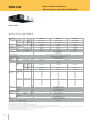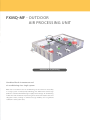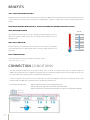
1
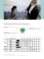
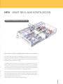
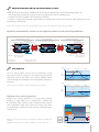
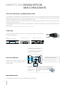
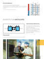
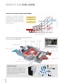
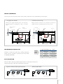
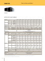
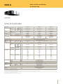
your comfort. our world. Ventilation Catalogue Heating Ventilation Integrated Solutions Air Conditioning Refrigeration Daikin Europe N.V. ABOUT DAIKIN Daikin has a worldwide reputation based on almost 85 years’ experience in the successful manufacture of high quality air conditioning equipment for industrial, commercial and residential use. Daikin quality Daikin’s much envied quality quite simply stems from the close attention paid to design, production and testing as well as aftersales support. To this end, every component is carefully selected and rigorously tested to verify its contribution to product quality and reliability. ENVIRONMENTAL AWARENESS Air Conditioning and the Environment Air conditioning systems provide a significant level of indoor comfort, making optimum working and living conditions possible in the most extreme climates. In recent years, motivated by a global awareness of the need to reduce the burdens on the environment, Daikin has invested enormous efforts in limiting the negative effects associated with the production and the operation of air conditioners. Hence, models with energy saving features and improved eco-production techniques have seen the light of day, making a significant contribution to limit the impact on the environment. 2 This sign highlights features where Daikin has invested into technologies to reduce the impact of air conditioning on the environment. This sign can be found on pages: 8 - 9 - 31 HRV - Heat Reclaim Ventilation 7 4 High static pressure 5 Built-in drain pump 20 20 Benefits for building owners 8 Connenction conditions 20 1 Energy energy saving ventilation 2 Reduces the load on the air conditiong system 3 Free cooling 8 9 9 Specifications 21 accessories 21 User friendly control Systems 23 1 Interlock of the ventilation operation with the air conditioner operation 2 Super wiring System 23 23 Overview of control systems 24 1 Individual Control Systems 2 Centralised Control Systems 26 28 Benefits for design offices and consultants 10 1 2 3 4 5 Total solution concept Slim design High static pressure Wide range of units Wide operation range 10 10 10 10 10 Benefits for installers 11 1 Simple design and construction 2 Filter cleaning 3 High static pressure 11 11 11 Benefits for end users 12 1 Create a high quality indoor environment 2 Fresh up operation 3Low operation sound level 4 Individual control via HRV remote control 12 13 13 13 Specifications 14 VAM-FA VKM-GM VKM-G 14 15 16 accessories 17 FXMQ-MF – outdoor air processing unit 19 Benefits 20 1Pair application 2Multi application 36 36 1 100% fresh air intake possible 2Leaves maximum floor and wall space for Furniture, decoration and fittings 3 Wide operation range 20 Specifications 37 Options 47 20 20 ERQ (pair) AND VRV® Air Handling Applications 31 Benefits 31 1 2 3 4 31 32 34 35 High efficiency High comfort levels Easy design and installation Total solution concept Which system offers me the best solution? 32 1 I only need a connection to an air handling unit 2 I need an air handling unit and heating, and/or cooling 32 32 System overview 33 Control possibilities 34 Selection of air handling units 35 3 Which system offers me the best solution? With the advent of new building regulations, greater awareness of increasing energy costs and a responsibility towards environmental issues, modern commercial spaces are insulated better than ever. Double glazing, thicker roof insulation and draught excluders of course, help considerably towards reducing heating/cooling demand and burdens on the environment. The down-side however, is that these same commercial spaces have now become, in effect, sealed boxes with little or no replenishment of the air. Daikin offers a variety of solutions for the provision of fresh air ventilation to offices, hotels, stores and other commercial outlets – each one complementary to and as flexible as both Sky Air® and VRV® systems themselves. Heat Reclaim Ventilation Proper ventilation is a key component of climate control in buildings, offices and shops. In its basic function, it ensures a flow of incoming fresh air and outgoing stale air. Our HRV (heat reclaim ventilation) solution can do much more. It can OPTIMISE THE BALANCE BETWEEN INDOOR AND OUTDOOR TEMPERATURE AND HUMIDITY , thus reducing the load on the system and increasing efficiency. recover heat and Outdoor Air Processing in a single unit COMBINE FRESH AIR TREATMENT AND AIR CONDITIONING IN A SINGLE SYSTEM , thereby eliminating Our FXMQ-MF air processing solution uses heat pump technology to the usual design problems associated with balancing air supply and discharge. Total system cost is reduced and design flexibility enhanced because the indoor air conditioning fan coil units and an outdoor air treatment unit can be connected to the same refrigerant line. erq (pair) and VRV® air handling applications For small, medium and large commercial spaces, we offer a range of R-410A inverter condensing units that provide air handling and air conditioning. This approach combines the flexibility of our ERQ and VRV® units with Air Handling Applications, OPTIMUM CONTROL OF INDOOR AIR QUALITY AND MAXIMUM EFFICIENCY. resulting in a simple, reliable design for overview ventilation range Ventilation: provision of fresh air 2 1 3 Air processing: optimise the balance between indoor and outdoor fresh air temperature Type name VAM-FA Components of indoor air quality 1 2 Humidification: optimise the balance between indoor and outdoor humidity Air flow rate (m3/h) 0 200 400 600 1 Ventilation 3 Heat Reclaim Ventilation VKM-G VKM-GM FXMQ-MF ERQ AND VRV® AIR HANDLING APPLICATIONS 2 EKEXV-kit 2 1 1 Ventilation 3 Air processing 3 2 1 Ventilation 2 Humidification 3 3 Air processing 2 1 OUTDOOR AIR PROCESSING UNIT 1 1 2 1 2 1 3 1 Ventilation 3 Air processing 3 1 Ventilation 3 Air processing Not connectable to VRV®III-S (RXYSQ-PAV, RXYSQ-PAY) Air flow rate is a calculated indication only, based on the following values: heating capacity EKEXV-kit * 200m³/h 800 1,000 1,500 2,000 4,000 6,000 8,000 6 HRV - Heat reclaim ventilation Ventilation, humidification & air processing HRV helps to create a high quality indoor environment The Daikin HRV (Heat Reclaim Ventilation) unit recovers heat energy lost through ventilation and maintains a comfortable and clean indoor environment without changes in room temperature. This also reduces the load on the air conditioning system and saves energy. In addition, the HRV interlocks with Daikin’s air conditioning systems (for example VRV® and Sky Air®) and automatically switches over to ventilation mode when needed, further increasing the effects of energy conservation. HRV can be integrated on the air conditioner remote control allowing total control over air conditioning and ventilation via a simple configuration. The current line-up includes models with or without DX coil and/or humidifier. The DX coil helps to prevent the direct impact of cold airflow upon persons during the heating cycle and vice versa, the humidifier optimises the balance between indoor and outdoor humidity. Finally high static pressure enhances design flexibility. 7 benefits for building owners Energy saving ventilation Buildings need year round ventilation. In traditional ventilation systems the conditioned inside air is lost when exhausted externally and new unconditioned air is brought into the building. This results in large amounts of air being heated up or cooled down over and above the actual load of the air conditioning system and leads to a substantial waste of energy. The Daikin HRV system however, automatically balances outside and inside temperature and humidity enabling the recovery of heat/cold with significant savings in running costs. Specially developed HEP element The heat exchange element uses a high efficiency paper (HEP) possessing superior moisture absorption and humidifying properties. The heat exchange unit rapidly recovers heat contained in latent heat (vapour). The element is made of a material with flame resistant properties and is treated with an anti-moulding agent. Operation of the high effiency paper. Outdoor 30.6°C 62% RH Indoor SA 27.4°C 63% RH Temperature and humidity 32°C 70% RH RA 26°C 50% RH Integrally-formed liner RH: Relative Humidity 8 SA: Supply Air (to room) RA: Return Air (from room) SA Integrallyformed liner RA Reducing the load on the air conditioning system Thanks to the use of heat reclaim ventilation the load on the air conditioning is reduced with approximately 31%. - 23% by operating in total heat exchange mode (in comparison with normal ventilation fans) - another 6 % by auto-ventilation mode changeover switching - a further 2 % by pre-cool, pre-heat control (reduces air conditioning load by not running the HRV shortly after the air conditioning is switched on.) Note: the values mentioned above may vary according to weather and other environmental conditions at the location of the unit’s installation Operation automatically switches to the optimum pattern to suit prevailing conditions Air conditioning in cooling Heat exchanger Exhaust fan Damper element (heat recovery) Air conditioning in heating Heat exchanger element (heat recovery) Air conditioning off In between (bypass ventilation) EA RA EA RA OA SA OA SA Automatic changeover Air supply fan RA EA Automatic changeover SA OA DX coil (heating) DX coil (cooling) Example: Outdoor temp. -5°C Indoor temp. 22°C Example: Outdoor temp. 30°C Indoor temp. 22°C EA: exhaust air OA: outdoor air Humidifying RA: return air (from room) SA: supply air (to room) Temp. °C Free cooling Morning Day time Night 26 The free cooling option reduces the air conditioning energy consumption and uses energy in a more efficient way by actively introducing fresh air into rooms. Free cooling maintains indoor comfort through the introduction of low temperature outdoor air into rooms. Set 21 temp. Outdoor temp. 16 Free cooling possible Free cooling possible Example of free cooling during summer Temp. °C Note: Free cooling is only available in combination with Intelligent Touch Controller Morning Day time Set 21 temp. 19 Outdoor temp. 16 Nighttime free cooling operation Night 100% free cooling possible Example of free cooling during intermediate season Nighttime free cooling operation is an energy saving function operating at night when the air conditioning is switched off. By ventilating rooms containing office equipment that increases room temperature, night purge reduces the cooling load when air conditioning is switched on in the morning, reducing the daily running costs. Temp. 40 30 20 Outdoor Temp. Setting Temp. Indoor Temp. 2 Hours auto start VKM Nighttime free cooling operation is factory set to “off” but can be activated by your Daikin dealer on request. Nighttime free cooling operation only available on VKM units connected to a VRV® system on off on Air Conditioner off start 9 benefits for design offices and consultants Total solution concept - integrated ventilation The integration of ventilation into a total building climate system, such as the VRV® system, offers numerous advantages. Daikin supplies software which simulates the working of the entire system, simplifying its design and presenting an ideal solution for the building itself and a ‘one-stop’ solution for the client. As well as design benefits, it also simplifies project follow-up, installation and subsequent commissioning and maintenance since only one party is involved. Finally, the end user benefits from ‘interlocking’ ventilation with air conditioner operation by virtue of greatly simplified overall system control. Note: more information on integrated control can be found in the control systems chapter Slim Design The slim design of the HRV unit enables it to be mounted in narrow ceiling voids and irregularly shaped spaces. Installation under the floor of a small building Installation under a beam 285mm VAM250FA Installation in an irregular space Higher static pressure and reduced noise The use of multiple, overlapping arc shaped fan blades makes it possible to optimize the chord lenght and blade outlet angle. High Static Pressure Rotating currents for reduced loss The use of a thinner scroll allows rectification of rotating currents within the scroll. External static pressure (ESP) up to 160 Pa facilitates the use with flexible ducts of varying lengths. Higher static pressure Thanks to wide fan diameter and optimized blade width Wide range of units The wide Daikin unit range ensures correct equipment design and sizing. 10 Higher static pressure and reduced pressure loss α In addition to increasing the scroll wrap angle and boosting the static pressure, the outflow angle has been optimized. θ Wide operation range VAM Cooling 50°CDB 50° The HRV unit can be installed in practically any location. The standard operation range (outdoor temperature) is from -15°C to 40°CDB (50°CDB for VAM units) and can be extended down to -25°C if a pre heater is installed. 1 VKM Cooling 40°CDB 40° 30° 20° 10° Contact your local dealer for more information and restrictions -20° -30° -15° CDB -25°CDB -15° CDB with optional preheater -10° with optional preheater 0° -25°CDB benefits for installers Simple Design and Construction Switch box Access door Upside down installation Horizontal installation Maintenance cover The unit can be installed either horizontally or upside down always allowing easy access for inspection and maintenance. A 450 mm square inspection hatch enables maintenance and heat exchange element replacement to be performed with ease. Also no drain connection is needed, further simplifying the installation. Filter Cleaning A signal on the remote control indicates when the air filter needs cleaning. 11 benefits for end users Creating a high quality indoor environment 100 Heating and cooling 80 60 + Heat recovery + Effect of full heat exchange Humidifying Outdoor air temperature in summer Effect of cooling 40 Indoor temperature during cooling Effect of humidification 20 Indoor temperature during heating Outdoor air temperature in winter Relative humidity (%) In addition to the HEP high efficiency paper, VKM models contain a DX-coil and humidifier (VKM only), thereby balancing the incoming fresh air with indoor temperature and humidity and ensuring the best possible indoor environment. Effect Effectofofheating heating Effect fullheat heat exchange exchange Effect ofof full -5 0 5 10 15 20 25 30 35 40 Dry bulb temperature (°CDB) Operation of humidicicaton and air processing in heating mode (VKM-GM) Exhaust Fan EA (Exhaust air to outdours) Heat Exchanger Elements Damper Motor Damper DX coil (Direct expansion coil) OA (Fresh air from outdoors) RA (Return air from room) SA (Supply air to room) Air Supply Fan Electronics Box (Control box) Float switch Humidifier element: Utilizing the principle of capillary action, water is permeated throughout the humidifier element. The heated air from the DX coil passes through the humidifier and absorbs the moisture. water AIRFLOW Drain pan 12 Solenoid valve SA Drain Fresh-Up Operation The user can select 2 fresh-up modes via the remote control for a more comfortable air environment. 1. Supply rich mode: 2. Exhaust fresh-up: Raising the air supply maintains proper room pressure to prevent back-flow of toilet/kitchen odours or moisture inflow. Raising exhaust air decreases room pressure to prevent the leaking of odours or floating bacteria into other rooms. Portion of fresh-up Normal operation HRV Air exhaust Air exhaust ventilation fan Air supply HRV Floor area Air supply Portion of Sick room exhaust operation eg. Office eg. Hospital low operation sound level Continues research by Daikin into reducing operation sound levels has resulted in sound pressure levels down to 20.5dBA (VAM150FA) Daikin indoor units dBA Perceived loudness Sound 0 20 Treshold of hearing Extremely soft Rustling leaves 40 60 80 100 120 Very soft Moderately loud Very loud Extremely loud Threshold of feeling Quiet room Normal conversation City traffic noise Symphonic orchestra Jet taking off Dust Prevention When the HRV is operating independently, the fan in an interlocked indoor unit continues turning, so dust does not fall from the air filter. Systems without dust prevention OFF Dust With Daikin HRV Blowing mode No dust is blown out 13 VAM-FA Heat reclaim ventilation VAM800FA SPECIFICATIONS INDOOR UNIT Power input - 50Hz Heat exchange Nom. mode Bypass mode Nom. Power input - 60Hz Heat exchange Nom. mode Bypass mode Nom. Temperature exchange efficieny - 50Hz Temperature exchange efficieny - 60Hz Enthalpy exchange efficieny - 50Hz kW kW kW % Ultra high/High/Low % Heat exchange system Heat exchange element Casing Material Dimensions Unit Weight Unit Fan Type Air flow rate 50Hz Air flow rate 60Hz Ultra high/High/Low Ultra high/High/Low Ultra high/High/Low Ultra high/High/Low % % % % HeightxWidthxDepth mm kg Heat Ultra high/ exchange High/Low mode Bypass Ultra high/ mode High/Low Heat Ultra high/ exchange High/Low mode Bypass Ultra high/ mode High/Low Ultra high/High/Low m³/h m³/h m³/h m³/h External static Pa pressure - 50Hz External static Ultra high/High/Low Pa pressure - 60Hz Heat exchange Ultra high/High/Low dBA mode Bypass mode Ultra high/High/Low dBA Heat exchange Ultra high/High/Low mode Bypass mode Ultra high/High/Low Operation range Min. Max. Relative humidity Connection duct diameter Piping connections Drain Insulation material Air filter Power supply Phase/Frequency/Voltage Sound pressure level - 60Hz kW Ultra high/High/Low Cooling Heating Enthalpy exchange Cooling efficieny - 60Hz Heating Operation mode Sound pressure level - 50Hz VAM150FA Ultra high/ High/Low Ultra high/ High/Low Ultra high/ High/Low Ultra high/ High/Low dBA dBA °CDB °CDB % mm Hz/V VAM250FA VAM350FA VAM500FA VAM650FA VAM800FA VAM1000FA VAM1500FA VAM2000FA 0.116/0.100/0.056 0.141/0.112/0.062 0.194/0.175/0.111 0.212/0.189/0.118 0.380/0.325/0.227 0.451/0.400/0.346 0.469/0.432/0.349 0.864/0.758/0.655 0.953/0.767/0.653 0.116/0.100/0.056 0.141/0.112/0.062 0.194/0.175/0.111 0.212/0.189/0.118 0.380/0.325/0.227 0.451/0.400/0.346 0.469/0.432/0.349 0.864/0.758/0.655 0.953/0.767/0.653 0.117/0.099/0.056 0.138/0.119/0.062 0.226/0.214/0.120 0.253/0.232/0.125 0.432/0.384/0.251 0.514/0.471/0.408 0.571/0.537/0.419 0.981/0.929/0.754 1.017/1.021/0.779 0.117/0.099/0.056 0.138/0.119/0.062 0.226/0.214/0.120 0.253/0.232/0.125 0.432/0.384/0.251 0.514/0.471/0.408 0.571/0.537/0.419 0.981/0.929/0.754 1.017/1.021/0.779 74/74/79 72/72/77 75/75/80 74/74/80 72/72/77 75/75/81 58/58/64 64/64/69 58/58/66 64/64/71 58/58/62 64/64/68 58/58/63 64/64/69 61/61/67 65/65/70 61/61/68 65/65/71 74/74/77 74/74/78.5 74/74/78 74/74/76 75/75/76.5 74/74/76 75/75/78 58/58/63 60/60/62 61/61/63 61/61/64 61/61/66 62/62/67 63/63/66 65/65/67 66/66/68 66/66/70 58/58/65 60/60/63 61/61/66 61/61/64 61/61/66 62/62/68.5 63/63/68 65/65/68 66/66/71 66/66/68 66/66/70 Heat exchange mode Bypass mode Fresh-up mode Air to air cross flow total heat (sensible + latent heat) exchange Specially processed non-flammable paper Galvanised steel plate 301x828x816 364x1,004x868 364x1,004x1,156 726x1,514x868 726x1,514x1,156 33 48 61 132 158 Sirocco fan 285x776x525 24 150/150/110 250/250/155 350/350/230 500/500/350 650/650/500 800/800/670 1,000/1,000/870 1,500/1,500/1,200 2,000/2,000/1,400 150/150/110 250/250/155 350/350/230 500/500/350 650/650/500 800/800/670 1,000/1,000/870 1,500/1,500/1,200 2,000/2,000/1,400 150/150/110 250/250/145 350/350/210 500/500/300 650/650/440 800/800/660 1,000/1,000/800 1,500/1,500/1,200 2,000/2,000/1,400 150/150/110 250/250/145 350/350/210 500/500/300 650/650/440 800/800/660 1,000/1,000/800 1,500/1,500/1,200 2,000/2,000/1,400 69/39/20 64/39/20 98/70/25 98/54/25 93/39/25 137/98/49 157/98/78 137/98/49 137/78/59 98/54/24 98/54/20 142/85/15 147/54/20 162/69/34 225/118/69 196/108/69 206/118/69 196/88/69 27 28.5/26 27.5/20.5 21.5 27 28.5/26.5 27.5/20.5 21.5 28 29/26 27/21 22 28 29/27 28/21 22 32 34/31.5 33/23.5 26 32 34/31 32.5/24.5 26.5 33 34.5/31.5 33/24.5 26.5 33.5 34.5/32.5 33.5/25.5 27.5 34.5 35.5/33 34/27 28 34.5 35.5/34 35/27 28.5 36 37/34.5 36/31 32 36 37/34.5 36/31 33 36 37/35 36/31 32 36 37/35.5 36/31 32 39.5 41.5/38 39/34 36 40.5 41.5/38 39/33.5 36 40 42.5/38 41/35 37 40 42.5/38 41/35 37 34.5/32/22 34/31/24 36/33/27 37/35/30 40.5/38/33 41/38/35 34.5/33/22 35/33/24 35.5/34/27 37/35/31 -15 50 80% or less 200 250 Self-extinguishable urethane foam Multidirectional fibrous fleeces 1~/50/60/220-240/220 40.5/38/33 41/38/35 28.5/26.5/19 29.5/26/19.5 28/27/20 100 29/27/20.5 150 (1) Air flow rate can be changed to Low mode or High mode. (2) Operation sound is measured at 1.5m below the center of the body. (3) Sound values are measured in an anechoic chamber. Operating sound level generally becomes higher than this value depending on the operating conditions, reflected sound, and peripheral noise. (4) The noise level at the air discharge port is about 8dB higher than the operating sound of the unit. 14 75/75/78 350 VKM-G Heat reclaim ventilation, air processing VKM80-100G SPECIFICATIONS INDOOR UNIT Power input - 50Hz Heat exchange mode Bypass mode Nom. Nom. Ultra high/ kW High/Low Ultra high/ kW High/Low kW kW % Fresh air Cooling conditioning load Heating Temperature exchange Ultra high/High/Low efficieny - 50Hz Ultra high/High/Low % Enthalpy exchange Cooling efficieny - 50Hz Ultra high/High/Low % Heating Operation mode Heat exchange system Heat exchange element Casing Material Dimensions Unit Weight Unit Fan Type Air flow rate 50Hz Sound pressure level - 50Hz Heat Ultra high/ exchange High/Low mode Bypass Ultra high/ High/Low mode External static Ultra high/High/ pressure - 50Hz Low Heat exchange Ultra high/High/ mode Low Bypass mode Operation range HeightxWidthxDepth Ultra high/High/ Low Around unit Supply air Return air Refrigerant Control Connection duct diameter Piping Liquid Type/OD connections Gas Type/OD Drain Insulation material Air filter Power supply Phase/Frequency/Voltage mm kg m³/h m³/h Pa dBA dBA VKM50G VKM80G VKM100G 0.560/0.490/0.420 0.620/0.560/0.470 0.670/0.570/0.480 0.560/0.490/0.420 0.620/0.560/0.470 0.670/0.570/0.480 4.71 (2) 5.58 (3) 7.46 (2) 8.79 (3) 9.12 (2) 10.69 (3) 78/78/79 74/74/76.5 76/76/77.5 64/64/67 67/67/69 Heat exchange mode Bypass mode Fresh-up mode 387x1,764x832 96 500/500/440 750/750/640 950/950/820 500/500/440 750/750/640 950/950/820 180/150/110 170/120/80 150/100/70 38 38.5 39/36 36.5 37/33.5 34.5 35.5 38 38.5 39/36 36.5 37/33.5 34.5 35.5 40 41 41.5/37.5 38 39/34.5 36 37 40 41 41.5/37.5 38 39/34.5 36 37 0°C~40°CDB, 80% RH or less -15°C~40°CDB, 80% RH or less 0°C~40°CDB, 80% RH or less Electronic expansion valve 40 40.5 41/38 38.5 39/35 36 36.5 40 40.5 41/38 38.5 39/35 36 36.5 °CDB °CDB °CDB mm mm mm Hz/V 66/66/68 62/62/66 71/71/73 65/65/69 Heat exchange mode Heat exchange mode Bypass mode Bypass mode Fresh-up mode Fresh-up mode Air to air cross flow total heat (sensible + latent heat) exchange Specially processed non-flammable paper Galvanised steel plate 387x1,764x1,214 109 114 Sirocco fan 200 250 Flare connection/6.35 Flare connection/12.7 PT3/4 external thread Self-extinguishable urethane foam Multidirectional fibrous fleeces 1~/50/220-240 (1) Cooling: indoor temp. 27°CDB, 19°CWB; outdoor temp. 35°CDB (2) Heating: indoor temp. 20°CDB; outdoor temp. 7°CDB, 6°CWB (3) Operation sound measured at 1.5m below the center of the unit is converted to that measured in an anechoic chamber, built in accordance with JIS C1502 condition. (4) The sound level at the air discharge port is about 8-11dB higher than operating sound of the unit. For operation in a quiet room, it is required to take measures to lower the sound, for example install more than 2m soft duct near the air discharge grille. (5) Air flow rate can be changed to Low mode or High mode. (6) Normal amplitude, input and efficiency depend on the mentioned conditions. 15 VKM-GM Heat reclaim ventilati on and air processing and humidification VKM80-100GM SPECIFICATIONS INDOOR UNIT Power input - 50Hz Heat exchange mode Bypass mode Nom. Nom. Ultra high/ kW High/Low Ultra high/ kW High/Low kW kW % Fresh air Cooling conditioning load Heating Temperature exchange Ultra high/High/Low efficieny - 50Hz Ultra high/High/Low % Enthalpy exchange Cooling efficieny - 50Hz Ultra high/High/Low % Heating Operation mode Heat exchange system Heat exchange element Humidifier System Material Casing Dimensions Unit Weight Unit Fan Type Air flow rate 50Hz Sound pressure level - 50Hz mm kg Heat Ultra high/ m³/h exchange High/Low mode Bypass Ultra high/ m³/h High/Low mode Ultra high/High/Low Pa External static pressure - 50Hz Heat exchange Ultra high/High/Low dBA mode Bypass mode Operation range HeightxWidthxDepth Ultra high/High/Low dBA Around unit Supply air Return air Refrigerant Control Connection duct diameter Piping Liquid Type/OD connections Type/OD Gas Water supply Drain Insulation material Air filter Power supply Phase/Frequency/Voltage VKM50GM VKM80GM VKM100GM 0.560/0.490/0.420 0.620/0.560/0.470 0.670/0.570/0.480 0.560/0.490/0.420 0.620/0.560/0.470 0.670/0.570/0.480 4.71 (2) 5.58 (3) 7.46 (2) 8.79 (3) 9.12 (2) 10.69 (3) 76/76/77.5 78/78/79 74/74/76.5 64/64/67 67/67/69 66/66/68 71/71/73 Heat exchange mode Bypass mode Fresh-up mode Air to air cross flow total heat (sensible + latent heat) exchange Specially processed non-flammable paper Natural evaporating type Galvanised steel plate 387x1,764x1,214 120 Sirocco fan 62/62/66 65/65/69 500/500/440 750/750/640 950/950/820 500/500/440 750/750/640 950/950/820 160/120/100 140/90/70 110/70/60 37 37.5 38/35 35.5 36/32 33 34 37 37.5 38/35 35.5 36/32 33 34 38.5 39 40/36 37 37.5/33 34 35.5 38.5 39 40/36 37 37.5/33 34 35.5 0°C~40°CDB, 80% RH or less -15°C~40°CDB, 80% RH or less 0°C~40°CDB, 80% RH or less Electronic expansion valve 39 39.5 40/37 37.5 38/34 34.5 35.5 39 39.5 40/37 37.5 38/34 34.5 35.5 387x1,764x832 102 °CDB °CDB °CDB mm mm mm mm Hz/V 200 125 250 Flare connection/6.35 Flare connection/12.7 6.4 PT3/4 external thread Self-extinguishable urethane foam Multidirectional fibrous fleeces 1~/50/220-240 (1) Cooling: indoor temp. 27°CDB, 19.0°CWB; outdoor temp. 35°CDB (2) Heating: indoor temp. 20°CDB; outdoor temp. 7°CDB, 6°CWB (3) Humidifying capacity: indoor temp. 20°CDB, 15°CWB; outdoor temperarure 7°CDB, 6°CWB (4) Operation sound measured at 1.5m below the center of the unit is converted to that measured in an anechoic chamber, built in accordance with JIS C1502 condition. (5) The sound level at the air discharge port is about 8-11dB higher than operating sound of the unit. For operation in a quiet room, it is required to take measures to lower the sound, for example install more than 2m soft duct near the air discharge grille. (6) For operation in a quiet room, it is required to take measures to lower the sound. For more details, refer to the data book (7) Air flow rate can be changed to Low mode or High mode. (8) Normal amplitude, input and efficiency depend on the mentioned conditions. 16 Accessories VAM-FA / VKM-GM / VKM-G PC board adapter wiring adapter for electrical appendices KRP2A61 for humidifier (running ON signal output) for heater control kit KRP50-2 BRP4A50 indoor unit FXFQ FXZQ FXCQ FXKQ FXDQ-M9 FXDQ-P FXSQ FXMQ- FXMQ-P7 MA for wiring reference installation box for adapter PCB - KRP1B571 KRP1B611 KRP1B61 KRP1B56 - - KRP1BA101 KRP4A96 KRPKRP1H98 KRP1B96 2/3 1BA101 6 FXAQ KRP1C64 4 KRP1B61 - 2/3 KRP4A93 2/3 FXUQ FXHQ KRP4A53 KRP1B3 FXLQ FXNQ KRP1B61 KRP1B97 KRP1C93 - 4 Notes: 1. Installation box is required 2. Up to 2 adapters can be fixed per installation box 3. Only 1 installation box can be installed per indoor unit 4. Up to 2 installation boxes can be installed per indoor unit 5. Installation box is necessary for second adapter 6. Option not available in combination with BYCQ140CGW1 Silencer Duct adapter 150 250 350 Replacement for air filter YAFF323F15 YAFF323F25 Replacement for air filter - - reference - nom. piping diameter - VAM-FA Duct adapter VKM-G(M) Silencer reference nom. piping diameter High efficiency filter Replacement for air filter 500 650 800 YAFF323F35 Ø 200mm Ø 200mm Ø 250mm - YAFM323F50 YAFM323F65 - - YAFF323F50 YAFF323F65 - YDFA25A1 - - - - - Ø 250mm 50 - - KAF241G80M KAF242G80M 1000 1500 2000 YAFM323F100 YAFM323F65 x 2 YAFM323F100 x 2 YAFF323F100 YAFF323F65 x 2 YAFF323F100 x 2 80 100 KDDM24B100 Ø 250mm KAF241G100M KAF242G100M 17 FXMQ-MF - Outdoor Air Processing Unit Ventilation & air processing Combined fresh air treatment and air conditioning via a single system Both fresh air treatment and air conditioning can be achieved successfully in a single system via heat pump technology. This without the usual design problems associated with balancing air supply and discharge. Air conditioning indoor units and an outdoor air processing units can be connected to the same refrigerant circuit, resulting in enhanced design flexibility and a significant reduction in total system costs. benefits 100% Fresh Air Intake Possible Outdoor air processing units can be used exclusively to provide 100% fresh air into the building. Even if only partly used the system reduces the load on the air conditioner by adjusting the outdoor air temperature via fixed discharge temperature control. Leaving maximum floor and wall space for Furniture, decoration and fittings Wide operation range FXMQ-MF The outdoor air processing unit can be installed practically anywhere. The unit operates at outdoor ambients up to 43°C in cooling mode and down to -5°C in heating mode. 50° High static pressure 20° 43°C 40° 30° 10° External static pressure (ESP) up to 225 Pa allows the use of extensive ductwork runs and facilitates the use with flexible ducts of varying lengths. Ideal for use in large areas. 0° -5°C -10° Built-in drain pump A drain pump kit increases the reliability of the drain system 1 1 Drain pump kit available as accessory Connection Conditions ›› The total connected capacity of the standard indoor units and fresh air treatment units must be between 50% and 100% of the capacity of the air conditioning outdoor units. The connected capacity of the fresh air treatment units must not exceed 30% of the capacity of the air conditioning outdoor units. ›› A fresh air treatment unit can also be used exclusively. The connected capacity of the fresh air treatment unit must be between 50% and 100% of the capacity of the air conditioning outdoor unit. ›› Connectable outdoor units: 20HP - VRV®III Heat pump Optimised for heating (RTSYQ-P) - VRV®III Heat pump High COP combination (RXYHQ16-36P8) - VRV®III Heat pump Small footprint combination (except 5HP unit) (RXYQ8-54P(A)(8)) VRV® III Series Outdoor Units Outdoor Air processing Unit Indoor Unit Indoor Unit 3x 5HP Indoor Unit Outdoor Air Processing unit 5HP Air Conditioning 20 Outdoor Air Supply FXMQ-MF Specifications 125, 200, 250 Outdoor air processing unit, ventilation and air processing FXMQ200-250MF SPECIFICATIONS cooling Capacity heating cooling Power Input heating Casing material Dimensions unit Weight unit Heat dimensions Exchanger Fan Piping connections kW kW kW kW height width depth nr of rows fin pitch face area nr of stages fin type fin type air flow rate cooling medium external static standard pressure model motor output (high) drive type liquid (OD) diameter type gas diameter drain diameter heat insulation mm mm mm kg mm m 2 m /min 3 Pa W mm mm mm Air Filter Refrigerant Refrigerant control Temperature control ›› ›› ›› ›› FXMQ200MF FXMQ250MF 14.0 8.9 0.359 0.359 Galvanised steel 470 744 1100 86 3 2.00 0.28 26 Cross fin coil Sirocco fan 18.0 22.4 13.9 0.548 0.548 28.00 17.40 0.638 0.638 470 1380 1100 123 3 2.00 0.65 26 Cross fin coil Sirocco fan 28.0 470 1380 1100 123 3 2.00 0.65 26 Cross fin coil Sirocco fan 35.0 185 225 205 D13/4G2DA1 380 Direct drive Flare connection 9.5 Flare connection 15.9 PS1B Glass fiber As option D13/4G2DA1 380 Direct drive Flare connection 9.5 Brazing/Brazing connection 19.1 PS1B Glass fiber As option R-410A Electronic expansion valve D13/4G2DA1 380 Direct drive Flare connection 9.5 Brazing/Brazing connection 22.2 PS1B Glass fiber As option Electronic expansion valve Microprocessor thermostat for cooling and heating Safety devices Safety devices Power Supply FXMQ125MF frequency Hz Fuse Fan motor thermal protector 50 voltage V 220-240 Electronic expansion valve Microprocessor thermostat for cooling and heating Microprocessor thermostat for cooling and heating Fuse Fan motor thermal protector 50 Fuse Fan motor thermal protector 50 220-240 220-240 Nominal cooling capacities are based on : outdoor temperature : 33°CDB, 28°CWB (68%RH), discharge set temperature : 18°CDB, equivalent piping length 7.5m (horizontal) Nominal heating capacities are based on : outdoor temperature : 0°CDB, -2.9°CWB (50%RH), discharge set temperature : 25°CDB, equivalent piping length 7.5m (horizontal) Capacities are net, including a deduction for cooling (an addition for heating) for indoor fan motor heat. Air filter is not standard accessory, but please mount it in the duct system of the suction side. Select its colorimetric method(gravity method) 50% or more. ACCESSORIES FXMQ125MF DESCRIPTION Long-life replacement filter Filters High-efficiency filter Filter chamber 1 65% KAFJ372L140 KAFJ372L280 90% KAFJ373L140 KAFJ373L280 KDJ3705L140 KDJ3705L280 Adapter for wiring ›› ›› ›› ›› FXMQ250MF KAFJ371L280 Drain pump kit 1 FXMQ200MF KAFJ371L140 KDU30L250VE KRP1B61 Filter chamber has a suction-type flange. (Main unit does not). Dimensions and weight of the equipment may vary depending on the options used. Some options may not be usable due to the equipment installation conditions. Please confirm prior to ordering. Some options may not be used in combination. Operating sound may increase somewhat depending on the options used. 21 22 user friendly CONTROL SYSTEMS Interlock of the ventilation operation with the air conditioner operation Interlock of the ventilation operation with the air conditioner operation greatly simplifies overall system control. The same remote control centralizes air conditioning and ventilation operations, obviating any need for ventilation remote control installation work. Using a centralized remote control also frees the user to choose from a wide range of control systems that integrate air conditioning and ventilation. By incorporating a variety of centralized control equipment, the user can build a large, high grade centralized control system. Linked control of FXMQ-MF and HRV is not supported 1 VRV® indoor unit ›› ›› ›› ›› ›› ON/OFF signal Cooling/Heating mode signal Set temperature signal Ventilation signal Humidifier ON/OFF signal Interlocking ›› Operating mode signal ›› Filter cleaning signal ›› Faillure detection signal HRV “Super Wiring” System A Super Wiring system is used to enable the shared use of wiring between indoor units, outdoor units and the centralised remote control. This system makes it easy for the user to retrofit the existing system with a centralised remote control, simply by connecting it to the outdoor units. Thanks to a non polarity wiring system, incorrect connections become impossible and installation time is reduced. Indoor unit VKM Wired remote control Outdoor unit 23 Overview of control systems Individual Control Systems 5 individual control systems give the user control over the VRV® system and the combined ventilation. ›› BRC1D52 and BRC1E51A are wired remote controllers, giving access to room temperature settings, schedule timer, … Next to that they also have user friendly HRV functions. ›› BRC301B61 is a wired controller especially designed for VAM units. ›› BRC2C51 and BRC3A61 are compact, easy to use remote controllers, ideal for use in hotel bedrooms. VAM remote control BRC301B61 Wired remote control BRC1E51A Wired remote control BRC1D52 Centralised control systems By combining the (optional) centralised control equipment listed below, the user can achieve a wide range of comprehensive centralised control systems for air conditioning and ventilation. Centralised remote control DCS302C51 Unified ON/OFF control DCS301B51 Schedule timer DST301B51 Network solutions HRV and the Outdoor Air Processing unit are connectable to all current Daikin network solutions: Basic solution for control and management of up to 2,000 indoor units (Sky Air® and VRV®). Allows detailed and easy monitoring and operation of VRV® systems (maximum 2 x 64 control groups). The ideal solution for full control and management of maximum 1,024 VRV® indoor units. LonWorks Interface Open network integration of VRV® monitoring and control functions into LonWorks® networks. BACnet Interface Integrated control system for seamless connection between VRV® and BMS systems. For more information consult the Daikin controls systems brochure or contact your local dealer 24 DESCRIPTION VAM remote control HRV FXMQ-MF BRC301B611 BRC1D52 / BRC1E51A Wired air conditioner remote control Centralised remote control DCS302C51 Unified on/off control DCS301B51 Schedule timer DST301B51 DS net adapter DTA113B51 Intelligent touch controller DCS601C51 Intelligent Manager DAM602B51/B52 LonWorks interface DMS504B51 BACnet interface DMS502A51 Wiring adapter for electrical appendices (1) Wiring adapter for electrical appendices (2) KRP2A61 - KRP4A51 25 BRC1E51A BRC1D52 Individual Control Systems ›› ›› ›› ›› ›› ›› ›› ›› ›› ›› ›› ›› ›› Control up to 16 indoor units or 8 HRV units (1group) Easy to use: all main functions directly accessible Easy setup: improved graphical user interface for advanced menu settings Simultaneous ON/OFF of HRV and air conditioner (BRC1D52/BRC1E51A) Airflow rate switching (initial setting) Ventilation mode switching (initial setting) Self diagnostic functions Filter sign display and reset Timer settings, simultaneous control with air conditioner (BRC1D52/BRC1E51A) ON/OFF of VAM (BRC301B61) Independent operation of HRV Timer settings (BRC301B61) Fresh-up mode switching (HRV only) (Selectable: supply rich mode, exhaust rich mode; initial setting) Notes: The remote control wired to the FXMQ-MF cannot be set as master remote control. Otherwise, when set to ‘auto’, the operation mode will switch according to outdoor air conditions, regardless of indoor temperature. BRC301B61 26 A variety of units can be controlled using only the BRC1D52 or the BRC1E51A (HRV only) ›› Group Control One air conditioner remote control simultaneously controls up to 16 air conditioning and HRV units. ›› Control using 2 remote controls Allows control of air conditioning and HRV units from two locations by connecting two air conditioner remote controls. (group control is possible) ›› Long-distance Remote Control Remote operation control - from a distant control room for example - is possible thanks to wiring of up to 500 m. (2 remote controllers possible) Indoor units Long distance remote control Up to 500m HRV Control using 2 remote controls Up to 500m Group control BRC1E51A no2 BRC1E51A no1 *1: Count VKM unit as two air conditioner indoor units. For details, System Characteristics BRC1D52 BRC1E51A BRC301B61 BRC1D52 BRC1E51A BRC301B61 Standard system BRC1D52 or BRC1E51A or BRC301B61 During group control operation, the VKM unit has a capacity equivalent to 2 standard indoor units. Up to 16 standard indoor units can be connected at the same time. 2 12 3 10 4 8 5 6 6 4 7 2 8 0 ›› Multiple VRV® indoor units or HRV units can be connected and controlled in batches, with interlocked operation of HRV and air conditioners by using the air conditioner remote control. ›› The HRV unit can also be operated independently using the remote control for the indoor unit, even if the indoor unit is not in operation BRC1D52 or BRC1E51A Note: The VKM uses 2 remote controller addresses per unit. The number of units that can be group controlled is shown above. Group 1 Group 1 Operation system Multiple groups interlocked (VRV®, Sky Air®) system BRC1D52 BRC1E51A Connectable indoor units: VKM 0 1 16 14 Max. no. of VRV® Necessary Accessories HRV Indoor unit Air conditioning interlocked control ›› Independent operation of HRV is possible ›› Operation is possible using 2 remote controls ›› Multiple HRV units can be simultaneously controlled in batch. (Up to 8 HRV units can be connected) ›› Air conditioner remote control can be used HRV HRV Operation system Independent see below. System construction (hrv only) Group 2 Group 1 Indoor unit BRC1D52 BRC1E51A HRV Indoor unit BRC1D52 BRC1E51A BRC1D52 BRC1E51A KRP2A61 BRC301B61 only available for VAM-FA Indoor unit Group 2 Group 2 Indoor unit ›› Can control interlocked operation of multiple groups of VRV® or Sky Air® indoor units ›› When one of the multiple groups operates, HRV units are interlocked and operate simultaneously BRC1D52 or BRC1E51A BRC1D52 BRC1E51A HRV 27 Note: ›› Group control is not possible between FXMQ-MF and standard type indoor units. Connect remote controllers to each unit. ›› Not all FXMQ-MF functions are available when using centralised control. Please refer to your local installer for detailed information. ›› The remote control wired to the FXMQ-MF cannot be set as master remote control. Otherwise, when set to ‘auto’, the operation mode will switch according to outdoor air conditions, regardless of indoor temperature. ›› Temperature setting and PPD are not possible, even when Intelligent Touch Controller or Intelligent Manager are installed. Centralised Control Systems By combining the (optional) centralised control equipment listed below, the user can achieve a wide range of comprehensive centralised control systems for air conditioning and ventilation. Centralised remote control - DCS302C51 ›› ›› DCS302C51 ›› ›› ›› ›› ›› ›› ›› ›› DCS301B51 A maximum of 64 groups (128 indoor units, max. 10 outdoor units) can be controlled A maximum of 128 groups (128 indoor units, max. 10 outdoor units) can be controlled via 2 centralised remote controls in separate locations Group control (up and down buttons are added for group selection) Zone control Malfunction code display Max. wiring length 1,000 m (total : 2,000 m) Combination with unified ON/OFF control, schedule timer and BMS system Airflow volume and direction can be controlled individually for indoor units in each group operation. Ventilation volume and mode can be controlled for Heat Reclaim Ventilation (VKM). Up to 4 ‘operation/stop’ pairs can be set per day by connecting a schedule timer. Unified on/off control - DCS301B51 Providing simultaneous and individual control on 16 groups of indoor units ›› A maximum of 16 groups (128 air conditioning indoor and HRV units) can be controlled ›› 2 remote controls in separate locations can be used ›› Centralised control indication ›› Maximum wiring length of 1,000m (total: 2,000m) DST301B51 Schedule timer - DST301B51 Enabling 64 groups to be programmed ›› A maximum of 128 air conditioning indoor and HRV units can be controlled ›› 8 types of weekly schedule ›› A maximum of 48 hours back-up power supply ›› Maximum wiring length of 1,000m (total: 2,000m) Number of HRV units that can be connected per system 28 Centralised remote control 2 units Unified on/off control 8 units Schedule timer 1 unit SYSTEM CHARACTERISTICS SYSTEM CONSTRUCTION (HRV only) NECESSARY ACCESSORIES Unified on/off control DCS301B51 HRV Indoor unit BRC1D52 BRC1E51A DCS301B51 DST301B51 BRC1D52 BRC1E51A ›› Up to 8 controllers can be installed in one centralised transmission line (in one system), which enables control of up to 128 groups. (16 groups x 8 = 128 groups) Schedule timer - DST301B51 ›› One schedule timer can control the weekly sche-dule of up to 128 units Indoor unit ›› Control system can be expanded depending on its purposes by combining a variety of centralised control equipment BRC1D52 BRC1E51A Centralised Control System DCS301B51 or DST301B51, BRC1D52 or BRC1E51A If necessary: DCS302C51 ›› HRV remote control can set the individual operation of each HRV unit HRV Zone 1 Indoor unit DCS302C51 HRV BRC1D52 BRC1E51A BRC1D52 BRC1E51A air conditioners ›› The centralised remote control provides settings and monitoring functions and can control up to 128 VRV® and HRV units. A special adapter is required to connect Sky Air® to the centralised line. ›› Control is possible in 3 different patterns: individual, batch or zone ›› Multiple groups can be controlled within the same zone Zone 2 Zone Control System Centralised remote control DCS302C51 ›› Multiple HRV units can be operated independently Indoor unit HRV DCS302C51, BRC1D52 or BRC1E51A If necessary: DSC301B51 or DST301B51 ›› System without air condi-tioning or HRV remote controls can be constructed BRC1D52 BRC1E51A Combination with other types of Air Conditioning Interlocked Batch / Individual Control System ›› One controller can control the on/ off operation of 16 groups of units collectively or individually ›› Control system can be expanded depending on requirements by combining a variety of centralised control systems No-voltage a-contact signal Adapter HRV Air conditioner BRC1D52 BRC1E51A Connecting line can be extended up to 50m ›› Simultaneous operation of HRVs and air conditioners is possible via BRC1D52/ BRC1E51A ›› Use of the HRV remote control enables to change settings or operate HRVs independently Connection adapter (no-voltage-acontact-signal) 29 ERQ (pair) AND VRV ® AIR HANDLING APPLICATIONS For small to large commercial spaces Daikin offers a range of R-410A inverter condensing units for use in conjunction with air handling units. In situations where Daikin commercial range ventilation units cannot satisfy the ventilation requirement due to building constraints (large atriums, banquet halls etc), air handling units represent the ideal solution. Air handling units provide large fresh air volumes (> 1,000 m³/h) and high ESPs enabling the use of extensive ductwork runs. For more information on Daikin air handling units refer to the air handling unit catalogue. Benefits of ERQ and VRV® air handling applications Outside air = 10°C Fresh air supplied at 21°C. The temperature difference with the outdoor air is heated up for free by heat recovery via A/C system High efficiency Daikin heat pumps are renowned for their high energy efficiency with COPs up to 4.56 in heating1. The VRV® range offers both heat pump and heat recovery units with part load efficiencies as high as 9.02. Integrating the AHU with a heat recovery system is highly effective since an office system can frequently be in cooling mode while the outdoor air is too cold to be brought inside in an unconditioned state. In this case heat from the offices is merely transferred to heat up the cold incoming fresh air. In the absence of an AHU this ‘free heating’ the incoming fresh air would not be possible. 1 ERQ100AV1 heat pump 2 REYQ8P8 50% cooling – 50% heating load. Conditions: outdoor temperature 11°CDB, indoor temperature 18°CWB, 22°CDB Indoor temperature 22°C, needs cooling because of solar radiation. The excessive heat can be transferred to the AHU High comfort levels Daikin ERQ and VRV® units respond rapidly to fluctuations in supply air temperature, resulting in a steady indoor temperature and resultant high comfort levels for the end user. Easy design and installation The system is easy to design and install since no additional water systems such as boilers, tanks and gas connections etc are required. This also reduces the total system cost. Total solution concept Integrating an air handling unit into the total building climate system enables both design and installation procedures to based on a single common technology. This simplifies project follow-up, installation, commissioning and maintenance since only one party is involved. 31 which system offers me the best solution? In order to maximise combination potential, Daikin offers ‘pair’ and ‘multi’ combination plus several expansion kits and control systems. Control box and expansion valve kits are required for each combination with an air handling unit. Both option kits are designed for indoor and outdoor installation and can be wall mounted. I only need a connection to an air handling unit Outdoor unit combined with indoor units Expansion valve kit Air handling unit A solution for your shop, warehouse, showroom or office. Control box ERQ heat pump ›› ›› ›› ›› ›› ›› ERQ Inverter controlled units Large capacity range (from 100 to 250 class) Heat pump R-410A Flexible control possibilities Wide range of expansion valve kits available System Type Cooling capacity (kW) Heating capacity (kW) ERQ-AV1 Air-cooled ERQ-AW1 4 5 6 8 10 11.2 14.0 15.5 22.4 28.0 12.5 16.0 18.0 25.0 31.5 I need an air handling unit and heating, and/or cooling Air handling unit Control box Expansion valve kit VRV® Outdoor unit Integrate your air handling unit in a Total solution for your shop or office building. VRV® heat recovery / heat pump ›› Inverter controlled units ›› Integrates in all VRV® heat recovery and heat pump systems up to 54 HP ›› Provides virtually free heating for the air handling unit via recovered heat from indoor units in cooling1 ›› Control of air temperature via standard Daikin wired remote control ›› Large range of expansion valve kits available 1 2 In case of connection to a VRV® heat recovery outdoor unit For more information on VRV® units refer to the VRV® catalogue System Type Cooling capacity (kW) Heating capacity (kW) Heat recovery Air-cooled VRV® Heat pump Heat recovery Water-cooled VRV® Heat pump 32 4 5 6 8 VRV® Indoor unit connected to the same system 10 12 14 16 18 20 22 24 26 28 30 32 34 36 38 40 42 44 46 48 50 52 54 11.2 14.0 15.5 22.4 28.0 33.5 40.0 45.0 49.0 55.9 61.5 67.0 71.4 77.0 82.5 89.0 94.0 98.0 105.0 111.0 116.0 120.0 126.0 132.0 138.0 143.0 147.0 12.5 16.0 18.0 25.0 31.5 37.5 45.0 50.0 56.5 62.5 69.0 75.0 81.5 88.0 94.0 102.0 107.0 113.0 119.0 126.0 132.0 138.0 145.0 151.0 158.0 163.0 170.0 System overview Pair application: ERQ Air handling unit Expansion valve kit: EKEXV F1, F2 communication Control box: EKEQDCB: Control Z EKEQFCB: Control X,Y DDC controller (field supplied) Control X Multi application: VRV® Air handling unit EKEXV-kit Control box: EKEQMCB Control Z Daikin communication wire (F1, F2 communication) Other communication wire Liquid pipe Gas pipe 33 Control possibilities In order to maximise installation flexibility, 3 types of control systems are offered: Possibility X (Td/Tr control): Air temperature control via an external DDC controller (field supplied) Room temperature is controlled as a function of the air handling unit suction or discharge air (customer selection). The DDC controller is translating the temperature difference between set point and air suction temperature (or air discharge temperature or room temperature) into a reference voltage (0-10V) which is transferred to the Daikin control box (EKEQFCBA). This reference voltage will be used as the main input value for the compressor frequency control. Ts DDC Possibility Y (Te/Tc control): Daikin control box: EKEQFCB Set point can be fixed via standard Daikin wired remote controller. Remote ON/OFF can be achieved by an optional adapter KRP4A51. No external DDC controller should be connected. The cooling load is determined from the air suction temperature and set point on the Daikin controller. = Air suction temperature = Air discharge temperature = Room temperature KRP4A51 Ts Daikin control box: EKEQDCB EKEQMCB Te = Evaporating temperature AHU = Air Handling Unit DDC = Digital Display Controller Field supplied DDC controller is required Temperature control using air suction or air discharge temperature EKEQFCB fixed evaporating temperature, Possibility yUsing no set point can be set using remote controller Possibility z EKEQDCBUsing Daikin wired remote controller BRC1D52 or BRC1E51A EKEQMCB* Temperature control using air suction temperature * EKEQMCB (for ’multi’ application) 34 Room BRC1D52 BRC1E51A Option kitFeatures Possibility x Td ON / OFF Using Daikin wired remote controller (BRC1D52 or BRC1E51A - optional) Ts Td Tr Room Te AHU TR A fixed target evaporating temperature of between 3°C and 8°C can be set by the customer. In this case, room temperature is only indirectly controlled. The cooling load is determined from the actual evaporating temperature (i.e. load to the heat exchanger). A Daikin wired remote controller (BRC1D52 or BRC1E51A - optional) can be connected for error indication. Possibility Z (Td/Tr control): Td TR Ts By fixed evaporating temperature Te AHU Daikin control box: EKEQFCB Te Td AHU TR Room BRC1D52 BRC1E51A 35 Selection of air handling units Pair application Step 1: Select required capacity of AHU Based on the required capacity of the AHU please select the expansion valve Step 1 Allowed heat exchanger volume (dm ) Allowed heat exchanger capacity in coolong (kW) 3 Allowed heat exchanger capacity in heating (kW) EKEXV class Minimum Maximum Minimum Standard Maximum Minimum Standard 63 1.66 2.08 6.3 7.1 7.8 7.1 8.0 Maximum 8.8 80 2.09 2.64 7.9 9.0 9.9 8.9 10.0 11.1 100 2.65 3.3 10 11.2 12.3 11.2 12.5 13.8 125 3.31 4.12 12.4 14.0 15.4 13.9 16.0 17.3 140 4.13 4.62 15.5 16.0 17.6 17.4 18.0 19.8 200 4.63 6.6 17.7 22.4 24.6 19.9 25.0 27.7 250 6.61 8.25 24.7 28.0 30.8 27.8 31.5 34.7 Heat exchanger capacity is defined under following conditions: Saturated suction temperature (SST) = 6°C, Superheat (SH) = 5K Subcool condensor (SC) = 3K Air temperature = 27°CDB/19°CWB Eg: If you need 14kW in cooling, you will require an expansion valve of 125class (EKEXV125). The heat exchanger capacity has priority over the volume of the heat exchanger and is therefore the determining factor for the selection of the expansion valve. More information on the volume can be found in the data book and service manual. Step 2: Select outdoor unit Pair combinations with ERQ outdoor units are possible based on the same principle as standard DX units. The capacity of the AHU unit is indicated by the capacity of the expansion valve and can be connected as indicated in below table. Step 2 1~ ERQ 3~ Class 63 Class 80 Class 100 Class 125 Class 140 Class 200 Class 250 EKEXV63 EKEXV80 EKEXV100 EKEXV125 EKEXV140 EKEXV200 EKEXV250 x or y Control Expansion valve kit EKEQFCB EKEQDCB OUTDOOR UNIT Control z Control box ERQ100AV1 P P P P P P - - - ERQ125AV1 P P P P P P P - - ERQ140AV1 P P - P P P P - - ERQ125AW1 P P P P P P P - - ERQ200AW1 P P - - P P P P P ERQ250AW1 P P - - - P P P P P: Pair, combination depending on AHU coil volume and capacity Eg: Based on above selected expansion valve, the EKEXV125 has a capacity of class 125. Therefore we can choose to connect it in pair with all outdoor units indicated in the table above with P. Step 3: Control box selection Please make your selection of the control box based on your requirements. All the different control possibilities are mentioned on page 34. More information on the selection is available in the service manual. 36 Multi application Step 1: Select required capacity of AHU Based on the required capacity of the AHU please select the expansion valve Step 1 EKEXV class Allowed heat exchanger volume (dm3) Allowed heat exchanger capacity in cooling (kW) Allowed heat exchanger capacity in heating (kW) Minimum Maximum Minimum Standard Maximum Minimum Standard 50 0.76 1.65 5.0 5.6 6.2 5.6 6.3 7.0 63 1.66 2.08 6.3 7.1 7.8 7.1 8.0 8.8 80 2.09 2.64 7.9 9.0 9.9 8.9 10.0 11.1 100 2.65 3.3 10 11.2 12.3 11.2 12.5 13.8 6.9 Maximum 125 3.31 4.12 12.4 14.0 15.4 13.9 16.0 17.3 140 4.13 4.62 15.5 16.0 17.6 17.4 18.0 19.8 200 4.63 6.6 17.7 22.4 24.6 19.9 25.0 27.7 250 6.61 8.25 24.7 28.0 30.8 27.8 31.5 34.7 Eg: If the required capacity of the AHU is 6.9kW in cooling, which lies between 6.3 and 7.8, the EKEXV63 can be selected. The heat exchanger capacity has priority over the volume of the heat exchanger and is therefore the determining factor for the selection of the expansion valve. More information on the volume can be found in the data book and service manual. Step 2: Select outdoor unit Multiple AHU can be connected to a VRV® system and the connection principle is similar as for ERQ. Connection of the full system can be up till 110% including at least 1 Daikin indoor unit (cassette, duct, …) The capacity index of the AHU needs to be calculated based on the indicated capacity of the selected expansion valve and the actual capacity. The AHU capacity index = capacity class (expansion valve) * ratio (actual capacity AHU / standard capacity expansion valve) Eg: AHU has a capacity requirement of 6.9kW and the selected expansion valvue is the EKEXV63 with a standard capacity of 7.1kW. So the AHU capacity = 63 * (6.9kW / 7.1kW) = 61 class In case that in the system 2 FXSQ50 class are connected, the total sum of capacity would be 61 + 2*50 = 161 class Based on the 161 class a 10 HP is required as outdoor unit. 1 For detailed specifications of VRV® outdoor units, refer to the VRV® catalogue or databooks Step 3: Control box selection EKEQMCB is the control box which is required to control the communication between the AHU and the VRV® system beside the standard communication of the Daikin DX indoor units (cassette, duct, wall…). More information on the selection is available in the service manual. 37 ERQ Air handling application (pair) SPECIFICATIONS OUTDOOR UNIT ERQ100AV1 ERQ125AV1 ERQ140AV1 ERQ125AW1 ERQ200AW1 Capacity range HP 4 5 6 5 8 10 Cooling capacity Nom. kW 11.2 (1) 14.0 (1) 15.5 (1) 14.0 (1) 22.4 (1) 28.0 (1) kW 12.5 (2) 16.0 (2) 18.0 (2) 16.0 (2) 25.0 (2) 31.5 (2) Heating capacity Nom. Capacity control Power input Cooling Min./Max. % 24/100 Cooling Nom. kW - 3.52 (1) 5.22 (1) 7.42 (1) Heating Nom. kW - 4.00 (2) 5.56 (2) 100 7.70 (2) 3.42 (1) 3.98 (1) 4.29 (1) 3.77 (1) 3.94 (2) 4.00 (2) 4.50 (2) 4.09 (2) 3.99 (1) EER 4.56 (2) COP Casing Material Dimensions Unit Weight Unit 4.15 (2) Painted galvanized steel plate HeightxWidthxDepth mm kg Type Painted galvanized steel plate 1,345x900x320 1,680x635x765 120 159 m³/min m³/min 102 Sound power level Cooling Nom. dBA 66 67 69 72 Cooling Nom. dBA 50 51 53 54 Heating Nom. dBA 52 53 55 Sound pressure level Compressor Compressor 2 106 105 Model Type 240 Propeller Cooling Nom. Air flow rate 1,680x930x765 187 Propeller Heating Nom. Fan 95 171 95 171 185 185 78 57 58 - JT100G-VDL Inverter Hermetically sealed scroll compressor Hermetically sealed scroll compressor Model - - ON - OFF Type - - Hermetically sealed scroll Cooling Min.~ Max. °CDB -5~ 46 -5~ 43 Heating Min.~Max. °CWB -20~15.5 -20~15 Enterning air Cooling temperature on AHU Heating heat exchanger Type Min.~ Max. °CDB -14CWB~25CWB 35°CDB Min.~Max. °CWB 10CWB~27CWB 10CWB~27CWB Operation range Refrigerant R-410A Charge kg Piping connections l Type/OD Gas Type/OD mm Drain Quantity/OD mm Piping length Max. m OU - IU Phase/Frequency/Voltage 1.7 Flare connection/9.52 Flare connection/15.9 Hz/V 8.4 Synthetic (ether) oil 1.5 mm 7.7 Electronic expansion valve Daphne FVC68D Charged volume Heat insulation Power supply 6.2 Expansion valve (electronic type) Type Liquid R-410A 4.0 Control Refrigerant oil ERQ250AW1 2.1 4.3 Braze connection/9.52 Braze connection/19.1 Braze connection/15.9 Braze connection/19.1 Braze connection/22.2 3/26x3 - 55 55 Both liquid and gas pipes Both liquid and gas pipes 1N~/50/220-440 3N~/50/400 (1) Cooling: indoor temp. 27°CDB, 19°CWB; outdoor temp. 35°CDB; equivalent piping length: 7.5m (horizontal); level difference: 0m (2) Heating: indoor temp. 20°CDB; outdoor temp. 7°CDB, 6°CWB; equivalent refrigerant piping: 7.5m; level difference: 0m (3) Sound pressure level is a relative value, depending on the distance and acoustic environment. For more details, please refer to the sound level drawings. (4) Sound values are measured in a semi-anechoic room. (5) Sound pressure level is a relative value, depending on the distance and acoustic environment. For more details, please refer to the sound level drawings. EKEXV Indoor unit Casing Dimensions Weight Sound pressure level Operation range Control box EKEXV50 Material Unit Unit Nom. Cooling HeightxWidthxDepth Min.~ Max. mm kg dBA °CDB EKEXV63 EKEXV80 EKEXV100 EKEXV125 Metal 401x215x78 2.9 EKEXV140 EKEXV200 EKEXV250 45 -5.0~ 46.0 (1)The sound pressure value is the maximum value measured at 10cm from the motor.(2)Minimum and maximum piping length refer to the piping between the expansion valve kit (EKEXV) and the air handling unit(3)Equivalent piping length: refer to the capacity connection ratio of the outdoor unit; depends on outdoor unit(4)Maximum installation height difference: See manual; depends on outdoor unit 38 your comfort. our world. FSC Carbon Balanced Paper Visit www.eca.gov.uk/etl and type ‘Daikin’ in the quick search box for details of the latest ECA qualifying Daikin units Daikin units comply with the European regulations that guarantee the safety of the product. The present catalogue is drawn up by way of information only and does Daikin products are distributed by: not constitute an offer binding upon Daikin UK. Daikin UK has compiled the content of this catalogue to the best of its knowledge. No express or implied warranty is given for the completeness, accuracy, reliability or fitness for particular purpose of its content and the products and services presented therein. Specifications are subject to change without prior notice. Daikin UK explicitly rejects any liability for any direct or indirect damage, in the broadest sense, arising from or related to the use and/or interpretation of this catalogue. All content is copyrighted by Daikin UK. Daikin Airconditioning UK Limited The Heights Brooklands Weybridge Surrey KT13 0NY Tel 0845 6419000 Fax 0845 6419009 www.daikin.co.uk Scotland Region Northern Region Midlands Region Western Region North London South London 0845 641 9330 0845 641 9340 0845 641 9370 0845 641 9320 0845 641 9360 0845 641 9355 UKEPCEN12-*** / 03.12 / Shere Marketing. Copyright 2012 Daikin Printed in the UK on FSC certified paper from sustainable sources. Daikin Europe N.V. participates in the Eurovent Certification Programme for Air Conditioners (AC), Liquid Chilling Packages (LCP) and Fan Coil Units (FC); the certified data of certified models are listed in the Eurovent Directory. Multi units are Eurovent certified for combinations up to 2 indoor units. VRV products, Rooftops, FWB-J and FWD-units are not within the scope of the Eurovent Certification Programme.