1
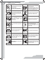
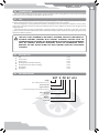
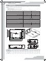
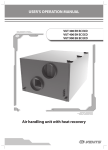
USER’S MANUAL VUT 160 PB EC A14 VUT 350 PB EC A14 HEAT RECOVERY AIR HANDLING UNIT 2 CONTENTS Safety requirements Introduction Use Delivery set Designation key Technical data Unit design and operating logic Mounting and set-up Condensate drainage Connection to power mains Unit control Maintenance Fault handling Storage and transportation rules Manufacturer's warranty Acceptance certificate 3 5 5 5 5 6 7 9 11 12 13 14 15 16 16 17 Seller information 17 Connection certificate Warranty card 17 17 3 SAFETY REQUIREMENTS • Read the user’s manual carefully prior to the operation and installation of the VUT PB EC A14 heat recovery air handling unit. • Fulfil the operation manual requirements as well as the provisions of all the applicable local and national construction, electrical and technical codes and standards. • The warnings contained in the user’s manual must be considered most seriously since they contain vital personal safety information. • Failure to follow the safety requirements may result in an injury or unit damage. • Read the manual carefully and keep it as long as you use the unit. • While transferring the unit control the user’s manual must be turned over to the receiving operator. Symbol legend used in the manual: WARNING! DO NOT! UNIT MOUNTING AND OPERATION SAFETY PRECAUTIONS The unit must be disconnected from power supply prior to any installation or repair operations. The unit must be grounded! The unit must not be operated outside the temperature range stated in the user’s manual and in aggressive or explosive environments. Do not use damaged equipment or conductors to connect the unit to power mains. While installing the unit follow the safety regulations specific to the use of electric tools. Unpack the unit with care. Do not change the power cable length at your own discretion. Do not bend the power cable. Avoid damaging of the power cable. Do not position any heating devices or other equipment in close proximity to the unit power cable. 4 Do not touch the unit controls with wet hands. Do not carry out the unit maintenance with wet hands. Use the unit only as intended by the manufacturer. Do not connect a clothes dryer or other similar equipment to the unit or the ventilation system. Do not wash the unit with water. Protect the unit electric parts from water ingress. Do not put any water containers on the unit, i.e. flower vases. Keep combustible gases and inflammable products away from the unit. ON OFF Disconnect the unit from power supply prior to maintenance. Do not let children operate the unit. Do not damage the power cable while operating the unit. Do not put any objects on the power cable. Do not sit on the unit and do not put any objects on it. Do not open the operating unit. In case of unusual sounds, smell of smoke disconnect the unit from power supply and contact the service centre. During a long-term operation of the unit periodically check the mounting for reliability. Do not block the air duct when the unit is on. Do not let air flow from the unit be directed to the open flame devices or candles. 5 INTRODUCTION This user’s manual includes technical description, operation, installation and mounting guidelines, technical data for the VUT PB EC A14 heat recovery air handling unit, hereinafter referred as the unit. USE The unit is an energy saving unit based on heat recovery technology and is one of the energy saving components used in the buildings and premises. The unit is a component part and is not designed for stand-alone operation. The unit is designed to provide permanent controlled air exchange by means of mechanical ventilation in houses, offices, hotels, cafés, meeting halls and other mechanically ventilated premises as well as utilization of extract air heat energy to warm up supply purified air. Transported air must not contain any flammable or explosive mixtures, evaporation of chemicals, coarse dust, soot and oil particles or environments favourable for the formation of hazardous substances (toxic substances, dust, pathogenic germs), sticky substances and fibrous materials. THE UNIT IS NOT INTENDED TO BE USED BY CHILDREN, PHYSICALLY OR MENTALLY DISABLED PERSONS, PERSONS WITH SENSORY DISORDER, PERSONS WITH NO APPROPRIATE QUALIFICATION. ALL OPERATIONS WITH THE UNIT MUST BE PERFORMED ONLY BY PROPERLY QUALIFIED PERSONNEL AFTER THE APPROPRIATE SAFETY BRIEFING. THE UNIT INSTALLATION SITES MUST PREVENT ACCESS BY UNATTENDED CHILDREN. DELIVERY SET Unit User's manual Control panel Mounting box for wall flush mounting Mounting box for wall surface mounting Fastening kit Packing box 1 item 1 item 1 item 1 item 1 item 1 item 1 item DESIGNATION KEY VUT X PB EC A14 Unit type VUT - ventilation with heat recovery Air capacity [m³/h] Spigot orientation P - suspended mounting, horizontal spigot orientation. Extra components B - bypass Motor type electronically commutated Control panel 6 TECHNICAL DATA The unit is designed for indoor application with the ambient temperature ranging from +1°C up to +40°C and relative humidity up to 80 %. Hazardous parts access and water ingress protection rating: • IP 44 for the unit motors; • IP 22 for the assembled unit connected to the air ducts. The unit design is regularly improved, so some models can slightly differ from those ones described in this manual. Model VUT 160 PB EC A14 VUT 350 PB EC A14 Unit voltage [V /50-60 Hz] 1~ 230 Max. unit power [W] 50 Max. unit current [A] 0,4 1,3 Max. air capacity [m3/h] 190 410 RPM 3770 3200 Sound pressure level at 3 m distance [dB(A)] 170 48 Max. transported air temperature [°C] 58 from -25 up to +60 °C Casing material aluzinc steel Insulation 40 mm mineral wool Extract filter G4 Supply filter G4 (optional F7) Connected air duct diameter [mm] Weight [kg] Heat recovery efficiency [%] Ø125 Ø160 52 74 from 82 up to 94 % Heat exchanger type from 80 up to 91 % counter-flow Aluminium B1 B3 B2 B ØD Heat exchanger material Ø10,2 8 holes Ø16 A A2 A1 L L2 L3 L4 L5 L1 L6 Model L3 H H1 L4 L2 Dimensions [mm] ØD A A1 A2 B B1 B2 B3 H H1 L L1 L2 L3 L4 L5 L6 754 VUT 160 PB EC A14 125 1004 1104 1072 822 480 410 340 361 386 293 245 31 128 123 216 VUT 350 PB EC A14 160 1135 1234 1202 1044 1112 680 610 340 363 555 417 345 40 119 144 282 7 Control panel The sensor panel contains touch buttons for unit control and an emergency indicator. 86 8 – 30 V 100 000 switching operations Ingress Protection IP30 Weight 150 г Humidity range from 5% to 80% (no condensation) R1,5 OUT OUT OUT IN Tx + - Rx 4 from 0 °C up to +45 °C Service life 58 62,3 52 Temperature range 39 21 11,2 86 Unit voltage UNIT DESIGN AND OPERATING LOGIC Electric lead-ins Control unit Control panel Supply fan Extract fan Bypass damper Freeze protection temperature sensor Extract filter Supply filter *Humidity sensor Counter-flow heat exchanger Condensate drain pan Service side Detachable service plates for filter maintenance operations Drain pipes The service side of the unit is equipped with detachable plates fixed by screws for filter cleaning and replacement operations. The control unit is positioned inside the unit casing . The power cable and grounding cable are connected to the control unit via the electric lead-ins placed at the side of the unit. The difference between the supply and extract air flow temperature leads to condensate generation. Condensate is collected in the drain pan and is removed outside through the drain pipes. *At the request of the customer the unit can be equipped with a humidity sensor. The humidity sensor is purchased separately as an accessory. The unit with the installed humidity sensor maintains a set indoor humidity point. As the extract air humidity rises above the set point, the system automatically switches to the maximum speed. As the humidity drops down below the set point the unit returns to the previous mode. Installation and connection of the humidity sensor is carried out on site by the service technician. 8 UNIT OPERATION MODES Heat recovery mode: warm extract air from the room flows into the unit and is cleaned in the extract filter. Then the air is moved through the heat exchanger and is exhausted outside with the extract fan. Cold fresh air from outside flows into the unit, where it is cleaned in the supply filter. Then the air flows through the heat exchanger and is moved to the room with the supply fan. Supply air is heated in the heat exchanger by transferring the heat energy of warm and humid extract air to the cold fresh air. The air flows are fully separated while flowing through the heat exchanger. Heat recovery minimizes heat losses, which reduces the cost of space heating in the cold season. EXHAUST AIR SUPPLY AIR EXTRACT AIR INTAKE AIR Defrosting mode: to prevent the heat exchanger freezing in the cold season the unit has an automatic defrosting mode according to the freeze protection temperature sensor readings in the exhaust air duct downstream of the heat exchanger. The unit switches to the defrosting mode at the extract air temperature +3 ° C. As the temperature rises the unit returns to the previous mode. Only the extract fan operates in the defrosting mode, the supply fan is switched off. SUPPLY AIR EXHAUST AIR EXTRACT AIR INTAKE AIR Summer cooling mode: the bypass damper is opened, the intake air that is supplied to the premises bypasses the heat exchanger. The intake air temperature remains constant. EXHAUST AIR SUPPLY AIR EXTRACT AIR INTAKE AIR 9 MOUNTING AND SET-UP THE UNIT MUST BE MOUNTED BY A QUALIFIED EXPERT ONLY, PROPERLY TRAINED AND HAVING THE REQUIRED TOOLS AND MATERIALS. HUMIDITY SENSOR MOUNTING The humidity sensor is not included into delivery set and should be ordered separately. The humidity sensor must be installed prior to unit mounting: • remove the mounting screws of the service side panel of the unit and take it off ; • Install the humidity sensor into the mount on the extract air duct panel and connect the humidity sensor contact socket to the respective contact socket on the outer side panel of the control unit, refer the External wiring diagram. • install the service side panel back. UNIT MOUNTING To attain the best performance of the unit and to minimise turbulence-induced air pressure losses while mounting connect the straight air duct section to the spigots on both sides of the unit. Minimum straight air duct length: • equal to 1 air duct diameter on intake side. • equal to 3 air duct diameters on outlet side. If the air ducts are not connected or the connected air ducts are too short, protect the unit parts from ingress of foreign objects by covering the spigots with a protecting grille or other protecting device with mesh width not more than 12.5 mm to prevent uncontrollable access to the fans. Unit ceiling mounting Vibration isolating rubber Nut Washer Vibration isolating rubber 10 WALL-MOUNTED CONTROL PANEL INSTALLATION MAKE SURE THAT THE CONTROL PANEL IS NOT DAMAGED. DO NOT USE A DAMAGED CONTROL PANEL! DO NOT INSTALL THE CONTROL PANEL ON AN UNEVEN SURFACE! WHILE TIGHTENING THE SCREWS, DO NOT APPLY EXCESSIVE FORCE TO PREVENT THE CONTROL PANEL CASING DEFORMATION. Control panel wall flush mounting: 1. Make a hole in the wall to install the control panel. Insert all the necessary cables and wires into the hole, install the mounting box from the delivery set into the wall. 2. Use a screwdriver to carefully undo the clips on the backside of the control panel and remove the back cover. 3. Fix the back side of the casing 4. Fix the front side of the to the mounting box through the control panel using the mounting holes, then connect latches. the cable to the control panel in accordance with the Wiring diagram. Control panel wall surface mounting: 1. Lead all necessary cables and wires to the control panel mounting place and install the mounting box from the delivery set on the wall. 2. Use a screwdriver to carefully undo the clips on the backside of the control panel and remove the back cover. 3. Fix the back side of the casing 4. Fix the front side of the to the mounting box through the control panel using the mounting holes using two screws latches. from the delivery set. Then connect the cable to the control panel in accordance with the Wiring diagram. 11 CONDENSATE DRAINAGE Connect the drain pipe to the sewage system using the SG-32 U-trap kit (available upon separate order). The pipe slope downwards must be at least 3°. U-trap min 3° Drain pipe min 3° Drain hose Drain hose Sewage system If the expected ambient air temperatures are below 0 °C the condensate drainage system must be equipped with heat insulation and pre-heating facilities. 12 CONNECTION TO POWER MAINS DISCONNECT THE UNIT FROM POWER MAINS PRIOR TO ANY OPERATIONS. THE UNIT MUST BE CONNECTED TO POWER MAINS BY A QUALIFIED ELECTRICIAN. THE RATED ELECTRICAL PARAMETERS OF THE UNIT ARE SHOWN ON THE RATING PLATE. DO NOT LAY THE CABLE IN CLOSE PROXIMITY TO THE CONTROL PANEL CABLE! DO NOT COIL THE CABLE FROM THE CONTROL PANEL IN LOOPS WHILE LAYING IT. ANY TAMPERING WITH THE INTERNAL CONNECTIONS IS PROHIBITED AND WILL VOID THE WARRANTY. Connect the unit to a single-phase AC 230 V / 50-60 Hz power mains by using the pre-wired power cord with the Euro Plug XP. Connect the unit to power mains through the external QF automatic circuit breaker with magnetic trip integrated into the fixed wiring system. The rated current of the circuit breaker must not be below the unit current consumption, refer Technical data. Technical requirements to a cable for connection of the control panel to the unit: • type - 4x0,25 mm2; • length - up to 10 m. The unit has an option of additional external controls connection to the X2 terminal block, which is located on the hinged electrical mounting plate of the control unit. Extra connections to the unit are shown in dotted lines in the External wiring diagram. PK - connection of the automatic fire extinguishing system contact. Upon connecting the automatic fire extinguishing system contact remove the jumper between the 1 and 2 terminals. In case of fire the dry contact breaks the control circuit from the central fire-fighting board and cuts off power supply to the unit. Connecting of the external control unit contact, such as CO2 sensor (NO, C). Connect the CO2 sensor to the 6 and 7 terminals by using a normally closed dry contact. If the dry contact is closed, the unit turns to the maximum speed. HV2 (+U, 0-10V, GND) humidity sensor connection. Connect the HV2 humidity sensor (not included into delivery set, should be ordered separately) to the contact socket located on the side panel of the control unit from the side of the extract pipe in accordance with the External wiring diagram. External control units wiring diagram: PK fire alarm panel (remove the jumper while connecting the contact) Humidity QF External device sensor NO (CO2 sensor) L PE PК РК +U 0-10V GND NО C GND Tx 1 2 3 4 1 2 3 7 8 4 5 6 Rx + Green 2 0-10V 1 External damper electric actuator Rx SM1 supply L1 N SM2 exhaust SM-L SM-N 12 13 L1 N Yellow GND White 3 N XP X1 +U - Tx Brown 230 V/50-60 Hz Control panel +U 9 10 11 X2 13 UNIT CONTROL OPERATION USING SOFTWARE To work with the pre-installed software connect the unit to a laptop or to a PC via a USB cable with the Type A and Type B contact sockets. The USB cable is not included into delivery set. USB Type A USB Type B The software enables editing the unit parameters: Parameter Factory setting Adjustment range Zero speed (the unit is off ), % 0 0 - 100 Low speed, % 40 0 - 100 Medium speed, % 70 0 - 100 High speed, % 100 0 - 100 Unit speed with the closed dry contact of the external control unit, % Filter cleaning (replacement) interval, h Humidity level, % 100 0 - 100 2160 (3 months) 0 - 10000 60 30 - 80 The list of the adjustable parameters can be expanded in new versions of the software. Setting, troubleshooting and upgrading of the software version is made by the Customer Service technician. The software is available for downloading on our website http://www.ventilation-system.com/images/cat/812_2902_cat_file_ lang_2.rar. CONTROL PANEL The unit is operated from the wall-mounted control panel by using the touch buttons: Touch button High speed Touch button Medium speed Touch button Low speed Touch button Filter maintenance Touch button Bypass damper control Emergency indicator 14 Indication variants when the unit is off: • The touch buttons on the control panel are not highlighted. • Filter maintenance indicator and emergency indicator are highlighted in the respective cases. Unit activation: Press one of three speed setting buttons. The selected button will be highlighted and the unit switches to the required speed. Speed changeover: Press the inactive speed setting button once. The selected button will be highlighted and the unit will switch to the required speed. Unit deactivation: To turn the unit off press the highlighted speed setting button. Summer cooling mode: Press the touch button once. When the touch button is activated the display lights up, the bypass damper opens and the unit switches to the Summer cooling mode. Each time a touch button is pressed, the current unit status is changed and saved in the control panel memory. Filter maintenance: As the unit reaches the set value of operating hours, the touch button is highlighted to remind about cleaning or replacing of the filters. After filter replacement or cleaning, reset the motor hours. Press and hold the touch button for 5 seconds. Resetting of the timer is confirmed by the touch button light turning off. When Customizing the timer software for setting the number of hours refer to Filter maintenance section. Alarm: In case of alarm, the alarm indicator is highlighted. In case of alarm indication, contact the service centre! MAINTENANCE DISCONNECT THE UNIT FROM POWER MAINS PRIOR TO ANY MAINTENANCE OPERATIONS. Maintenance operations of the unit are required 3-4 times per year. Maintenance includes regular cleaning and the following operations: 1. Filter maintenance (3-4 times per year). Dirty filters increase air resistance in the system and reduce supply air volume. The filters require cleaning not less than 3-4 times per year. Vacuum cleaning is allowed. After two consecutive cleanings filters must be replaced. Contact the unit Seller to purchase new filters. To clean or replace the filters remove the detachable plates located on the service side of the unit. After cleaning install the filters and the detachable plates in the reverse order. 15 2. Heat exchanger maintenance (once per year). Some dust may accumulate on the heat exchanger block even in case of regular maintenance of the filters. To maintain the high heat exchange efficiency, regular cleaning is required. The heat exchanger is connected with the drain pan by the fixing bands that should be removed only in case of heat exchanger replacement. The drain pan is fixed to the unit casing using three screws. To clean the heat exchanger pull it and the drain pan out, drain the water through the pipes, then flush the heat exchanger with warm detergent solution. After cleaning install the dry heat exchanger with the drain pan back to the unit. 3. Fan maintenance (once per year). Even in case of regular maintenance of the filters, some dust may accumulate inside the fans and reduce the fan performance and supply air flow. Clean the fans with a soft brush or cloth. No water and abrasive detergent, sharp objects or solvents are allowed for cleaning to prevent the impeller damage. 4. Condensate drainage maintenance (once per year). The drain pipes may get clogged with the extracted particles. Pour some water inside the drain pan to check the pipe for clogging. Clean the U-trap and the drain pipe if required. 5. Ductwork system maintenance (once in 5 years). Even if you follow all the listed maintenance guidelines, some dust can accumulate inside the air ducts and reduce the unit performance. Duct maintenance means regular cleaning or replacement. 6. Control unit maintenance (if necessary). The control unit maintenance must be performed by an expert qualified for unassisted operations with electrical installations with the voltage up to 1000 V after careful reading of the user’s manual. FAULT HANDLING Problem The fan(s) do(es) not get started Possible reasons Fault handling No power supply. Make sure the power supply line is connected correctly, otherwise troubleshoot a connection error. Filters, fans or the heat exchanger are soiled. Clean or replace the filters; clean the fans and the heat exchanger. The ventilation system is soiled or damaged. Make sure the air ducts are clean and intact. The impellers are soiled. Clean the impellers. The fan screw connection is loose. Make sure the fastening screws are tight. The drainage system is soiled, damaged or arranged not correctly. Clean the drainage system. Check the drain line slope angle. Make sure that the U-trap is filled with water and the drain pipes are frost protected. Low air flow Noise, vibration Water leakage. 16 STORAGE AND TRANSPORTATION RULES Store the unit in the manufacturer’s original packing box in a dry closed ventilated premise with temperature range from +5 °C to + 40°C. Vapours or particles which can cause corrosion or damage the insulation or connection tightness are not allowed in the storage environment. Use hoist machinery for handling and transportation to prevent possible mechanical damages of the unit. Fulfil the requirements for transportation of the specified cargo type. Use any vehicle types for the unit transportation provided that it is protected against mechanical or weather damage. Avoid any mechanical shocks and strokes during handling operations. MANUFACTURER’S WARRANTY The manufacturer hereby warrants normal operation of the unit over the period of 24 months from the retail sale date provided the user’s observance of the transportation, storage, installation and operation regulations. Should any malfunctions occur during the unit operation due to manufacturer’s fault during the warranty period the user is entitled to elimination of faults by means of warranty repair performed by the manufacturer. The warranty repair includes work specific to elimination of faults in the unit operation to ensure its intended use by the user within the warranty period. The faults are eliminated by means of replacement or repair of the complete unit or the faulty part thereof. The warranty repair does not include: • routine maintenance; • unit installation / dismantling; • unit setup. To benefit from warranty repair the user must provide the unit, the user’s manual with stamped sale date and the payment document certifying the purchase. The unit model must comply with the one stated in the user’s manual. Contact the Seller for warranty service. The manufacturer’s warranty does not apply to the following cases: • user’s failure to provide the unit with the entire delivery package as stated in the user’s manual or with missing component parts previously dismounted by the user; • mismatch of the unit model and make with the respective details stated on the unit packing and in the user’s manual; • user’s failure to ensure timely technical maintenance of the unit; • external damage to the casing (excluding external modifications of the unit as required for its installation) and the internal components of the unit; • alteration of the unit design or engineering changes of the unit; • replacement and use of the unit assemblies, parts and components not approved by the manufacturer; • unit misuse; • user’s violation of the unit installation regulations; • user’s violation of the unit control regulations; • unit connection to the power mains with a voltage different from the one stated in the user’s manual; • unit breakdown due to voltage surges in the power mains; • user’s discretionary repair of the unit; • unit repair performed by any persons not authorized by the manufacturer; • expiry of the unit warranty period; • user’s violation of the established regulations specific to the unit transportation; • user’s violation of the unit storage regulations; • wrongful acts against the unit committed by third persons; • unit breakdown due to circumstances of insuperable force (fire, flood, earthquake, war, hostilities of any kind or blockades); • missing seals if provided by the user’s manual; • failure to provide the user’s manual with the sale date stamp; • missing payment document certifying the unit purchase. FOLLOWING THE REGULATIONS STIPULATED HEREIN WILL ENSURE A LONG AND TROUBLE-FREE OPERATION OF THE UNIT. USERS’ CLAIMS SHALL BE A SUBJECT TO REVIEW ONLY UPON PRESENTATION OF THE UNIT, THE PAYMENT DOCUMENT AND THE USER’S MANUAL WITH THE SALE DATE STAMP. 17 ACCEPTANCE CERTIFICATE Product Type Heat recovery air handling unit Model VUT______ PB EC A14 Serial Number Manufacturing Date is compliant with the technical specifications and is hereby declared ready for service. We hereby declare that the product complies with the essential protection requirements of Electromagnetic Council Directive 2004/108/EC, 89/336/EEC and Low Voltage Directive 2006/95/EC, 73/23/EEC and CE-marking Directive 93/68/EEC on the approximation of the laws of the Member States relating to electromagnetic compatibility. This certificate is issued following test carried out on samples of the product referred to above. Quality Inspector’s Stamp SELLER INFORMATION Shop name Address Phone number E-mail Sales date This is to certify delivery of the complete unit with the user's manual. The warranty terms are acknowledged and accepted. Seller’s seal Customer's signature CONNECTION CERTIFICATE VUT ___ PB EC A14 heat recovery air handling unit has been connected to power mains pursuant to the requirements stated in the present user’s manual. Company name Address Phone number Installation technician's full name Installation date: Signature: Installation technician’s company seal This is to certify that the works specific to the unit installation has been performed in accordance with all the applicable provisions of local and national construction, electrical and technical codes and standards. The unit operates normally as intended by the manufacturer. Signature WARRANTY CARD Product type Model Heat recovery air handling unit VUT______PB EC A14 Serial number Manufacturing date Sales date Warranty period Sales company Seller’s seal 18 19 V108-1EN-05